Article

Effectiveness of Bio-Waste-Derived Carbon Doping on De-Icing Performance of an Electrically Resistant Concrete

by
Baglan Bakbolat
1,2,
Chingis Daulbayev
3,4,
Fail Sultanov
1,2,3,*,
Azamat Taurbekov
1,2,
Aidos Tolynbekov
2,
Mukhtar Yeleuov
2,5,
Alina V. Korobeinyk
6 and
Zulkhair Mansurov
1,2
1
Faculty of Chemistry and Chemical Technology, Al-Farabi Kazakh National University, Almaty 050040, Kazakhstan
2
Institute of Combustion Problems, Almaty 050000, Kazakhstan
3
National Laboratory Astana, Nazarbayev University, Nur-Sultan 010000, Kazakhstan
4
Institute of Nuclear Physics, Almaty 050032, Kazakhstan
5
Department of Materials Science, Nanotechnology and Engineering Physics, Satbayev University, Almaty 050000, Kazakhstan
6
Aarhus Institute of Advanced Studies, Aarhus University, 8000 Aarhus C, Denmark
*
Author to whom correspondence should be addressed.
Coatings 2022, 12(11), 1629; https://doi.org/10.3390/coatings12111629
Submission received: 23 September 2022 / Revised: 21 October 2022 / Accepted: 25 October 2022 / Published: 27 October 2022
(This article belongs to the Special Issue Effective Coating Barriers for Protection of Reinforced Concrete)

Abstract

:
This paper proposes a modified carbon-based concrete filler composition, which can potentially be used as a self-de-icing pavement. Carbon fibers (CNFs), graphene-like porous carbon (GLC), and a CNF/GLC composite were developed to reinforce concrete with the aim to improve its electrical conductivity and mechanical properties. The effect of the CNF and GLC loadings on the electrical conductivity of the filled concrete was evaluated in a climatic chamber at temperatures simulating water-freezing conditions on a concrete road. The results show that even a negligible loading (0.2 wt.%) of concrete with CNF/GLC results in a dramatic decrease in its resistance when compared to the same loadings for CNF and GLC added separately. Depending on the number of fillers, the temperature of the modified concrete samples reached up to +19.8 °C at low voltage (10 V) at −10 °C, demonstrating the perspective of their heat output for anti-icing applications. Additionally, this study shows that adding 2.0 wt.% of the CNF/GLC composite to the concrete improves its compressive strength by 33.93% compared to the unmodified concrete.

1. Introduction

The icing of highways, bridges, airport runways, and other transport infrastructures poses a serious danger to people’s lives. According to recent studies, snow and ice formation are responsible for more than 15% of all road traffic accidents, which leads to huge human and economic losses [1,2,3,4]. The traditional de-icing methods are predominantly based on mechanical cleaning and the utilization of various chemicals such as sodium, calcium, and magnesium chlorides. Though these methods have found wide applications due to their low cost and simplicity, their long-term negative impact on the condition of road surfaces and their contribution to environmental pollution are undeniable facts. The use of salts leads to the formation of cracks in concrete and causes the corrosion of the steel reinforcement inside the concrete. Meanwhile, the annual use of salts leads to their accumulation in the soil, which negatively affects the environment. Studies [5,6,7,8,9,10,11] indicate that salts used for road de-icing are causing water deterioration and the inhibition of tree growth along roadsides.
The alternative method to reduce the icing of road surfaces is via locally heating the concrete by passing an electric current through said surfaces. Since concrete is a dielectric, various additives with high electrical conductivity are commonly used. Steel shavings and wool are widely used as such additives, and their content of up to 10 vol.% enables the achievement of the required values of conductivity and the mechanical hardness of the composite concrete [12,13]. Recent developments in additives undertaken to enhance their electrical conductivity indicate that their size and distribution within the concrete matrix are of decisive importance compared to the total mass loading [14]. Authors [12,15] have demonstrated the importance of such parameters as the micro- and nano-sizes of the filler particles and the control of the filler/cement, water/cement, and sand/cement ratios in the achievement of the desired electrical resistance of the resulting concrete.
The benefits of carbon materials such as graphene [15,16], CNFs [17], and и-activated carbon [18,19] towards increasing concrete’s electrical conductivity have also been reported. Compared to steel wool and shavings, carbon materials do not require a large loading, and the resulting carbon material-modified concrete does not require high electric current, which reduces the potential risk to pedestrians and vehicles. However, the addition of graphene or carbon nanotubes, even at less than 1 wt.%, significantly increases the cost of the modified concrete. Previously, we successfully demonstrated that a graphene-like material obtained via the carbonization and thermo-chemical activation of biological wastes (rice husks and apricot shells) is characterized as quite comparable to commercial graphene’s optical, mechanical, and electrical properties [20,21,22]. The utilization of an inexpensive approach in the synthesis of targeted valuable carbon-based products from bio-waste precursors offers great advantages since it reduces the cost of the final nanostructured material significantly. The addition of graphene initially increases the electrical conductivity of concrete, which can be further improved by using CNF-based additives. Moreover, CNFs not only provide a high electrical conductivity, but also serve as a reinforcing agent in the structure of concrete [23,24,25].
Considering the above, the purpose of this study is to develop an additive to improve the effectiveness of concrete de-icing to suppress road surface icing and thereby solve the problems faced in road maintenance. To achieve the research objectives, the concrete has been modified with carbon nanofibers and a graphene-like porous carbon obtained from biowaste. The utilization of bio-waste materials in the carbonaceous filler’s synthesis is aimed at reducing the cost of electrically conductive concrete [26]. Furthermore, a simple and inexpensive electrospinning method was used for the carbon nanofibers’ production [27]. The influence of additives on the mechanical properties on the resulting concrete was evaluated via measurements of the specific resistance of concrete blocks. According to the obtained results, the optimal composition of the concrete mixture modified with carbon filler (1 wt.%) not only improves the values of conductivity but also enhances the mechanical characteristics of the concrete structure and its hydrophobicity. As a result of the gained hydrophobicity, the concrete will adsorb less water (and fewer dissolved substances) and, consequently, will be better protected during exploitation.

2. Materials and Methods

2.1. Synthesis of Graphene-like Porous Carbon from Biological Waste

Graphene-like porous carbons (GLC) were obtained from the bio-waste with reference to methods reported elsewhere [20,27] with minor changes. Briefly, pre-cleaned walnut shells (WSs) were ground to an average size of 2–6 mm using an impact mill; then, they were thoroughly washed with hot distilled water and passed over a 2 mm sieve to remove smaller particles and dust and dried at 120 °C (with a heating rate of 10 °C min−1) for 10 h in a bench oven. Afterwards, crushed WSs were carbonized at 480 °C, with a heating rate of 5 °C min−1, for 110 min, and under Ar atmosphere with a gas flow rate of 160 cm3/min. Further, the carbonized WSs were thermochemically activated by mixing them with KOH (Sigma Aldrich, Saint Louis, MO, USA, ≥90%, flakes) at 1:4 mass ratio, and then heating them for 5 h at 360 °C to execute the complete impregnation of carbonized WSs with KOH. The carbonaceous product impregnated with KOH was then thermo-chemically activated at 850 °C over 90 min (heating rate 7 °C min−1; Ar flow rate of 220 cm3/min). Obtained carbonaceous product was washed with hot deionized water until neutral pH was reached for complete removal of reaction by-products. Finally, as-received GLC was dried in a bench oven at a temperature of 120 °C for 10 h and then in a vacuum oven at 150 °C and pressure of 10−2–10−3 Torr for 2 h.

2.2. Electrospinning of CNF/GLC Composite

To produce 1D composite of GLC and CNFs, the electrospinning method followed by two-step carbonization was applied. A total of 0.5 g of polyacrylonitrile (PAN) was dissolved in 10 mL of ethanol and 0.05 g of GLC was added to the mixture under constant stirring (120 rpm) for 30 min, ensuring the complete homogenization of GLC within the polymer solution. Resulting solution was then loaded into a 2.5 mL medical syringe and fibers were formed via an electrospinning setup (voltage—30 kV and distance between needle and collector—15 cm), the scheme of which is given Figure 1a. Collected electrospun GLC/PAN mats were thermally stabilized at 185 °C for 15 min, calcined at 500 °C for 30 min in Ar atmosphere, and designated as CNF/GLC composites. GNFs represent carbon fibers obtained from PAN fibers without carbon filler.

2.3. Preparation of the Concrete Filled with CNF/GLC Composite

Prior to the sample preparation of filled concrete, an appropriate amount of filler (CNFs, GLC, or CNF/GLC composite) was weighed and dispersed ultrasonically in DI water (45 mL) at 32 kHz for 30 min (Figure 1b). Portland Cement (M300, Type II, ASTM C 150) was used in the concrete mix; it has a specific gravity of 2.9, requires 34% of its volume to be water to obtain cement paste of standard consistency, and has an initial setting time of about 45 min. Good quality river sand with specific gravity of 2.7 (BSI BS 882:1992) was used as a fine additive. The optimal ratio for concrete samples’ preparation was experimentally determined to be 1:1.5:0.9 (cement:sand:aqueous solution of filler); fillers were added as aqueous dispersion ranging from 0.2 to 2.4 wt.% (with 0.2 wt.% step) for final composition. It was found that blank concrete mix required less water to obtain cement paste of standard consistency, and concrete blank mix design is as follows: 1:1.5:0.8 (cement:sand:water). This is probably due to the specific mass–volume ratio of carbonaceous fillers. Test specimens were casted as 20 mm × 20 mm × 20 mm cubes per mix proportion with and without fillers to determine their electrical resistance and compressive strength. For each fiber proportion, 3 cubes were cast for each trial. In total, 111 cube-shaped samples were cast for the complete investigation. The specimens were de-molded after 24 h and then cured for 28 days in desiccators, at ambient temperature and partially submerged conditions.

2.4. Characterization

The surface morphology of the obtained carbonaceous samples and their composites was investigated using a Quanta 3D 200i scanning electron microscope (SEM, FEI, USA) with an accelerating voltage of 15 kV. The structure of the GLC powder was investigated by transmission electron microscopy (TEM, JEM-2100, Japan) with high-voltage and current stability. Structural analysis was performed using the X-ray powder diffraction data obtained via DRON-8 diffractometer (Cu Kα-radiation). Data were collected with scanning rate of 0.02° in a 2θ range from 0 to 70°. A Raman characterization was performed on a Raman spectrometer NTEGRA Spectra (λ = 473 nm; the area signals had a diameter of 80 nm). Compressive strength characteristics of filled and unfilled concrete samples were tested with Shimadzu AGX 100 kN electromechanical-testing machine at a crosshead speed of 0.5 mm/min. Surface-wetting angles of the concrete samples were measured by a goniometer; in all wettability tests, 2 µL of distilled water was placed on each sample’s surface using a handy step pipette.

2.5. Electrical Conductivity and Heating Performance Tests

To determine the electrical resistance of cubic concrete samples, a two-probe method was used. Figure 2 presents the scheme and a digital image of experimental cell setup for measurement of electrical resistance of concrete cubes using a digital multimeter, Total (Model: TMT47503). The cell was made from a Teflon (dielectric) and a constant voltage of 10 V was applied to the copper plate electrodes at both sides of the concrete blocks via DC power supply (UTP3315TFL-II). The concrete blocks’ heating rate at negative temperatures was studied in climatic chamber at conditions simulating ice formation on a road using thermal image-capturing technique with a Bosch GTC 400 C thermal camera. The additional specifications of the used equipment are presented in Table 1.

3. Results and Discussion

3.1. CNF, GLC, and CNF/GLC Composite Characterization

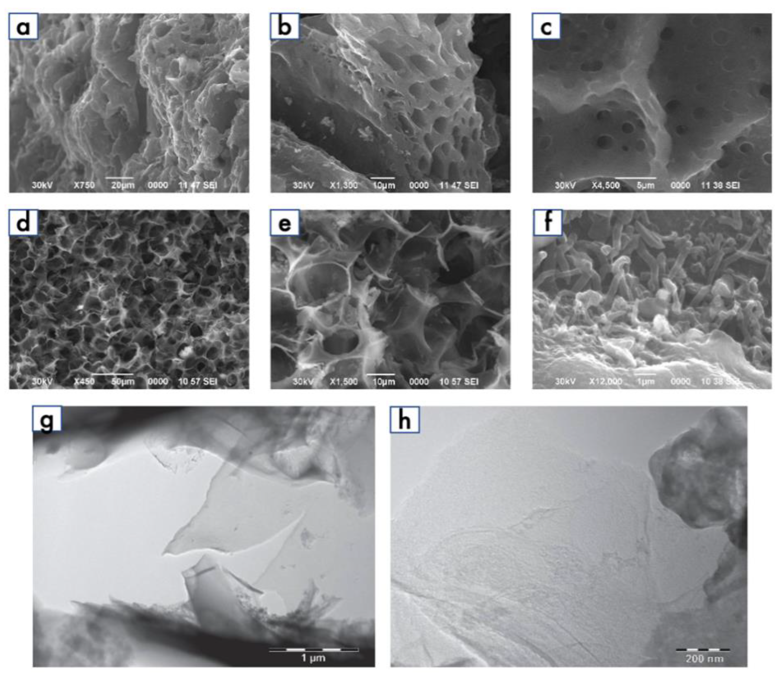
SEM images of the WS-derived carbonaceous products before and after chemical activation are shown in Figure 3. As can be seen, the surface of the WS after carbonization is represented as a rough, dense structure with defects and small indentations (Figure 3a–c). Thermo-chemical activation transformed the WS into a flaky, spongy, and porous GLC structure (Figure 3d–f). This significant surface morphology alteration is explained by the harsh conditions of the thermal transformation/activation when the evacuation of low-volatility compounds results in the formation of new structural arrangements completely different from the initial ones. The TEM analysis of the WS-derived structures (Figure 3g,h) revealed the presence of 2D graphene-like nanosheets of a randomly layered structure in the prepared GLC. Wrinkles and overlapping layers (darker area in the TEM images) are characteristic of biomass-derived graphene and contribute to the porous structure of GLC [28], while the light areas in the TEM images indicate the presence of sparsely layered graphene in the structure [29].
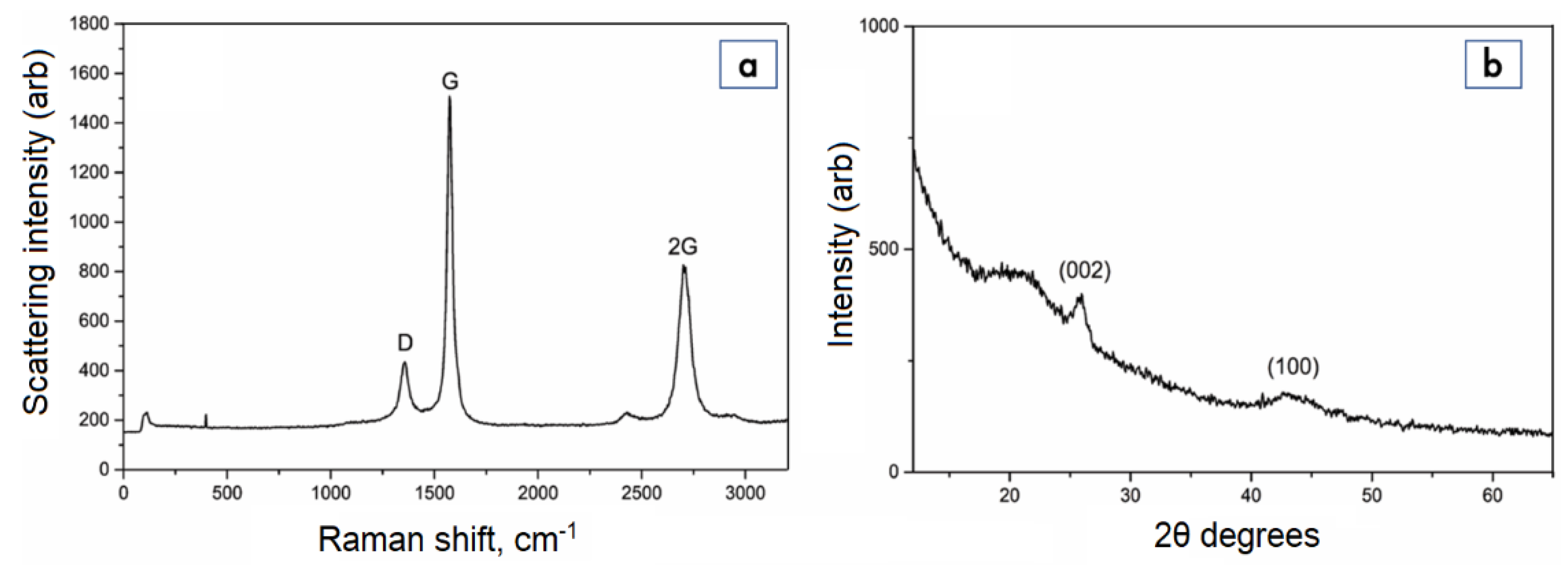
The Raman spectrum of the GLC (Figure 4a) contains both the G-band (1582 cm−1) and the D-band (1357 cm−1). The D-band is related to the edge and structural defects of disordered carbon, while the G-band corresponds to sp2-hybridized carbon atoms, confirming the presence of graphite in the sample. The 2D-band (2717 cm−1) can be used for the calculation of the number of graphene layers in the structure of the GLC [30,31]. According to the ratio of Ig to I2D, the obtained GLC has a sparsely layered (5–7 layers) graphene structure. The graphene-like structure of the GLC was also confirmed through the XRD analysis. The XRD pattern of the GLC sample (Figure 4b) contains a diffraction peak at 25.87 2θ° (002), which corresponds to the formation of a graphene-like structure [32]. A broad peak of low intensity at 43.25 2θ° (100) indicates the absence of a graphitized phase in the sample. The calculated interplanar spacing (d) for the obtained GLC samples is 0.34405 nm, which is close to the theoretical spacing of graphene nanosheets and is higher than that for graphite.
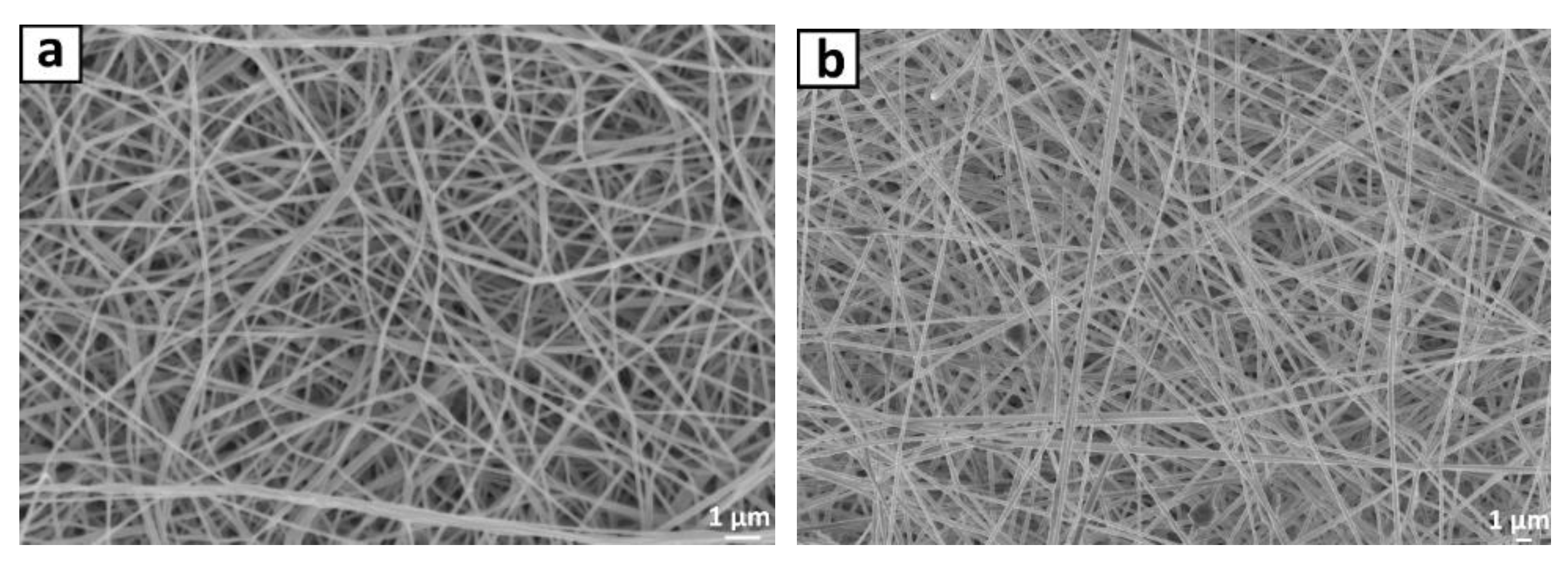
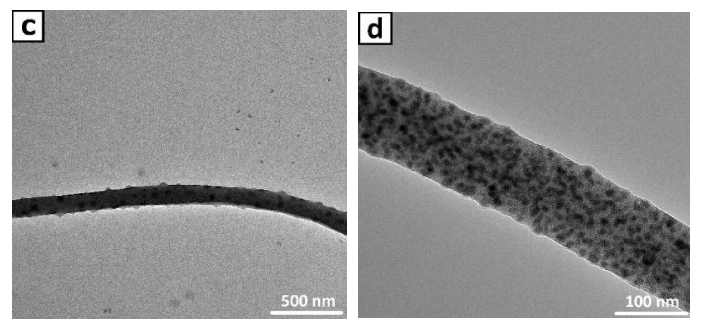
To fabricate the CNFs and CNF/CLC composite, the electrospinning method, followed by the thermal stabilization and calcination of the 1D samples, was used. The structural and morphological characteristics of the CNF and CNF/GLC fibers were investigated by SEM and TEM. The CNF sample in the SEM image (Figure 5a) appears as network of fibers with an average diameter up to 100 nm and a random orientation. In the case of the CNF/GLC composite (Figure 5b), some agglomeration and formation of additional layers along the CNF surface can be observed. These agglomerates are probably caused by the presence of GLC in solution during the electrospinning process. A further investigation of the interaction nature between the CNF and GLC within the composite was performed using TEM. According to the TEM images of the CNF/GLC composite (Figure 5c,d), the nanoplatelets of GLC are homogeneously distributed within the CNF structure. Thus, the successful formation of a homogeneous CNF/GLC composite was confirmed.

3.2. Investigation of the Concrete Unfilled and Filled with CNFs, GLC, and CNF/GLC

3.2.1. Electrical Resistance Tests

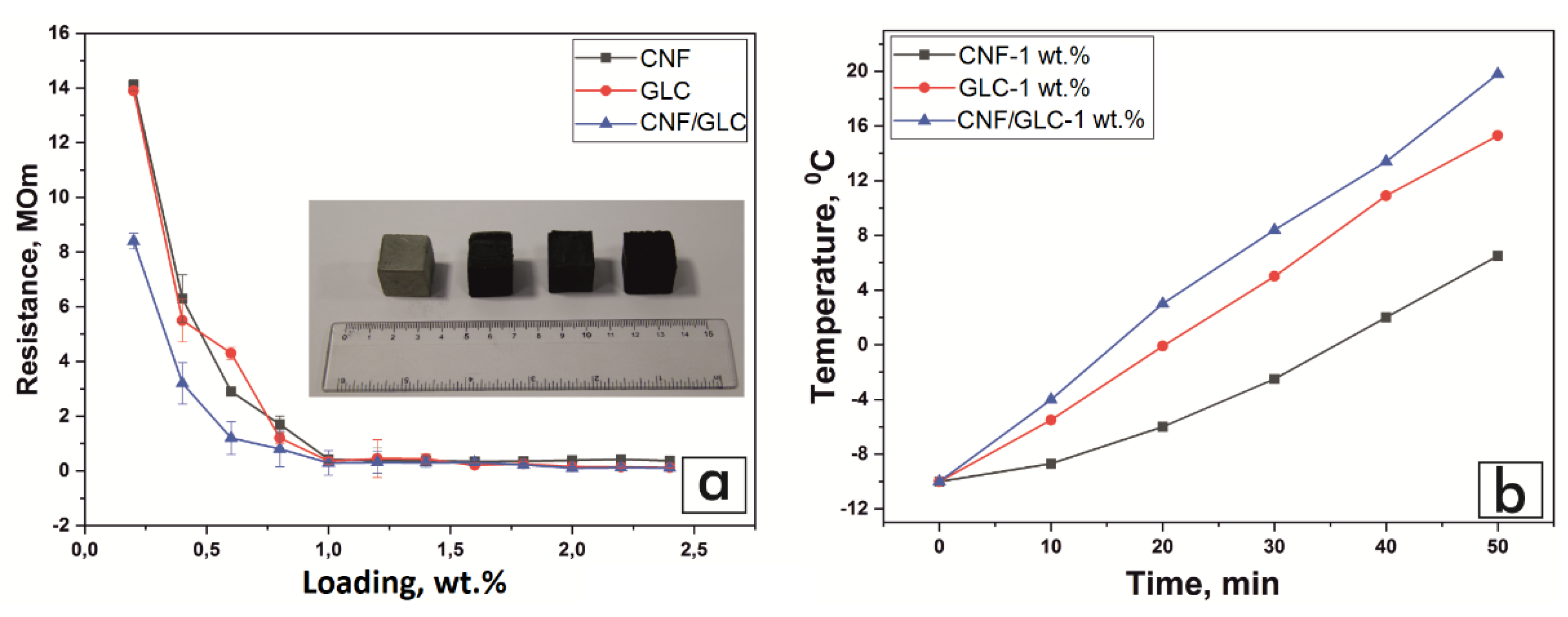
The addition of carbonaceous materials into the concrete mix considerably altered the concrete’s electrical resistance. The introduction of 0.2 wt.% of the CNF/GLC composite into the concrete mix resulted in a sharp decrease in resistance (8.4 ± 0.29 MΩ), which is rather low when compared with the same loading of CNFs (14.1 ± 0.2 MΩ) or GLC (13.9 ± 0.14 MΩ) (Table 2). However, increasing the concentration of the CNF/GLC composite above 1.0 wt.% in the concrete mixture did not lead to an increase in the values of electrical resistance, and when compared to the same values of the CNFs and GLC, the differences in the values of electrical resistance become indiscernible.
The electrical resistance values of the concrete blocks filled with CNF, GLC, or the CNF/GLC composite are presented as a plot function of resistance vs carbonaceous filler loading (Figure 6a). The data analysis confirms that the addition of the CNF/GLC composite at a low amount (0.6 wt.%) significantly affects the electrical resistance of the concrete compared to the control sample (unfilled concrete), for which the resistance value was recorded as 15 ± 0.81 MΩ. The obtained values of electrical resistance for concrete with CNF and GLC content from 0.1 to 2 wt.% are in full agreement with the results of works devoted to the study of various materials, including graphene and CNFs, for electrically conductive concrete preparation [33,34,35]. However, the addition of carbon nanomaterials to the concrete mix at an amount higher than 1 wt.% is not economically viable. According to [36], the addition of 0.5 wt.% CNFs reduces the cost of electrically conductive concrete by 43% compared to the same for nano-sized carbon (at 6 wt.% loading), and by 37% compared to that of recycled metal shavings (at 1.5 wt.% loading). As a result, the addition of the CNF/GLC composite has a more pronounced effect on the electrical properties of the concrete sample.
Obviously, to determine the optimal mass loading of the carbon-based additives, additional long-term studies focused on electrical conductivity (more than 2 years) are required. The results of these long-term investigations would help to determine the dependence of electric resistance on time and evaluate the effects of CNFs, GLC, and the CNF/GLC composite on the corrosion resistance of electrically conductive concrete. As suggested above, the content of carbon materials in the concrete mixture should not exceed 1 wt.%. As shown, the further increase in the amount of added carbon filler to the concrete did not improve its electrical conductivity; instead, it could negatively affect the cost of electrically conductive concrete. Considering the results obtained in the current investigation, further tests of heat performance for the filled concrete specimens were executed for blocks with a 1 wt.% filling.

3.2.2. Heat Performance Tests

Regarding the electric heating-based thermal de-icing approach, the thermal properties of concrete directly depend on its electrical conductivity. Therefore, to investigate the properties of conductive concrete, it is necessary to measure its electrical conductivity and, based on these results, reveal the optimal parameters for the heating of concrete blocks.
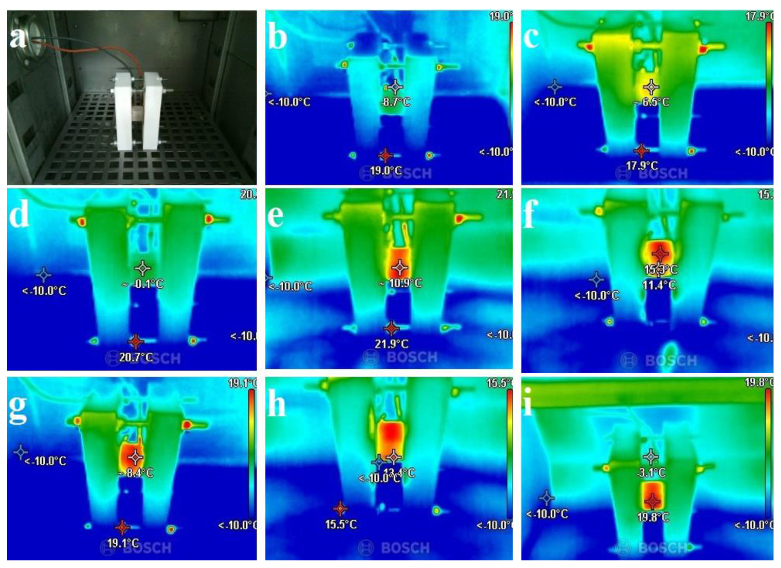
The heating efficiency tests of the concrete blocks with CNFs, GLC, and the CNF/GLC composite (1.0 wt.%) were performed in a climate chamber simulating icing conditions at −10 °C. The increase in the temperature of the concrete blocks was achieved by resistive heating at a voltage of 10 V and was captured by a thermal camera (Figure 7). Each experiment was continued for 50 min with data recorded at 10 min intervals. Data were then plotted as a function of the concrete specimen’s temperature vs. the time of the experiment (Figure 6b). It was found that at over 50 min of experiment time in the climate chamber, the concrete blocks filled with 1 wt.% of CNFs, GLC, and the CNF/GLC composite reached 6.5 °C, 15.3 °C, and 19.8 °C (Figure 6b), respectively, from an initial temperature of −10 °C at the zero moment of the experiment (Figure 6b and Figure 7). Meanwhile, the temperature of the concrete sample without the addition of carbon materials remained unchanged.
It is worth noting that the heating occurred evenly in every filled concrete sample under investigation, which indicates the appropriate selection of the mixing parameters of concrete and carbonaceous fillers. According to the infrared image analysis (Figure 7), the temperature was distributed within the block volumes evenly, while the contact points of the concrete block and copper plates do not create a temperature contrast compared to the other areas, confirming a good affinity between the concrete and copper pads. Since the good surface contact between the copper and the concrete block does not interfere with the passage of the electric current, the contact resistances are minimized in the places where local overheating occurs. During the construction of concrete road transport systems, it may be preferable to use thick copper plates with a conductive gel, which will create uniform contact and distribute the pressure evenly.

3.2.3. Mechanical and Hydrophobic Properties

The influence of the carbon-based additives on the mechanical strength of concrete was investigated by an analysis of the corresponding compressive strengths. It was found that the compressive strength of the concrete specimens increases with an increasing CNF/GLC content. The concrete samples with a content of 1 wt.% and 2 wt.% of the CNF/GLC composite exhibited compression strength values of 23.28 and 33.0 N/mm2 (Figure 8a), respectively, while this value for the unfilled concrete sample was found to be 21.8 N/mm2 (Figure 8a). This can be explained by the uniform distribution of the CNF/GLC within the concrete matrix, which results in a strong interaction of the carbon composite with the cement hydration products, leading to the improved bonding of each part of the concrete matrix. Therefore, when the sample is subjected to external forces, the CNF/GLC in the concrete matrix can inhibit and absorb crack propagation energy, resulting in the increased mechanical strength of the concrete. However, the further increase in the carbon-based composite’s content in the concrete leads to its possible sticking and agglomeration, which complicates its uniform distribution over the concrete matrix during the preparation procedure. These agglomerates have a negative impact on the possibility of the practical application of the prepared concrete mixture, since numerous mechanically unstable zones are formed in the concrete matrix, leading to a decrease in the concrete’s mechanical strength. The wear resistance of concrete is the ability of the concrete surface to resist abrasion. It is known that the use of concrete as a road surface and industrial floors leads to its abrasion, scratching, and slippage due to constant mechanical loads, which result in its surface wear [37,38]. To determine the degree of wear resistance of the concrete, the loss of mass per unit area of the sample and the decrease in the height of the sample subjected to the test were considered. The mechanical tests demonstrated that the concrete sample with 1 and 2 wt.% of the CNF/GLC loadings exhibited abrasion values of 0.93 and 0.98 g/cm2, while for the carbon-free sample this value was established as 0.87 g/cm2. The obtained results confirm that the introduction of carbon composite into a concrete mix leads to a noticeable increase in its wear resistance characteristics.
Hydrophobicity is a vitally important characteristic of coating applications. It has been reported that concrete hydrophobization can be implemented into the manufacture of pavement, as it prevents ion permeability and freeze-thawing leading to the concrete structure’s distortion. In addition, the surface-wetting contact angle in concrete (θ) is an important parameter to define the concrete’s hydrophobicity or hydrophilicity. It is generally accepted that if θ < 90°, the material’s surface is more hydrophilic, and, therefore, water can easily penetrate it; if θ > 90°, the tested surface is more hydrophobic, and water droplets evaporate off of the surface rather than penetrate the capillary. To investigate the influence of the CNF/GLC additive (which has a superior result in the heat performance tests among the filled concrete blocks) on the degree of hydrophobicity of the tested concrete blocks, the surface-wetting angles for the tested specimens were measured and analyzed. Figure 8b–d display the measured results regarding the water contact angles for both the filled and unfilled concrete samples with different CNF/GLC contents. Shown in Figure 8b–d, the wetting angle increased firstly with the CNF/GLC’s addition and then increased further with the further increase in the CNF/GLC content. Although the unfilled concrete is intrinsically hydrophilic (Figure 8b, θ = 24°), it reacts with the filler and then forms a structure with hydrophobic properties. The addition of 1 wt.% of the CNF/GLC composite into the concrete matrix resulted in the increase in the block’s wetting angle to 110.5° (Figure 8c). The further increase in the carbon composite loading in the concrete mixture (2 wt.%) resulted in an increase in the wetting angle up to 138.6° (Figure 8d), indicating the strong hydrophobic properties of the final material. Thus, the addition of the CNF/GLC composite at a loading of 1 wt.% into the concrete mix results in a significant increase in its surface hydrophobicity. In turn, the added ability of the concrete filled with the CNF/GLC composite to conduct an electric current and heat up, along with the hydrophobicity of its surface, have a significant positive effect on its anti-icing behavior and water penetration resistance.
Table 3 summarizes the results of recent works devoted to the fabrication of self-heating concrete. From the Table, it can be seen that the most commonly used additives in concrete mixes are CNFs, inorganic compounds, steel-based fibers, graphite, etc. The de-icing method is commonly divided into electrothermal and microwave-assisted approaches. The detailed analyses of the heating outputs of the modified concrete types are provided in the Table.

4. Conclusions

This research aimed at providing a design approach for de-icing pavement concrete with optimized electrical conductivity and mechanical properties for a critical performance evaluation. The structures of the carbonaceous fillers (CNF and GCL) and their composite (CNF/GCL) as well as a concrete mix were designed, and the efficiency of electrical resistance de-icing was studied. The application value of CNF/GCL in the electrical resistance de-icing of concrete was revealed. From the experimental observations, it has been concluded that:
1. The carbonaceous additive incorporated in the concrete improved its compressive strength, wetting angle, and electrical conductivity compared to the pristine concrete when 0.5 wt.%–1 wt.% was added. The obtained results indicate that the addition of 2.0 wt. % CNF/GLC composite in mortar increases compressive strength by 33.93% compared to unfilled mortar.
2. The addition of 1.0 wt.% carbonaceous additive to the mixture results in an optimum conductive blend for de-icing performance. However, the effect of the CNF/GLC composite is more substantial that the CNF and GLC in terms of performance improvement. The temperature of the modified concrete increases to +19.8 °C at a low voltage (10 V), which indicates the promise of its heat transfer properties for anti-icing applications.
3. When comprehensively considering the hydrophobicity, mechanical strength characteristics, de-icing effect, and economic cost of the concrete filled with CNF/GLC at a 1.0 wt.% rate, it is clear that it achieves the best results for practical applications. In other words, the carbonaceous additive reduces the cost of electrically conductive concrete by 43% compared to the same cost for nano-sized carbon (at 6 wt.% loading), and by 37% compared to that of recycled metal shavings (at 1.5 wt.% loading).
The results show that the CNF/GLC composite has good electrical resistance-heating efficiency. It can be applied in the de-icing of concrete pavement to protect the environment, save natural resources, and utilize agricultural waste. In the future, concrete filled with CNF/GLC would be an attractive candidate for pavement in climatic areas subject to sub-zero temperatures. We propose that future works should be focused on the long-term investigation of the electroconductivity and advanced study of the mechanical properties of concrete composites with CNF/GLC and other types of conductive carbon as additives at various ratios.

Author Contributions

C.D.: Conceptualization, Writing—original draft; F.S., Z.M.: Project administration, Writing—original draft; A.V.K., M.Y.: Methodology; A.T. (Azamat Taurbekov), B.B., A.T. (Aidos Tolynbekov): Investigation, Writing—Review & Editing. All authors have read and agreed to the published version of the manuscript.

Funding

This research is funded by the Science Committee of the Ministry of Science and Higher Education of the Republic of Kazakhstan (Grant No OR11465430).

Data Availability Statement

Data sharing is not applicable to this article.

Conflicts of Interest

The authors declare no conflict of interest.

References

  1. Chen, L.; Yang, Q.; Yang, X.; Liu, Z.; Song, Q. Numerical Investigation of Heat Transfer Performance of Graphene-Doped Anti-/Deicing Component. Therm. Sci. Eng. Prog. 2022, 28, 101098. [Google Scholar] [CrossRef]
  2. Chen, L.; Zhang, Y.; Liu, Z.; Song, Q.; Liu, C. Effect of Graphene Oxide Doping on Anti-/Deicing Performance of Shape Memory Epoxy Resin. Mater. Today Commun. 2022, 30, 103025. [Google Scholar] [CrossRef]
  3. Wang, B.; Yu, P.; Yang, Q.; Jing, Z.; Wang, W.; Li, P.; Tong, X.; Lin, F.; Wang, D.; Lio, G.E.; et al. Upcycling of Biomass Waste into Photothermal Superhydrophobic Coating for Efficient Anti-Icing and Deicing. Mater. Today Phys. 2022, 24, 100683. [Google Scholar] [CrossRef]
  4. Kenzhebayeva, A.; Bakbolat, B.; Sultanov, F.; Daulbayev, C.; Mansurov, Z. A Mini-Review on Recent Developments in Anti-Icing Methods. Polymers 2021, 13, 4149. [Google Scholar] [CrossRef]
  5. Bakr, A.R.; Fu, G.Y.; Hedeen, D. Water Quality Impacts of Bridge Stormwater Runoff from Scupper Drains on Receiving Waters: A Review. Sci. Total Environ. 2020, 726, 138068. [Google Scholar] [CrossRef]
  6. Novotny, E.V.; Murphy, D.; Stefan, H.G. Increase of Urban Lake Salinity by Road Deicing Salt. Sci. Total Environ. 2008, 406, 131–144. [Google Scholar] [CrossRef]
  7. Sanzo, D.; Hecnar, S.J. Effects of Road De-Icing Salt (NaCl) on Larval Wood Frogs (Rana Sylvatica). Environ. Pollut. 2006, 140, 247–256. [Google Scholar] [CrossRef]
  8. Kayama, M.; Quoreshi, A.M.; Kitaoka, S.; Kitahashi, Y.; Sakamoto, Y.; Maruyama, Y.; Kitao, M.; Koike, T. Effects of Deicing Salt on the Vitality and Health of Two Spruce Species, Picea Abies Karst., and Picea Glehnii Masters Planted along Roadsides in Northern Japan. Environ. Pollut. 2003, 124, 127–137. [Google Scholar] [CrossRef]
  9. Rivett, M.O.; Cuthbert, M.O.; Gamble, R.; Connon, L.E.; Pearson, A.; Shepley, M.G.; Davis, J. Highway Deicing Salt Dynamic Runoff to Surface Water and Subsequent Infiltration to Groundwater during Severe UK Winters. Sci. Total Environ. 2016, 565, 324–338. [Google Scholar] [CrossRef] [Green Version]
  10. Alamayreh, M.I.; Alahmer, A.; Younes, M.B.; Bazlamit, S.M. Pre-Cooling Concrete System in Massive Concrete Production: Energy Analysis and Refrigerant Replacement. Energies 2022, 15, 1129. [Google Scholar] [CrossRef]
  11. Li, P.; Li, W.; Sun, Z.; Shen, L.; Sheng, D. Development of Sustainable Concrete Incorporating Seawater: A Critical Review on Cement Hydration, Microstructure and Mechanical Strength. Cem. Concr. Compos. 2021, 121, 104100. [Google Scholar] [CrossRef]
  12. Shishegaran, A.; Daneshpajoh, F.; Taghavizade, H.; Mirvalad, S. Developing Conductive Concrete Containing Wire Rope and Steel Powder Wastes for Route Deicing. Constr. Build. Mater. 2020, 232, 117184. [Google Scholar] [CrossRef]
  13. Gao, J.; Guo, H.; Wang, X.; Wang, P.; Wei, Y.; Wang, Z.; Huang, Y.; Yang, B. Microwave Deicing for Asphalt Mixture Containing Steel Wool Fibers. J. Clean. Prod. 2019, 206, 1110–1122. [Google Scholar] [CrossRef]
  14. Dong, W.; Huang, Y.; Lehane, B.; Aslani, F.; Ma, G. Mechanical and Electrical Properties of Concrete Incorporating an Iron-Particle Contained Nano-Graphite by-Product. Constr. Build. Mater. 2021, 270, 121377. [Google Scholar] [CrossRef]
  15. Chen, L.; Ren, J.; Zhang, Y.; Liu, Z.; Xu, F.; Cheng, J. Microstructure Simulation and Heat Transfer Optimization for Graphene Oxide Doped Anti-/Deicing Composites. Compos. Sci. Technol. 2021, 213, 108901. [Google Scholar] [CrossRef]
  16. Sultanov, F.; Bakbolat, B.; Daulbaev, C.; Urazgalieva, A.; Azizov, Z.; Mansurov, Z.; Tulepov, M.; Pei, S.S. Sorptive Activity and Hydrophobic Behavior of Aerogels Based on Reduced Graphene Oxide and Carbon Nanotubes. J. Eng. Phys. Thermophys. 2017, 90, 826–830. [Google Scholar] [CrossRef]
  17. Lu, S.; Bai, E.; Xu, J.; Chen, J. Research on Electromagnetic Properties and Microwave Deicing Performance of Carbon Fiber Modified Concrete. Constr. Build. Mater. 2021, 286, 122868. [Google Scholar] [CrossRef]
  18. Liu, Z.; Yang, X.; Wang, Y.; Luo, S. Engineering Properties and Microwave Heating Induced Ice-Melting Performance of Asphalt Mixture with Activated Carbon Powder Filler. Constr. Build. Mater. 2019, 197, 50–62. [Google Scholar] [CrossRef]
  19. Atamanov, M.; Amrousse, R.; Jandosov, J.; Hori, K.; Kerimkulova, A.; Chenchik, D.; Kolesnikov, B. Combustion Characteristics of HAN-Based Green Propellant Assisted with Nanoporous Active Carbons. Eurasian Chem.-Technol. J. 2017, 19, 215. [Google Scholar] [CrossRef] [Green Version]
  20. Daulbayev, C.; Sultanov, F.; Korobeinyk, A.V.; Yeleuov, M.; Taurbekov, A.; Bakbolat, B.; Umirzakov, A.; Baimenov, A.; Daulbayev, O. Effect of Graphene Oxide/Hydroxyapatite Nanocomposite on Osteogenic Differentiation and Antimicrobial Activity. Surf. Interfaces 2022, 28, 101683. [Google Scholar] [CrossRef]
  21. Yeleuov, M.; Seidl, C.; Temirgaliyeva, T.; Taurbekov, A.; Prikhodko, N.; Lesbayev, B.; Sultanov, F.; Daulbayev, C.; Kumekov, S. Modified Activated Graphene-Based Carbon Electrodes from Rice Husk for Supercapacitor Applications. Energies 2020, 13, 4943. [Google Scholar] [CrossRef]
  22. Yeleuov, M.; Daulbayev, C.; Taurbekov, A.; Abdisattar, A.; Ebrahim, R.; Kumekov, S.; Prikhodko, N.; Lesbayev, B.; Batyrzhan, K. Synthesis of Graphene-like Porous Carbon from Biomass for Electrochemical Energy Storage Applications. Diam. Relat. Mater. 2021, 119, 108560. [Google Scholar] [CrossRef]
  23. Ming, Y.; Duan, Y.; Zhang, S.; Zhu, Y.; Wang, B. Self-Heating 3D Printed Continuous Carbon Fiber/Epoxy Mesh and Its Application in Wind Turbine Deicing. Polym. Test. 2020, 82, 106309. [Google Scholar] [CrossRef]
  24. Pan, L.; Liu, Z.; kızıltaş, O.; Zhong, L.; Pang, X.; Wang, F.; Zhu, Y.; Ma, W.; Lv, Y. Carbon Fiber/Poly Ether Ether Ketone Composites Modified with Graphene for Electro-Thermal Deicing Applications. Compos. Sci. Technol. 2020, 192, 108117. [Google Scholar] [CrossRef]
  25. Sassani, A.; Arabzadeh, A.; Ceylan, H.; Kim, S.; Sadati, S.M.S.; Gopalakrishnan, K.; Taylor, P.C.; Abdualla, H. Carbon Fiber-Based Electrically Conductive Concrete for Salt-Free Deicing of Pavements. J. Clean. Prod. 2018, 203, 799–809. [Google Scholar] [CrossRef]
  26. Rhee, I.; Lee, J.-S.; Kim, J.H.; Kim, Y.A. Thermal Performance, Freeze-and-Thaw Resistance, and Bond Strength of Cement Mortar Using Rice Husk-Derived Graphene. Constr. Build. Mater. 2017, 146, 350–359. [Google Scholar] [CrossRef]
  27. Daulbayev, C.; Sultanov, F.; Korobeinyk, A.V.; Yeleuov, M.; Azat, S.; Bakbolat, B.; Umirzakov, A.; Mansurov, Z. Bio-Waste-Derived Few-Layered Graphene/SrTiO3/PAN as Efficient Photocatalytic System for Water Splitting. Appl. Surf. Sci. 2021, 549, 149176. [Google Scholar] [CrossRef]
  28. Amiri, M.; Golmohammadi, F. Biomass Derived Hierarchical 3D Graphene Framework for High Performance Energy Storage Devices. J. Electroanal. Chem. 2019, 849, 113388. [Google Scholar] [CrossRef]
  29. Singh, N.; Sharma, M.; Mondal, D.; Maru, D.A.; Rathod, M.R.; Sequeira, R.A.; Chudasama, N.A.; Prasad, K. Seaweed Biomass Derived Bio Solvents for the Large Scale Production of Few Layered Graphene Nanosheets from Graphite. Mater. Sci. Energy Technol. 2021, 4, 100–106. [Google Scholar] [CrossRef]
  30. Prikhod’ko, N.G.; Mansurov, Z.A.; Auelkhankyzy, M.; Lesbaev, B.T.; Nazhipkyzy, M.; Smagulova, G.T. Flame Synthesis of Graphene Layers at Low Pressure. Russ. J. Phys. Chem. B 2015, 9, 743–747. [Google Scholar] [CrossRef]
  31. Ferrari, A.C. Raman Spectroscopy of Graphene and Graphite: Disorder, Electron–Phonon Coupling, Doping and Nonadiabatic Effects. Solid State Commun. 2007, 143, 47–57. [Google Scholar] [CrossRef]
  32. Stobinski, L.; Lesiak, B.; Malolepszy, A.; Mazurkiewicz, M.; Mierzwa, B.; Zemek, J.; Jiricek, P.; Bieloshapka, I. Graphene Oxide and Reduced Graphene Oxide Studied by the XRD, TEM and Electron Spectroscopy Methods. J. Electron. Spectrosc. Relat. Phenom. 2014, 195, 145–154. [Google Scholar] [CrossRef]
  33. Wu, S.; Mo, L.; Shui, Z.; Chen, Z. Investigation of the Conductivity of Asphalt Concrete Containing Conductive Fillers. Carbon 2005, 43, 1358–1363. [Google Scholar] [CrossRef]
  34. AlShareedah, O.; Nassiri, S. Spherical Discrete Element Model for Estimating the Hydraulic Conductivity and Pore Clogging of Pervious Concrete. Constr. Build. Mater. 2021, 305, 124749. [Google Scholar] [CrossRef]
  35. Shen, L.; Yao, X.; Zhu, D.; Alkayem, N.F.; Cao, M.; Ren, Q. A Thermal Cracking Pattern-Based Multiscale Homogenization Method for Effective Thermal Conductivity of Steel Fiber Reinforced Concrete after High Temperature. Int. J. Heat Mass Transf. 2021, 180, 121732. [Google Scholar] [CrossRef]
  36. Dehghanpour, H.; Yilmaz, K.; Ipek, M. Evaluation of Recycled Nano Carbon Black and Waste Erosion Wires in Electrically Conductive Concretes. Constr. Build. Mater. 2019, 221, 109–121. [Google Scholar] [CrossRef]
  37. Zhu, X.; Bai, Y.; Chen, X.; Tian, Z.; Ning, Y. Evaluation and Prediction on Abrasion Resistance of Hydraulic Concrete after Exposure to Different Freeze-Thaw Cycles. Constr. Build. Mater. 2022, 316, 126055. [Google Scholar] [CrossRef]
  38. Saidmurodov, S.S.; Jacobsen, S.; Hendriks, M.A.N.; Shamsutdinova, G. An Evaluation of the Ice Melting during Concrete-Ice Abrasion Experiment. Case Stud. Therm. Eng. 2022, 35, 102088. [Google Scholar] [CrossRef]
  39. Wang, C.; Fu, H.; Ma, W.; Zhang, Z.; Ji, X.; Han, X. Combination Design and Performance Evaluation of Conductive Bonding Layer for Asphalt Pavement Active Deicing. Constr. Build. Mater. 2020, 263, 121037. [Google Scholar] [CrossRef]
  40. Liu, X.; Zhao, Y.; Liu, W.; Yan, D. Microwave Heating and Deicing Efficiency for Asphalt Concrete with SiC–Fe3O4 Microwave Enhanced Functional Layer. J. Clean. Prod. 2022, 332, 130111. [Google Scholar] [CrossRef]
  41. Rao, R.; Fu, J.; Chan, Y.; Tuan, C.Y.; Liu, C. Steel Fiber Confined Graphite Concrete for Pavement Deicing. Compos. Part B Eng. 2018, 155, 187–196. [Google Scholar] [CrossRef]
  42. Zhao, H.; Wu, Z.; Wang, S.; Zheng, J.; Che, G. Concrete Pavement Deicing with Carbon Fiber Heating Wires. Cold Reg. Sci. Technol. 2011, 65, 413–420. [Google Scholar] [CrossRef]
  43. Liu, J.; Xu, J.; Huang, H.; Chen, H. Microwave Deicing Efficiency and Dielectric Property of Road Concrete Modified Using Different Wave Absorbing Material. Cold Reg. Sci. Technol. 2020, 174, 103064. [Google Scholar] [CrossRef]
Figure 1. (a) Scheme of electrospinning setup with a needle and flat horizontal metal collector, and (b) preparation of concrete samples modified with the carbonaceous additive.
Coatings 12 01629 g001
Figure 2. (a) The scheme of the cell setup for measurement of the electrical resistance of cement specimen and (b) optical image of the cell setup with connected digital multimeter.
Coatings 12 01629 g002
Figure 3. Electron microphotographs of WS-derived carbons: (ac) SEM images before thermo-chemical activation; (df) SEM and (g,h) TEM images after thermo-chemical activation.
Coatings 12 01629 g003
Figure 4. (a) Raman spectra and (b) XRD pattern of GLC.
Coatings 12 01629 g004
Figure 5. (a) SEM images of CNF and (b) CNF/GLC composite and (c,d) TEM images of CNF/GLC composite.
Coatings 12 01629 g005aCoatings 12 01629 g005b
Figure 6. Plots of electrical resistance as function of filler loading (a) and concrete specimen temperatures as function of electric current passage time (b) for concrete samples with different carbon additives at 1 wt.% filling rate.
Coatings 12 01629 g006
Figure 7. Digital images of the experimental cell setup within the climatic chamber (a), and thermal images of concrete blocks filled with CNFs (b,c), GLC (df), and CNF/GLC composite (gi).
Coatings 12 01629 g007
Figure 8. (a) Compression strength of CNF/GLC (1 and 2 wt.%) modified concrete blocks compared with pristine concrete block and (b) surface-wetting angles of pristine concrete block and (c) concrete modified with 1 wt.% and (d) 2 wt.% of CNF/GLC.
Coatings 12 01629 g008
Table 1. Specifications of measurement equipment used during the test.
EquipmentManifacturer/ModelSpecifications
Digital multimeter Total (TMT47503)Non-contact voltage detection;
DC Voltage: 600 mV/6 V/60 V/600 V/1000 V ± (0.5% + 3);
Resistance: 600 Ω/6 kΩ/60 kΩ/600 kΩ/6 MΩ ± (0.8% + 3).
Thermal cameraBosch GTC 400 CMeasurement range: 10 °C to + 400 °C;
Measurement accuracy of IR: ±3.0 °C;
Resolution: 0.1 °C;
Focus distance—minimum: 0.3 m.
Table 2. Electrical resistance of concrete after addition of carbon nanomaterials *.
No.CNFGLCCNF/GLC Composite
Content, wt.%Resistance, MΩPower, WContent, wt.%Resistance, MΩPower, WContent, wt.%Resistance, MΩPower, W
10.214.1 ± 0.27.090.213.9 ± 0.147.190.28.4 ± 0.2911.9
20.46.3 ± 0.8715.870.45.5 ± 0.7818.180.43.2 ± 0.7631.25
30.62.9 ± 0.1534.480.64.3 ± 0.2223.260.61.2 ± 0.683.33
40.81.7 ± 0.358.820.81.2 ± 0.2183.330.80.8 ± 0.065125
510.42 ± 0.12238.110.36 ± 0.12277.7810.29 ± 0.045344.83
61.20.38 ± 0.046263.161.20.45 ± 0.069222.221.20.31 ± 0.04322.58
71.40.381 ± 0.17262.471.40.44 ± 0.17227.271.40.3 ± 0.17333.33
81.60.34 ± 0.01294.121.60.21 ± 0.096476.191.60.31 ± 0.1322.58
91.80.35 ± 0.021285.711.80.26 ± 0.078384.621.80.22 ± 0.02454.55
1020.39 ± 0.019256.4120.15 ± 0.042666,6720.1 ± 0.0191000
112.20.42 ± 0.084238.12.20.14 ± 0.035714.292,20.12 ± 0.09833.33
122.40.37 ± 0.014270.272.40.12 ± 0.017833.332.40.11 ± 0.041909.09
CNFGLCCNF/GLC composite
Content, wt.%Resistance, MΩPower, WContent, wt.%Resistance, MΩPower, WContent, wt.%Resistance, MΩPower, W
0.214.1 ± 0.27.090.213.9 ± 0.147.190.28.4 ± 0.2911.9
0.46.3 ± 0.8715.870.45.5 ± 0.7818.180.43.2 ± 0.7631.25
0.62.9 ± 0.1534.480.64.3 ± 0.2223.260.61.2 ± 0.683.33
0.81.7 ± 0.358.820.81.2 ± 0.2183.330.80.8 ± 0.065125
10.42 ± 0.12238.110.36 ± 0.12277.7810.29 ± 0.045344.83
1.20.38 ± 0.046263.161.20.45 ± 0.069222.221.20.31 ± 0.04322.58
1.40.381 ± 0.17262.471.40.44 ± 0.17227.271.40.3 ± 0.17333.33
1.60.34 ± 0.01294.121.60.21 ± 0.096476.191.60.31 ± 0.1322.58
1.80.35 ± 0.021285.711.80.26 ± 0.078384.621.80.22 ± 0.02454.55
20.39 ± 0.019256.4120.15 ± 0.042666.6720.1 ± 0.0191000
2.20.42 ± 0.084238.12.20.14 ± 0.035714.292.20.12 ± 0.09833.33
2.40.37 ± 0.014270.272.40.12 ± 0.017833.332.40.11 ± 0.041909.09
* For the control sample without the addition of carbon nanomaterials, the resistance was 15 ± 0.81 MΩ.
Table 3. Thermal method in concrete de-icing.
Material CompositionApplied De-Icing ApproachCharacteristics of the De-Icing ProcessRef.
Carbon fiber conductive bonding layerElectrothermal At the constant temperature of −5 °C, the surface temperature of the pavement could reach above 0 °C after the conductive bonding layer was electrified for 100 min under 36 V voltage[39]
SiC-Fe3O4Microwave The ice-thawing time of microwave-enhanced functional layer with −15 °C initial temperature was 46 s. It was increased about 1.7 times in contrast to −5 °C.[40]
Carbon fiberMicrowaveThe results show that carbon fiber-modified concrete has the highest heating rate, with a value of 1.680 °C/s, which is 4.46 times higher than that of pristine concrete.[17]
Steel fiber confined graphiteElectrothermalThe average surface power density of the ramps was between 200 W/m2 and 300 W/m2, which is adequate for melting ice in winter environment.[41]
Carbon fiber heating wiresElectrothermalA heating experiment on concrete slabs with carbon fiber heating wires was conducted in a refrigerator at −25 °C. It is shown that with an input power of 1134 W/m2, the temperature on the slab’s surface rises above 0 °C after 2.5 h at an approximate rate of 0.17 °C/min.[42]
Iron black, silicon carbon, and graphiteMicrowaveThe enhancements of the three absorbing materials ranked from high to low are in the following order: graphite, iron black, and silicon carbon.[43]
Carbon fibers/graphene-like porous carbon composite (CNF/GLC) ElectrothermalModified concrete was heated to +19.8 °C at low voltage (10 V).This article
Publisher’s Note: MDPI stays neutral with regard to jurisdictional claims in published maps and institutional affiliations.