Abstract
This work discusses the possibility of decomposing magnesium fluoride by ionized water vapor to form solid magnesium oxide and hydrogen gas in the reaction: MgF2 + H2O → MgO + 2HF. The technology and individual apparatuses of the plasma-chemical installation are described, and the influence of the fractional composition of magnesium fluoride powder on the productivity of the plasma conversion process is considered. To improve the efficiency of the plasma pyrolysis process, a method for making magnesium fluoride briquettes was developed. The completeness of the conversion process of magnesium fluoride to an oxide was evaluated by energy dispersive X-ray spectroscopy in the study of objects in scanning electron microscopy (SEM) and by X-ray diffractometry. It was found that the conversion process of magnesium fluoride to magnesium oxide has a relatively high degree of decomposition of magnesium fluoride fraction ≤75 µm. The use of the proposed processing method makes it possible to obtain pure magnesium oxide as a commercial product and to utilize fluorine-containing industrial waste.
1. Introduction
The production cycle of most industrial enterprises is an open system, characterized by the formation of a large amount of solid, liquid, and gaseous waste. At present, Ulba Metallurgical Plant JSC (UMP JSC) of the Kazakhstan is one of the few plants in the world that uses the magnesium-thermal reduction technology of beryllium fluoride to produce metallic beryllium. According to the technological scheme, beryllium is produced by reducing beryllium fluoride with magnesium in the chemical reaction: BeF2 + Mg → MgF2 + Be [1]. When carrying out the reaction with stoichiometric ratio of components the separation of pyrolysis products is low, and on this basis, large amounts of BeF2 are added to the charge. If magnesium is added to the mixture in the amount of only 75% stoichiometric, good results of pyrolysis products from the separation reaction can be achieved. A large excess of BeF2 leads to the rapid grinding of slag. Magnesium fluoride is present in the slag in the form of large needle crystals, each of which is enclosed in a film of BeF2. In the process of wet milling, the film of BeF2 dissolves, the slag cracks, and the metallic beryllium particles are released. Excessive BeF2 makes the slag more fusible and flowable, dissolves the BeO, reduces the equilibrium amount of magnesium in the reaction mixture and partially bonds MgF2. To remove impurities (slag, magnesium and intermetallic compounds) from the magnesium-thermal beryllium, a vacuum melting process is carried out in induction furnaces at a pressure of 133–267 Pa and a temperature of 1500–550 °C. Free Mg and BeF2 evaporate, and non-volatile impurities MgF2, BeO, Be2C, etc., float to the melt surface or settle at the crucible bottom as slag. After this operation, the magnesium fluoride (MgF2) is filtered off, washed, and sent to the waste dump. It is known that MgF2, which has a rutile structure, is characterized by high transparency in an extremely wide range of photon energies, from vacuum ultraviolet to infrared, and therefore has many applications in various optical devices (e.g., lenses, filters, windows, laser elements, and is also a potential material for radiation measurements, especially for dosimetry applications [2,3]). However, due to the growing demand for beryllium production, the annual generation of magnesium fluoride as industrial waste is expected. Due to this, the development of a magnesium-fluoride-processing technology which obtains magnesium oxide as a commercial product is an urgent task. At present, intensive work is being carried out to find and develop new technological solutions in metallurgy.
One of the ways to solve the problem of waste processing is the use of the plasma-chemical method, i.e., the chemical method of producing highly dispersed powders of nitrides, carbides, borides, and oxides, which occurs in a reaction in low-temperature plasma far from equilibrium at a high rate of nucleation of new phase and their low growth rate. UMP JSC has developed a pilot plasma-chemical technology for obtaining magnesium oxides from magnesium fluoride waste [4,5]. Plasma pyrolysis is a modern technology that offers a promising future for the efficient treatment of solid waste [6,7,8,9]. The advantage and peculiarity of this plasmachemical method is the high energy content of heat flow (the temperature of plasma coolants reaches ~104 K, their enthalpy values are 100–200 kcal/mol), which provides a large specific capacity of the equipment [10,11]. Because of this, the use of plasma chemistry is appropriate for the implementation of endothermic processes, such as obtaining oxides from salt solutions, which require a high energy input. Such a process does not require the use of chemical precipitator reagents, so the volume of discharged solutions is reduced [12].
Plasma metallurgy, due primarily to the technological effect and economic performance of these processes, is designed to produce metallic materials with certain physical properties. Plasma metallurgy opens up new metallurgical possibilities associated with a significant concentration of thermal energy and higher rates of chemical reactions. From the point of view of thermodynamics, high temperatures indicate an increasing role of entropic factors. The impact of high temperatures on chemical compounds can be used for their disaggregation and decomposition. High rates of chemical reactions involving low-temperature plasma can be used to restore metal compounds in continuous processes. The high reactivity of the active gas atmosphere and the concentration of thermal energy of plasmatrons are used to produce nitrides, borides, and oxides of refractory metals. A known method of processing fluorine-containing beryllium concentrates involves subjecting them to pyrohydrolysis in a stream of water-steam plasma, including steam-plasma splitting of phenacite and bertrandite minerals, forming oxides and silicic fluoric acid [13,14]. The industrial application of ore stripping processes in plasma has been put into practice in various countries around the globe. For example, the South African Atomic Energy Corporation has developed a plasma process by which zircon, ZrSiO2, may be subjected to phase dissociation at temperatures above 1700 °C [15]. The product of zircon dissociation is zirconium (IV) oxide and silicon (IV) oxide, a reaction which occurs when zircon is heated in a plasma flow, as a highly dispersed powder. Silicon (IV) oxide is easily leached from it, and the purity of zirconium (IV) oxide is 99.9 wt.%. For the industrial implementation of plasma technologies, it is necessary to investigate the basic parameters of the plasma processes of reducing gases and metal oxides’ treatment with them to assess the economic efficiency of plasma-metallurgical processes; this would be for the purpose of solving the issues of their hardware design and increasing knowledge of the plasmatron for their use in continuous metallurgical processes. The purpose of this work is to study the process of the plasma-chemical decomposition of magnesium fluoride by ionized water, in the form of steam, according to the reaction: MgF2 + H2O → MgO + 2HF, depending on the amount of the initial powder.
2. Materials and Methods
The essence of the experiment is that the waste magnesium fluoride, which is formed as a result of magnesothermal reduction of beryllium fluoride, is recycled using the technology of plasma-chemical decomposition of magnesium fluoride with ionized water steam, using an installation based on a plasma-chemical reactor. Magnesium fluoride with a main substance content of 99% is fed into a reaction chamber in plasmatron with a temperature of 2800–2850 K, and a steam–gas mixture formed as a result of pyrohydrolysis is directed to the device for forced cooling and catching solid magnesium oxide particles. Dust–gas products then arrive to be further filtered by the device for condensed gaseous products. The present work considers the possibility of decomposition of magnesium fluoride by ionized water steam with the formation of solid magnesium oxide and gaseous hydrogen by reaction: MgF2 + H2O → MgO + 2HF.
To realize the process of magnesium fluoride processing by plasma-chemical decomposition, a plasmatron is used as a heating source. Usually, plasmatrons use inert gases as the operating gas, which are easily ionized and protect the cathode of the plasmatron from oxidation (it is made of tungsten). At the same time, there are designs of plasmatrons where water steam is used as the operating gas. For this work, this design of the plasmatron is ideal, since it is required to use water in the decomposition reaction of magnesium fluoride. For the plasma-chemical process, a plasmatron was designed and developed (Figure 1).
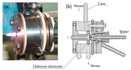
Figure 1.
Plasmatron: (a) appearance; (b) assembly drawing.
Figure 2 shows the scheme of the plasma-chemical reactor. The reactor is a thermally insulated graphite felt tube (1) placed in the steel case (2). Between the case (2) and the plasmatron is a graphite insert with a nozzle, closely adjacent to the plasmatron. There is a hole in the graphite insert, where powdered fluorite is fed by a sleeve (3). The plasma cord comes out of the nozzle of the plasmatron and captures the fluorite powder, heating and steaming it. The plasma mixture flies through the red-hot graphite sleeve and leaves the plasma reactor, outside of which there will be a device to separate the magnesium oxide from the hydrogen fluoride steam.
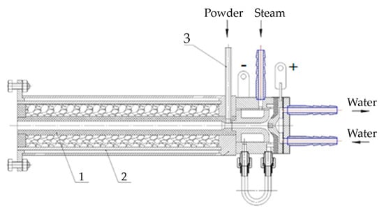
Figure 2.
Scheme of plasma-chemical reactor: 1—graphite tube; 2—case; 3—sleeve for powder feeding.
A low-pressure (up to 2 kgf/cm2) steam generator was used to supply the plasmatron with water steam at a temperature of up to 130 °C. Using a steam generator allows the easy regulation of the supply of water steam to the plasmatron using a valve. For the dosing of powdered fluorite into the reaction chamber, a special plate-type dosing device is used, which allows it to precisely control the rate of material feeding. General scheme of the plasma-chemical installation is shown in Figure 3.
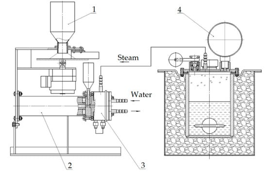
Figure 3.
Scheme of plasma-chemical installation: 1—plate-type dispenser; 2—plasma-chemical reactor; 3—plasmatron; 4—steam generator with electric contact gauge.
The completeness of the conversion process of magnesium fluoride to oxide is evaluated by the results of X-ray diffraction phase and particle size analyses. The size characteristics of MgF2 and MgO powders were investigated on an Analysette-22 Nanotech laser diffraction analyzer (Fritsch, Idar-Oberstein, Germany); microphotographs of the powders were obtained using a TESCAN MIRA scanning electron microscope (TESCAN, Brno, Czech Republic). X-ray diffraction phase analysis was performed on an X’PertPro (Philips, Amsterdam, the Netherlands) with CuKα radiation at 40 kV and 30 mA. Thermal analyses were performed on a TGA/DSC2 thermogravimetric analyzer (METTLER TOLEDO, Greinfensee, Switzerland) [16]. The sensitivity of the scales was 0.1 µg over the entire measurement range. The mass of the sample was 88,366 mg. The sensitivity of the scales was 0.1 µg. Experiments were performed in the temperature range 20–1300 °C, in atmospheric air current, at a heating rate of 10 °/min in corundum and platinum crucibles. The heat of phase transitions was calculated as the area under the measured peak according to ISO 11357-1 DIN 51007.
Magnesium fluoride from the magnesium-thermal reduction of beryllium was used as a starting powder (Figure 4). Physical properties of magnesium fluoride are shown in Table 1.
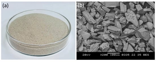
Figure 4.
(a) appearance and (b) micrograph of magnesium fluoride powder.

Table 1.
Physical properties of MgF2.
3. Results and Discussion
Steam-water plasma, on the temperature, consists of hydrogen, oxygen and their derivatives. This composition of the steam-water plasma determines its redox character and high ecological safety when carrying out different plasma-chemical processes. The highest values of enthalpies in steam-water plasma are determined by strong intra-atomic bonds due to the small size of hydrogen atoms. For example, the enthalpy of this composition of steam-water plasma at 5000 K is 7.25 more than the enthalpy of air at 5000 K. This affects the high rate of thermal reaction with other technological components engaged in the plasma-chemical process, compared to other plasmas. Plasma-chemical reactions in steam plasma proceed with the highest thermal efficiency, due to the elimination of ballast components, such as nitrogen in air plasma. A significant number of high-temperature metallurgical processes are realized due to the operating temperature of the low-temperature plasma stream, which is 5000 °C and higher. Thermogravimetric analysis of magnesium fluoride was carried out to assess the possibility of implementation (Figure 5).
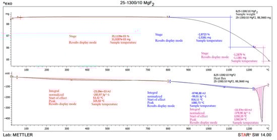
Figure 5.
The result of thermogravimetric analysis of magnesium fluoride MgF2.
The thermogravimetric analysis of magnesium fluoride showed that the sample is practically stable when heated up to 1080.73 °C. A small 0.035% increment can be attributed to magnesium fluoride oxidation when heated to 325.5 °C. The combustion process of the sample begins at 1080.73 °C and ends at 1260.54 °C. The endothermic effect at 1260.54 °C and mass loss relate to the magnesium fluoride melting. It is known that magnesium fluoride has substantially higher reactivity than BeF2 CaF2, although the conditional temperature of the beginning of pyrohydrolysis of MgF2 is about 1600 °C. Powdered MgF2 starts sintering before pyrohydrolysis starts, and as a result the boundary of phase transformation of MgF2 into MgO depends on its being parallel to external surface of initial fluoride layer, and reaction rate depends on sample shape.
In the method of recycling of solid waste particles suspended in plasma flow, the important parameter is the particle size of the initial substance (MgF2), which is fed into the plasma in powder form. In the plasma flow, the following processes take place: heating of raw material particles to high temperature, their melting, evaporation, chemical reactions, formation of product particles, and cooling. The main disadvantage of the plasma-chemical method is the heterogeneous interaction of solid and liquid particles of the feedstock with plasma. The process of plasma-chemical decomposition of magnesium fluoride powder, with fractions ≤300, ≤100, ≤75 μm, was investigated experimentally. The completeness of the conversion process of magnesium fluoride to an oxide was evaluated by energy dispersive X-ray spectroscopy in an SEM study of the objects. Figure 6, Figure 7 and Figure 8 show the granulometric composition of MgF2 powder and SEM images with EDS results (Map Sum Spectrum is shown) after plasma-chemical treatment. The best qualitative characteristics have magnesium oxide obtained by the fraction ≤75 μm, as this achieves melting of the material particles.
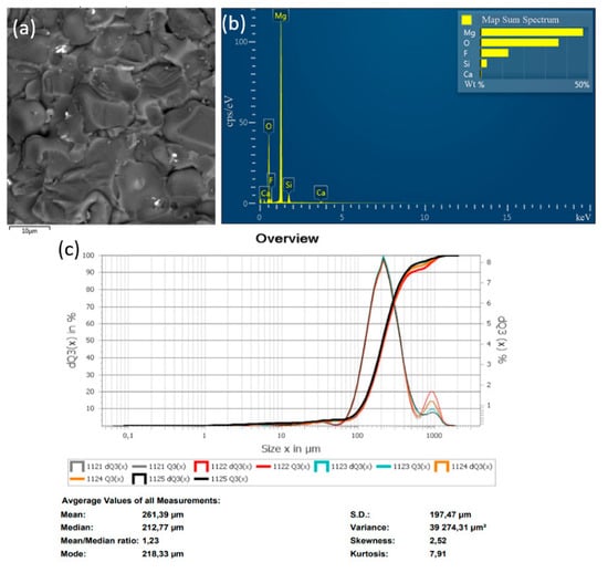
Figure 6.
Results of the decomposition experiment of magnesium fluoride powder with a particle size of ≤300 μm: (a) SEM image; (b) EDS analysis result; (c) particle size distribution of MgF2 powder.
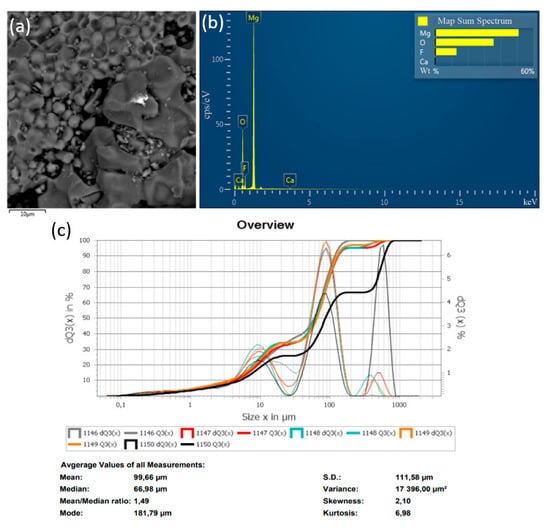
Figure 7.
Results of the decomposition experiment of magnesium fluoride powder with a particle size of ≤100 μm: (a) SEM image; (b) EDS analysis results; (c) particle size distribution of MgF2 powder.

Figure 8.
Results of the decomposition experiment of magnesium fluoride powder with a particle size of ≤75 µm: (a) SEM image; (b) EDS analysis result; (c) particle size distribution of MgF2 powder.
Figure 9 shows diffractograms of powders obtained by the plasma-chemical decomposition of magnesium fluoride at different fractions, ≤300, ≤100, ≤75 μm. The relative intensity of diffraction peaks is related to the quantitative phase content in the studied sample. Based on the results of X-ray diffraction phase analysis, the conversion process of magnesium fluoride into magnesium oxide has a relatively high degree of decomposition of magnesium fluoride fraction ≤75 μm. This conclusion is confirmed by the results of EDS analysis.
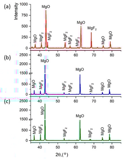
Figure 9.
Powder diffractogram after plasma-chemical decomposition of magnesium fluoride at different fractions: (a) ≤300 μm; (b) ≤100 μm; (c) ≤75 μm.
To improve the efficiency of the plasma pyrolysis process, a method for making briquettes from MgF2 was developed. For steam plasma processing, a technology for forming briquettes from magnesium fluoride powder using an aqueous solution of polyvinyl alcohol as a binder was developed. It is experimentally confirmed that the briquetting of magnesium fluoride powder can increase the productivity of the plasma conversion process. The main requirement for the method of briquetting is the use of a binder that does not introduce foreign impurities into the final product. The following types of binders were assessed: paraffin, ammonium stearate, and polyvinyl alcohol (PVA). It was found that when using paraffin, the reaction product is contaminated with residual carbon, but ammonium stearate and PVA do not introduce contaminating impurities. Based on the cost ratios of the binder elements, PVA was recommended for making briquettes from MgF2. When the particle size distribution of the initial MgF2 powder was studied, it was found that the particle size ≥75 μm contributes to a dense packing of particles in the process of making briquettes (Figure 10). The result of the investigation of the size characteristics of the MgF2 powder is shown in Figure 10b; each point of the integral curve Q3(x) shows how many percent of particles are smaller or equal to the given size, and each point of the histogram dQ3(x) shows the number of particles, in percent, with the given size.
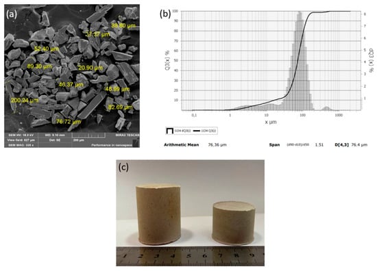
Figure 10.
Powder of magnesium fluoride MgF2: (a) SEM image; (b) granulometric composition; (c) MgF2 briquettes.
Experiments on melting briquettes made of magnesium fluoride were carried out. The briquette was brought manually to the plasmatron for melting with the help of tongs. The gaseous mixture of water steam and hydrogen fluoride was captured with water to produce a hydrogen fluoride solution (hydrofluoric acid).
Fragments of images of plasma treatment product (MgO) obtained by scanning electron microscopy are shown in Figure 11. The obtained magnesium oxide particles have a melted shape, while small particles tend to form agglomerates. According to Figure 11b, magnesium oxide particles have a clad surface. Granulometric analysis of the obtained magnesium oxide powder is shown in Figure 12. According to the data shown in Figure 12, the range of particle sizes is about 0.1 to 1050 µm, with the predominance of particles possessing a diameter of 600–800 µm due to the partial formation of agglomerates.
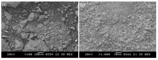
Figure 11.
SEM image: (a) of the product of plasma-chemical treatment; (b) of a fragment of the image of the surface of the agglomerated MgO particle.
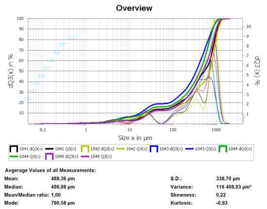
Figure 12.
Granulometric composition of magnesium oxide powder.
Figure 13 shows diffractograms of briquettes obtained from magnesium fluoride before and after plasma-chemical decomposition of magnesium fluoride. The results of X-ray diffraction phase analysis showed that magnesium fluoride briquetting contributes to obtaining pure magnesium oxide. Table 2 shows the values according to GOST 4526 “Magnesium oxide. Technical requirements”.
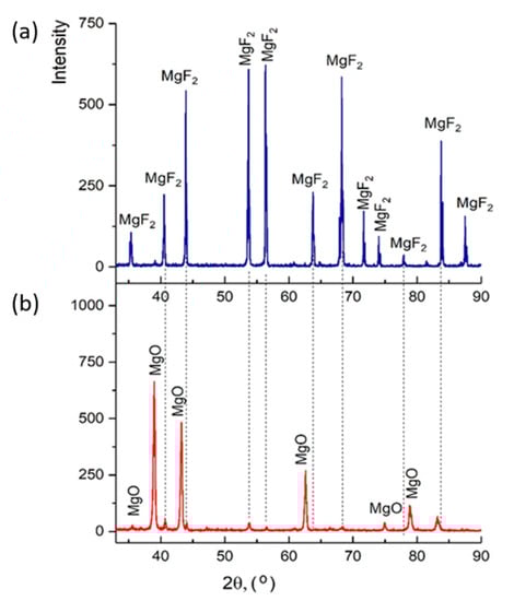
Figure 13.
Diffractograms: (a) magnesium fluoride; (b) magnesium oxide (final product).
Table 2.
Technical requirements for magnesium oxide according to GOST 4526.
Based on the results of the research, it can be concluded that the magnesium oxide powder obtained by plasma conversion meets the requirements for magnesium oxide according to GOST 4526-75. It is planned to use magnesium oxide as a refractory in beryllium production. In the process of magnesium fluoride steam-plasma conversion, the most important product of the reaction was hydrogen fluoride. Capturing of gaseous hydrogen fluoride with water resulted in a weak solution of hydrofluoric acid (less than 1%). Due to the lack of technical possibilities, it was not possible to obtain more concentrated hydrofluoric acid during the research.
Therefore, the plasma-chemical method of industrial waste recycling can be applied instead of the existing method of magnesium fluoride processing by hydrometallurgical method, in which magnesium fluoride is dissolved in acids and alkalis with the subsequent precipitation of magnesium oxide and withdrawal of fluoride-containing products by concentrating or evaporating solutions. The technology of magnesium fluoride steam-plasma conversion has the following advantages:
- The steam-plasma gasification process is not sensitive to the humidity of the treated materials;
- Steam plasma is not explosive;
- No chemical reagent solutions are required for the leaching, sedimentation, and washing of sediments, thus reducing the formation of liquid waste; the actions to minimize environmental damage are thus reduced.
4. Conclusions
The main results of the work are:
- Thermogravimetric analysis of magnesium fluoride showed that the melting process of magnesium fluoride occurs at a temperature range from 1080.73 °C to 1260.54 °C;
- The results of X-ray diffractometry testify to high efficiency of the process of plasma-chemical conversion of magnesium fluoride to magnesium oxide and the exclusion of intermediate magnesium oxyfluorides formation;
- It is shown that the method of briquetting of powder with a fraction of ≤75 µm can be used to improve the homogeneity of the plasma-chemical process of MgF2 decomposition. To briquette magnesium fluoride powder, an aqueous solution of polyvinyl alcohol was used as a binder;
- It is shown that by using the plasma-chemical method of magnesium fluoride processing, it is possible to obtain magnesium oxide with main substance content of 99 % and hydrogen fluoride. Magnesium oxide has characteristics which meet the requirements of GOST 4526 “Magnesium oxide”. Technical requirements of “Pure” grade, suitable for use in the electrical industry, as well as for the manufacture of refractory material used in the metallurgical industry.
Author Contributions
Z.S. and M.K. designed the experiments; K.S. and M.P. performed the experiments; B.R., M.Y. and Z.S. analyzed the data; Z.S. and Y.K. wrote, reviewed and edited the paper. All authors have read and agreed to the published version of the manuscript.
Funding
This research was funded by the Science Committee of the Ministry of Education and Science of the Republic of Kazakhstan. Grant AP08857800.
Institutional Review Board Statement
Not applicable.
Informed Consent Statement
Not applicable.
Data Availability Statement
Not applicable.
Conflicts of Interest
The authors declare that there is no conflict of interest regarding the publication of this.
References
- Naboychenko, S.S.; Murashova, I.B.; Neikov, O.D. Production of Rare Metal Powders, 2nd ed.; Elsevier: Amsterdam, The Netherlands, 2009; pp. 485–537. [Google Scholar]
- Lisitsyna, L.A.; Popov, A.I.; Karipbayev, Z.T.; Mussakhanov, D.A.; Feldbach, E. Luminescence of MgF2-WO3 ceramics synthesized in the flux of 1.5 MeV electron beam. Opt. Mater. 2022, 133, 112999. [Google Scholar] [CrossRef]
- Popov, A.I.; Elsts, E.; Kotomin, E.A.; Moskina, A.; Karipbayev, Z.T.; Makarenko, I.; Pazylbek, S.; Kuzovkov, V.K. Thermal annealing of radiation defects in MgF2 single crystals induced by neutrons at low temperatures. Nucl. Instrum. Methods Phys. Res. Sect. B Beam Interact. Mater. At. 2020, 480, 16–21. [Google Scholar] [CrossRef]
- Kylyshkanov, M.K.; Shestakov, K.A.; Sagdoldina, Z.B.; Rakhadilov, B.K.; Kengesbekov, A.B. Processing of industrial waste by plasma-chemical method. Bull. Univ. Karaganda 2021, 3, 45–51. [Google Scholar] [CrossRef]
- Kylyshkanov, M.K.; Shestakov, K.A.; Sagdoldina, Z.B.; Abdulina, S.A.; Rakhadilov, B.K. Assessment of thermodynamic parameters of the plasma chemical process for magnesium oxide production. Eurasian J. Phys. Funct. Mater. 2022, 6, 151–158. [Google Scholar] [CrossRef]
- Bhatt, K.P.; Patel, S.; Upadhyay, D.S.; Patel, R.N. A Critical Review on Solid Waste Treatment using Plasma Pyrolysis Technology. Chem. Eng. Process. Process Intensif. 2022, 177, 108989. [Google Scholar] [CrossRef]
- Messerle, V.E.; Mossé, A.L.; Paskalov, G.; Sitdikov, Z.Z.; Ustimenko, A.B. Plasma Chemical Conversion of Spent Lubricating Materials. J. Eng. Phys. Thermophys. 2021, 94, 1344–1356. [Google Scholar] [CrossRef]
- Messerle, V.E.; Mossé, A.L.; Ustimenko, A.B.; Slavinskaya, N.A.; Sitdikov, Z.Z. Recycling of Organic Waste in a Plasma Reactor. J. Eng. Phys. Thermophys. 2020, 93, 987–997. [Google Scholar] [CrossRef]
- Li, J.; Liu, K.; Yan, S.; Li, Y.; Han, D. Application of thermal plasma technology for the treatment of solid wastes in China: An overview. Waste Manag. 2016, 201658, 260–269. [Google Scholar] [CrossRef] [PubMed]
- Rakhadilov, B.K.; Kenesbekov, A.B.; Kowalevski, P.; Ocheredko, Y.A.; Sagdoldina, Z.B. Development of air-plasma technology for hardening cutting tools by applying wear-resistant coatings. News Natl. Acad. Sci. Repub. Kazakhstan Ser. Geol. Tech. Sci. 2020, 3, 54–62. [Google Scholar] [CrossRef]
- Chu, P.K.; Lu, X. Low Temperature Plasma Technology: Methods and Applications, 2nd ed.; Taylor and Francis: London, UK, 2013; 493p. [Google Scholar]
- Sikarwar, V.S.; Hrabovský, M.; Van Oost, G.; Pohořelý, M.; Jeremiáš, M. Progress in waste utilization via thermal plasma. Prog. Energy Combust. Sci. 2020, 81, 100873. [Google Scholar] [CrossRef]
- Arinov, B.Z.; Kening, V.K. Studies on integrated processing of beryllium-containing concentrates using the plasma chemical method. In Proceedings of the International Scientific and Technical Conference “Innovative Technologies and Projects in the Mining and Metallurgical Complex”, Almaty, Kazakhstan, 18–19 March 2014. (In Russian). [Google Scholar]
- Kazakhstan Patent Database. Available online: https://kzpatents.com/4-ip31040-sposob-pererabotki-ftorsoderzhashhih-berillievyh-koncentratov.html (accessed on 17 September 2007). (In Russian).
- Du Plessis, W.; Pienaar, A.D.; Postma, C.J.; Crouse, P.L. Effect of the value of x in NH4F·xHF on the digestion of plasma-dissociated zircon. Int. J. Miner. Process. 2016, 147, 43–47. [Google Scholar] [CrossRef][Green Version]
- Warne, S.S.; Gallagher, P.K. Thermomagnetometry. Thermochim. Acta 1987, 110, 269–279. [Google Scholar] [CrossRef]


Publisher’s Note: MDPI stays neutral with regard to jurisdictional claims in published maps and institutional affiliations. |
© 2022 by the authors. Licensee MDPI, Basel, Switzerland. This article is an open access article distributed under the terms and conditions of the Creative Commons Attribution (CC BY) license (https://creativecommons.org/licenses/by/4.0/).