Article

Secondary Structures on the Friction Surface of Diamond-like Coating

1
Joint Stock Company Railway Research Institute, Moscow State Technological University “Stankin” (MSTU “STANKIN”), 127994 Moscow, Russia
2
Department of Mechanical Engineering, McMaster Manufacturing Research Institute (MMRI), McMaster University, Hamilton, ON L8S 4L8, Canada
3
Ishlinsky Institute for Problems in Mechanics RAS, 119526 Moscow, Russia
4
Coating and Heat Treatment Laboratory, Moscow State Technological University “Stankin” (MSTU “STANKIN”), 127994 Moscow, Russia
5
Department of Engineering, Universidad Loyola Andalucia, Av de las Universidades s/n, 41704 Dos Hermanas, Spain
6
Nano4Energy SL, José Gutiérrez Abascal 2, 28006 Madrid, Spain
*
Author to whom correspondence should be addressed.
Coatings 2022, 12(11), 1685; https://doi.org/10.3390/coatings12111685
Submission received: 7 October 2022 / Revised: 28 October 2022 / Accepted: 3 November 2022 / Published: 5 November 2022

Abstract

:
Peculiarities of the formation of secondary structures on the surface of a diamond-like coating are studied on the example of a friction contact between a steel ball and a diamond-like coating. The friction surface was examined in various areas; the zone of wear products (the boundary of the friction track) and the original surface outside the friction area. It is shown that secondary structures with a high content of iron, nickel, manganese, chromium, and oxygen are characteristic of areas with the highest wear resistance. Such secondary structures are formed because of the intense interaction of the diamond-like coating with the steel of the ball during dry friction.

1. Introduction

One of the common ways to improve the reliability and service life of various components and mechanisms is to modify their surface by applying functional coatings [1]. Among the various types of such coatings, diamond-like carbon (DLC) has been of particular interest to researchers since 1971, when Aisenberg and Chabot [2] developed a method of thin carbon film deposition by ion-beam. These films exhibited properties close to those of diamond and were called diamond-like. Such coatings are dielectrics and have high thermal conductivity, good optical transparency, chemical inertness, and biocompatibility; therefore, they are used in various fields of optics, mechanics, electronics, and biomedicine [3]. They also have a low coefficient of friction, high hardness, and wear resistance, making them suitable for tribological applications [4,5,6,7]. DLC structure determines the coating’s properties.
As is known, carbon forms a wide variety of crystalline and disordered structures since it can exist in three hybrid forms: sp1 (carbon chains), sp2 (graphite-like), and sp3 (diamond-like). DLC is a metastable form of amorphous carbon with a significant proportion of sp3-type carbon bonds. The cluster model gives the simplest idea of their structure. It is assumed that sp2 structures are located in clusters of a certain size embedded in a matrix with sp3 bonds [8,9]. In addition, the structure may contain hydrogen, which has a significant effect on the mechanical properties [10]. In [11], DLCs were classified into several types depending on the proportion of sp3 bonds (they can reach almost 90%) and the hydrogen content (up to 50%–60%). Among them, the hydrogenated form (aC:H) is more ordered in contrast to the hydrogen-free form of amorphous carbon (ta-C); the existence of the last one was considered unlikely [12,13]. Thus, the ratio of sp3 and sp2 bonds of carbon determines the properties of DLC, which depend on the deposition method. The main methods for coating deposition are chemical and physical vapor deposition (CVD and PVD) methods with direct current (DC) or radio frequency (RF) sputtering. Cathode-arc sputtering, pulsed laser sputtering, plasma-enhanced chemical vapor deposition (PECVD), etc., are often used [8,14,15]. Various methods of coating formation make it possible to obtain DLC with a wide range of properties. It is known that the difference in the thermal and elastic properties of the coating and the substrate can lead to a low level of adhesion at the interface, which negatively affects reliability. Therefore, to improve the adhesion of the coating to the substrate, it is common practice to apply an intermediate layer before coating [16,17,18].
Additional doping of DLC [19,20,21,22,23,24,25] is widely used to improve the mechanical and tribological properties (for example, by silicon). An increase in the silicon concentration in the coating leads to less wear resistance [26]; therefore, in this study, the silicon content in the DLC is 0.5–1 wt.%. Silicon doping of films of hydrogenated diamond-like carbon reduces the residual internal stress, slightly affecting mechanical hardness [27].
Friction induces graphitization of DLC surface layers [28,29,30]. The presence of sp2-type clusters should accelerate the graphitization process and affect the composition and properties of secondary structures formed on the friction surface. In [28], only the effect of sp3–sp2 transformation on wear was considered (the process occurs only with the carbon of the coating). Other elements (doping elements of the coating, counterpart elements [31]) can also affect the wear process. Therefore, in this paper, we will analyze the influence of other elements of interacting materials on the composition of secondary structures. This will give a more complete representation of the processes occurring on the friction surfaces.

2. Materials and Methods

As a first step, a nitrided sublayer of the (Cr, Al, Si)N system about 1 µm thick was deposited Please confirm if this means a single page or cite the whole book. If it means cite the whole book, please change it to 673p.on the substrate. Then, a coating up to 1.3 µm thick was applied to the nitrided sublayer. The deposition of DLC on the nitrided sublayer occurred from the gaseous medium (C2H2 + Si(CH3)4). The gas mixture contained ~0.8% Si(CH3)4, which ensured the silicon content in the DLC of 0.5%–1.0% Si. B The substrate used was a 4.8 mm thick tungsten carbide composite plate with 88% WC, 2% Cr3O2, and 10% Co.
Coatings were obtained by cathode-arc evaporation using a Platit π311 unit (Platit AG, Selzach, Switzerland). The intermediate (Cr, Al, Si)N layer was deposited in the argon-nitrogen environment using Cr and AlSi cathodes to provide interface adhesion [28]. The coating hardness was measured by AFM methods; it was 26 ± 6 GPa [32].
Figure 1 shows a representative image of a sample of a carbide insert with DLC after testing. The numbers indicate the areas of the sample surface selected for microscopic examination: 1—at the boundary of the upper edge of the friction track, 2—at the boundary and in the middle of the friction track, and 3—on the friction track.
A ball 4 mm in diameter made of 52,100 steel (hardness 61–63 HRC) was used as a counterbody. This steel, used in the manufacture of rolling bearings, is considered one of the most suitable materials for testing coatings under dry friction conditions. The composition (Table 1) provided the desired mechanical properties-high strength and hardness with satisfactory ductility.
The main method for studying the surface of the samples was electron microscopy (scanning electron microscope (SEM) FEI Quanta-650 (FEI company, Hillsboro, OR, USA)). The materials were examined in a high vacuum (105 to 10−6 Torr) mode using a secondary electron detector (FEI company, Hillsboro, OR, USA) at an accelerating voltage of 25 kV. To determine the elemental composition of the samples, an EDAX energy-dispersive X-ray spectroscopy (EDS), which was included in the microscope package, was used.
The scheme of friction tests “spherical indenter (counterbody)-plane (test sample with coating)” was implemented in a reciprocating mode with a frequency of 7.7 Hz at a load of 5N using tribotester UMT-3 by CETR (Campbell, CA, USA) [28]. Room conditions (23 °C and 60%–70% humidity) were realized. The average velocity per cycle was 0.1 m/s with a friction track length of 6.5 mm (Figure 1). The friction test time was 60 min. Three repetitions were made for these friction conditions.
For nondestructive, fast evaluation of micro and nano-geometry of the surface, a noncontact optical 3D profilometer S neox (SENSOFAR-TECH, Terrassa, Spain) equipped with confocal lenses 5×, 20×, 150× was used.

3. Results and Discussion

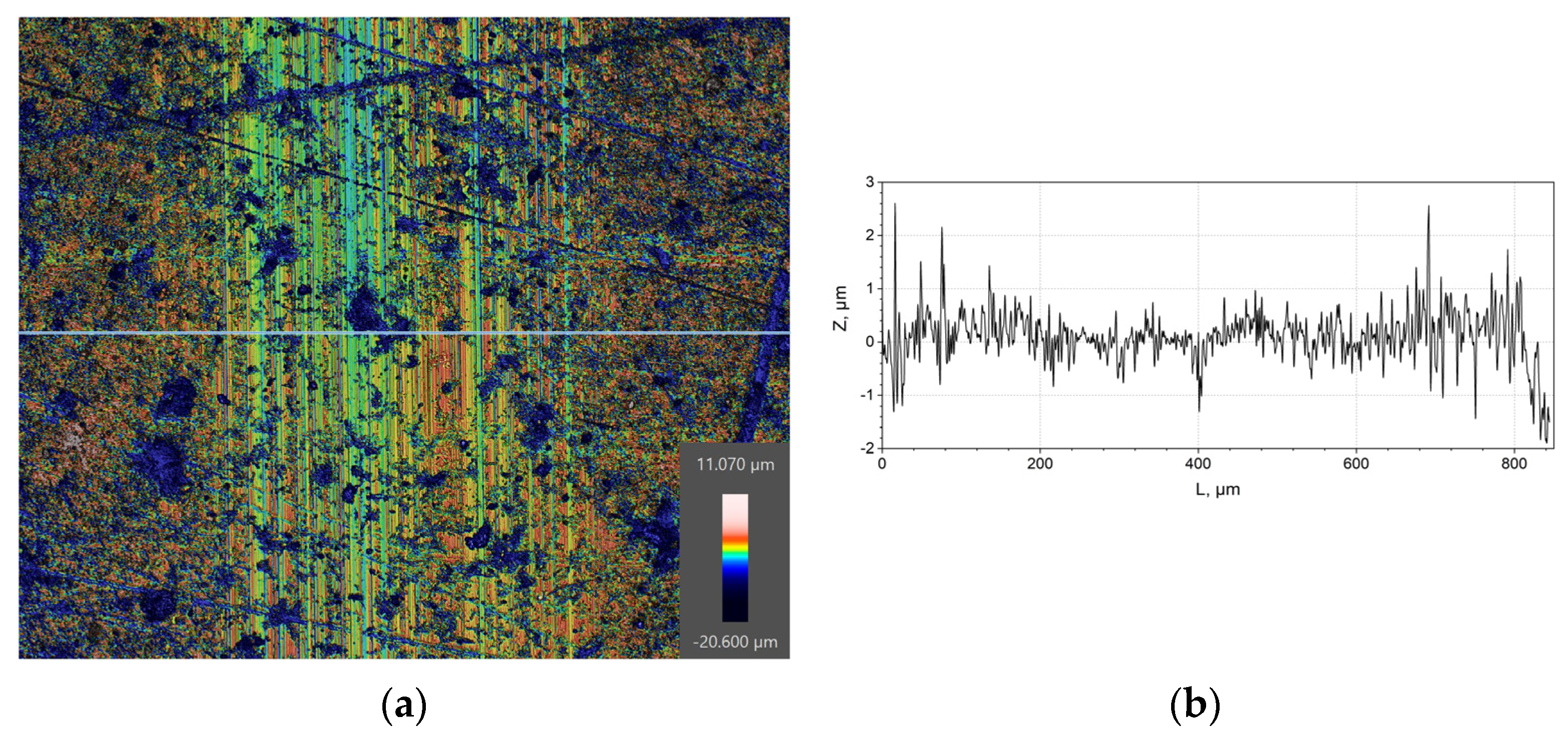
The friction track profile is shown in Figure 2 (the average friction coefficient was 0.19 [28]), and the change in the surface of the coated sample was analyzed. Below are the results for characteristic surface areas at the boundary and in the middle zone of the friction track.
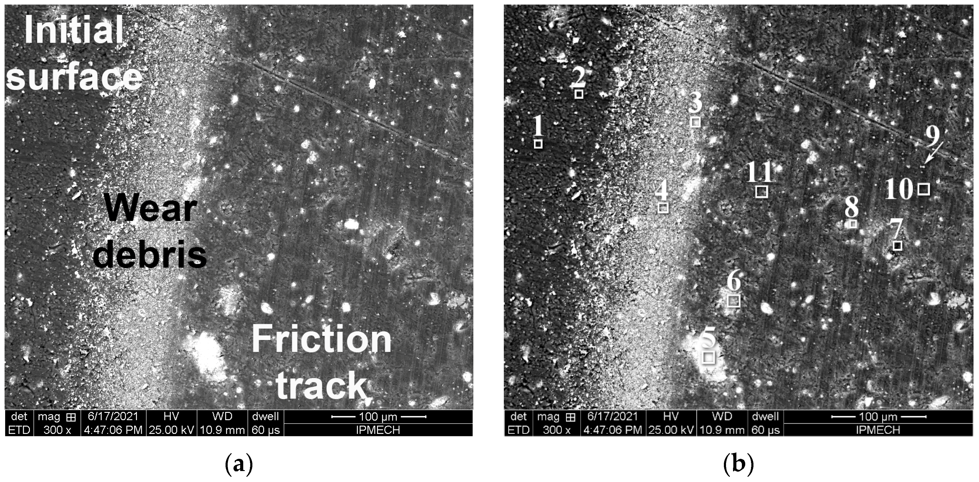
The image of the sample surface at the boundary of the upper edge of the friction track (area 1) and element distribution maps is shown in Figure 3, and the elemental composition of the characteristic zones is in Table 2. A graphical representation of the results, as done, for example, in [33], is inappropriate since it is impossible to predict the compositions of secondary structures.
Figure 3a shows the zones that most clearly differ in composition and topography—the edge of the friction track, a strip of a relatively dense layer of wear particles, and the initial surface of the coating. It should be taken into account that SEM gives the content of elements to a depth of approximately 3 µm. This means that not only the high-carbon diamond-like coating (C + Si) but also the nitrided sublayer ((Al, Si, Cr) N) and the composite base (W, Co, Cr, C) are analyzed. Therefore, a change in the content of these elements could be associated not only with their appearance on the friction surface but also with a change in the coating thickness, especially due to the existing growths or depressions in the friction zone and on the initial surface (light and gray zones).
Figure 3 shows that the zones mentioned above differ significantly in topography. The friction track is smoother than the original surface and has risks in the direction of friction. It could be seen that on both surfaces there are defects in the form of pits of various shapes and sizes; moreover, the number of defects on the friction track was greater, and the defects themselves were larger. The wear particle zone is a light band consisting of many compact groups of small particles. The strip zone near the friction track is smoother compared to more distant zones.
The element distribution maps (Figure 3c) confirm that the wear strip consists mainly of iron oxides and was depleted in carbon and elements from the nitrided sublayer.
Spots with high nitrogen content in the friction track and in the zone without friction correspond to the presence of pits in the initial state of DLC, which increase in size as a result of friction.
For oxygen, in addition to wear products, individual points with increased content in the friction track and outside the friction track are characteristic. These points coincide with the points of increased iron content. These are iron oxide particles that did not interact with the carbon from the DLC.
In area 1, the compositions of zones 1–4 and 1–5 (see Table 2) obtained on the initial surfaces outside the friction track in zones without defects were taken as the initial ones. They are characterized by a high carbon content (65%–67%), a low oxygen content (0.4%–1.1%), heterogeneity in nitrogen (6.8%–13.9% N), cobalt (0.2%–0.6% Co) and tungsten (0.7%–3.7% W), the average content of aluminum (2%–3% Al), silicon (2%–3% Si), chromium (12%–16% Cr), as well as low content of iron (0.04%–0.06% Fe) and nickel (0.02% Ni). Iron and nickel are fine wear dust from the steel ball.
The chemical composition of the surface along the edge of the friction track (zones 1–8 and 1–10) differs slightly from the original surface of the DLC in terms of carbon content (61.5%–68.5%) and tends to decrease in nitrogen content. The main differences are the increase in the content of iron and nickel by 5 times, manganese by 1.3 times, and oxygen by 3 times. From Figure 2, it follows that the wear at the edge of the friction track was less than in the middle of the friction track. Along the edge of the friction track (zones 1–8 and 1–10), the interaction with the steel of the ball leads to the enrichment of secondary structures with elements of steel 52,100.
The decrease in the carbon content was caused by the presence of pits in the coating (zone 1–7—the original surface; zones 1–6, 1–9—friction track). In the process of friction, not only wear of the DLC occurs but also mechanical fracture. The coating partially delaminates, exposing the nitrided layer or tungsten-based substrate in these places. Mechanical failure was due to the presence of pits on the initial DLC surface, in some cases reaching the nitrided layer. The presence of tungsten in wear particles and on the friction surface means that, as a result of DLC chipping, the nitrided sublayer and substrate can also be destroyed [34,35]. On the friction track, the deeper the damage, the less carbon and more tungsten. In zone 1–6, DLC destroyed to a nitride sublayer (a maximum of nitrogen, aluminum, silicon, and chromium, which are part of the sublayer, was recorded). Depending on the location of the pit, a significant (zone 1–6) or insignificant (zone 1–7) amount of steel wear particles (0.26 and 0.05% Fe, respectively) are inside it. The probability of wear particles getting into the pits on the friction track is greater than outside the track. This was clearly seen in zone 1–9, which contains an increased amount of iron (1.36% Fe) and oxygen (1.99% O). This indicates the filling of zone 1–9 with wear particles of steel with carbon (46.07% C). Zone 1–9 was characterized by a minimum nitrogen content, which may mean that fracture of DLC and sublayer occurs. The increased carbon content indicates the subsequent filling of the pit with wear particles of the DLC. The depth of damage was evidenced by the anomalously high content of tungsten (up to 30.25%) and cobalt (8.0% Co) for area 1 and the low content of chromium (4.8%), which was less in the composite than in the nitride sublayer (up to 32%).
The wear particles that form the band (zones 1–1 and 1–2) are oxidized iron in composition (66%–71% Fe + 8.5%–12.3% O); that is, they are the result of steel ball wear.
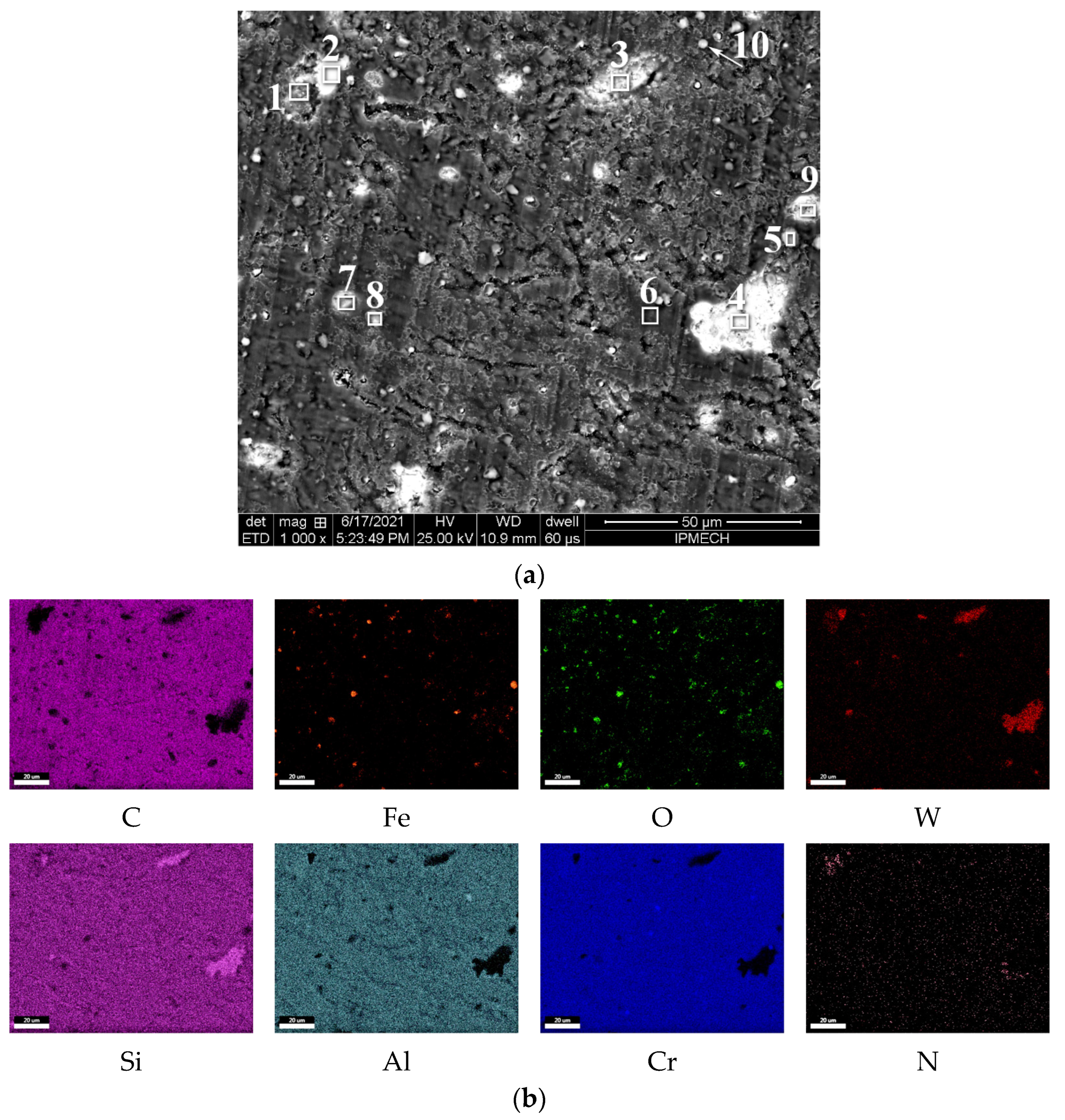
There was no dense layer of wear particles at the boundary of the friction track, but there were separate particles of different sizes (Figure 4).
According to the element distribution maps (Figure 4c), the wear particle strip contains iron, oxygen, and carbon. The oxygen content was less than in the wear strip in Figure 3. Iron oxides are located on the friction track and in the strip of wear products. The appearance of pits was noted on the friction trace. They have a high content of silicon and tungsten or aluminum and nitrogen. It depends on what is at the bottom of the pit; a nitrided sublayer or a substrate based on tungsten carbide. The tungsten carbide bottom pit contains steel ball wear particles (iron).
The elemental composition of various zones in this area is given in Table 3.
A comparative analysis showed that the topography and chemical composition of the zone outside the friction track (initial surface) of area 2 (2–1, 2–2) was almost identical to the similar zone of area 1 (1–4, 1–5). However, the layer of wear particles was much thinner, as determined by the amount of iron and oxygen. As the width of the friction track increases during the experiment, more wear particles come into direct contact with the steel ball. These particles become one of the components for the formation of secondary structures. At the friction surface, there were zones (2–10 and 2–11), which were very close in elemental composition to zones 1–8 and 1–10. This means that the secondary structures of areas 1 and 2 were characterized by an increased content of steel ball particles and oxygen compared to the initial surface. On the surface of the sample in area 2 (similar to zones 1–6 and 1–9), there are pits in the coating filled with ball wear particles (zones 2–5, 2–6, and 2–8).
More significant changes in the surface of the sample were found in the middle zone of the friction track (area 3, Figure 5, Table 4).
This area is characterized by a combination of smooth surface zones with large and small pits filled with wear particles. Separate steel particles embedded in the DLC have been identified. The average carbon content in different zones of area 3 was lower than in areas 1 and 2. This is due to the fact that the wear of the coating in the middle was greater than at the edges of the friction track (Figure 2). The least wear and, accordingly, the maximum carbon content was observed on smooth surfaces (zone 3–6). Compared to the initial state, the carbon content decreased by 9%–12%.
It follows from the element distribution maps (Figure 5b) that this area contains three large pits (about 20 µm in size) and several small pits (about 3 µm in size). The bottom of one large pit is a nitrided sublayer (enrichment with aluminum and nitrogen). The bottom of the other two large pits is a tungsten-based substrate (enriched with tungsten and silicon). It should be noted that in large pits, there were no wear products of the steel ball. Small pits were covered with wear products of the steel ball-particles of iron oxides.
In zones 3–3 and 3–4 (Table 4), there was no nitrogen, and the content of tungsten was maximum. This corresponds to DLC damage zones reaching the WC-based substrate. The resulting voids were filled with wear products of the DLC and the steel ball. The carbon content was 23%–32%. The silicon content was about 6%. The iron content was about 0.7%. This is the result of filling voids with wear products of the steel ball and DLC coating. This is how the “healing” of DLC damages happens. The powder mixture of wear products can act as a damper to prevent the development of fatigue cracks.
Table 5 shows the average surface composition outside the friction zone and the composition of smooth surface areas in the middle of the friction zone. The increase in wear is associated with a decrease in DLC thickness. This leads to a decrease in the carbon content and an increase in the content of tungsten and nitrogen, as noted in the analysis of the composition. That is why the relative wear of different zones is determined by the carbon, nitrogen, and tungsten content.
After friction in the secondary structures, the content of steel ball elements increased noticeably: nickel (4.7 times), iron (3.3 times), and copper (6.5 times). The enrichment of the friction surface with these elements means that they help to reduce DLC wear.
A noticeable increase in the content of the substrate elements in the secondary structures takes place: cobalt (3.1 times) and tungsten (2.8 times). Such an increase in the content of substrate elements cannot be explained by a decrease in the thickness of the DLC layer by 10%; there was an increase in the content of these elements on the friction surface. Cobalt and tungsten get into the secondary structures not as a result of friction but as a result of fracture of the DLC layer and the substrate. Cobalt is distributed evenly over the friction surface as a result of friction, which means that it helps to reduce DLC wear. The pits on the friction surface are enriched with tungsten; tungsten carbide is the cause of the pits. Therefore, it could be assumed that it increased wear.
It should be noted that despite the decrease in nitrogen content, the content of aluminum, silicon, and chromium, which are part of the nitrided layer, increased by 1.3 times. These elements get on the friction surface not as a result of friction but as a result of fracture of the DLC layer and the nitrided layer. The relatively uniform distribution of these elements over the friction surface means that they help reduce DLC wear.
According to [28], DLC wear significantly increases during the transformation of diamond-like structures into graphite-like structures. This allows us to assume that a similar transformation occurred on the friction surface with intense wear (about 50%). As a result, the surface has become softer, and for “self-preservation,” it requires a greater content of elements that help reduce wear. Secondary structures on the DLC surface can contain elements of the atmosphere (oxygen), C, Si, steel ball elements (Fe, Cr, Mn, Cu, Ni), substrate elements (W, Co, Cr), and nitrided layer elements (N, Cr, Al, Si). It should be noted that the content of nickel and manganese in the secondary structures significantly exceeds the content of iron. The content of manganese and nickel in the ball was two orders of magnitude less than the content of iron. Therefore, we can speak about the predominant transfer of these elements to secondary structures. The same could be said about chromium, but it is present in the substrate and in the nitrided layer, so it is impossible to accurately determine its origin in secondary structures.
The presence of a large number of different pits indicates that the coating was not so much gradually worn out as it was destroyed. The resulting pits were filled with steel and DLC wear particles, and the few pits were traps for relatively large steel particles (zones 3–5, 3–8, and 3–10). Some of the pits reach in depth up to the nitride sublayer (zone 3–1), and the largest ones almost reach the tungsten phases in the substrate (zones 3–3, 3–4, and 3–7). Possibly, there is an insufficient bonding strength of the nitride sublayer with phases with a high content of tungsten (tungsten carbide). All zones of the surface of area 3 were characterized by a higher iron content compared to areas 1 and 2. This indicates a significant effect of iron on the formation of secondary structures on the friction surfaces of the DLC. In this case, the most favorable secondary structure (zones of minimum wear) contained the minimum amount of oxygen, i.e., it provides a minimum level of oxidative wear. The ingress of particles of nitrides from the nitrided sublayer or carbides from the substrate into the secondary structures leads to increased wear.
Chemical analysis of the friction surface of the steel ball showed that the reaction of steel to friction was a decrease in the silicon content (compared to the initial composition) with a significant increase in the content of carbon and oxygen. The change in the content of nitrogen, chromium, nickel, and copper was negligible. The most interesting was the anomalously high (up to 7.2%) fluorine content on the friction surface of the steel ball. Usually, the fluorine content on steel after friction does not exceed 2%. It should be noted that fluorine was not found on the surfaces before friction.

4. Conclusions

Secondary structures on the friction surface of the sample with DLC, formed during dry friction with a ball of 52,100 steel, appear mainly as a result of saturation of the carbon phase with elements of the steel ball and their oxides. The content of iron oxides on the friction track decreased with the distance from the band of wear particles. Nickel, manganese, chromium, aluminum, and silicon were transferred to the secondary structures. Their source was not only steel wear particles but also coating and nitrided substrate particles. The pits formed during friction on the surface of the coating were filled with all types of wear particles and can also be traps for relatively large separated particles. This process of “healing” of damages with wear particles contributed to the supply of secondary structures with the necessary elements and prevented the development of fatigue failures in stress concentration zones.
Secondary structures formed on graphite-like and diamond-like coating components had different wear and composition. On graphite-like components, secondary structures contained more nickel, oxygen, and manganese compared to secondary structures on diamond-like components. Ball elements (Mn, Ni, Cr) in the friction zone helped to reduce DLC wear. Elements that enter the friction zone as a result of the destruction of the DLC, nitrided sublayer (aluminum and silicon nitrides), and substrate (WC, Cr3O2) contributed to an increase in DLC wear.

Author Contributions

Conceptualization, I.G. and T.M.; methodology, A.M. and I.S.; experiment, I.S. (friction tests), O.S. and T.M.; formal analysis, G.F.R., I.G. and J.L.E.; writing—original draft preparation, E.T.; writing—review and editing, E.T., S.F., G.F.R., A.M. and J.L.E.; visualization, O.S.; supervision, T.M.; project administration, I.S. and I.G. All authors have read and agreed to the published version of the manuscript.

Funding

This research was funded by a grant from the Russian Science Foundation (project No. 21-79-30058) (The concept of the article, microscopic studies, tribological tests, interpretation.); PID2021-128727OB-I00 Grant from Spanish Ministry of Science and Innovation (MICINN) (DLC coating technology).

Institutional Review Board Statement

Not applicable.

Informed Consent Statement

Not applicable.

Data Availability Statement

Data sharing is not applicable to this article.

Conflicts of Interest

The authors declare no conflict of interest.

References

  1. Rogachev, A.V.; Sidorskiy, S.S. Restoration and Increase of Wear Resistance of Machine Parts; BelTU: Belarus, Gomel, 2005; 343p. [Google Scholar]
  2. Aisenberg, S.; Chabot, R. Ion-Beam Deposition of Thin Films of Diamondlike Carbon. J. Appl. Phys. 1971, 42, 2953–2958. [Google Scholar] [CrossRef]
  3. Lettington, A.H. Applications of diamond-like carbon thin films. Carbon 1998, 36, 555–560. [Google Scholar] [CrossRef]
  4. Memming, R.; Tolle, H.J.; Wierenga, P.E. Properties of polymeric layers of hydrogenated amorphous carbon produced by a plasma-activated chemical vapour deposition process II: Tribological and mechanical properties. Thin Solid Film. 1986, 143, 31–41. [Google Scholar] [CrossRef]
  5. Grill, A. Tribology of diamondlike carbon and related materials: An updated review. Surf. Coat. Technol. 1997, 94–95, 507–513. [Google Scholar] [CrossRef]
  6. Tyagi, A.; Walia, R.S.; Murtaza, Q.; Pandey, S.M.; Tyagi, P.K.; Bajaj, B. A critical review of diamond like carbon coating for wear resistance applications. Int. J. Refract. Met. Hard Mater. 2019, 78, 107–122. [Google Scholar] [CrossRef]
  7. Martins, P.S.; Magalhães, P.A.A.; Carneiro, J.R.G.; Talibouya Ba, E.C.; Vieira, V.F. Study of Diamond-Like Carbon coating application on carbide substrate for cutting tools used in the drilling process of an Al–Si alloy at high cutting speeds. Wear 2022, 498–499, 204326. [Google Scholar] [CrossRef]
  8. Robertson, J. Diamond-like amorphous carbon. Mater. Sci. Eng. R 2002, 37, 129–281. [Google Scholar] [CrossRef] [Green Version]
  9. Plotnikov, V.A.; Dem’yanov, B.F.; Yeliseeyev, A.P.; Makarov, S.V.; Zyryanova, A.I. Structural state of diamond-like amorphous carbon films, obtained by laser evaporation of carbon target. Diam. Relat. Mater. 2019, 91, 225–229. [Google Scholar] [CrossRef]
  10. Meng, W.J.; Meletis, E.I.; Rehn, L.E.; Baldo, P.M. Inductively coupled plasma assisted deposition and mechanical properties of metal-free and Ti-containing hydrocarbon coatings. J. Appl. Phys. 2000, 87, 2840–2848. [Google Scholar] [CrossRef]
  11. Jacob, W.; Möller, W. On the structure of thin hydrocarbon films. Appl. Phys. Lett. 1993, 63, 1771–1773. [Google Scholar] [CrossRef]
  12. Grill, A. Diamond-like carbon: State of the art. Diam. Relat. Mater. 1999, 8, 428–434. [Google Scholar] [CrossRef]
  13. McKenzie, D.R.; Muller, D.; Pailthorpe, B.A. Compressive-Stress-Induced Formation of Thin-Film Tetrahedral Amorphous Carbon. Phys. Rev. Lett. 1991, 67, 773–776. [Google Scholar] [CrossRef] [PubMed]
  14. Grill, A.; Meyerson, B. Development and Status of Diamondlike Carbon. In Synthetic Diamond: Emerging CVD Science and Technology; Spear, K.E., Dismukes, J.P., Eds.; Wiley: New York, NY, USA, 1994; pp. 91–143. [Google Scholar]
  15. Donnet, C.; Erdemir, A. Tribology of Diamond-Like Carbon Films: Fundamentals and Applications; Springer: New York, NY, USA, 2008; 673p. [Google Scholar]
  16. Wang, K.; Zhou, H.; Zhang, K.; Liu, X.; Feng, X.; Zhang, Y.; Chen, G.; Zheng, Y. Effects of Ti interlayer on adhesion property of DLC films: A first principle study. Diam. Relat. Mater. 2021, 111, 108188. [Google Scholar] [CrossRef]
  17. Xiao, Y.; Shi, W.; Han, Z.; Luo, J.; Xu, L. Residual stress and its effect on failure in a DLC coating on a steel substrate with rough surfaces. Diam. Relat. Mater. 2016, 66, 23–25. [Google Scholar] [CrossRef]
  18. Liang, J.H.; Milne, Z.; Rouhani, M.; Lin, Y.-P.; Bernal, R.A.; Sato, T.; Carpick, R.W.; Jeng, Y.R. Stress-dependent adhesion and sliding-induced nanoscale wear of diamond-like carbon studied using in situ TEM nanoindentation. Carbon 2022, 193, 230–241. [Google Scholar] [CrossRef]
  19. Dimigen, H.; Hübsch, H.; Memming, R. Tribological and electrical properties of metal-containing hydrogenated carbon films. Appl. Phys. Lett. 1987, 50, 1056–1058. [Google Scholar] [CrossRef]
  20. Qiang, L.; Zhang, B.; Zhou, Y.; Zhang, J. Improving the internal stress and wear resistance of DLC film by low content Ti doping. Solid State Sci. 2013, 20, 17–22. [Google Scholar] [CrossRef]
  21. Chang, Y.; Wang, D.; Wu, W. Catalysis effect of metal doping on wear properties of diamond-like carbon films deposited by a cathodic-arc activated deposition process. Thin Solid Film. 2002, 420–421, 241–247. [Google Scholar] [CrossRef]
  22. Gayathri, S.; Kumar, N.; Krishnan, R.; Ravindran, T.R.; Amirthapandian, S.; Dash, S.; Tyagi, A.K.; Sridharan, M. Influence of transition metal doping on the tribological properties of pulsed laser deposited DLC films. Ceram. Int. 2015, 41, 1797–1805. [Google Scholar] [CrossRef]
  23. Orrit-Prat, J.; Bonet, R.; Ruperez, E.; Punset, M.; Ortiz-Hernandez, M.; Guillem-Marti, J.; Lousa, A.; Cano, D.; Diaz, C.; Garci Fuentes, G.; et al. Bactericidal silver-doped DLC coatings obtained by pulsed filtered cathodic arc co-deposition. Surf. Coat. Technol. 2021, 411, 126977. [Google Scholar] [CrossRef]
  24. Murata, Y.; Choo, C.-K.; Ono, H.; Nagai, Y.; Tanaka, K. Characterization of N-doped DLC Thin Films Prepared by Hydrocarbons Pyrolysis Method. Mater. Today Proc. 2016, 3, 197–202. [Google Scholar] [CrossRef]
  25. Xiao, Y.; Sun, W.; Ma, M.; Jia, Y.-P.; Liu, J.; Zhang, T. Microstructure, wear and corrosion behavior of nano-CeO2 doped diamond-like carbon (DLC) composite films. Diam. Relat. Mater. 2022, 126, 109087. [Google Scholar] [CrossRef]
  26. Hofmann, D.; Kunkel, S.; Bewilogua, K.; Wittorf, R. From DLC to Si-DLC based layer systems with optimized properties for tribological applications. Surf. Coat. Technol. 2013, 215, 357–363. [Google Scholar] [CrossRef]
  27. Baia Neto, A.L.; Santos, R.A.; Freire, F.L., Jr.; Camargo, S.S., Jr.; Carius, R.; Finger, F.; Beyer, W. Relation between mechanical and structural properties of silicon-incorporated hard a-C:H films. Thin Solid Film. 1997, 293, 206–211. [Google Scholar] [CrossRef]
  28. Gershman, I.; Mironov, A.; Mezrin, A.; Torskaya, E.; Kuznetsova, T.; Lapitskaya, V.; Rogachev, A. Effect of sp3–sp2 Transformation on the Wear Rate of the DLC Coating. Lubricants 2022, 10, 85. [Google Scholar] [CrossRef]
  29. Weicheng, K.; Zhou, Y.; Jun, H. Effect of carburizing treatment on microstructural, mechanical and tribological performances of Cr doped DLC coating deposited on Ti6Al4V alloy. Ceram. Int. 2021, 47, 34425–34436. [Google Scholar] [CrossRef]
  30. Li, A.; Chen, Q.; Wu, G.; Wang, Y.; Lu, Z.; Zhang, G. Probing the lubrication mechanism of multilayered Si-DLC coatings in water and air environments. Diam. Relat. Mater. 2020, 105, 107772. [Google Scholar] [CrossRef]
  31. Kim, J.-I.; Lee, W.-Y.; Tokoroyama, T.; Murashima, M.; Umehara, N. Tribo-chemical wear of various 3d-transition metals against DLC: Influence of tribo-oxidation and low-shear transferred layer. Tribol. Int. 2023, 177, 107938. [Google Scholar] [CrossRef]
  32. Kuznetsova, T.; Lapitskaya, V.; Khabarava, A.; Trukhan, R.; Chizhik, S.; Torskaya, E.; Mezrin, A.; Fedorov, S.; Rogachev, A.; Warcholinski, B. Silicon addition as a way to control properties of tribofilms and friction of DLC coatings. Appl. Surf. Sci. 2023, 608, 155115. [Google Scholar] [CrossRef]
  33. Arief, I.; Mukhopadhyay, P.K. Yielding behavior and temperature-induced on-field oscillatory rheological studies in a novel MR suspension containing polymer-capped Fe3Ni alloy microspheres. J. Magn. Magn. Mater. 2017, 429, 236–240. [Google Scholar] [CrossRef]
  34. Guo, T.; Chen, Y.; Cao, R.; Pang, X.; He, J.; Qiao, L. Cleavage cracking of ductile-metal substrates induced by brittle coating fracture. Acta Mater. 2018, 152, 77–85. [Google Scholar] [CrossRef]
  35. Guo, T.; Qiao, L.; Pang, X.; Volinsky, A.A. Brittle film-induced cracking of ductile substrates. Acta Mater. 2015, 99, 273–280. [Google Scholar] [CrossRef]
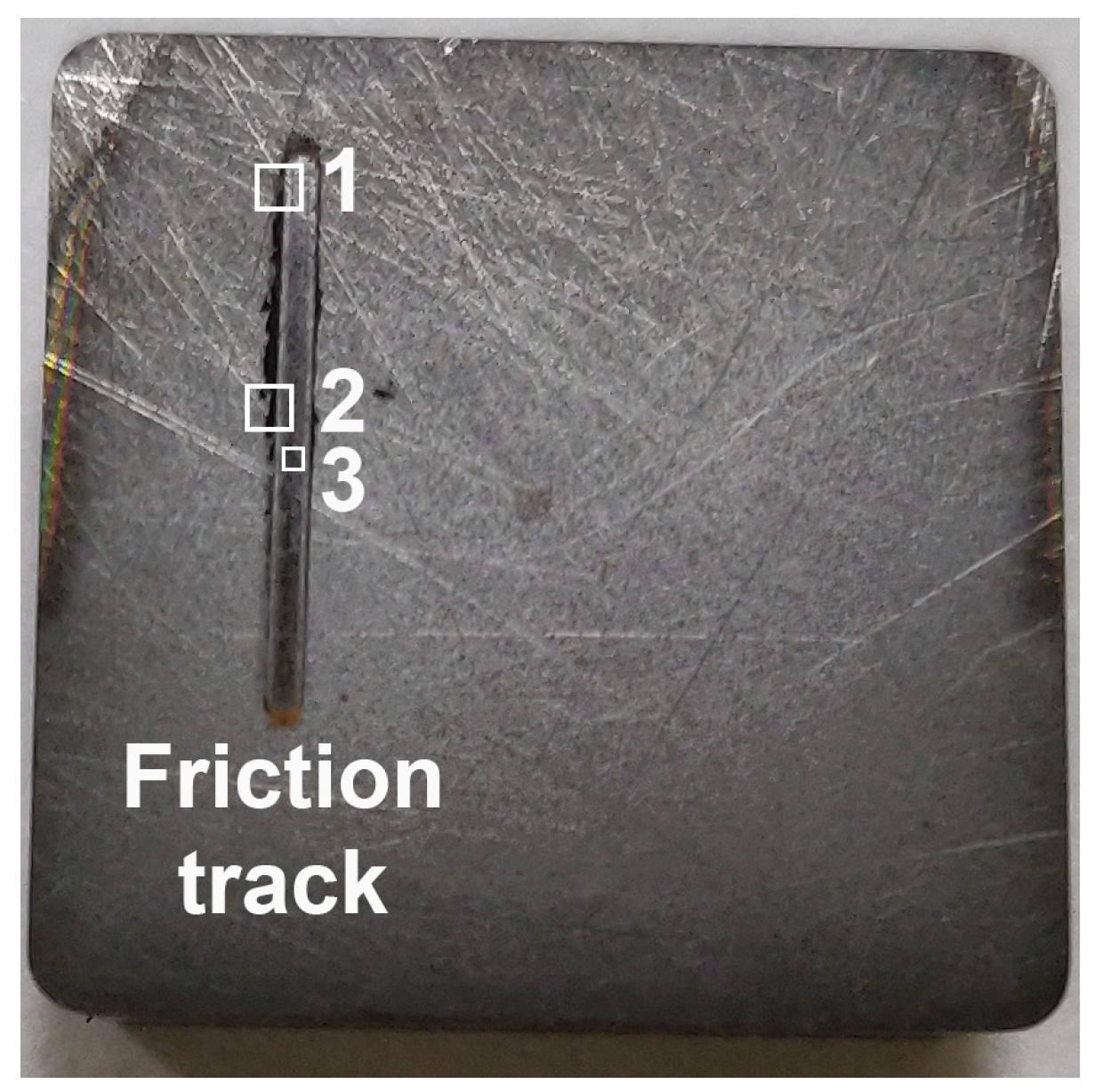
Figure 1. Coated sample after friction tests (numbers indicate the areas under study).
Coatings 12 01685 g001
Figure 2. Photo (a) and profile (b) of the sample surface after the test.
Coatings 12 01685 g002
Figure 3. Image of the sample surface in area 1 at the boundary of the friction track: (a)—characteristic zones, (b)—zones of X-ray spectral analysis, (c)—maps of the distribution of chemical elements.
Coatings 12 01685 g003
Figure 4. Image of the sample surface in area 2 at the boundary of the friction track: (a)—characteristic zones, (b)—zones of X-ray spectral analysis, (c)—maps of the distribution of chemical elements.
Coatings 12 01685 g004aCoatings 12 01685 g004b
Figure 5. Image of the sample surface in area 3 in the middle zone of the friction track: (a)—zones of X-ray spectral analysis, (b)—maps of the distribution of chemical elements.
Coatings 12 01685 g005
Table 1. Chemical composition (wt.%) of 52,100 steel.
CSiMnNiSPCrCuFe
0.95–1.050.17–0.370.2–0.4up to 0.3up to 0.02up to 0.0271.3–1.65up to 0.25bal.
Table 2. The chemical composition of the sample surface zones in area 1 (the edge of the friction track, the strip of wear products, and the coating outside the friction zone).
ZoneContent of Element, wt.%
NOAlSiCrMnFeNiCuCoWCOther
1–11.7712.290.450.235.040.6965.800.230.044.530.728.16bal.
1–21.038.450.220.514.740.6571.060.230.044.790.717.52bal.
1–36.040.433.453.8217.601.020.050.020.010.650.8765.78bal.
1–46.770.403.243.3015.900.970.040.020.010.573.6764.91bal.
1–513.891.112.021.9611.880.760.060.020.020.220.7067.29bal.
1–616.731.9110.405.2632.762.230.260.210.063.7817.957.44bal.
1–711.441.568.975.7731.961.710.050.060.003.1020.8013.73bal.
1–84.841.243.023.7517.431.180.260.110.081.154.7661.87bal.
1–90.031.990.373.664.480.711.360.640.378.0030.2546.07bal.
1–104.671.213.703.8317.771.100.190.050.020.824.8461.52bal.
Table 3. Elemental composition of different zones of the sample surface in area 2 (edge of the friction track, band of wear particles, DLC outside the friction zone).
ZoneContent of Element, wt.%
NOAlSiCrMnFeNiCuCoWCOthers
2–19.431.072.552.9512.270.730.050.020.020.191.6968.93bal.
2–24.690.283.383.7116.661.070.080.050.030.724.4264.68bal.
2–314.8518.274.522.1612.591.0523.660.030.021.420.9520.39bal.
2–43.882.393.204.0618.341.261.360.060.030.824.9059.49bal.
2–50.312.340.565.203.140.351.350.350.076.6933.2444.92bal.
2–612.971.619.605.4832.312.260.420.260.123.4320.949.32bal.
2–70.122.584.514.2622.761.791.010.260.203.6019.9037.84bal.
2–80.032.140.005.651.530.150.660.150.013.9966.8216.26bal.
2–93.1917.182.472.3216.901.6120.220.070.021.651.8232.43bal.
2–103.620.604.053.6118.341.250.200.130.101.766.7659.13bal.
2–115.580.483.403.0216.181.040.100.080.031.125.0363.68bal.
Table 4. Elemental composition of the sample surface in area 3 in the middle zone of the friction track.
ZoneContent of Element, wt.%
NOAlSiCrMnFeNiCuCoWCOthers
3–115.931.819.366.0527.941.830.210.240.044.4021.719.59bal.
3–20.9710.870.364.524.520.745.620.330.284.7149.6814.84bal.
3–30.001.490.325.552.220.340.780.270.124.1650.0732.54bal.
3–40.021.780.035.861.500.200.740.250.054.5559.8122.91bal.
3–51.5625.181.552.716.250.7629.200.150.053.057.9821.15bal.
3–63.190.253.833.8218.291.260.200.140.131.337.4459.57bal.
3–70.580.980.425.304.880.610.600.420.177.4550.8825.24bal.
3–83.3918.223.773.4414.471.2512.040.080.031.624.9236.53bal.
3–95.552.581.964.885.960.720.520.380.204.8642.1428.03bal.
3–103.5119.402.832.9414.731.2911.930.050.031.192.8039.15bal.
Table 5. Comparison of the compositions of secondary structures with the initial surface.
ZoneContent of Element, wt.%
NOAlSiCrMnFeNiCuCoWOthersC
Average composition of the initial surface8.70.722.82.9814.180.880.060.030.020.432.620.1566.45
Secondary structures with wear near 10%3.190.253.833.8218.291.260.200.140.131.337.440.5559.57
Secondary structures with wear near 85%15.931.819.366.0527.941.830.210.240.044.421.710.899.59
Publisher’s Note: MDPI stays neutral with regard to jurisdictional claims in published maps and institutional affiliations.