Article

Investigations on Additively Manufactured Stainless Bearings

by
Timm Coors
1,*,
Mohamad Yusuf Faqiri
2,
Felix Saure
1,
Christoph Kahra
2,
Christoph Büdenbender
3,
Julius Peddinghaus
3,
Vannila Prasanthan
4,
Florian Pape
1,
Thomas Hassel
2,
Sebastian Herbst
2,
Florian Nürnberger
2,
Hendrik Wester
3,
Johanna Uhe
3,
Bernd Breidenstein
4,
Berend Denkena
4,
Bernd-Arno Behrens
3,
Gerhard Poll
1 and
Hans Jürgen Maier
2
1
Institute for Machine Design and Tribology, Leibniz University Hannover, An der Universität 1, 30823 Garbsen, Germany
2
Institute for Materials Science, Leibniz University Hannover, An der Universität 2, 30823 Garbsen, Germany
3
Institute for Forming Technology and Machines, Leibniz University Hannover, An der Universität 2, 30823 Garbsen, Germany
4
Institute for Production Engineering and Machine Tools, Leibniz University Hannover, An der Universität 2, 30823 Garbsen, Germany
*
Author to whom correspondence should be addressed.
Coatings 2022, 12(11), 1699; https://doi.org/10.3390/coatings12111699
Submission received: 26 September 2022 / Revised: 2 November 2022 / Accepted: 3 November 2022 / Published: 8 November 2022

Abstract

:
Additive manufacturing with multi-material design offers great possibilities for lightweight and function-integrated components. A process chain was developed in which hybrid steel–steel-components with high fatigue strength were produced. For this, a material combination of stainless powder material Rockit® (0.52 wt.% C, 0.9% Si, 14% Cr, 0.4% Mo, 1.8% Ni, 1.2% V, bal. Fe) cladded onto ASTM A572 mild steel by plasma arc powder deposition welding was investigated. Extensive material characterization has shown that defect-free claddings can be produced by carefully adjusting the welding process. With a tailored heat treatment strategy and machining of the semi-finished products, bearing washers for a thrust cylindrical roller bearing were produced. These washers showed a longer fatigue life than previously produced bearing washers with AISI 52100 bearing steel as cladding. It was also remarkable that the service life with the Rockit® cladding material was longer than that of conventional monolithic AISI 52100 washers. This was reached through a favourable microstructure with finely distributed vanadium and chromium carbides in a martensitic matrix as well as the presence of compressive residual stresses, which are largely retained even after testing. The potential for further enhancement of the cladding performance through Tailored Forming was investigated in compression and forging tests and was found to be limited due to low forming capacity of the material.

1. Introduction

The load of machine elements like bearings is mostly concentrated in a small volume. In the contact region of the rolling contacts, the material is subjected to very high surface pressures in the GPa range. These surface pressures lead to high cyclic stresses in the layer close to the surface. When the rolling elements run on the bearing raceway for more than 106 and up to 1010 cycles, rolling contact fatigue (RCF) can possibly lead to failure of the component. At sufficient depth, the damage relevant stresses decrease to a lower level. To achieve a sufficient fatigue lifetime, the highly loaded material volume must have high toughness and a fine grained microstructure with few material defects like pores or inclusions. In addition to the material quality, the material selection for highly loaded tribological contacts are crucial. In particular, AISI 52100 has long been established as a favourable material for rolling bearing applications [1]. The production of bearing components from this material was constantly improved through decades of research and development [2]. Component failures due to material defects are therefore rare [3]. However, this also means that the potential for further optimization is rather low. In addition, there are applications where the use of AISI 52100 or similar steels is not possible. Reasons can be the material availability in large dimensions or specific requirements of the respective applications, such as corrosion resistance, temperature resistance or durability under special events like impacts or overloads [4].
To overcome this, new materials and manufacturing strategies have to be developed. Recently, additive manufacturing (AM) strategies for metallic rolling element bearings have emerged. Due to limitations of AM and the high requirements of rolling bearings as high precision machine elements, the applications are limited [5,6]. AM is more commonly used for plain bearings, see for example [7,8,9,10]. However, as early as 1998, Hetzner described in an outlook that lifetime increases in rolling bearings could be achieved by laser cladding of a high-performance material onto a base material [11]. This opens up the possibility of achieving a higher performance of alloys and components than is possible with previous steel production technologies. This process has not yet become part of the state-of-the-art. Recent publications in this area are mostly dealing with process development, research into microstructure and investigations on model test rigs [12,13,14,15,16]. Another field for buildup-welded materials by AM is the repair of worn machine elements such as shafts or bearings [17,18,19]. As actual bearing components, Tate et al. used AM to manufacture stainless steel (AISI 316L) cages [20]. Tolerances and surface finish turned out to be difficult without machining. Mirring et al. investigated a selective laser melting process for M50NiL bearing outer rings with integrated cooling channels [21]. It was shown by ball-on-rod tests at a Hertzian pressure of 5.5 GPa, that the RCF performance of AM rods was at least comparable to conventionally manufactured rods. The AM technology was described as promising because of potential weight reduction, functional integration and performance gains.
In earlier publications, a process chain called Tailored Forming was introduced [22]. In this method, high strength steels are employed in the highly stressed zones, e.g., the raceway of a bearing, and a low-alloyed and low-cost steel for the remaining areas. Significant improvements in terms of ecological and economical efficiency can be reached by limiting the application of alloyed high-performance steels to the highly loaded component areas. By combining deposition welding with subsequent hot forging, a load-adapted hybrid steel semi-finished product can be produced. In earlier work, bearing races of different materials following the Tailored Forming process chain have been manufactured. Behrens et al. found that thermomechanical treatment of a welded specimen had an positive impact on microstructure and mechanical properties of the weld [22]. Pape et al. [23] investigated wire-based laser metal deposition welding of AISI HNV3 (material number: 1.4718) high-alloy steel onto sheets of ASTM A283 (1.0038). The semi-finished workpiece was subsequently die forged. These parts were used as races for cylindrical roller thrust bearings, and a general feasibility of the concept could be shown. No delaminations of the cladding or other structural damages were observed. The Tailored Forming bearings failed due to rolling contact fatigue and achieved a lower life time than standard AISI 52100 (1.3505) bearings. Based on this, Behrens et al. manufactured Tailored Forming bearing washers by welding AISI 5410 (1.7035) on low carbon steel using plasma transferred arc welding (PTA) and subsequent forming [24]. AISI 5410 features a higher hardness than the previously used cladding material. It was expected that this would result in better performance in bearing fatigue tests. The results were compared to AISI 5410 cladded bearings that did not undergo subsequent forming and again to conventional standard bearings. It was found that the subsequent forming significantly increased the fatigue life by closing pores that lead to early failures. However, Tailored Forming bearings achieved a fatigue life of 85% of the conventional bearings made from AISI 52100. It was expected that by further improvement of the processes and by using higher strength cladding materials, the fatigue life of the conventional bearings would be reached or even exceeded. To investigate this, Coors et al. employed PTA to weld atomized bearing steel AISI 52100 to low carbon steel [25]. Due to the higher strength, welding defects could not be completely eliminated through subsequent hot forming. Nevertheless, the service life of the AISI 52100 Tailored Forming washers significantly exceeded that of the two previously tested series [23,24]. It was found that welding defects lead to failure of those bearings. By further optimizing the welding and forming processes, even higher fatigue life should be possible. Further improvement in component performance seems possible, in particular through process improvement with a focus on high-performance materials. So far, however, no promising material has been identified for this application.

2. Materials and Methods

2.1. Aims

Based on the previously described results, the following research hypothesis is made: By developing a more weldable high-strength material, a longer fatigue life of bearings produced by cladding processes can be achieved by a thorough analysis and optimization of the manufacturing process. The new material system to be developed is largely unknown in terms of its optimized production, its mechanical properties and its performance in fatigue life testing. As a further step towards increasing fatigue life, the Tailored Forming approach is also being investigated, in which the additively produced sample is subsequently formed. The following tasks of this work were therefore defined:
1
Design of a new material with the following requirements that can be processed by deposition welding as AM process:
(a)
Available and weldable powder for PTA welding.
(b)
Cladding with minimized porosity.
(c)
Minimum surface hardness of 56 HRC.
(d)
Better rolling contact fatigue performance than AISI 52100.
(e)
Corrosion resistance for special applications.
2
Characterization of the mechanical properties and microstructure of the material system after the different processing stages.
3
Determination and quantification of the potential using applied component tests, especially with respect to the current industry standard.
4
Investigation of Tailored Forming as a process to further increase performance by thermo-mechanical treatment and grain refinement.

2.2. Process Design

The previous mentioned aims were tested with experimental studies. To demonstrate the approach, bearing rings for a cylindrical roller thrust bearing were manufactured. As shown in Figure 1, two batches of samples were manufactured by deposition welding of a high-alloyed iron-based powder material called Rockit®. It is utilized by plasma transferred arc (PTA) welding on a disk of ASTM A572 (1.0045) low carbon steel. Rockit® and its welding process is further described in Section 2.3 and Section 2.4. The hybrid specimens were prepared by waterjet cutting for the subsequent processes. In order to obtain the optimum material properties and to produce the final geometry, heat treatment (Section 2.5) and machining (Section 2.6) were then carried out. Section 3 presents the results of the studies using the analytical methods presented in Section 2.8. As described above, strong emphasis was placed on material characterization in Section 2.8, with metallography, residual stress measurements and scanning acoustic microscopy being carried out. Finally, the fatigue life of the finished bearings is presented in Section 3.2.
A third batch of samples was welded to investigate the influence of a subsequent forging of the hybrid samples. Section 4 describes the forming process, following the Tailored Forming approach. The stress–strain behaviour of the Rockit® cladding was quantified with uniaxial compression tests.

2.3. Materials

Rockit® from supplier Höganäs AB, a manufacturer of metal powders for powder metallurgy, was identified as a promising material for AM of rolling bearing raceways due to its availability and material composition. So far, few findings on the application behaviour of this material are known in the literature. Saifo et al. investigated the microstructure and hardness of single layer and bilayer Fe-Cr-V coating produced by PTA process with Rockit® 706 and other ferrous based powders [26]. It was possible to produce a bilayer without cracks, and the hardness of the topcoat was decreased due to dilution of the interlayer. Qi et al. investigated and demonstrated the effects of vanadium additive on mechanical properties and tribological performance of high chromium cast iron hardfacing metal [27]. They showed that the microstructure of hardfacing metal is refined with the increase of vanadium additive and also that the vanadium additive improves the wear resistance. Olofsson et al. laser-cladded grey cast iron disc brake rotors with Rockit® 401 as a refurbishment [28]. The goal of the study to lower energy consumption and CO 2 footprint was reached. Nevertheless, it was found that wear and particle emission was higher for the laser-cladded samples compared to cast iron. Mahade et al. researched the dry sliding behaviour of high-velocity air fuel deposited coatings from Rockit® 401 against alumina balls [16]. They found that Rockit® 401 coatings offer good tribological properties with advantages over expensive alternatives such as hard chrome, WC or Cr 3 C 2 coatings. Vogt et al. investigated high-speed laser metal deposition welding of Rockit® 401 as a candidate for replacement of hard chromium plating. It was found that multiple layers were metallurgically bonded to the substrate and no bonding defects or cracks were detected. With high surface rates, a decrease of hardness of the cladding layer has been observed.
For the present study, Rockit® as cladding material was mixed from the powder alloys Rockit® 706 and Rockit® 401 (both from Höganäs AB, Höganäs, Sweden). Before the welding process started, the powders were mixed in a ratio of 1:5 in order to obtain a corrosion resistant alloy. Therefore, the content of chromium must be at least 12% [29]. Both powders have spherical grains with a grain size ranging from 53–150 µm [30]. Rockit® 401 is a highly alloyed ferritic–martensitic steel with a high chromium content and is said to be characterized by good wear and corrosion resistance [31]. Rockit® 706 is a high alloyed martensitic steel that is claimed to have high hardness, wear resistance and high impact strength [32]. The cladding materials were deposited on unalloyed steel plates made of ASTM A572. The diameter of the plate was 140 mm and had a thickness of 10 mm. The chemical composition of the plates and cladding material are shown in Table 1. The values for ASTM A572 and Rockit® cladding were determined after finishing with the spark spectrometer SPECTROMAXx (SPECTRO ANALYTICAL INSTRUMENTS GMBH). The values coincide with the pre-calculated mixing ratio of the powders Rockit 706® and Rockit 401®. The values for the accompanying elements are in accordance to the standard DIN EN 10088-3 [29].

2.4. Plasma Transferred Arc (PTA) Welding

To manufacture the hybrid bearing washers, PTA was used. PTA is a fusion welding process which can be applied for wear and corrosion resistant claddings on surfaces. During the welding process, a tungsten cathode creates a plasma arc to the anodic metal part with high energy density, which melts the surface of the base material. Simultaneously, the cladding material is inserted into the arc by a powder stream and becomes molten, resulting in a cladding base material. Argon is used as a transport, protective and plasma gas during the welding process. The welding torch was a PTR450 (Autogen-Ritter GmbH, München, Germany), and the PSI 400 (Kjellberg Finsterwalde GmbH, Finsterwalde, Germany) was used as the current source. For the welding process, a six-axis industrial robot (KUKA AG, Augsburg, Germany) was used, with two additional axes provided by a turn and tilt table. To obtain a clean surface, the samples were sandblasted and purged with acetone before the welding process started.
First, the welding was started from the centre to the edge of the disk with a slow welding speed of 0.1 m/min. This ensured a preheating of the disk and at the same time the welding parameters were increased constantly to avoid a blockage of the torch. After reaching the edge, the welding of the mono seam began. During the welding process, the torch oscillated with a frequency of 1 Hz and an amplitude of 3 mm and at the same time the turn and tilt table rotated around its own axis with a rotational speed of 72°/min. The oscillation increased the dynamics of the weld pool for degassing of the melt averting pores. In order to keep the dilution between the base and cladding metal constant, the welding current was dynamically adapted during the welding process. Therefore, the starting welding current of 220 A was gradually reduced to 180 A. After the turn and tilt table had rotated once, the welding was finished. The welding process takes 5.26 min, whereby the disc heats up to 700 °C. An overview of the welding parameters are given in Table 2. The experimental setup is shown in Figure 2.

2.5. Heat Treatment

After welding and pre-machining, a heat treatment consisting of quenching and tempering was carried out. This homogenizes the microstructure and adjusts the required strength and hardness of the bearing washers. The heat treatment was carried out in a hardening box, equipped with a thermocouple. After preheating the hardening box to 1030 °C in an electrical chamber furnace, the bearing washers were placed in the box together with neutral annealing coal to suppress surface decarburization. The bearing washers were austenitized at this temperature for 45 min (heating + holding time). To further prevent decarburization of the parts, argon was used. Quenching was carried out in an oil bath at room temperature. To reduce brittleness and internal stresses, the bearing washers were subsequently tempered at 150 °C for 1 h.

2.6. Machining

After heat treatment, the hybrid bearing washers were hard turned to the required final dimensions. The turning was carried out on a CNC 2-axis lathe of type NEF400 (Gildemeister DMG Mori Seiki AG, Bielefeld, Germany). An indexable insert of the type VBMT160408 MM 1 115 (Sandvik Tooling GmbH, Düsseldorf, Germany) was used for the final machining. For the hard turning process, a cutting speed of v c = 90 m/min, a feed rate of f = 0.1 mm and a depth of cut of a p = 0.3 mm were used. The machining was carried out with a cooling lubricant of the type Biowas EP1 (WASCUT Industrieprodukte GmbH, Sierksdorf, Germany). This is a watersoluble cooling lubricant (emulsion) based on a plant oil derivative. The final surface roughness was subsequently adjusted by a multi-step polishing process on a polishing device of type Tegramin-30 (Struers GmbH, Willich, Germany). Two different sandpapers with 220 and 500 grits were used in order to set the surface roughness. Through this process, the surface roughness was adjusted to the arithmetic mean roughness value of Ra = 0.14 µm required for the bearing fatigue tests.

2.7. Bearing Fatigue Testing

Bearing performance was tested on the finished parts in accordance with multiple previous investigations [23,24,25] on a modified FE8 test rig following DIN 51 819 [33]. Two cylindrical roller thrust bearings of type 81 212 are arranged in series in the FE8 test head. Each bearing consisted of a shaft washer, a housing washer and the rolling element set with cage between both washers. The shaft locating washer was press-fitted onto the test shaft, which was driven by an electric motor at constant speed levels. One housing washer was manufactured according to the method presented here and inserted in the test rig. The remaining washers and the rolling element set were industrially manufactured bearings made of AISI 52100. The operating parameters are summarized in Table 3. The testing force was applied in axial direction via a load cell and amounts between 60 kN and 80 kN in two stages for approval testing and accelerated life tests:
1
Base load with 60 kN at a shaft speed of 500 min 1 for 24 h as a running-in procedure and a further 226 h at 750 min 1 as life test. According to an industry standard [34], the test is considered as passed after 200 h.
2
Increased load with 80 kN at 500 min 1 if the first load stage was passed. The second stage was operated until failure of a bearing. In addition, the number of rolling elements was reduced to increase the Hertzian pressure from 1.8 GPa to 2.2 GPa. The load ratio (or dynamic load safety factor) C / P between the basic dynamic load rating of C = 137 kN and the actual equivalent dynamic load P increases from 2.28 to 1.35.
Failure of a bearing washer was monitored by a condition monitoring system, which stopped the test. As a shutdown criterion, a threshold of 150% of the steady state vibration signal has to be exceeded. The tests were operated with recirculating lubrication of Renolin CLP 68 (Fuchs Lubricants GmbH, Mannheim, Germany). Due to higher tribological loads in load step 2, the rotational speed was limited to 500 min 1 in order to not exceed temperatures of 100 °C. Following ISO 16,281 [35], the modified reference rating life for standard bearings has been calculated in Table 3.

2.8. Analytical Methods

2.8.1. Metallographic Investigations and Nanohardness Measurements

To investigate the influence of the welding process and the heat treatment on the microstructure and hardness, bearing washers were removed from the process chain after the respective process steps. To investigate the transition zone, cross sections were taken from the bearing washers in the radial direction. For the metallographic investigations, the samples were ground, polished and etched with 2% nitric acid solution and V2A-stain. Hardness measurements on an ATM Q10A+ (ATM, Qness GmbH, Mammelzen, Germany) were also carried out after each process step to determine the hardness distribution across the transition zone. Hardness profiles were measured according to Vickers HV0.5 standard from the surface of the bearing washer to the base material [36]. Scanning electron microscopy was carried out to characterize the element distribution in the transition zone. Energy dispersive X-ray (EDX) linescans and mappings of the transition zone were taken. To obtain a detailed distribution of the hardness in the substrate material, the transition zone and cladding steel nanohardness measurements were carried out. The Hysitron TriboIndenter TI 950 (Bruker, Minneapolis, MN, USA) with a possible force range of 2 µN to 10,000 µN was used for mapping of the nanohardness. All tests were carried out under laboratory conditions, with an ambient temperature of 17 ± 1 °C and a humidity of 38 ± 6%. A triangular Berkovich diamond tip with a tip radius of less than 50 nm was used to determine the nanohardness. The measuring field was divided into 5 × 5 fields. Each field has a dimension in x- and y-direction of 38 µm. Every measuring field was subdivided in an area where 20 × 20 measuring points were set. In summary, 10,000 indents were performed for the detailed hardness mapping. To perform the high amount of measuring points, the XPM unit of the Hysitron TriboIndenter was applied.

2.8.2. Residual Stress Measurement

Machining, as the last step in the process chain of hybrid bearing washer production, has a big influence on the final component properties [37]. In particular, the thermomechanical load during machining influences the resulting subsurface properties such as residual stresses. Machining induced residual stresses have a significant influence on the fatigue life of components [38,39,40,41,42,43]. For this reason, the determination and investigation of residual stresses is essential for understanding fatigue behaviour and life time. Therefore, a determination of residual stress depth profiles was carried out with the aid of X-ray diffraction measurement techniques. An established method is the angular dispersive X-ray residual stress determination using the sin 2 ψ -method. The residual stress measurements were performed on a two circle X-ray diffractometer type XRD 3003TT (Röntgenwerk Rich. Seifert & Co., Ahrensburg, Germany) with a Cr-tube as the anode material. A position sensitive detector was applied to detect the diffracted X-rays. For a more detailed description of the measurement settings during residual stress determination, reference is made to [25].

2.8.3. Scanning Acoustic Microscopy

By means of scanning acoustic microscopy (SAM) using the pulse-echo method, the samples were characterized on the basis of ultrasound images. Influences of the individual process steps on defects under the surface can be detected and examined. For this purpose, each sample was scanned with a SAM 301 (PVA TePla, Wettenberg, Germany) system in a basin with distilled water as a coupling medium. A thin layer of penetrating oil was used as a corrosion inhibitor on the specimen surface. The frequency of the transducer was 75 MHz with a focal distance of 12.7 mm in water. The detection limit was 6.7 µm at an axial resolution of 20 µm.

3. Results

3.1. Material Charactarization

3.1.1. Microstructure and Hardness

The metallographic results and hardness measurments after deposition welding and hardening are presented in Figure 3. After deposition welding, a typical needle-shaped Widmanstätten ferrite could be observed in the ASTM A572 base material (Figure 3a), due to the high cooling rate from austenitising temperature during solidification. The microstructure in the Rockit® cladding material contains a dendritic solidification structure with a carbide lattice at the former austenite grain boundaries. In the dilution zone, a thin layer without carbide accumulations was found. The micrographs after hardening are shown in Figure 3b. After hardening, the Widmanstätten structure in the base material was completely transformed to martensite. During heat treatment, the carbide lattice is partially dissolved due to diffusion processes, resulting in finely distributed carbides in the dentritic areas.
Using EDX mapping, increased concentrations of chromium and vanadium and a decreased concentratrion of iron were detected in the zones at the former austenite grain boundaries after PTA welding (Figure 4). This indicates the formation of chromium and vanadium carbides. Additionally, a slight increase of element concentrations were detected in the thin layer in the dilution zone.
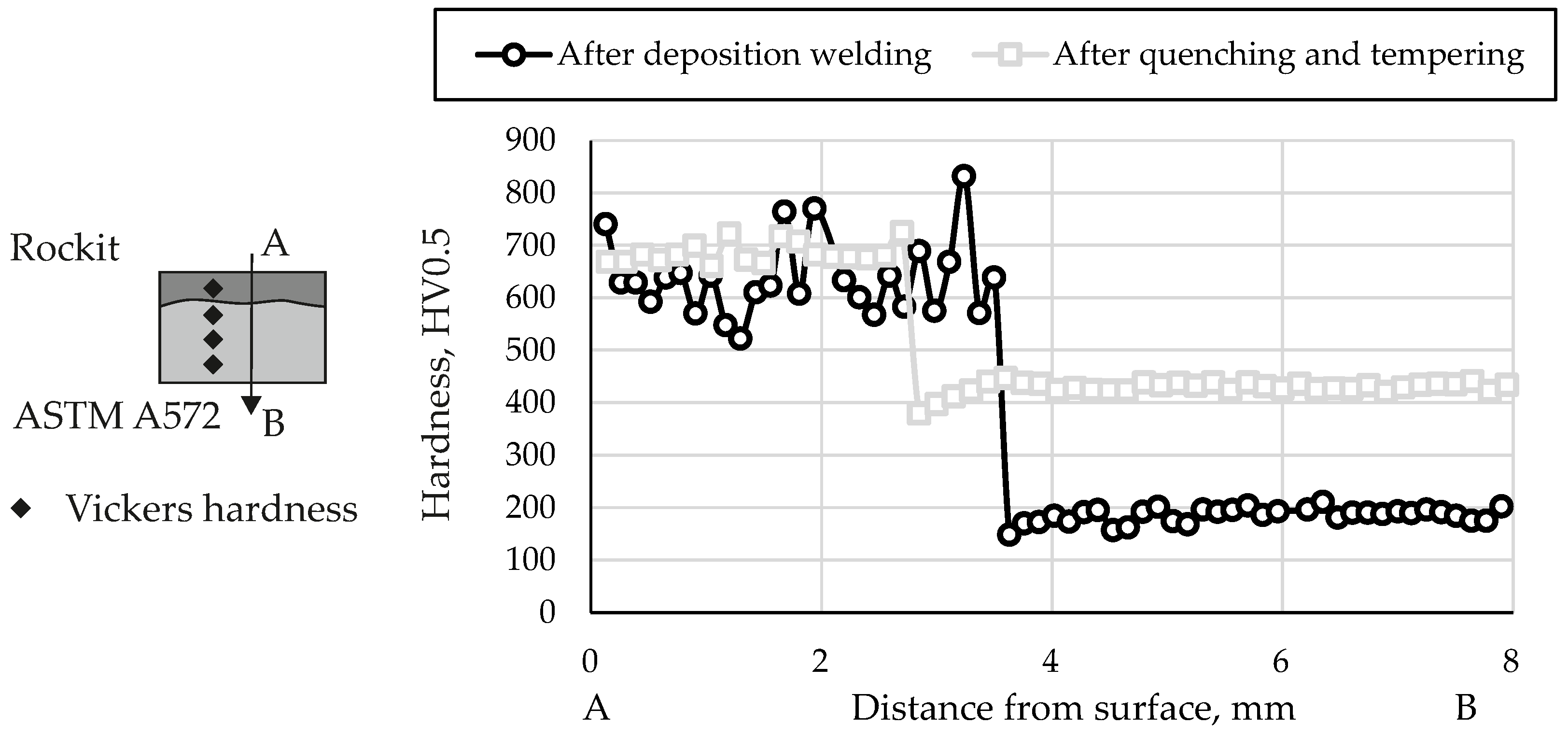
Figure 5 shows representative hardness profiles after welding and heat treatment. After PTA welding, the disk was machined, so that the thickness of the weld layer was 3.5 mm and the base material 6.5 mm. The final dimension after heat treatment and machining was 2.5 mm for the cladding layer and 5 mm for the base material. The layer height was verified by cross sections, see Figure 5. The hardness values in the cladding layer are in the range of 500–900 HV0.5. After welding, the highest hardness values, but also the highest variations, can be determined. The heat treatment homogenises the hardness further leading to a reduction of the scatter in hardness. The hardness values are in the range of 650–750 HV0.5. Additionally, the heat treatment increases the hardness from 200 HV0.5 to 400 HV0.5 in the base material.
In Figure 6, nano-hardness measurements are presented to further characterize the dilution zone. In addition, the position of the measuring field is presented on the specimen. The position was selected so that in the dilution zone was in the middle of the measuring field. The dash dot line in Figure 6 indicates the boundary of the dilution zone to the cladding layer or substrate. The nanohardness is specified in GPa. On the substrate, a mean hardness of about 3.25 GPa was measured. The distribution of the hardness in the substrate was homogenous. Some grains could be observed indicating a slight increase in hardness. In the Rockit section of the measuring field, a heterogeneous of the hardness was visible. In peak ranges, a hardness of about 18 GPa was achieved. The structure of these regions is identical to the former austenite grain boundaries of the cladding material. The peak ranges result due to the fact that in chromium-containing steels with carbon content, the carbide Cr 23 C 6 is preferentially formed at these former austenite grain boundaries [44]. The dilution zone is located between the dash dotted lines in Figure 6. There are no hard grain boundaries in the dilution zone. Here, a mean hardness of about 7 GPa was observed. The data of the hardness mapping shows that no hard or brittle layer forms in the dilution zone.

3.1.2. Manufacturing Induced Residual Stresses

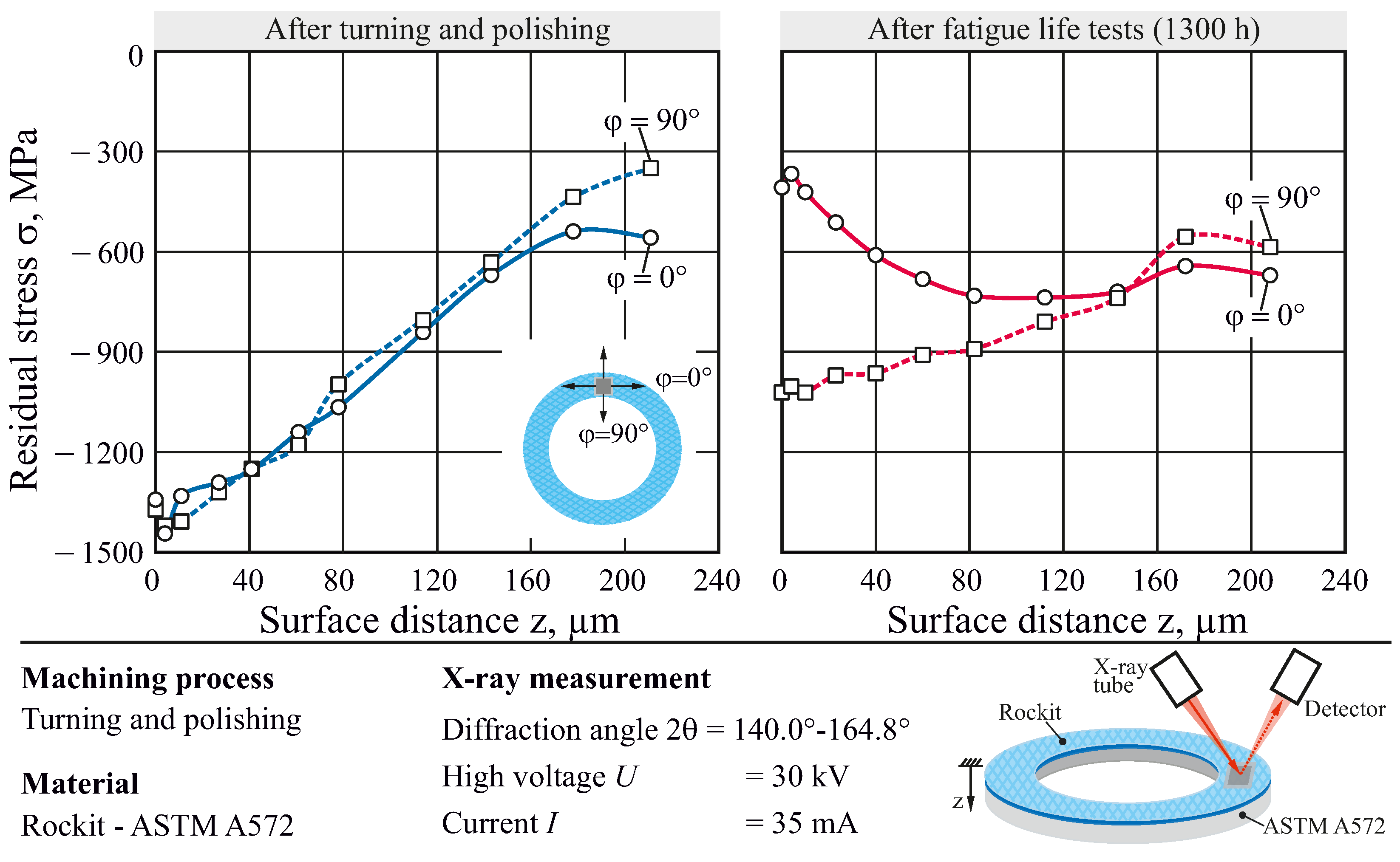
The results of residual stress depth profiles of the hybrid bearing washers are shown in Figure 7. Here, measurements were made in the circumferential direction ( φ = 0°) and in the radial direction ( φ = 90°). After the finishing process step of the hybrid bearing washers, maximum compressive residual stresses can be seen near the surface, which decrease with increasing distance from the surface. The residual stress depth profiles in the circumferential direction and in the radial direction follow the same course. The appearance of compressive residual stresses indicates high mechanical loading during machining. After employing the bearing washers in fatigue tests, a reduction of the compressive residual stresses directly below the surface can be seen. The compressive residual stresses in circumferential direction are reduced more significantly than in the radial direction. This is attributed to higher stresses during the rolling fatigue tests in circumferential direction.

3.1.3. Corrosion Properties

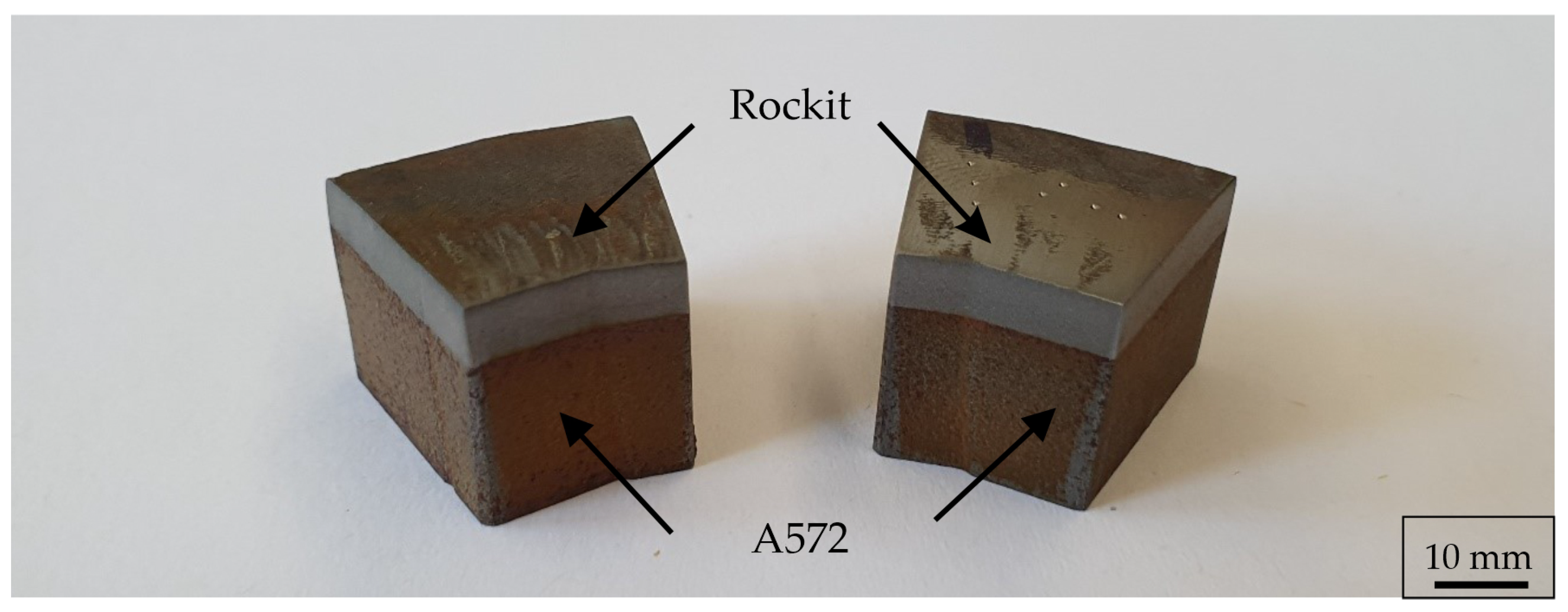
Salt spray tests were carried out on pre-production specimens to verify the corrosion resistance of the modified cladding material mixture as required during material selection. The samples were placed in a salt spray testing chamber SC/KWT 450 (Weiss Umwelttechnik, Reiskirchen, Germany). During the test, the specimens were continuously sprayed with a 5% saline solution with a controlled pH value of 6.8 at a temperature of 35 °C for 80 h. The testing was carried out in accordance to the international standard ISO 9227 [45]. In Figure 8, the samples are shown after testing. It can be seen that the Rockit® has just flash rust on the surface, while the base material is clearly corroded.

3.1.4. Non-Destructive Testing by Scanning Acoustic Microscopy (SAM)

SAM was used to analyse the bearing washers non-destructively prior to the fatigue tests in order to evaluate the quality of the manufacturing process. The SAM images in Figure 9 were taken at a depth of 0.5 mm below the surface. Bright features in the image indicate a possible change in Young’s modulus that occur when the acoustic signal reflects off material changes to the transducer. A slight noise of the measurement signal is superimposed on this. This leads to white spots in the displayed image when post-processing is carried out. Figure 9 shows an overview of the semi-finished parts after different process steps. In Figure 9a, a disc from the first batch is depicted with a systematic welding defect at the overlap from starting/ending of the weld seam, resulting in a local pore agglomeration and formation of cracks. Figure 9b shows the same washer after 200 h of testing (under the test conditions described in Section 3.2). The cracks caused by the welding process propagate under the cyclic load in the test and lead to failure through pitting. In Figure 9c, a washer from the second batch was scanned after 2500 h of fatigue life testing. No subsurface damage or cracks can be seen. The test was terminated because of damage on the counter washer.

3.2. Bearing Fatigue Life

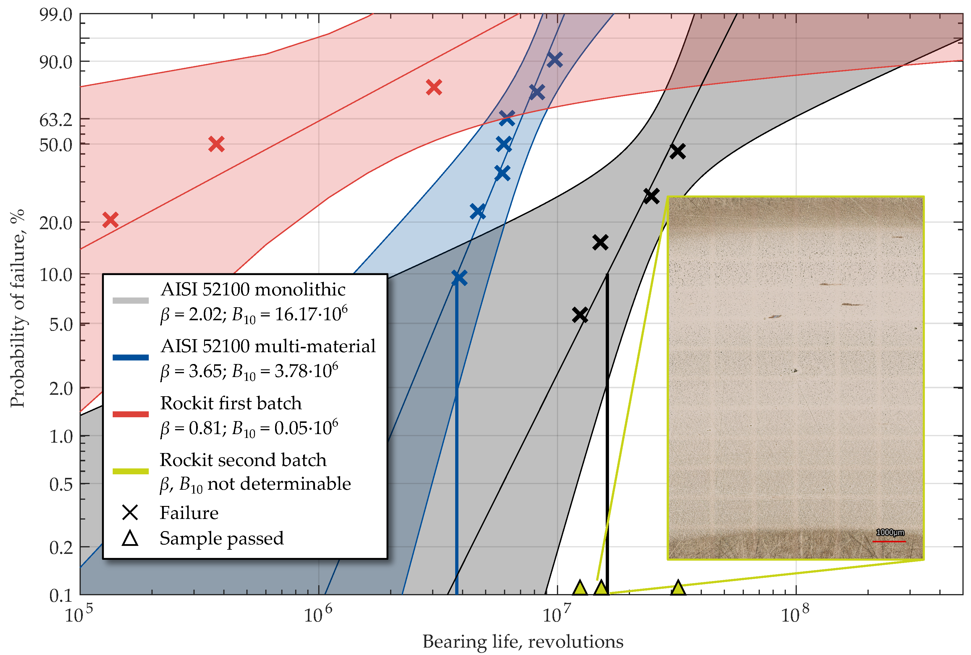
It could be shown by SAM measurements that bearing races manufactured from Rockit® show high potential due to low probability of defects, if the welding process is optimized (second batch). Furthermore, Rockit® cladding showed advantageous microstructural and residual stress properties. In order to investigate the rolling contact fatigue (RCF) performance, fatigue tests on a FE8 test rig were carried out. The results in the form of Weibull plots for Tailored Forming cylindrical roller thrust bearings are presented in Figure 10. For each set, the Weibull shape parameter β , which provides the slope of the regression line, is given with the B10 fatigue life in the legend. B10 refers to the bearing life with a 10% probability of a given sample population to fail. The confidence band is shown as a semi-opaque background for each individual set. As described earlier, two sets with Rockit® cladding were tested:
1
A first batch (Figure 10 red) with subsurface welding defects in the raceway region, as described in Section 3.1.4, was tested. This set showed a very low fatigue life of B10 = 0.05×10⁶ revolutions. The slope of β = 0.81 <1 suggests early failures. This could be correlated with the pores introduced by welding, c.f. Figure 9a,b. Ultimately, this led to the formation of fatigue cracks and the growth of these cracks to the surface, where chipping started, which triggered the shutdown criterion of the test rig.
2
In the second batch, these unavoidable welding defects were outside of the finished component, and thus had no effect on the fatigue life. With this set of three washers (Figure 10 green), no fatigue failure with the formation of pittings could be observed. The longest test of monolithic AISI 52100 ran more than 50×106 revolutions until failure. The Rockit® disc in the same test did not fail up to this point. The test was ended due to the failure of the other AISI 52100 washers used in the test rig. Another new set of counter-disks made of AISI 52100 was used to continue the test and eventually provoke damage to the Rockit® disk. However, this did not occur even after a total of approximately 75×106 revolutions (2500 h), until which the test was cancelled. This extended test was not included in the evaluation, since only up to the failure of the AISI 52100 disc at approximately 50×106 revolutions, it can be ensured that the Rockit® disc did not suffer secondary damage. The relevant parameters for the evaluation of β and B10 could not be determined due to the absence of failure of Rockit® washers.
The micrograph in the lower right of Figure 10 shows the surface of a Rockit® washer after testing. The sample was extracted approximately after B10 of the conventional bearing washers. It can be seen that a running track was created on the bearing washer as a result of the tribological load. However, this is classified as non-critical. Secondary damage occurred as a result of overrolling of hard particles from the surface chipping of the conventional counterface. This damage prevented further use of the bearing washers in the test, as a clear demarcation of surface and subsurface induced damage would not be possible.
During testing of the second Rockit® batch, the counter parts from commercially available bearing washers made from monolithic AISI 52100 failed due to fatigue. These bearings were used as a reference set of the current industry standard for bearing materials (Figure 10 grey). It is worth noting that the failures occurred on the shaft located washer as well as the fully conventional supporting bearing. Because of the test setup with three conventional and one hybrid bearing washer per test, the maximum likelihood method was used for the failed conventional washers. Two of the three conventional bearing washers were taken to represent a censored sample set.
A fatigue life of B10 = 16.17 × 10⁶ revolutions was thus determined for the conventional AISI 52100 monolithic washers. The Weibull slope of β = 2 is slightly increased from the expected value for RCF, although this is not unusual for FE8 tests due to low lubricant film thicknesses and increased slide to roll ratios at the ends of the rollers. All sets are compared with multi-material bearing washers with AISI 52100 cladding (Figure 10 blue) from earlier work [25]. It can be seen that the fatigue life of the AISI 52100 cladding of B10 = 3.78 × 10⁶ revolutions is lower then the AISI 52100 reference set. The total friction torque of the test head did not differ between AISI 52100 and Rockit® washers. Since both materials are based on steel and have comparable surface properties, this would not be expected either. The weighing of the specimens before and after the test for determination of possible weight loss, which is mandatory for FE8 testing, did not provide any information during the evaluation and was therefore not further considered.

4. Potential through Forming

Previous studies have shown that additional forming of the hybrid semi-finished products according to the tailored forming approach is advantageous for the subsequent application behaviour of bearing components with different materials [23,24,25]. Thermo-mechanical treatment results in a material-dependent recrystallization with grain refinement of the coarse weld microstructure. Therefore, in the following, it will also be investigated for Rockit® whether further optimization is possible through forming.

4.1. Uniaxial Compression Testing

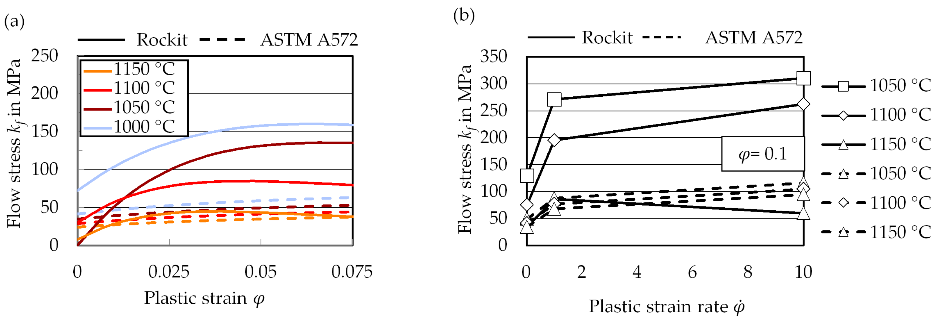
Uniaxial compression tests were carried out to investigate the flow behaviour of the Rockit® cladding. The aim was to identify the temperature range at which the flow properties are similar compared to the substrate. Cylindrical specimens with a diameter of 10 mm and a height of 15 mm were used. The specimens were prepared from welding tracks to investigate the material state after welding by wire eroding. The compression tests were carried out using the forming simulator Gleeble 3800-GTC (Dynamic Systems Inc., Poestenkill, NY, USA). The investigated temperatures ranged between 1000 °C and 1150 °C with steps of 50 °C. The specimens were heated conductively in an evacuated test chamber. Since the flow behaviour depends highly on the temperature and the strain rate, three different strain rates were also investigated. The examined strain rates φ ˙ were 0.01 s 1 , 1 s 1 and 10 s 1 . The specimens were upset to a plastic strain about φ = 0.3.
In Figure 11a, the flow curves at strain rate 0.01 s 1 within the temperature range of 1000 °C and 1150 °C are presented. Due to increasing temperature, the level of flow stress reduces significantly. However, the investigated steel shows reduced formability. No specimen reached a plastic strain of φ > 0.075. In addition, the flow curves of the substrate are shown in Figure 11a. The data of the substrate material, which clearly shows better forming properties, serves as a reference, and was taken from the simufact database. Compared to the cladding steel, the dependence on temperature is lower. The level of the flow stress is also significantly lower. However, at 1150 °C, the flow curves of the two steel grades nearly converge. The investigated Rockit® cladding also shows a great dependency on the strain rate. In Figure 11b, the flow stress is plotted as a function of the plastic strain rate. The flow stress was evaluated for every point at a plastic strain of φ = 0.075. The level of flow stress is again decreasing with increasing temperature. However, the level of flow stress increases with increasing plastic strain rate. At every investigated temperature, the level of flow stress increases very sharply when plastic strain rate increases from 0.01 s 1 to 1 s 1 . In comparison, the ASTM A572 substrate material is highly dependant on the strain rate.

4.2. Forging

Despite the limited formability, determined in the uniaxial compression tests, the potential of enhancing the overall mechanical properties of the bearing through forming on a global scale was tested in an upsetting process. The upsetting process was carried out on an automated screw press SPR 500 (Lasco Umformtechnik GmbH, Coburg, Germany) at a temperature maximum of 1150 °C reached through induction heating. After forming, the specimens show delamination between the cladding layer and the base as well as macroscopic and microscopic fractures in the cladding surface due to limited formability. Figure 12 shows the influence of forming on the semi-finished part with Rockit® cladding as SAM image. The limited formability causes cracking in the cladding layer around the entire circumference, as shown in Figure 12b at a depth of 0.5 mm and below. Cracks from this batch can certainly lead to early failure in the fatigue life tests, as observed with the first batch in Figure 9. While the base material is upset and spread, the cladding layer shows no significant deformation. The results of the forging tests on a global scale are therefore consistent with the uniaxial compression tests on a smaller scale. The applied material is therefore insufficient for forming and enhancing the properties in the cladding layer. The developed material requires further modification in order to reach formability, to enhance the material properties through forging, utilising the tailored forming approach.

5. Discussion

When analysing the worn surfaces, it was noticed that the Rockit® washers already showed signs of surface distress after a running time of approximately 500 h. This was not observed even with the conventional bearing washers that failed due to fatigue after twice the running time. However, from the results presented here, a higher fatigue life can be expected. Due to the small number of specimens and very long experimental run times without failures, this cannot be quantified. The reasons for the enhanced fatigue behaviour must be related to the material itself:
  • Due to the carbide forming elements such as chrome and vanadium and the dentritic structure, hardness values are achieved that meet the requirements of rolling bearing steel. Due to the different cooling rates that occur during the welding process, scattering hardness values in the range of 500–900 HV0.5 (approx. 49–67 HRC) after welding occur. This results from the martensitic structure, which is formed by cooling in static air after welding. The heat treatment leads to a homogenization of the microstructure and a largely homogeneous hardness in the cladding material, as shown in Figure 5. Microstructural changes are visible in the micrographs after heat treatment, see Figure 3. The martensitic areas appear darker and carbides are recognisable under high magnification. During austenitization, a fraction of the chromium and vanadium carbides were dissolved. The carbon which forms these carbides was then available for supersaturating the martensite during quenching, contributing to a higher martensite hardness.
  • The high hardness and strength of the cladding material is attributed to the high quantity of carbides, which are distributed throughout the cladding microstructure. However, since hardness alone does not determine the bearing performance and remains below that of AISI 52100, the present microstructure of mixed Rockit® obviously exhibits high fatigue strength. The fine-grained and homogeneously distributed microstructure is beneficial to fatigue strength. The decisive factor for the high strength in the rolling bearing test of the second batch is the largely defect-free weld. Neither pores nor inclusions or cracks could be detected in the micrographs (Figure 3) or ultrasonic microscopic images (Figure 9).
  • The nano-hardness values vary significantly due to the locally distributed carbides, see Figure 6. These are localized after deposition welding on the former austenite grain boundaries of a cladding and have a higher hardness than the martensite. Further investigations must be carried out with regard to the local distribution of the elements due to the probability that in the grain boundaries the carbide Cr 23 C 6 occurs. As a direct result of these carbide precipitations, the chromium content nearby the grain boundaries can decrease, which increases the risk of intercirstalline corrosion.
  • Compared to the previously studied hybrid AISI 52100—AISI 1022M bearing washers, the hybrid Rockit®—ASTM A572 bearing washers are characterized with significantly higher compressive residual stresses over a large depth range. Accordingly, this is also a influencing factor, which leads to a possible increase in fatigue life.
  • In addition to their hardness, which is beneficial for working conditions of the resulting component, the carbides are also highly temperature stable. This results in low deformibility even at high temperatures. The uniaxial compression tests as well as the forging tests confirmed this behaviour. The cladding layer could not be formed in the upsetting process despite measures like a locally adjusted temperature gradient. The potential for enhancing the application properties through forming can therefore be considered as low for this material combination.

6. Conclusions

Highly fatigue-resistant rolling bearing raceways were additively manufactured by means of plasma-transferred arc welding. For this purpose, a new material system consisting of modified Rockit® (0.52 wt.% C, 0.9% Si, 14% Cr, 0.4% Mo, 1.8% Ni, 1.2% V, bal. Fe) as cladding material on ASTM A572 as substrate was developed. With subsequent heat treatment and machining, bearing washers for a cylindrical roller thrust bearing of type 81,212 were produced. The initial welding process showed optimizing potential due to induced pores, which lead to early bearing failures during tribological testing. After further process optimization, nearly defect-free welding of the Rockit® cladding material was possible. The newly developed hybrid material and processing strategy showed good performance in tribological fatigue life tests on a rolling bearing test bench, exceeding the fatigue life of conventional bearing washers made of monolithic AISI 52100. The reasons for this were:
1
Absence of defects;
2
Finely distributed martensitic microstructure with very hard vanadium and chromium precipitations at the grain boundaries;
3
Homogeneous hardness profile of 700 HV after heat treatment;
4
Compressive residual stresses with a peak magnitude of approximately 1000 MPa up to a depth of 200 µm, which do not relieve during operation.
Rockit® also has the advantage of being highly resistant to corrosion. Following the Tailored Forming process chain, further improvement of material properties through forming was assessed. This modification of the manufacturing route provided no potential for Rockit® as a cladding material. Due to high flow stresses, no significant deformation was achieved in the cladding layer despite inhomogeneous heating to 1150 °C.
In summary, a modified Rockit® cladding shows better tribological performance regarding rolling contact fatigue than the current standard. The softer base material would have failed early without a cladding layer due to lower fatigue strength or plastic deformation during the application of the tribological load. Thus, the performance of the tribosystem could be enhanced by using additively manufactured bearings with customized cladding material.
The quantification of fatigue life improvement was not possible in this study because no Rockit® bearing washer failed. For future research, tests with four Rockit® washers and ceramic rolling elements will therefore be carried out. In addition, the possibility of an adapted heat treatment strategy including soft annealing is investigated in order to improve the work-hardening capacity of the material. It is also planned to utilize the good properties of the cladding material for other components subjected to tribological loading with more complex geometries, such as radial bearings or gears. However, as this study has also shown, the success of the technology depends on a high quality of the components, and thus on high process reliability, but offers great potential.

Author Contributions

Conceptualization, methodology, investigation, visualization, and writing—original draft preparation, F.S., M.Y.F., C.B., C.K., J.P., V.P. and T.C.; supervision as well as writing—review, F.P., T.H., S.H., F.N., B.B., J.U., H.W., B.D., B.-A.B., H.J.M. and G.P.; project administration, T.H., J.U., B.D., B.-A.B., H.J.M. and G.P. All authors have read and agreed to the published version of the manuscript.

Funding

This research was funded by the German Research Foundation (Deutsche Forschungsgemeinschaft, DFG) under grant number 252662854.

Institutional Review Board Statement

Not applicable.

Informed Consent Statement

Not applicable.

Data Availability Statement

The data that support the findings of this study are available from the corresponding author upon request.

Acknowledgments

We would like to thank Senad Dizdar, Högänäs AB, for providing us with a first sample of the two Rockit® powders used. The rest of the material required for manufacturing was purchased. The results presented in this paper were obtained within the Collaborative Research Centre 1153 “Process chain to produce hybrid high performance components by Tailored Forming” in the subprojects A2, A4, B2, B4, C1, C3, and T1. The authors thank the German Research Foundation (DFG) for their financial support of this project. The publication of this article was funded by the Open Access Fund of the Leibniz Universität Hannover.

Conflicts of Interest

The authors declare no conflict of interest. The funders had no role in the design of the study; in the collection, analyses, or interpretation of data; in the writing of the manuscript, or in the decision to publish the results.

References

  1. Lai, J.; Lund, T.; Rydén, K.; Gabelli, A.; Strandell, I. The Fatigue Limit of Bearing Steels – Part I: A Pragmatic Approach to Predict Very High Cycle Fatigue Strength. Int. J. Fatigue 2011, 38, 155–168. [Google Scholar] [CrossRef]
  2. Gabelli, A.; Lai, J.; Lund, T.; Rydén, K.; Strandell, I.; Morales-Espejel, G.E. The fatigue limit of bearing steels—Part II: Characterization for life rating standards. Int. J. Fatigue 2012, 38, 169–180. [Google Scholar] [CrossRef]
  3. Vencl, A.; Gasic, V.; Stojanović, B. Fault tree analysis of most common rolling bearing tribological failures. IOP Conf. Ser. Mater. Sci. Eng. 2017, 174. [Google Scholar] [CrossRef]
  4. Squired, H.; Radcliffe, S. A comparison of the performance of AISI 52100 and AISI 440C ball bearings in a corrosive environment. J. Mater. Sci. 1983, 18, 3611–3620. [Google Scholar] [CrossRef]
  5. Tonicello, E.; Girodin, D.; Sidoroff, C.; Fazekas, A.; Perez, M. Rolling Bearing Applications: Some Trends in Materials and Heat Treatments. Mater. Sci. Technol. 2012, 28, 5. [Google Scholar] [CrossRef]
  6. Wrobel, R.; Mecrow, B. Additive Manufacturing in Construction of Electrical Machines—A Review. In Proceedings of the 2019 IEEE Workshop on Electrical Machines Design, Control and Diagnosis (WEMDCD), Athens, Greece, 22–23 April 2019; pp. 15–22. [Google Scholar] [CrossRef] [Green Version]
  7. Hölker, R.; Haase, M.; Khalifa, N.B.; Tekkaya, A.E. Hot Extrusion Dies with Conformal Cooling Channels Produced by Additive Manufacturing. Mater. Today: Proc. 2015, 2, 4838–4846. [Google Scholar] [CrossRef]
  8. Wang, J.; Dommati, H.; Hsieh, S. Review of additive manufacturing methods for high-performance ceramic materials. Int. J. Adv. Manuf. Technol. 2019, 103, 2627–2647. [Google Scholar] [CrossRef]
  9. Ziółkowski, M.; Dyl, T. Possible Applications of Additive Manufacturing Technologies in Shipbuilding: A Review. Machines 2020, 8, 84. [Google Scholar] [CrossRef]
  10. Andrearczyk, A.; Bagiński, P. The Use of Additive Manufacturing Technology to Manufacture Slide Bearing Sleeves—A Preliminary Study. Tribologia 2020, 3, 7–14. [Google Scholar] [CrossRef]
  11. Hetzner, D. Laser Glazed Bearings. In Bearing Steels: Into the 21st Century; Hoo, J., Green, W., Eds.; ASTM International: West Conshohocken, PA, USA, 1998; pp. 471–495. [Google Scholar] [CrossRef]
  12. Ringsberg, J.W.; Skyttebol, A.; Josefson, B.L. Investigation of the Rolling Contact Fatigue Resistance of Laser Cladded Twin-Disc Specimens: FE Simulation of Laser Cladding, Grinding and a Twin-Disc Test. Int. J. Fatigue 2005, 27, 702–714. [Google Scholar] [CrossRef]
  13. Yue, T.M.; Huang, K.J.; Man, H.C. In Situ Laser Cladding of Al 2 O 3 Bearing Coatings on Aluminium Alloy 7075 for Improvement of Wear Resistance. Surf. Eng. 2007, 23, 142–146. [Google Scholar] [CrossRef]
  14. Weisheit, A.; Gasser, A.; Backes, G.; Jambor, T.; Pirch, N.; Wissenbach, K. Direct Laser Cladding, Current Status and Future Scope of Application. In Laser-Assisted Fabrication of Materials; Majumdar, J.D., Manna, I., Eds.; Springer: Berlin/Heidelberg, Germany, 2013; Volume 161, pp. 221–240. [Google Scholar] [CrossRef]
  15. Kotkowiak, M.; Piasecki, A.; Kulka, M. Laser Alloying of Bearing Steel with Boron and Self-Lubricating Addition. Arch. Mech. Technol. Mater. 2016, 36, 7–11. [Google Scholar] [CrossRef] [Green Version]
  16. Mahade, S.; Awe, S.A.; Björklund, S.; Lukáč, F.; Mušálek, R.; Joshi, S. Sliding Wear Behavior of a Sustainable Fe-based Coating and Its Damage Mechanisms. Wear 2022, 500–501, 204375. [Google Scholar] [CrossRef]
  17. Sexton, L. Laser Cladding: Repairing and Manufacturing Metal Parts and Tools. In OPTO Ireland; Glynn, T.J., Ed.; SPIE: Bellingham, WA, USA, 2003; p. 462. [Google Scholar] [CrossRef]
  18. Torims, T. The Application of Laser Cladding to Mechanical Component Repair, Renovation and Regeneration. In DAAAM International Scientific Book, 1st ed.; Katalinic, B., Tekic, Z., Eds.; DAAAM International: Vienna, Austria, 2013; Volume 12, pp. 587–608. [Google Scholar] [CrossRef]
  19. Molina, C.; Araujo, A.; Bell, K.; Mendez, P.F.; Chapetti, M. Fatigue Life of Laser Additive Manufacturing Repaired Steel Component. Eng. Fract. Mech. 2021, 241, 107417. [Google Scholar] [CrossRef]
  20. Tate, J.G.; Richardson, B.S.; Love, L.J. Additive Manufacturing for Low Volume Bearings. Technical Report ORNL/TM-2017/451, 1410926, 2017. Available online: https://www.ornl.gov/sites/default/files/2019-06/web_Schaeffler_MDF-TC-2016.pdf (accessed on 25 September 2022). [CrossRef]
  21. Mirring, P.; Rottmann, A.; Merklein, C. Selective Laser Melting (SLM) of M50NiL—Enabling Increased Degrees of Freedom in New Design Concepts. In Bearing Steel Technologies: 12th Volume, Progress in Bearing Steel Metallurgical Testing and Quality Assurance; ASTM International: West Conshohocken, PA, USA, 2020. [Google Scholar] [CrossRef]
  22. Behrens, B.A.; Overmeyer, L.; Barroi, A.; Frischkorn, C.; Hermsdorf, J.; Kaierle, S.; Stonis, M.; Huskic, A. Basic Study on the Process Combination of Deposition Welding and Subsequent Hot Bulk Forming. Prod. Eng. 2013, 7, 585–591. [Google Scholar] [CrossRef]
  23. Pape, F.; Coors, T.; Barroi, A.; Hermsdorf, J.; Mildebrath, M.; Hassel, T.; Kaierle, S.; Matthias, T.; Chugreev, A.; Chugreeva, A.; et al. Tribological Study on Tailored-Formed Axial Bearing Washers. Tribol. Online 2018, 13, 320–326. [Google Scholar] [CrossRef] [Green Version]
  24. Behrens, B.A.; Chugreev, A.; Matthias, T.; Poll, G.; Pape, F.; Coors, T.; Hassel, T.; Maier, H.J.; Mildebrath, M. Manufacturing and Evaluation of Multi-Material Axial-Bearing Washers by Tailored Forming. Metals 2019, 9, 232. [Google Scholar] [CrossRef] [Green Version]
  25. Coors, T.; Mildebrath, M.; Büdenbender, C.; Saure, F.; Faqiri, M.Y.; Kahra, C.; Prasanthan, V.; Chugreeva, A.; Matthias, T.; Budde, L.; et al. Investigations on Tailored Forming of AISI 52100 as Rolling Bearing Raceway. Metals 2020, 10, 1363. [Google Scholar] [CrossRef]
  26. Saifon, S.; Tharanon, U.A.; Karuna, T. Investigation of Single Layer and Bilayer of Plasma Transferred Arc (PTA) Coatings of Fe-Cr-V Powder. Key Eng. Mater. 2021, 902, 49–55. [Google Scholar] [CrossRef]
  27. Qi, X.; Jia, Z.; Yang, Q.; Yang, Y. Effects of vanadium additive on structure property and tribological performance of high chromium cast iron hardfacing metal. Surf. Coatings Technol. 2011, 205, 5510–5514. [Google Scholar] [CrossRef]
  28. Olofsson, U.; Lyu, Y.; Åström, A.H.; Wahlström, J.; Dizdar, S.; Nogueira, A.P.G.; Gialanella, S. Laser Cladding Treatment for Refurbishing Disc Brake Rotors: Environmental and Tribological Analysis. Tribol. Lett. 2021, 69, 57. [Google Scholar] [CrossRef]
  29. DIN EN 10088-3:2014-12; Nichtrostende Stähle_- Teil_3: Technische Lieferbedingungen für Halbzeug, Stäbe, Walzdraht, gezogenen Draht, Profile und Blankstahlerzeugnisse aus korrosionsbeständigen Stählen für allgemeine Verwendung; Deutsche Fassung EN_10088-3:2014. Beuth Verlag GmbH: Berlin, Germany, 2014. [CrossRef]
  30. Ertugrul, G.; Hälsig, A.; Kusch, M. High deposition additive manufacturing by tandem plasma transferred arc welding. J. Addit. Manuf. Technol. 2021, 1, 566. [Google Scholar] [CrossRef]
  31. Höganäs AB. Rockit® 401 - Sustainable Solution to Replace Hard Chrome Plating. 2021. Available online: https://www.hoganas.com/globalassets/download-media/sharepoint/brochures-and-datasheets—all-documents/rockit_rockit-401-sustainable-solution-to-replace_2275hog.pdf (accessed on 25 September 2022).
  32. Höganäs AB. Rockit® 606/706 – Combat Impact and Abrasive Wear. 2021. Available online: https://www.hoganas.com/globalassets/download-media/sharepoint/brochures-and-datasheets—all-documents/rockit_rockit-606-706_2653hog.pdf (accessed on 25 September 2022).
  33. DIN 51819-1; Testing of Lubricants—Mechanical-dynamic Testing in the Roller Bearing Test Apparatus FE8—Part 1: General Working Principles. Beuth Verlag GmbH: Berlin, Germany, 2016.
  34. VW PV 1483; (Factory Standard)—Gear Oils—Testing the Pitting Load Capacity in Rolling Bearings. Volkswagen AG: Wolfsburg, Germany, 2007.
  35. ISO/TS 16281; Rolling Bearings—Methods for Calculating the Modified Reference Rating Life for Universally Loaded Bearings. Beuth Verlag GmbH: Berlin, Germany, 2008.
  36. DIN EN ISO 6507-1; Metallic Materials—Vickers Hardness Test. Beuth Verlag GmbH: Berlin, Germany, 2018.
  37. Jomaa, W.; Songmene, V.; Bocher, P. An Investigation of Machined-Induced Residual Stresses and Microstructures of Induction-Hardened AISI 4340 Steel. Mater. Manuf. Process. 2016, 31, 838–844. [Google Scholar] [CrossRef]
  38. McCLUNG, R.C. A Literature Survey on the Stability and Significance of Residual Stresses during Fatigue. Fatigue Fract. Eng. Mater. Struct. 2007, 30, 173–205. [Google Scholar] [CrossRef]
  39. Guo, Y.; Warren, A.; Hashimoto, F. The Basic Relationships between Residual Stress, White Layer, and Fatigue Life of Hard Turned and Ground Surfaces in Rolling Contact. CIRP J. Manuf. Sci. Technol. 2010, 2, 129–134. [Google Scholar] [CrossRef]
  40. Moussaoui, K.; Mousseigne, M.; Senatore, J.; Chieragatti, R. The Effect of Roughness and Residual Stresses on Fatigue Life Time of an Alloy of Titanium. Int. J. Adv. Manuf. Technol. 2015, 78, 557–563. [Google Scholar] [CrossRef]
  41. Pramanik, A.; Dixit, A.R.; Chattopadhyaya, S.; Uddin, M.S.; Dong, Y.; Basak, A.K.; Littlefair, G. Fatigue Life of Machined Components. Adv. Manuf. 2017, 5, 59–76. [Google Scholar] [CrossRef] [Green Version]
  42. Guo, Y.B.; Warren, A.W. The basic relationship between machining induced residual stress profiles and Fatigue Life. ASME Int. Manuf. Sci. Eng. Conf. 2008, 2, 103–107. [Google Scholar] [CrossRef]
  43. Sun, C.; Xiu, S.; Xing, C.; Lu, H.; Wang, D.; Wang, R. Influence of prestress grinding hardening residual stress on rolling contact fatigue. Mater. Sci. Technol. 2022, 38, 716–729. [Google Scholar] [CrossRef]
  44. Sulzer Pumps. Chapter eight—Materials and Corrosion. In Centrifugal Pump Handbook, 3rd ed.; Sulzer Pumps, Ed.; Butterworth-Heinemann: Oxford, UK, 2010; pp. 227–250. [Google Scholar] [CrossRef]
  45. DIN EN ISO 9227:2017-07; Korrosionsprüfungen in küNstlichen Atmosphären_–Salzsprühnebelprüfungen (ISO_9227:2017); Deutsche Fassung EN_ISO_9227:2017. Beuth Verlag GmbH: Berlin, Germany, 2017. [CrossRef]
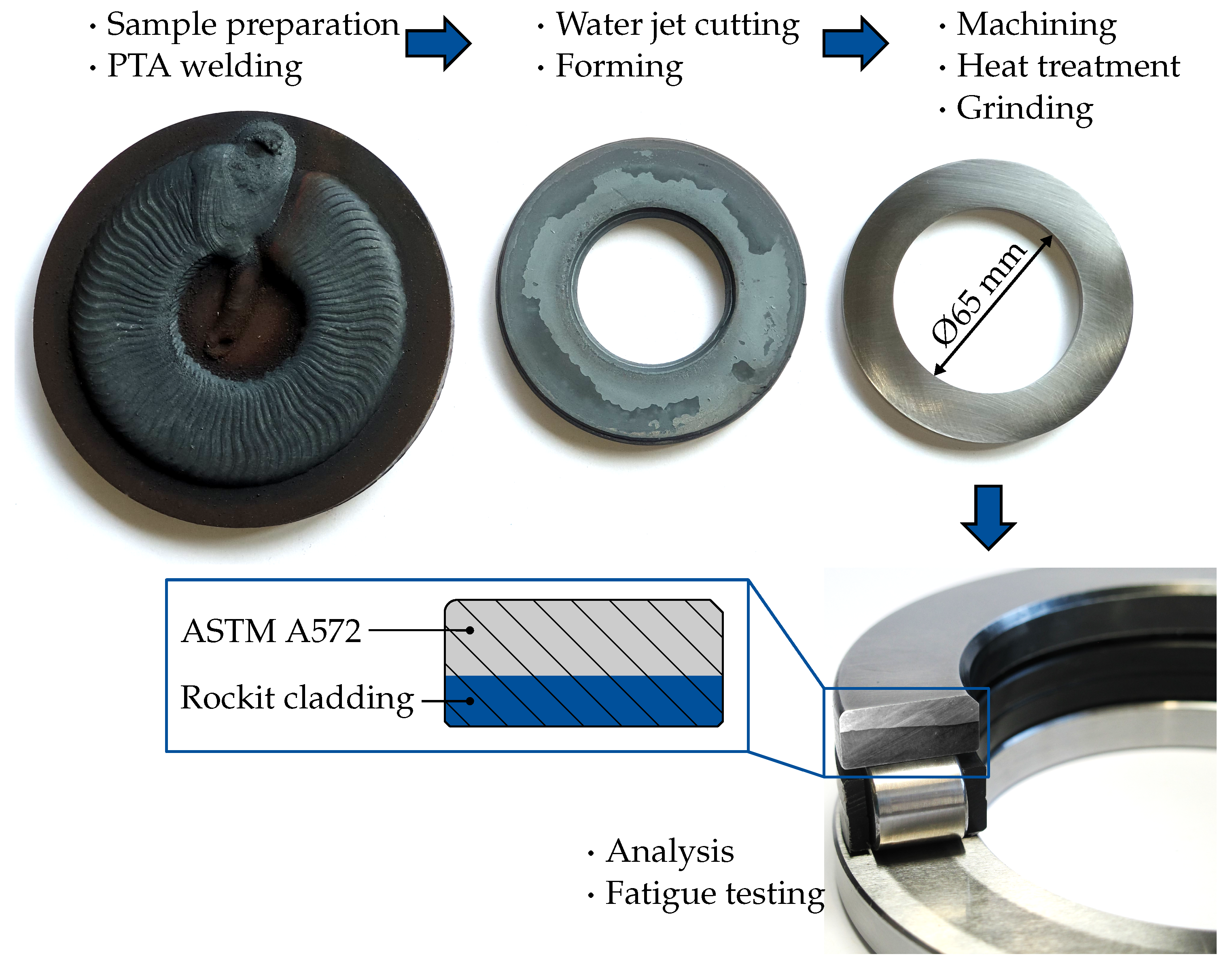
Figure 1. Workflow for Tailored Forming of bearing raceway.
Coatings 12 01699 g001
Figure 2. PTA-workstation.
Coatings 12 01699 g002
Figure 3. Micrographs of the transition zone: (a) after deposition welding; (b) after heat treatment (quenching and tempering); etched with 2% nitric acid solution + V2A acid solution.
Coatings 12 01699 g003
Figure 4. EDX mapping of the microstructure after PTA.
Coatings 12 01699 g004
Figure 5. Hardness profiles of the hybrid Rockit® bearing washers.
Coatings 12 01699 g005
Figure 6. Nano-hardness mapping (right) with position of the measuring field (left) on the hybrid Rockit®—ASTM A572 sample.
Coatings 12 01699 g006
Figure 7. Residual stress depth profiles after machining (left) and after fatigue life tests (right).
Coatings 12 01699 g007
Figure 8. Specimens after corrosion testing.
Coatings 12 01699 g008
Figure 9. SAM measurments of semi finished parts: (a) first batch after welding and machining, (b) first batch after welding, machining and 200 h in the test rig and (c) second batch after fatigue life test with no failure.
Coatings 12 01699 g009
Figure 10. Weibull plot of Tailored Forming bearing washers.
Coatings 12 01699 g010
Figure 11. Flow curves of the coating material (Rockit®) and the substrate material (ASTM A572) (a), influence of the strain rate at φ = 0.075 on the flow stress at different test temperatures (b).
Coatings 12 01699 g011
Figure 12. SAM measurments of semi-finished parts: (a) washer after welding and machining, (b) washer after welding and forming.
Coatings 12 01699 g012
Table 1. Chemical composition of cladding and base material in wt.% ± 0.005; N < 0.05; P & S < 0.01.
MaterialCSiMnCrNiCuVFe
ASTM A5720.20.51.6--0.55-bal.
Rockit® 4010.15--18.392.4--bal.
Rockit® 7062.61.1-4.95.1-6.1bal.
Rockit® cladding0.540.24-15.731.92-1.22bal.
Table 2. Welding parameters.
ParameterValue
Current180–220 A
Voltage25–27 V
Welding speed (table)72°/min
Welding speed (torch)0.1 m/min
Oscillation frequency1 Hz
Amplitude3 mm
Transport gas flow (Argon)1.5 l/min
Plasma gas flow (Argon)1.3–1.6 l/min
Shielding gas flow (Argon)13 l/min
Particle size60–153 µm
Deposition rate12 kg/h
Table 3. Parameters for fatigue testing.
Loadstep1: Approval Testing2: Accelerated Life Tests
Rotational speed n 1 500 rpm for 24 h500 rpm until failure
Rotational speed n 2 750 rpm for 226 h-
Axial load F a x 60 kN80 kN
Number of rolling elements1915
Hertzian pressure p m a x 1.8 GPa2.2 GPa
Load ratio C / P 2.281.35
Max. bearing temperature T≤86 °C<99 °C
Viscosity ratio κ 0.640.46
Fatigue life L n m r 38.1 × 10 6 1.8 × 10 6
Fatigue life L h m r 864 h60.3 h
Publisher’s Note: MDPI stays neutral with regard to jurisdictional claims in published maps and institutional affiliations.