Article

Laser Polishing and Annealing Injection Mold Using Dual-Beam Laser System

1
School of Intelligent Manufacturing and Equipment, Shenzhen Institute of Information Technology, Shenzhen 518172, China
2
School of Mechanical Engineering, Guangxi University, Nanning 530004, China
3
School of Foreign Languages, Shenzhen Institute of Information Technology, Shenzhen 518172, China
*
Author to whom correspondence should be addressed.
Coatings 2022, 12(12), 1822; https://doi.org/10.3390/coatings12121822
Submission received: 27 October 2022 / Revised: 20 November 2022 / Accepted: 21 November 2022 / Published: 25 November 2022
(This article belongs to the Special Issue Laser Surface Treatments and Additive Manufacturing)

Abstract

:
One of the challenges regarding the application of laser polishing in injection mold manufacturing is to eliminate the tensile residual stress on a polished cavity surface without the extra expenses of an annealing vacuum furnace. This study aims to develop a fast laser annealing method using a dual-beam laser system by which a mold cavity can be laser-polished and then laser-annealed. Fourteen mold steel specimens were laser-polished by a dual-beam laser, resulting in a roughness reduction from the initial state, Sa 1.11 μm, to Sa 0.16 μm, a smoother surface finish. A numerical simulation of laser annealing using the current CW laser was implemented to optimize the laser annealing parameters to guide the experiment of CW laser annealing. XRD measurement results showed that the tensile residual stress dropped from an initial 638 MPa to 10 MPa in an annealing cycle time of 40 min at 750 °C; therefore, fatigue cracks or stress corrosion cracks (SCC) on the mold cavity will no longer occur. Confocal microscopy, X-ray diffraction, and scanning electron microscopy were used to obtain the microstructure and phase composition of the microstructures, demonstrate that laser polishing and laser annealing by a dual-beam laser is a fast and effortless technique which can be effectively employed in injection mold manufacturing.

1. Introduction

One of the new approaches to automatic machining of metal parts is to rapidly polish their surfaces by means of laser radiation. In recent years, laser polishing has been more widely applied due to the ability to quickly and efficiently polish surfaces [1]. Most injection mold cavities are currently polished by conventional technologies, such as mechanical polishing, chemical polishing, or ultrasonic polishing, etc. [2,3,4], and a few mold makers are reviewing the plan of the replacement of conventional polishing with laser polishing.
Laser polishing has potential advantages in replacing traditional polishing technology due to its high-speed and smooth polished surface [5,6,7,8]. Zhou et al. [8] developed a dual-beam laser system to polish the injection tool steel S136H and showed that a rough cavity surface was rapidly polished from the initial state Ra 0.86 µm to Ra 0.15 µm, and the polishing efficiency was as high as 2s890 cm2/H. Temmler et al. [9] investigated the influence of multi-step laser polishing on the microstructural properties of the remelted surface layer of tool steel H11, and a minimal surface roughness of Ra 0.05 µm was achieved in an argon process atmosphere with an additional 6 vol% of CO2.
In the laser polishing process, the laser melts a thin surface layer to form a dynamic melted pool, in which melted material flows from the peaks to the valleys due to the surface tension, to evenly distribute the recently melted material across the surface; thus, creating a much smoother surface finish [10]. Tensile residual stresses are developed when the heating in the dynamic molten pool is too high or the cooling rate is too fast, an inescapable consequence of laser polishing processes, with magnitudes that are often a high proportion of the yield or proof strength. High tensile residual stresses of up to 926 MPa can be introduced by laser polishing [9].
Tensile residual stresses substantially accelerate crack propagation in an injection mold cavity if the cavity surface is polished by a laser. Tensile residual stress often induces both fatigue crack initiation and environmentally assisted cracking, resulting in crucial damage. Figure 1a shows a laser-polished mold cavity made of 718H steel. After its 100,000 shots, a long crack was found on the cavity surface, as shown in Figure 1b, and thus the investigation of preventive measures of cracking due to tensile residual stress is very important for injection mold cavities polished by laser processes.
Paris et al. [11] first proposed that the relationship between fatigue crack growth rates per cycle ( d α / d N ) and the stress intensity range ( Δ K ) could be described by:
d α d N = C ( Δ K ) n
where α is the crack size, N is the molding number, and C is a constant of the tool steel. According to Formula (1), in the initial crack stage, the ( d α / d N ) value is large, the crack easily grows, and the growth speed is fast. With the progress of fatigue work, the value of ( d α / d N ) decreases successively, and approaches to zero. When ( d α / d N ) = 0, the crack expands to the maximum. This state is unfavorable to the whole part and ultimately leads to the failure of the part.
The value of ∆K was calculated from the formula proposed by Novikov et al. [12]:
Δ K = Δ σ ( π a ) 1 / 2 2 b π a tan π a 2 b 1 / 2 1 1 8 ( σ m σ T ) 2 1 / 2
where a is half the length of the fatigue crack, 2b is the total width of the sample, σ m is the yield strength of the tool steel, and σ T is the mean tensile residual stress of the cycle.
Δ σ = σ m σ T
Environmentally assisted cracking is mainly related to stress corrosion crack (SCC). Russell H. Jones [13] described that the observed crack propagation is the result of the combined and synergistic interaction of mechanical stress and corrosion reactions. The stresses required to cause SCC are small, usually below the macroscopic yield stress, and are tensile in nature. The stresses can be externally applied, but tensile residual stresses often cause SCC failures. Injection molds polished by lasers often suffer from tensile residual stresses and chemical corrosion, since a variety of resins, which are molded in the mold cavity at high temperatures, do not possess outstanding corrosion-resistant properties. In metallic alloys susceptible to this form of cracking, it has been hypothesized that a high-speed crack is nucleated within the nanoporous structure that penetrates the undealloyed parent phase material for distances of order microns [14,15,16]. Many cases of injection mold damage have been found in China due to SCC [17], verifying this conclusion in practice.
Tensile residual stress-relief annealing can improve the performance of the laser-polished injection mold cavity, but an expensive annealing vacuum furnace is needed. However, so far, a low-cost processing method to eliminate the tensile residual stress on the laser-polished mold cavity has rarely been introduced. In the 3rd–5th Conference on Laser Polishing, LaP 2018–2022 (held in Fraunhofer ILT, Aachen, Germany), besides traditional vacuum furnace annealing, no other innovation method of tensile residual stress-relief annealing was reported pertaining to laser polishing of both tool steel and additively manufactured alloys. In the last five years, many scholars have engaged in laser polishing research [9,18,19,20,21,22,23,24,25], but none have presented an innovative method of eliminating tensile residual stress.
To save costs in mold manufacturing processes, mold makers use the original laser resources to remove tensile residual stress without the extra expenses of an annealing vacuum furnace. This study aims to fill the gap between the expectations of many mold makers and the current methodology of tensile residual stress-relief annealing by means of an innovative approach to laser annealing.

2. Materials and Methods

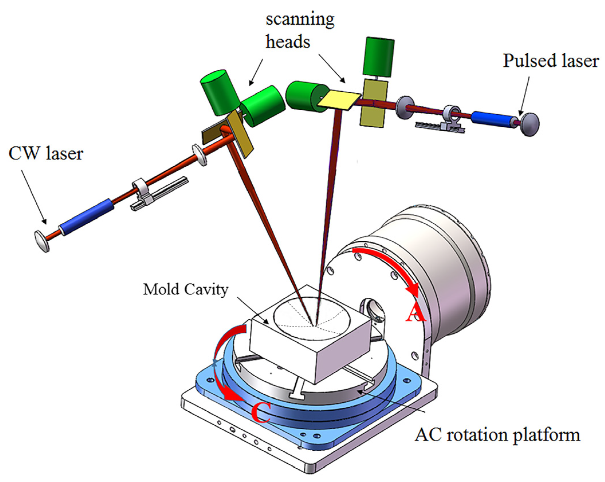
2.1. Dual-Beam Laser Polishing Device

A diagram of the experimental setup of the dual-beam laser polishing system [8] is presented in Figure 2. The system is composed of two 3D scan heads and a 2-axis CNC rotation table. The continuous wave (CW) laser beam implemented macro-polishing, while the pulsed-laser micro-polishing (PLμP) was conducted to achieve a smother final surface.

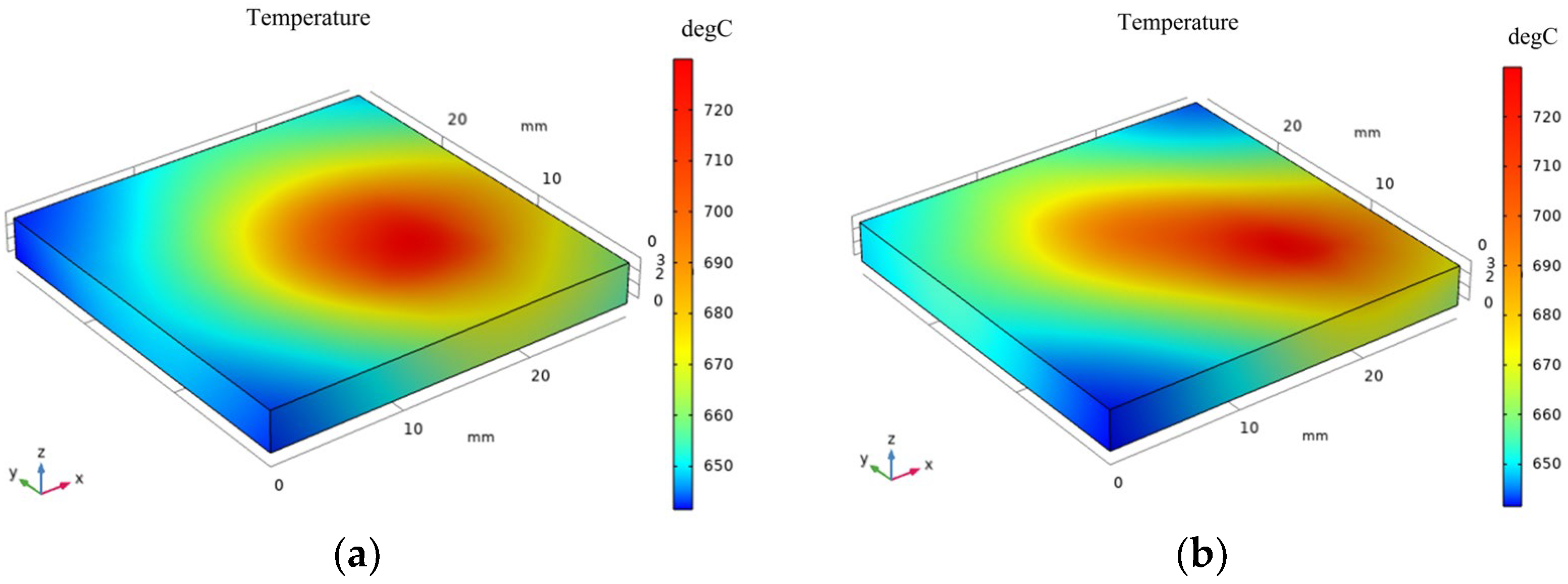
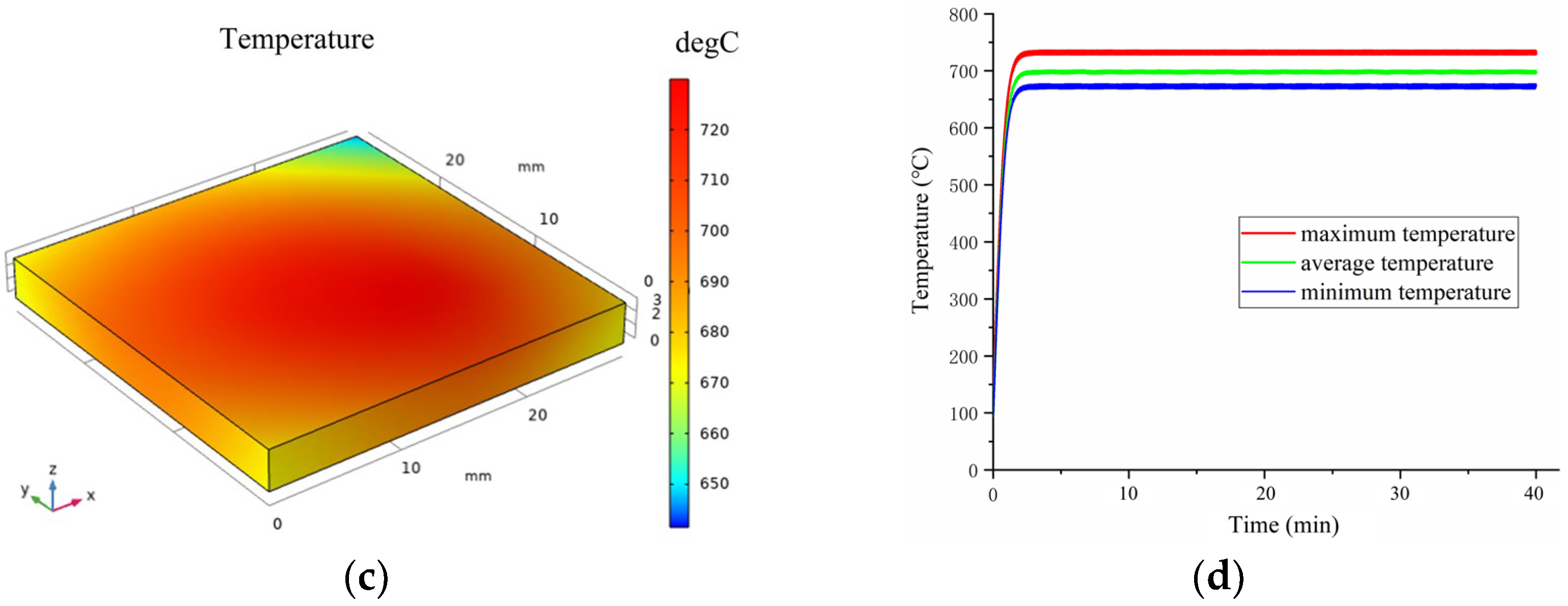
2.2. Numerical Simulation of Laser Annealing

Laser annealing is widely used to eliminate the residual stress of cold workpieces [25,26,27]. In this study, stress-relief annealing was performed on a laser-polished mold cavity by CW laser heating and holding to a high temperature (650–750 °C) over a certain cycle time. A numerical simulation of laser annealing was studied to optimize laser annealing parameters since laser stress-relief annealing is directly related to the parameters.
For theoretical analysis of surface temperature changes with heating area and time, the following assumptions were made.
(1)
The simulation is based on a 718H specimen with the size of 28 mm × 28 mm × 5 mm, since residual tensile stress is not able to be detected using any high-angle XRD approach for specimens exceeding this size.
(2)
The specimen surface is a homogeneous heat-conducting medium and can be treated as a medium with constant thermal diffusivity.
(3)
The impact of the laser beam defocusing on the specimen’s surface is not considered.
(4)
The specimen is laser-annealed in a process chamber with argon atmosphere without oxidation.
(5)
The specimen keeps the same thermal conductivity, k, in x, y, and z directions.
Carslaw and Jaeger [28] presented the basic governing equation of heat transfer, as follows:
ρ c T t = x ( k T x ) + y ( k T y ) + z ( k T z ) + Q
where ρ is material density (kg/m3), c is material specific heat capacity (J/(kg⋅K)), T is the temperature of the specimen’s surface at a specified time, t is time, and Q is the heat source (J/m3) in unit volume from the laser beam, depending on the power and diameter of the laser spot, with a top-hat pattern.
Furthermore, according to the characterization of the laser annealing process, its heating and holding temperature distribution at any time in any area of the specimen’s surface can be conducted as follows:
T ( x , y , z , t ) = α F k 4 K v ( 2 π ) 1 / 2 0 e z 2 2 μ e r f c Y + L ( 2 μ ) 1 / 2 e r f c Y L ( 2 μ ) 1 / 2 e r f c X + B + μ ( 2 μ ) 1 / 2 e r f c X B + μ ( 2 μ ) 1 / 2 d μ μ 1 / 2
where e r f c = ( 2 π ) 1 / 2 0 s e ξ 2 d ξ , X = v x 2 k , Y = v y 2 k , Z = v z 2 k , L = v l 2 k , B = v b 2 k , v is the scanning speed of the laser along the x or y direction, α is the absorptivity of the material, k is the thermal conductivity, μ is the step-over of laser scanning, and v is the speed of the laser scanning.
During the COMSOL simulation, laser annealing parameters can be optimized using 100 different combinations, for example, Figure 3a,b, show unacceptable simulation results using inappropriate parameters (CW laser was set at 220–300 W, scanning speed was 600–800 mm/s). Figure 3c presents that a more uniform surface temperature has been obtained, an acceptable simulation result, for which the power of the CW laser was set as 200 W, the scanning speed was 300 mm/s, and the step-over of laser scanning was 0.1 mm, resulting in an average temperature of 700 °C (shown in Figure 3d) within 40 min. Such temperature is a common practice of annealing alloyed steel in the conventional furnace annealing process.

2.3. Experiment of Dual-Beam Laser Polishing and CW Laser Annealing

Fourteen 718H specimens with the size of 28 mm × 28 mm × 5 mm were prepared and divided into two groups, whereby each group contained seven specimens for dual-beam laser polishing and CW laser annealing. First, the dual-beam laser polishing system [8] was used to polish the fourteen specimens, and the CW laser was used again to anneal the polished specimens. Table 1 shows the parameters of dual-beam laser polishing and CW laser annealing. The annealing cycle times of Group I and Group II were 10 and 40 min, respectively.
During dual-beam laser polishing of 718H steel, the CW laser implemented macro-polishing, and infrared pulsed-laser micro-polishing (PLμP) was conducted to polish the smoother surface finish in the meantime, resulting in the areal surface roughness dropping from its initial post-milling value of Sa 1.11 (±0.10) μm to a final post-polished value of Sa 0.16 (±0.09) μm. The surface morphology is shown in Figure 4. The roughness was measured by a confocal microscope (MarSurf CM Mobile, Mahr, Goettingen, Germany).

3. Results and Discussion

3.1. Residual Tensile Stress Measurements

The XRD (D8 Advance, Bruker, Billerica, MA, USA) pattern in Figure 5 demonstrates that both polished and annealed 718H specimens contained almost the same metallographic structures, mainly consisting of the martensite phase (α phase) and a small amount of the austenitic phase (γ phase), which was due to the high cooling rate during argon gas atomization in the chamber.
The cooling speed of the steel during dual-beam laser polishing was slower than in single CW laser polishing, since the pulsed laser often follows the CW laser and makes the steel cooling slower. Slow cooling of steels usually leads to a ferritic-perlitic or bainitic microstructure [9]. Martensite formation occurs during rapid solidification when carbon diffusion is suppressed or impeded. Martensite is formed between the martensite start and the martensite finish temperatures when austenitic materials are rapidly cooled down. Usually, the austenite is almost completely transformed into martensite so that only a small amount of retained austenite remains at room temperature. Therefore, the XRD diffraction peak (shown in Figure 5a) demonstrates that laser polishing can reduce the activation energy of martensite and promote a part of residual austenite to fully convert to martensite. Figure 5b presents that the phase composition after CW laser annealing remained almost the same as that after dual-beam laser polishing. A local area of the total laser annealing surface must have rapidly cooled down after laser scanning compared to conventional vacuum furnace annealing as a kink at 40–45 degrees (Figure 5b) was formed since the residual austenite was not fully decomposed into tempered martensite.
Regarding the instructions of the XRD instrument (Proto), the target material was Cr, used to measure the residual tensile stress for the martensite metallographic structure. Figure 6 shows that the average tensile stress on the 14 specimens’ surfaces was 638 MPa, resulting from the phase transformation which significantly affects the state of residual stress during rapid solidification, especially for steels with a high carbon content. In the process of laser-irradiating the material surface, the heat input leads to the hindrance of thermal expansion, and the boundary layer of the processed steel will generate residual compressive stress. When the steel melts, the residual stress on the molten surface will be released. In the condensation stage, the surrounding cold substrate hinders the shrinkage process of the solidified material at the solid/liquid interface, resulting in residual tensile stress. In addition, during the cooling phase, the phase transformation and the formation of precipitates change the state of residual stress. Figure 6 presents the results of tensile residual stress for Group I and Group II.

3.2. Residual Tensile Stress Relief

The yield strength of 718H steel at 200 °C was 925 MPa. According to Equations (2) and (3), it is obvious that the internal stress of 638 MPa easily caused fatigue cracks and SCC, and therefore stress-relief annealing is needed.
Table 1 shows that the CW laser, in addition, can also play the role of stress-relief annealing using the specified parameters. A fixed thermal imaging camera (A615, Flir, Portland, OR, USA) was used to detect the temperature of specimens’ surfaces when laser annealing. The actual annealing temperature was around 686–732 °C. Figure 5 shows that the tensile residual stress was around 370–410 MPa when the process cycle time of laser annealing was 10 min. However, it dropped to around 10–53 MPa when the cycle time was 40 min.
As a common practice, an annealing cycle time using a vacuum furnace is 2 h. Figure 5 also demonstrates that the average tensile residual stress dropped significantly from 638 to 53 MPa when the annealing cycle time changed from 10 to 40 min, and therefore no type of crack occurred in the injection process due to the small amount of stress when the process cycle time of laser annealing was over 40 min.
A scanning electron microscope (SEM, GeminiSEM300, SEISS, Oberkochen, Germany) was used to obtain SEM images of the polished surfaces to characterize and analyze their microstructure and properties. Figure 7 shows SEM images of cross-sections of both the polished layer and the annealed layer. The substrate microstructure of 718H steel exhibited distinctive segregation patterns generated by layer scanning, and three zones: the melt zone, heat-affected zone, and the substrate zone, still existed after laser annealing. Comparing Figure 7a,b, the thickness of the laser melt-zone layer after CW laser annealing increased from 43 to 50 µm. CW laser annealing can not only enhance the volume expansion of the transformation from original austenite to martensite but can also reduce the tensile residual stress that exists in the polished surface, or in some cases, form the compressive residual stress around the surface. This can enhance the fatigue strength of the injection mold cavity.
Detected by the FM-800 micro-Vickers hardness tester, the microhardness of the laser-polished surface was 553 HV at the depth of 10 μm, and then it decreased significantly with the increase of the depth until the depth reached 90 μm, as shown in Figure 8. The microhardness tended to be stable (370 HV), i.e., close to the hardness of the 718H substrate. Meanwhile, the microhardness of the laser-annealed surface was 542 HV at the depth of 10 μm, and then it decreased with the increase of the depth. When the depth was 90 μm, the microhardness of the laser-annealed surface was slightly higher than that of the laser-polished surface.

4. Conclusions

The purpose of this study was to explore a fast and effective method to reduce the tensile residual stress after laser polishing. The surface of 718H steel was polished by a dual-beam laser system consisting of a CW laser beam and a pulsed laser beam, and the surface finish was determined from an original value of Sa 1.11 μm to a final post-polished value of Sa 0.16 μm. However, the tensile residual stress increased to 638 MPa, causing fatigue cracks or stress corrosion cracks (SCC) on the mold cavity in the plastic injection process. The temperature of laser stress-relief annealing was determined through the numerical simulation, and the CW laser of the dual-beam laser system was used again to relieve the stress so that the final stress dropped to around 10–53 MPa when the cycle time of laser annealing was 40 min. Not only could the mold cavity be laser-polished and laser-annealed by the dual-beam laser system, but additionally the microstructure and microhardness did not significantly change after laser annealing, and the tensile residual stress caused by laser polishing approached to zero after laser annealing, so no fatigue crack or SCC occurred. The annealing efficiency was much higher than conventional vacuum furnace annealing without the extra expenses.
Most of the previous works mentioned above have focused on the study of laser polishing methodology, and a few of them introduced the measurement of the tensile residual stress, but no further approaches to stress-relief were elaborated. This study has presented an innovative method using the dual-beam laser system by which a mold cavity can be laser-polished and then laser-annealed, resulting in both elimination of tensile residual stress of the mold cavity and enhancement of its microhardness.
In laser polishing and annealing processes, many aspects of the research surrounding the topic remain focused on processes’ optimization to achieve both a finished surface and elimination of tensile residual stress based on the assumption of the COMSOL numerical simulation. This study was based on 178H mold steel, but can be applied in other mold steels such as ASSAB618H, S136H, and H13, etc. Recently, more and more mold makers are using additive manufacturing (AM) technology to make mold cores and cavities [29,30,31], whose materials are high-entropy alloys with anisotropy and heterogeneity of the microstructure [32,33,34]. Therefore, some items of the assumption of the COMSOL numerical simulation in this study become no longer valid. Future research will attempt to investigate the effect of dual-beam laser polishing and annealing of AM high-entropy alloys, so as to explore an effective approach associated with both improvement of the surface finish and elimination of tensile residual stress.

Author Contributions

Conceptualization, X.X., X.C. and Y.Z.; data curation, X.X., X.C. and Y.Z.; formal analysis, X.X., X.C. and M.L.; funding acquisition, X.X. and Y.Z.; methodology, X.X., X.C.; project administration, Y.Z. and M.L.; resources, M.L. and Y.Z.; software, Y.Z. and Y.L.; writing, X.X., X.C., Y.Z. and Y.L. All authors have read and agreed to the published version of the manuscript.

Funding

This research was funded by the Science and Technology Project of Guangdong Province (No. 2021A0505030013), the Scientific Research Project of General Universities in Guangdong Province (Nos. 2021KCXTD058 and 2022ZDZX3073), the Shenzhen Science and Technology Plan (No. JSGG20210420091802007), the Guangdong Provincial Education Science Planning Project (No. 2021GXJK541), and the Guangdong Higher Vocational and Technical College Education Reform and Practice Project (No. GDJG2021394).

Institutional Review Board Statement

Not applicable.

Informed Consent Statement

Not applicable.

Data Availability Statement

The data that support the findings of this study are available from the corresponding author upon reasonable request.

Conflicts of Interest

The authors declare no conflict of interest.

References

  1. Miller, J.D.; Tutunea-Fatan, O.R.; Bordatchev, E.V. Experimental analysis of laser and scanner control parameters during laser polishing of H13 steel. Procedia Manuf. 2017, 10, 720–729. [Google Scholar] [CrossRef]
  2. Yung, K.C.; Xiao, T.Y.; Choy, H.S.; Wang, W.J.; Cai, Z.X. Laser polishing of additive manufactured CoCr alloy components with complex surface geometry. J. Mater. Process. Tech. 2018, 262, 53–64. [Google Scholar] [CrossRef]
  3. Fu, Y.; Wang, X.; Gao, H.; Wei, H.; Li, S. Blade surface uniformity of blisk finished by abrasive flow machining. Int. J. Adv. Manuf. Tech. 2016, 84, 1725–1735. [Google Scholar] [CrossRef]
  4. Pyka, G.; Kerckhofs, G.; Papantoniou, I.; Speirs, M.; Schrooten, J.; Wevers, M. Surface Roughness and Morphology Customization of Additive Manufactured Open Porous Ti6Al4V Structures. Materials 2013, 6, 4737–4757. [Google Scholar] [CrossRef] [PubMed] [Green Version]
  5. Shiou, F.-J.; Hsu, C.-C. Surface finishing of hardened and tempered stainless tool steel using sequential ball grinding, ball burnishing and ball polishing processes on a machining centre. J. Mater. Process. Technol. 2008, 205, 249–258. [Google Scholar] [CrossRef]
  6. Chang, C.-S.; Chen, T.-H.; Li, T.-C.; Lin, S.-L.; Liu, S.-H.; Lin, J.-F. Influence of laser beam fluence on surface quality, microstructure, mechanical properties, and tribological results for laser polishing of SKD61 tool steel. J. Mater. Process. Technol. 2016, 229, 22–35. [Google Scholar] [CrossRef]
  7. Bhaduri, D.; Penchev, P.; Batal, A.; Dimov, S.; Soo, S.L.; Sten, S.; Harrysson, U.; Zhang, Z.; Dong, H. Laser polishing of 3D printed mesoscale components. Appl. Surf. Sci. 2017, 405, 29–46. [Google Scholar] [CrossRef]
  8. Zhou, Y.Q.; Zhao, Z.Y.; Zhang, W.; Xiao, H.B.; Xu, X.M. Experiment study of rapid laser polishing of freeform steel surface by dual-beam. Coatings 2019, 9, 324. [Google Scholar] [CrossRef] [Green Version]
  9. Temmler, A.; Liu, D.; Preußner, J.; Oeser, S.; Luo, J.; Poprawe, R.; Schleifenbaum, J.H. Influence of laser polishing on surface roughness and microstructural properties of the remelted surface boundary layer of tool steel H11. Mater. Design 2020, 192, 1018689. [Google Scholar] [CrossRef]
  10. Bordatchev, E.; Hafiz, A.M.K.; Tutunea-Fatan, O.R. Performance of laser polishing in finishing of metallic surfaces. Int. J. Adv. Manuf. Technol. 2014, 73, 35–52. [Google Scholar] [CrossRef]
  11. Paris, P.C.; Erdogan, F. A critical analysis of crack propagation laws. J. Basic Engng 1973, 85, 528–534. [Google Scholar] [CrossRef]
  12. Novikov, Y.A.; Zoteev, V.S. Fatigue crack propagation in steels with different yield strengths. Met. Sci. Heat Treat. 1977, 19, 465–468. [Google Scholar] [CrossRef]
  13. Russell, H.J. Stress-Corrosion Cracking Materials Performance and Evaluation, 2nd ed.; ASM International: Almere, The Netherlands, 2017. [Google Scholar]
  14. Chen, X.; Karasz, E.; Badwe, N.; Sieradzki, K. Dynamic fracture and dealloying induced stress-corrosion cracking. Corros. Sci. 2021, 187, 109503. [Google Scholar] [CrossRef]
  15. Yan, J.J.; Zheng, D.L.; Li, H.X.; Jia, X.; Sun, J.F.; Li, Y.L.; Qian, M.; Yan, M. Selective laser melting of H13: Microstructure and residual stress. J. Mater. Sci. 2017, 52, 12476–12485. [Google Scholar] [CrossRef]
  16. Preussner, J.; Oeser, S.; Pfeiffer, W.; Temmler, A.; Willenborg, E. Microstructure and residual stresses of laser remelted surfaces of a hot work tool steel. Int. J. Mater. Res. 2014, 105, 328–336. [Google Scholar] [CrossRef]
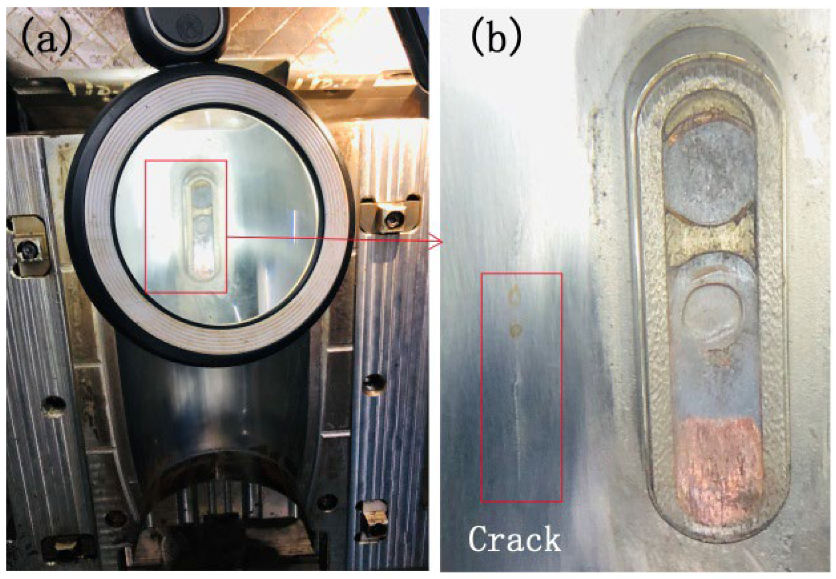
  17. Dong, J. Analysis on Cavity Surface Cracking of a Mould for Computer Keyboard Plastics. Heat Treat. 2015, 1, 51–54. (In Chinese) [Google Scholar]
  18. Manco, E.; Cozzolino, E.; Astarita, A. Laser polishing of additively manufactured metal parts: A review. Surf. Eng. 2022, 38, 217–233. [Google Scholar] [CrossRef]
  19. Gisario, A.; Barletta, M.; Veniali, F. Laser polishing: A review of a constantly growing technology in the surface finishing of components made by additive manufacturing. Int. J. Adv. Manuf. Technol. 2022, 120, 1433–1472. [Google Scholar] [CrossRef]
  20. Obeidi, M.A.; McCarthy, E.; O’Connell, B.; Ahad, I.U.; Brabazon, D. Laser Polishing of Additive Manufactured 316L Stainless Steel Synthesized by Selective Laser Melting. Materials 2019, 12, 991. [Google Scholar] [CrossRef] [Green Version]
  21. Li, J.; Jin, Y.; Chang, Y.; Zuo, D. Finite element simulation and experimental study of single-laser track in laser polishing of Ti6Al4V. Int. J. Adv. Manuf. Technol. 2022, 121, 4571–4581. [Google Scholar] [CrossRef]
  22. Yung, K.; Wang, W.; Xiao, T.; Choy, H.; Mo, X.; Zhang, S.; Cai, Z. Laser polishing of additive manufactured CoCr components for controlling their wettability characteristics. Surf. Coatings Technol. 2018, 351, 89–98. [Google Scholar] [CrossRef]
  23. Richter, B.; Blanke, N.; Werner, C.; Vollertsen, F.; Pfefferkorn, F.E. Effect of Initial Surface Features on Laser Polishing of Co-Cr-Mo Alloy Made by Powder-Bed Fusion. JOM 2018, 71, 912–919. [Google Scholar] [CrossRef]
  24. Meylan, B.; Calderon, I.; Le, Q.T.; Wasmer, K. Investigations of surface defects during laser polishing of tool steel. Procedia CIRP 2020, 94, 942–946. [Google Scholar] [CrossRef]
  25. Meylan, B.; Masserey, A.; Boillat, E.; Calderon, I.; Wasmer, K. Thermal Modelling and Experimental Validation in the Perspective of Tool Steel Laser Polishing. Appl. Sci. 2022, 12, 8409. [Google Scholar] [CrossRef]
  26. Le-Quang, T.; Shevchik, S.A.; Meylan, B.; Vakili-Farahani, F.; Olbinado, M.P.; Rack, A.; Wasmer, K. Why is in situ quality control of laser keyhole welding a real challenge? Procedia CIRP 2018, 74, 649–653. [Google Scholar] [CrossRef]
  27. Hunter, B.; Aldwell, B.; Jenkins, R.; Lupoi, R. A study on the feasibility of laser annealing to relieve residual stresses in cold spray coatings. Procedia CIRP 2018, 78, 91–96. [Google Scholar] [CrossRef]
  28. Carslaw, H.S.; Jaeger, J.C. Conduction of Heat in Solids, 2nd ed.; Clarenden Press: Oxford, UK, 1959. [Google Scholar]
  29. Biondani, F.; Bissacco, G.; Tang, P.T.; Hansen, H.N. Additive Manufacturing of Mould Inserts with Mirror-like Surfaces. Procedia CIRP 2018, 68, 369–374. [Google Scholar] [CrossRef]
  30. Brooks, H.; Brigden, K. Design of conformal cooling layers with self-supporting lattices for additively manufactured tooling. Addit. Manuf. 2016, 11, 16–22. [Google Scholar] [CrossRef] [Green Version]
  31. Roy, M.; Dickens, T.J. Additive technology of soluble mold tooling for embedded devices in composite structures: A study on manufactured tolerances. Addit. Manuf. 2017, 15, 78–86. [Google Scholar] [CrossRef] [Green Version]
  32. Park, J.M.; Choe, J.; Park, H.K.; Son, S.; Jung, J.; Kim, T.-S.; Yu, J.-H.; Kim, J.G.; Kim, H.S. Synergetic strengthening of additively manufactured (CoCrFeMnNi)99C1 high-entropy alloy by heterogeneous anisotropic microstructure. Addit. Manuf. 2020, 35, 101333. [Google Scholar] [CrossRef]
  33. Mirsayar, M. A generalized criterion for fatigue crack growth in additively manufactured materials—Build orientation and geometry effects. Int. J. Fatigue 2021, 145, 106099. [Google Scholar] [CrossRef]
  34. Kok, Y.; Tan, X.; Wang, P.; Nai, M.; Loh, N.; Liu, E.; Tor, S. Anisotropy and heterogeneity of microstructure and mechanical properties in metal additive manufacturing: A critical review. Mater. Des. 2018, 139, 565–586. [Google Scholar] [CrossRef]
Figure 1. A long crack in a mold cavity: (a) 718H mold cavity and (b) scale of the crack.
Coatings 12 01822 g001
Figure 2. Dual-beam laser polishing system.
Coatings 12 01822 g002
Figure 3. Laser annealing temperature simulation: (a,b) unacceptable results, (c) an optimized result, and (d) temperature distribution during annealing time.
Coatings 12 01822 g003aCoatings 12 01822 g003b
Figure 4. The roughness measurement of the 718H specimen: (a) Sa 1.11 μm before polishing and (b) Sa 0.16 μm after polishing.
Coatings 12 01822 g004
Figure 5. The XRD profiles of (a) laser-polished and (b) laser-annealed specimens.
Coatings 12 01822 g005
Figure 6. Measurement of tensile residual stress for Group I and Group II.
Coatings 12 01822 g006
Figure 7. SEM images of cross-sections: (a) laser polishing and (b) laser annealing.
Coatings 12 01822 g007
Figure 8. Microhardness of laser polishing and laser annealing.
Coatings 12 01822 g008
Table 1. Parameters of the dual-beam laser polishing and CW laser annealing.
Laser ParametersDual-Beam Laser PolishingAnnealing
CW LaserPulsed LaserCW Laser
Power600 W80 W200 W
Wavelength1080 nm1064 nm1064 nm
Beam profile patternTop-hatTop-hatTop-hat
Pulse durationN/A1.3 μsN/A
Spot diameter0.47 mm0.32 mm0.47 mm
Scanning speed100 mm/s150 mm/s300 mm/s
Step-over0.1 mm0.1 mm0.1 mm
Scanning routeZigzagSquare waveZigzag
Process cycle time1.6 min1.6 min10, 40 min
Publisher’s Note: MDPI stays neutral with regard to jurisdictional claims in published maps and institutional affiliations.

