
Longitudinal Magneto-Optical Kerr Effect of Nanoporous CoFeB and W/CoFeB/W Thin Films


Abstract
:
1. Introduction
2. Experimental Section
2.1. Sample Fabrication and Characterization
2.2. Simulation
3. Results and Discussion
CoFeB Thickness Dependent MOKE of Nanoporous CoFeB/AAO/Al Thin Films
4. Conclusions and Perspectives
Author Contributions
Funding
Institutional Review Board Statement
Informed Consent Statement
Data Availability Statement
Conflicts of Interest
References
- Nikitov, S.A.; Kalyabin, D.V.; Lisenkov, I.V.; Slavin, A.N.; Pavlov, E.S. Magnonics: A new research area in spintronics and spin wave electronics. Phys.-Uspekhi 2015, 58, 1099–1128. [Google Scholar] [CrossRef]
- Zimnyakova, P.E.; Ignatyeva, D.O.; Karki, D.; Voronov, A.A.; Shaposhnikov, A.N.; Berzhansky, V.N.; Levy, M.; Belotelov, V.I. Two-dimensional array of iron-garnet nanocylinders supporting localized and lattice modes for the broadband boosted magneto-optics. Nanophotonics 2021, 11, 119–127. [Google Scholar] [CrossRef]
- Gabbani, A.; Petrucci, G.; Pineider, F. Magneto-optical methods for magnetoplasmonics in noble metal nanostructures. J. Appl. Phys. 2021, 129, 211101. [Google Scholar] [CrossRef]
- Rave, W.; Zueco, E.; Schäfer, R.; Hubert, A. Observations on high-anisotropy single crystals using a combined Kerr/magnetic force microscope. J. Magn. Magn. Mater. 1998, 177–181, 1474–1475. [Google Scholar] [CrossRef]
- Wolfgang, R.; Rudolf, S.; Alex, H. Quantitative observation of magnetic domains with the magneto-optical Kerr effect. J. Magn. Magn. Mater. 1987, 65, 7–14. [Google Scholar] [CrossRef]
- Hoffmann, V.; Schäfer, R.; Appel, E.; Hubert, A.; Soffel, H. First domain observations with the magneto-optical Kerr effect on Ti-ferrites in rocks and their synthetic equivalents. J. Magn. Magn. Mater. 1987, 71, 90–94. [Google Scholar] [CrossRef]
- Buchanan, K.S.; Krichevsky, A.; Freeman, M.R.; Meldrum, A. Magnetization dynamics of interacting iron nanocrystals in SiO2. Phys. Rev. B 2004, 70, 174436. [Google Scholar] [CrossRef]
- Sepúlveda, B.; Calle, A.; Lechuga, L.M.; Armelles, G. Highly sensitive detection of biomolecules with the magneto-optic surface-plasmon-resonance sensor. Opt. Lett. 2006, 31, 1085–1087. [Google Scholar] [CrossRef]
- Rizal, C. Magneto-optic SPR-based Biosensors. In Proceedings of the 2020 Photonics North (PN), Niagara Falls, ON, Canada, 26–28 May 2020; p. 1. [Google Scholar] [CrossRef]
- Rizal, C.; Belotelov, V. Sensitivity comparison of surface plasmon resonance (SPR) and magneto-optic SPR biosensors. Eur. Phys. J. Plus 2019, 134, 1–6. [Google Scholar] [CrossRef]
- Ayareh, Z.; Mahmoodi, S.; Moradi, M. Magneto-plasmonic biosensing platform for detection of glucose concentration. Optik 2019, 178, 765–773. [Google Scholar] [CrossRef]
- David, S.; Polonschii, C.; Luculescu, C.; Gheorghiu, M.; Gáspár, S.; Gheorghiu, E. Magneto-plasmonic biosensor with enhanced analytical response and stability. Biosens. Bioelectron. 2015, 63, 525–532. [Google Scholar] [CrossRef]
- Chandra, S.; Cozart, J.; Biswas, A.; Lee, S.; Chanda, D. Magnetoplasmons for Ultrasensitive Label-Free Biosensing. ACS Photonics 2021, 8, 1316–1323. [Google Scholar] [CrossRef]
- You, W.; Tengdin, P.; Chen, C.; Shi, X.; Zusin, D.; Zhang, Y.; Gentry, C.; Blonsky, A.; Keller, M.; Oppeneer, P.M.; et al. Revealing the Nature of the Ultrafast Magnetic Phase Transition in Ni by Correlating Extreme Ultraviolet Magneto-Optic and Photoemission Spectroscopies. Phys. Rev. Lett. 2018, 121, 077204. [Google Scholar] [CrossRef] [PubMed] [Green Version]
- Belyaev, V.K.; Rodionova, V.V.; Grunin, A.A.; Inoue, M.; Fedyanin, A.A. Magnetic field sensor based on magnetoplasmonic crystal. Sci. Rep. 2020, 10, 7133. [Google Scholar] [CrossRef] [PubMed]
- Campo, G.; Pineider, F.; Bonanni, V.; Albino, M.; Caneschi, A.; de Julián Fernández, C.; Innocenti, C.; Sangregorio, C. Magneto-optical probe for investigation of multiphase Fe oxide nanosystems. Chem. Mater. 2015, 27, 466–473. [Google Scholar] [CrossRef] [Green Version]
- Baselt, D.R.; Lee, G.U.; Natesan, M.; Metzger, S.W.; Sheehan, P.E.; Colton, R.J. A biosensor based on magnetoresistance technology. Biosens. Bioelectron. 1998, 13, 731–739. [Google Scholar] [CrossRef]
- Buznikov, N.A.; Safronov, A.P.; Orue, I.; Golubeva, E.V.; Lepalovskij, V.N.; Svalov, A.V.; Chlenova, A.A.; Kurlyandskaya, G.V. Modelling of magnetoimpedance response of thin film sensitive element in the presence of ferrogel: Next step toward development of biosensor for in-tissue embedded magnetic nanoparticles detection. Biosens. Bioelectron. 2018, 117, 366–372. [Google Scholar] [CrossRef]
- Brzeska, M.; Panhorst, M.; Kamp, P.B.; Schotter, J.; Reiss, G.; Pühler, A.; Becker, A.; Brückl, H. Detection and manipulation of biomolecules by magnetic carriers. J. Biotechnol. 2004, 112, 25–33. [Google Scholar] [CrossRef]
- Chen, L.; Bao, C.-C.; Yang, H.; Li, D.; Lei, C.; Wang, T.; Hu, H.-Y.; He, M.; Zhou, Y.; Cui, D.-X. A prototype of giant magnetoimpedance-based biosensing system for targeted detection of gastric cancer cells. Biosens. Bioelectron. 2011, 26, 3246–3253. [Google Scholar] [CrossRef]
- Yang, Z.; Wang, H.; Dong, X.; Yan, H.; Lei, C.; Luo, Y. Giant magnetoimpedance based immunoassay for cardiac biomarker myoglobin. Anal. Methods 2017, 9, 3636–3642. [Google Scholar] [CrossRef]
- Caballero, B.; García-Martín, A.; Cuevas, J.C. Hybrid magnetoplasmonic crystals boost the performance of nanohole arrays as plasmonic sensors. ACS Photonics 2016, 3, 203–208. [Google Scholar] [CrossRef]
- Manera, M.G.; Ferreiro-Vila, E.; Garcia-Martin, J.M.; Garcia-Martin, A.; Rella, R. Enhanced antibody recognition with a magneto-optic surface plasmon resonance (MO-SPR) sensor. Biosens. Bioelectron. 2014, 58, 114–120. [Google Scholar] [CrossRef]
- Schmitte, T.; Theis-Br$ouml$hl, K.; Leiner, V.; Zabel, H.; Kirsch, S.; Carl, A. Magneto-optical study of the magnetization reversal process of Fe nanowires. J. Phys. Condens. Matter 2002, 14, 7525–7538. [Google Scholar] [CrossRef]
- Tillmanns, A.; Oertker, S.; Beschoten, B.; Guentherodt, G.; Leighton, C.; Schuller, I.K.; Nogues, J. Magneto-optical study of magnetization reversal asymmetry in exchange bias. Appl. Phys. Lett. 2006, 89, 202512. [Google Scholar] [CrossRef] [Green Version]
- Huang, D.; Lattery, D.; Wang, X. Materials engineering enabled by time-resolved magneto-optical kerr effect for spintronic applications. ACS Appl. Electron. Mater. 2021, 3, 119–127. [Google Scholar] [CrossRef]
- Zeng, H.T.; Read, D.; Petit, D.; Jausovec, A.V.; O’Brien, L.; Lewis, E.R.; Cowburn, R.P. Combined electrical and magneto-optical measurements of the magnetization reversal process at a domain wall trap. Appl. Phys. Lett. 2009, 94, 103113. [Google Scholar] [CrossRef] [Green Version]
- Sedrpooshan, M.; Ahmadvand, H.; González, D.L.; van Dijken, S. Magneto-optical study of anomalous magnetization reversal in the presence of anisotropy dispersion in CoPd thin films. Phys. Rev. B 2018, 98, 214444. [Google Scholar] [CrossRef] [Green Version]
- Beaurepaire, E.; Merle, J.C.; Daunois, A.; Bigot, J.Y. Ultrafast spin dynamics in ferromagnetic nickel. Phys. Rev. Lett. 1996, 76, 4250–4253. [Google Scholar] [CrossRef]
- Lambert, C.-H.; Mangin, S.; Varaprasad, B.S.D.C.S.; Takahashi, Y.K.; Hehn, M.; Cinchetti, M.; Malinowski, G.; Hono, K.; Fainman, Y.; Aeschlimann, M.; et al. All-optical control of ferromagnetic thin films and nanostructures. Science 2014, 345, 1337–1340. [Google Scholar] [CrossRef] [Green Version]
- Zdorovets, M.V.; Kozlovskiy, A.L.; Shlimas, D.I.; Borgekov, D.B. Phase transformations in FeCo—Fe2CoO4/Co3O4-spinel nanostructures as a result of thermal annealing and their practical application. J. Mater. Sci. Mater. Electron. 2021, 32, 16694–16705. [Google Scholar] [CrossRef]
- Vinnik, D.A.; Starikov, A.Y.; Zhivulin, V.E.; Astapovich, K.A.; Turchenko, V.A.; Zubar, T.y.I.; Trukhanov, S.V.; Kohout, J.; Kmječ, T.; Yakovenko, O.; et al. Changes in the structure, magnetization, and resistivity of BaFe12−xTixO19. ACS Appl. Electron. Mater. 2021, 3, 1583–1593. [Google Scholar] [CrossRef]
- Feldmann, J.; Youngblood, N.; Wright, C.D.; Bhaskaran, H.; Pernice, W.H.P. All-optical spiking neurosynaptic networks with self-learning capabilities. Nature 2019, 569, 208–214. [Google Scholar] [CrossRef] [PubMed] [Green Version]
- Liu, X.D.; Xu, Z.; Gao, R.X.; Chen, Z.F.; Lai, T.S.; Du, J.; Zhou, S.M. Improved time-resolved magneto-optical Kerr effect technique and dynamic magnetization reversal mechanism of perpendicularly magnetized L10 FePt films. arXiv 2009, arXiv:0812.1360. [Google Scholar]
- Lei, C.X.; Man, Z.S.; Tang, S.L. Extraordinary optical transmission and enhanced magneto-optical faraday effect in the cascaded double-fishnet structure with periodic rectangular apertures. Curr. Opt. Photonics 2020, 4, 134–140. [Google Scholar] [CrossRef]
- Li, N.; Tang, T.; Li, J.; Luo, L.; Sun, P.; Yao, J. Highly sensitive sensors of fluid detection based on magneto-optical optical Tamm state. Sens. Actuators B Chem. 2018, 265, 644–651. [Google Scholar] [CrossRef]
- Borovkova, V.; Ignatyeva, D.O.; Sekatskii, S.K.; Karabchevsky, A.; Belotelov, V.I. High-Q surface electromagnetic wave resonance excitation in magneto-photonic crystals for super-sensitive detection of weak light absorption in near-IR. Photonics Res. 2020, 8, 57–63. [Google Scholar] [CrossRef]
- Qin, J.; Deng, L.; Xie, J.; Tang, T.; Bi, L. Highly sensitive sensors based on magneto-optical surface plasmon resonance in Ag/CeYIG heterostructures. AIP Adv. 2015, 5, 017118. [Google Scholar] [CrossRef] [Green Version]
- Knyazev, G.A.; Kapralov, P.O.; Gusev, N.A.; Kalish, A.N.; Belotelov, V.I. Magnetoplasmonic Crystals for Highly Sensitive Magnetometry. ACS Photonics 2018, 5, 4951–4959. [Google Scholar] [CrossRef]
- Tishkevich, D.I.; Grabchikov, S.S.; Lastovskii, S.B.; Trukhanov, S.V.; Zubar, T.I.; Vasin, D.S.; Trukhanov, A.V. Correlation of the synthesis conditions and microstructure for Bi-based electron shields production. J. Alloys Compd. 2018, 749, 1036–1042. [Google Scholar] [CrossRef]
- Zubar, T.I.; Fedosyuk, V.M.; Trukhanov, S.V.; Tishkevich, D.I.; Michels, D.; Lyakhov, D.; Trukhanov, A.V. Method of surface energy investigation by lateral AFM: Application to control growth mechanism of nanostructured NiFe films. Sci. Rep. 2020, 10, 14411. [Google Scholar] [CrossRef]
- Lordan, D.; Wei, G.; McCloskey, P.; O’Mathuna, C.; Masood, A. Origin of perpendicular magnetic anisotropy in amorphous thin films. Sci. Rep. 2021, 11, 3734. [Google Scholar] [CrossRef]
- Zhang, W.; Wang, Y.; Wang, Q.; Belotelov, V.I.; Song, Y. Surface and Interface Engineering Multilayered Nanopore Films for Enhanced Fabry–Pérot Interferences. J. Phys. Chem. C 2018, 122, 29457–29463. [Google Scholar] [CrossRef]
- Zhang, W.; Li, J.; Ding, X.; Pernod, P.; Tiercelin, N.; Song, Y. Tunable Magneto-Optical Kerr Effects of Nanoporous Thin Films. Sci. Rep. 2017, 7, 2888. [Google Scholar] [CrossRef] [PubMed] [Green Version]
- Zhang, W.; Wang, Q.; Zhao, C.; Song, Y. The optical cavity enhanced magneto-optical Kerr effect signals of AAO/Al-based CoFeB nanostructure arrays. Opt. Commun. 2019, 437, 44–49. [Google Scholar] [CrossRef]
- Hoffmann, M.A.; Sharma, A.; Matthes, P.; Okano, S.; Hellwig, O.; Ecke, R.; Zahn, D.R.T.; Salvan, G.; Schulz, S.E. Spectroscopic ellipsometry and magneto-optical Kerr effect spectroscopy study of thermally treated Co60Fe20B20 thin films. J. Phys. Condens. Matter 2020, 32, 055702. [Google Scholar] [CrossRef]
- Sharma, A.; Hoffmann, M.A.; Matthes, P.; Hellwig, O.; Kowol, C.; Schulz, S.E.; Zahn, D.R.T.; Salvan, G. Crystallization of optically thick films of CoxFe80−xB20: Evolution of optical, magneto-optical, and structural properties. Phys. Rev. B 2020, 101, 776. [Google Scholar] [CrossRef]
- Song, Y.; Wang, Y.; Li, B.B.; Fernandes, C.; Ruda, H.E. Interface interaction induced ultra-dense nanoparticles assemblies. Nanoscale 2013, 5, 6779–6789. [Google Scholar] [CrossRef] [PubMed]
- Hindmarch, A.T.; Rushforth, A.W.; Campion, R.P.; Marrows, C.H.; Gallagher, B.L. Origin of in-plane uniaxial magnetic anisotropy in CoFeB amorphous ferromagnetic thin-films. Phys. Rev. B 2011, 83, 1417–1425. [Google Scholar] [CrossRef] [Green Version]
- García, D.; Muñoz, J.L.; Kurlyandskaya, G.; Vázquez, M.; Ali, M.; Gibbs, M.R.J. Induced anisotropy, magnetic domain structure and magnetoimpedance effect in CoFeB amorphous thin films. J. Magn. Magn. Mater. 1999, 191, 339–344. [Google Scholar] [CrossRef]
- Diaz-Valencia, B.F.; Mejia-Salazar, J.R.; Oliveira, O.N., Jr.; Porras-Montenegro, N.; Albella, P. Enhanced Transverse Magneto-Optical Kerr Effect in Magnetoplasmonic Crystals for the Design of Highly Sensitive Plasmonic (Bio)sensing Platforms. ACS Omega 2017, 2, 7682–7685. [Google Scholar] [CrossRef] [PubMed]
- Zak, J.; Moog, E.R.; Liu, C.; Bader, S.D. Universal approach to magneto-optics. J. Magn. Magn. Mater. 1990, 89, 107–123. [Google Scholar] [CrossRef]
- Rakić, A.D. Algorithm for the determination of intrinsic optical constants of metal films: Application to aluminum. Appl. Opt. 1995, 34, 4755–4767. [Google Scholar] [CrossRef] [PubMed]
- Zhang, W.; Song, Y. Fundamental in Thin Films and Coatings, 1st ed.; Song, Y., Ed.; Wiley-VCH: Weinheim, Germany, 2021; Volume 1, pp. 66–75. [Google Scholar] [CrossRef]
- Sepulveda, B.; Gonzalez-Diaz, J.B.; Garcia-Martin, A.; Lechuga, L.M.; Armelles, G. Plasmon-induced magneto-optical activity in nanosized gold disks. Phys. Rev. Lett. 2010, 104, 147401. [Google Scholar] [CrossRef] [Green Version]
- Bonanni, V.; Bonetti, S.; Pakizeh, T.; Pirzadeh, Z.; Chen, J.; Nogues, J.; Vavassori, P.; Hillenbrand, R.; Akerman, J.; Dmitriev, A. Designer magnetoplasmonics with nickel nanoferromagnets. Nano Lett. 2011, 11, 5333–5338. [Google Scholar] [CrossRef] [PubMed]
- Chen, J.; Albella, P.; Pirzadeh, Z.; Alonso-Gonzalez, P.; Huth, F.; Bonetti, S.; Bonanni, V.; Akerman, J.; Nogues, J.; Vavassori, P.; et al. Plasmonic nickel nanoantennas. Small 2011, 7, 2341–2347. [Google Scholar] [CrossRef] [Green Version]


| t | 12 | 22 | 51 | 55 | 58 | 61 | 66 | 73 | 88 |
|---|---|---|---|---|---|---|---|---|---|
| χ | 0.04 | 0.05 | 0.09 | −1.96 | −1.61 | −3.61 | −2.36 | −4.56 | −4.34 |
| Hc | 460.0 | 168.2 | 242.9 | 175.0 | 83.2 | 157.3 | 95.1 | 107.6 | 123.2 |
| θS | 14.5 | 3.3 | 22.6 | −85.0 | −48.6 | −179.9 | −144.9 | −155.0 | −124.7 |
| t | 95 | 103 | 110 | 120 | 129 | 140 | 246 | 266 | 372 |
| χ | −4.26 | −4.68 | −1.69 | −1.21 | −2.69 | −0.11 | −1.58 | −0.81 | −6.61 |
| Hc | 134.1 | 143.2 | 98.3 | 130.5 | 127.8 | 27.9 | 76.6 | 53.2 | 48.5 |
| θS | −145.0 | −138.2 | −106.8 | −70.0 | −130.9 | −32.4 | −125.2 | −70.4 | −131.1 |
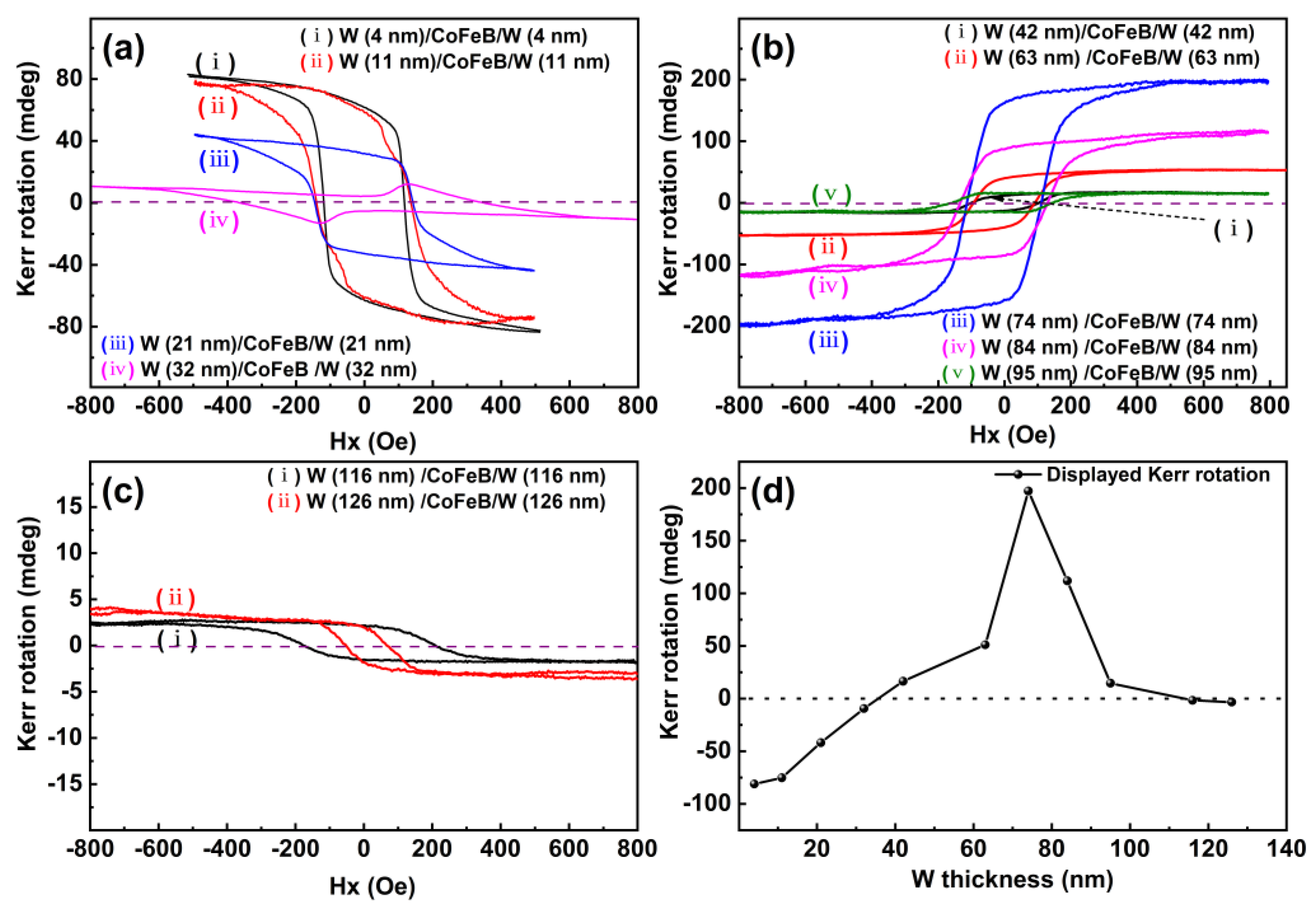
| t | 4 | 11 | 21 | 32 | 42 | 63 | 74 | 84 | 95 | 116 | 126 |
|---|---|---|---|---|---|---|---|---|---|---|---|
| χ | −3.04 | −1.26 | −1.02 | 0.142 | 0.311 | 0.813 | 2.98 | 1.40 | 0.33 | −0.03 | −0.06 |
| Hc | 116.5 | 142.5 | 145.5 | 354.9 | 101.1 | 153.0 | 111.8 | 131.9 | 151.8 | 194.3 | 59.1 |
| θS | −85.4 | −75.2 | −42.6 | 9.6 | 16.9 | 16.1 | 198.6 | 109.0 | 15.5 | −2.0 | −2.9 |
Publisher’s Note: MDPI stays neutral with regard to jurisdictional claims in published maps and institutional affiliations. |
© 2022 by the authors. Licensee MDPI, Basel, Switzerland. This article is an open access article distributed under the terms and conditions of the Creative Commons Attribution (CC BY) license (https://creativecommons.org/licenses/by/4.0/).
Share and Cite
Zhang, W.; Chen, Z.; Belotelov, V.I.; Song, Y. Longitudinal Magneto-Optical Kerr Effect of Nanoporous CoFeB and W/CoFeB/W Thin Films. Coatings 2022, 12, 115. https://doi.org/10.3390/coatings12020115
Zhang W, Chen Z, Belotelov VI, Song Y. Longitudinal Magneto-Optical Kerr Effect of Nanoporous CoFeB and W/CoFeB/W Thin Films. Coatings. 2022; 12(2):115. https://doi.org/10.3390/coatings12020115
Chicago/Turabian StyleZhang, Weiwei, Zhanghua Chen, Vladimir I. Belotelov, and Yujun Song. 2022. "Longitudinal Magneto-Optical Kerr Effect of Nanoporous CoFeB and W/CoFeB/W Thin Films" Coatings 12, no. 2: 115. https://doi.org/10.3390/coatings12020115
APA StyleZhang, W., Chen, Z., Belotelov, V. I., & Song, Y. (2022). Longitudinal Magneto-Optical Kerr Effect of Nanoporous CoFeB and W/CoFeB/W Thin Films. Coatings, 12(2), 115. https://doi.org/10.3390/coatings12020115