1. Introduction
Precision products made of heat-resistant nickel alloys, such as Inconel 718 and Nicrofer 5219 Nb, are more than 50% of the mass of modern aircraft gas turbine engines due to the unique physical and mechanical properties of these materials and their ability to function under conditions of increased contact stresses, high operating temperatures, and corrosive and erosive effects of vapors and gases [
1,
2,
3,
4,
5]. The scientific group of Kumar, A., in their study of the formation of fatigue cracks in gas turbine engines [
1], studied the liquid corrosion of a nickel alloy with lead, which was a critical factor in the actual destruction of gas turbine engines with a relatively short product life cycle, according to their study and the official conclusion of the investigation. A new approach based on empirical scaling from microstructural dimensions using the simple El Haddad small-crack model and the cracks’ length parameter to correlate the small- and large-crack data for nickel-based alloys by adjusting the small-crack driving force was critically evaluated by the research group of McClung, R.C. in [
2]. The strengths and limitations of the simple El Haddad model were explored and compared. The research group of Sahoo, B. [
3] discussed the bulk properties of a military aircraft’s gas turbine engine parts that determine the product life and are decided by the aero-thermal degradation and microstructure degeneration of nickel alloy despite aluminide coating. The coarsening of gamma prime and the degeneration of carbides in the bulk material microstructure were evaluated. The research group of Volkov, A.M. [
4] investigated the microstructure of gas turbine engine aircraft parts after heat treatment of granulated heat-resistant nickel alloys characterized by high long-term strength at 750 °C and confirmed the phase stability of the material. The research group of Martinez, S. [
5] evaluated the misalignment and geometry distortion of the standard National Institute of Standards and Technology test artifact in the Inconel 718 alloy using laser powder bed fusion. The results of numerical simulations showed that the laser path strategy favors a thermal gradient that partially induces geometrical distortions.
In machining nickel alloys, the working surfaces of cutting tools experience an unfavorable combination of loads, such as the developing high temperatures in the cutting zone combined with high specific pressures on the contact pads contributing to the intense adhesion of the chips coming off with a rake face and the intense abrasion of the flank face in direct contact with the workpiece to be machined [
6,
7,
8,
9,
10]. The highlighted issues significantly reduce the service life of carbide cutters, increase the probability of cutting edges’ brittle fracture, worsen the machined surface quality, and force technologists to reduce the cutting speed and, consequently, the milling productivity.
The following outstanding works can be distinguished from the known scientific groups working in Inconel 718 machining [
11,
12,
13]. Urbikain Gorka et al. [
11], in their recent work, considered the tool geometry, tool position, and laser scanning strategy influence on microstructures, crystallographic textures, and grain morphologies of Inconel 718 samples produced by laser powder bed fusion. The layer thickness of the produced parts influences the evolution of the cutting force in milling.
Wang, B. and Liu, Z.Q. [
12] developed a complex approach in a systematization of the last achievements of the influence of cutting parameters and cutting environments, the structure and material of cutting tools on the fundamental factors that govern the machined surface integrity.
Ulutan, D. et al. [
13] reviewed surface integrity problems such as residual stresses, white layer and work hardening layers, and microstructural alterations to improve surface qualities of nickel products. They highlighted in their study the following cutting factors that influence surface integrity: cutting speed, feed rate, depth of cut, tool geometry and preparation, tool wear, and workpiece properties.
Wang, J.T. et al. [
14] researched the influences of cutting parameters, cutting fluid, and spindle angles on the residual stresses in the ball end milling Inconel 718. They concluded that residual stress distributions are highly influenced by cutting parameters such as the depth of cut and cutting speed. Milling with cooling induces more compressive stresses, and the magnitude of the residual stresses increases in the tensile direction with the increase in spindle angles. In their opinion, the larger the machining parameters, the better for controlling residual stresses in ball end milling that can dramatically influence the service life and performance of the aircraft parts.
Denkena, B. et al., in their work [
15], highlight the problem of convex surface quality of a nickel alloy part after additive manufacturing. To solve the global problem of the controlled surface finishing via five-axis ball end milling, they proposed a dynamic simulation model to achieve the required surface quality of aircraft parts.
It should be noted that in the last five years, only four research groups devoted their studies to the ball end milling of nickel aircraft alloys, despite this topic of using last generation complex coatings for the complex tools deserving more attention in the context of high-temperature cutting conditions.
Mills made of cemented carbide with a spherical cutting end to machine spatially complex surfaces of parts made of heat-resistant nickel alloys are more complicated and costly in terms of manufacturing. However, unlike traditional end mills with a rectangular end, they do not have pronounced stress concentrates, which minimizes the probability of brittle fracture of the cutting edges (if rational cutting conditions are assigned) [
16,
17].
In recent years, the range of carbide end mills produced by the tool industry has been so broad that enterprises now have an alternative tool selection to solve any technological problem. A variety of end mills with a spherical cutting part has a conical barrel-shaped geometry that smoothly turns into a spherical end. It is an advanced and promising tool for finishing curved surfaces, which, like the classic ball end mills, should not be deprived of the attention of specialists.
Production experience shows that the milling efficiency of precision products made of heat-resistant nickel alloy primarily depends on the cutting ability of the tool. Therefore, the task of ensuring maximum wear resistance of end mills emerges into prominence [
18,
19,
20,
21,
22] in combination with an acceptable performance by applying a high cutting speed and reducing the time of auxiliary operations (for tool change). It should be noted that the preservation of a longer time period of cutting ability of ball-shaped end mills aims to solve another technological problem, this being ensuring the possibility of part typical surfaces machining in one setup without the retraction and new plunge-in of the tool. Changing the cutter directly during machining often leads to an error in the shape and size of the part and the appearance of gouges and other unacceptable defects for the aircraft industry [
23,
24,
25].
Considering that high-temperature nickel alloys have low thermal conductivity and a high tendency to adhere to cemented carbide, the state of the cutting edge (with rake and flank faces forming it) will determine the end mill’s cutting ability. The temperature near the cutting edge determines the tool wear intensity in milling Inconel 718 alloys to a greater extent [
26,
27,
28]. However, despite the existing possibilities of using more heat-resistant oxide and nitride tool ceramics, cemented carbide will remain the primary tool material in the long term due to less brittleness [
29,
30,
31,
32]. For example, Fernandez-Lucio, P. et al. [
33], after testing cemented carbide (uncoated and coated with AlTiN, the thickness of the coating was not provided) and SiAlON ceramics in milling Inconel(R) 718 until the end of their useful life (criterion was tool wear reaching 0.3 mm or a fatal failure), stated that coated carbide is not ultimately suitable for milling at higher speeds, unlike tool ceramics.
The application of wear-resistant coatings based on nitrides and oxides of refractory metals aims to increase the microhardness of the tool contact pads, ensuring their physicochemical passivity (reducing the coefficient of friction) concerning the material to be machined, a combination of which should increase the end mill’s cutting ability [
34,
35,
36,
37].
It is known from classical works in the field of the theory of cutting materials that the power of heat-generating sources in shaping largely depends on the friction forces on the rake- and flank-working faces of the tool and the work of forces on the contact pads that cause wear [
38,
39]. Therefore, their effectiveness in solving the problem of increasing the tool’s cutting ability in cutting nickel alloys [
40,
41,
42,
43] will, in many respects, depend on the ability of coatings to reduce frictional interaction on the contact pads (while maintaining heat resistance).
Diamond-like carbon (DLC) coatings consist of carbon atoms with both diamond and graphite-like bonds [
44,
45,
46] and have pronounced advantages over nitride and oxide coatings from the point of view of providing a reduced coefficient of friction on the tool working surfaces. However, the use of DLC coatings for cutting tools under the conditions of cutting difficult-to-machine alloys is limited by their relatively low heat resistance and increased level of internal stresses, which leads to a decrease in the strength of the adhesive bond [
47,
48]. Until recently, the main area of DLC coating application was the high-speed machining of aluminum alloys and other non-ferrous metals when the level of power loads was relatively low and the temperature in the cutting zone did not exceed 450–480 °C. In addition, DLC coatings are in their most comfortable conditions in such a temperature range, and many authors have experimentally confirmed their effectiveness in cutting “light” processed materials [
49]. The authors of this work provided a threefold increase in tool wear resistance and a significant improvement in the quality of the machined part by single-layer hydrogenated DLC coating (a-C:H type) deposition to end mills when machining the aluminum alloy AlCuMg
2.
In recent years, great progress has been made by various research teams in the area of improving DLC coatings [
50,
51,
52,
53]. Various technological approaches are associated with alloying coatings by various metals and metalloids, in particular silicon, to stabilize the tribological properties of DLC coatings under high-temperature heating conditions. Transition and intermediate sublayers are preliminarily formed, which have proven to be highly effective under certain conditions to reduce the level of stresses in the DLC coating deposed on the cemented carbide and to ensure increased strength of the coating adhesive bond to the substrate [
54,
55,
56]. Modern DLC coatings remain underestimated although they have specific prospects in increasing the tool cutting ability in milling heat-resistant nickel alloys.
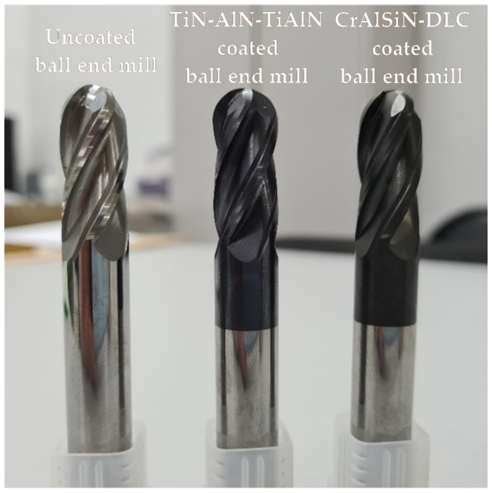
The aim of this work was to study the ability of DLC coatings based on a-C:H:Si with a CrAlSiN nitride sublayer to withstand thermal loads in a wide temperature range (varied by choosing a different speed milling mode such as 150, 200, and 250 m/min). The efficiency of DLC coating deposed to cemented carbide ball end mills was evaluated compared to uncoated ball end mills and the samples coated with the well-proven multi-layer gradient TiN–AlN–TiAlN coating under high-temperature conditions (at 20, ~550, ~650, ~850 °C). During the experiments, the particular focus was on assessing the temperature in the cutting zone as the most important and, in many ways, informative parameter. The thermo-EMF (electromotive force) was recorded, which was converted into temperature values according to the corresponding calibration charts using the method of natural thermocouple in the cutting zone. For the first time, the authors compared the behavior of CrAlSiN–DLC and TiN–AlN–TiAlN coatings deposed to ball end mills under operating conditions at different cutting temperatures, with the results of high-temperature tribological tests received on a friction machine. The new experimental results on the assessment of the cutting ability of cemented carbide ball end mills with CrAlSiN–DLC coatings at different levels of thermal loads as well as establishing the effect of coatings on the state of the machined surface of a nickel alloy part can be a step towards expanding the areas of technological application of DLC coatings and their implementation based on new technical solutions for the needs of the aviation industry.
2. Materials and Methods
2.1. Cutting Tools and Materials to Be Machined
Spherical end mills were used for the experiments, designed for machining free-form surfaces (FFS) in parts made of difficult-to-machine materials.
Figure 1 shows a general view of the design of the end mill. Spherical end mills with the following design and geometrical parameters were used: number of teeth was 4; diameter of cut was 12 mm; ball nose radius was 6 mm; length of cut was 30 mm; overall length was 75 mm.
KFM 39 tungsten-cobalt carbide manufactured by Konrad Micro Drill (Kulmbach, Germany) was used as a tool material.
Table 1 shows the characteristics of the tool carbide.
The material to be machined was a nickel-based, heat-resistant alloy XH45MBTJuBP, according [
57] (the closest analog of Inconel 718).
Table 2 shows the composition of the machined alloy. The basis of the specified alloy is an austenitic solid solution of the nickel–chromium–iron system. In practice, the alloy is used for the highly loaded elements of load-bearing structures and other parts of gas turbine engines operating in various climatic conditions at temperatures up to 800 °C. The workpiece used in the research was a hot-rolled bar that was 55 mm in diameter. The alloy had a hardness of 320 (on the HB scale) and strength of 1080 MPa.
2.2. Technology and Equipment for the Coatings’ Deposition on End Mills
The technology of coating spherical end mills included three main stages:
The authors [
58] have discussed the (Cr,Al,Si)N-(DLC-Si) system composite coatings on the (Al
2O
3 + TiC) ceramic cutting tool and the performance properties. The studies substantiated the need for the deposition a (Cr,Al,Si)N transition sublayer between a ceramic tool and the DLC-Si coating and the influence of the Si content on the life of a ceramic cutting tool. The research group of Jeon, Y. [
59] investigated the tribological properties of ultrathin films with a single metal layer of chromium, nickel, and titanium between the Si substrate and the thin film. Three different metals (chromium, nickel, and titanium) were used as the interlayers between the Si substrate and DLC thin film, then, the Cr interlayer was found to be the most suitable to improve the tribological behavior of the DLC coating. Both of these works used etching in a gas discharge.
A. Metel [
60] developed a vapor source, the flat target of a hollow cathode, isolated from the cathode and sputtered by 1–4-keV argon ions. The higher energy of the atoms improved the quality of Ti(3)SiB(2) coatings, their deposition rate of 10–20 mu·m/h at 1 A current in the target circuit, and 3-keV energy of sputtering ions that was one order of magnitude higher in comparison with the target sputtering in a planar magnetron. In [
61], it was shown that the formed plasma of a broad beam of fast neutral molecules for cutters nitriding proved that fast molecules play a leading role in gas ionization. An anode immersed in the plasma reduces plasma nonuniformity to 10% when the discharge voltage amounts to 200–300 V and raises plasma density by an order of magnitude. A new beam-assisted deposition technique featuring fast neutral molecule beams instead of conventional ion beams [
62] ensured better treatment stability and reliability, eliminated the damage of conductive films with unipolar arcs, and substantially reduced the number of beam-induced defects in semiconductive and dielectric coatings. An experimental study of a fast argon atom beam source [
63] was carried out to research the influence of the zone diameter of a homogeneous substrate etching by a broad beam of fast argon atoms accelerated between a plasma emitter inside the hollow cathode and secondary plasma in the working vacuum chamber. The diameter of the homogeneous etching zone was mainly influenced by the angular characteristics of accelerated particles in the grid plane. The diameter was raised with a decrease in energy and an increase in the beam current. A source of slow metal atoms produced beam-assisted deposition of cutting tool coatings [
64]. Fast gas molecules allowed keeping the ratio of metal atom flow density to that of fast molecules constant and maintaining uniformity of the coating properties. Fast molecules are produced due to charge-exchange collisions of ions accelerated by bias difference between a plasma emitter inside the source and secondary plasma inside the chamber.
The method of vacuum arc deposition was used for the deposition of a two-component nitride coating TiN–AlN–TiAlN and a three-component sublayer CrAlSiN, in which the metal component of the plasma is formed upon evaporation of the cathode material from the cathode spots of the arc discharge, and the reactive gas is supplied to the working zone in an ionized state. A plasma-chemical, gas-phase deposition of carbon condensate was used for the DLC coating’s deposition through a chemical reaction and the decomposition of the gas mixture components (the original technology, patented by Platit, Selzach, Switzerland, was taken as a basis).
A functional diagram of a hybrid vacuum-plasma setup, which makes it possible to form coatings by vacuum-arc and gas-phase deposition, is shown in
Figure 2. The working vacuum chamber is made in the form of a hexagonal prism, on the flanges of which a pair of electric arc evaporators with cathodes are located, equipped with arc magnetic field systems and control of the trajectory of motion of the cathode spots. The cathodes have the shape of a truncated cone and are obtained by sintering powder materials in a vacuum. Two oppositely installed cathodes (Ti and Al) participated in the work during the deposition of the TiN–AlN–TiAlN coating, Cr and AlSi, respectively, and the working gases were supplied to the chamber via a multi-channel gas injection system (each channel was equipped with an individual flow regulator) during the CrAlSiN sublayer deposition.
The original design of the setup allows for planetary rotation of the machined end mills due to the work table rotation and tool sample holders. It is possible to form both monolayer coatings and multilayer coatings with alternating layers, particularly TiN–AlN, by setting the required rotation frequencies of the table and holders and their synchronization by using the installation control system. When the samples enter the plasma flow generated in a vacuum by an electric arc evaporator, a layer is deposed from the material from which the evaporator cathode is made. The next layer is deposited after turning the working table into another evaporator’s zone, and the samples ingress into the plasma flow region. The process is repeated depending on the designed structure and the required coating thickness.
An Ar and N2 gas mixture in a 95% N2 and 5% Ar ratio was admitted into the chamber. The pressure was set at 0.9 Pa for the nitride coating’s deposition. The temperature in the chamber was maintained with the help of heaters at a level of 550 °C. The following currents were supplied to the cathodes to ensure the most dense and uniform plasma flow: during TiN–AlN–TiAlN deposition, for Ti cathode—100 A, for Al—120 A; during the deposition of CrAlSiN, for the Cr cathode—100 A, for AlSi—120 A. Negative bias of 50 V was supplied from the reference voltage source to the planetary rotation device, and the process of condensation of coatings was carried out. The total deposition time of the TiN–AlN–TiAlN coating was 120 min, and the CrAlSiN sub-coat was 65 min. The formation of the DLC-based outer coating consisted of three stages. At the beginning of the process, 10 min before the completion of the formation of the preceding nitride sublayer of CrAlSiN, tetramethylsilane was supplied into the vacuum chamber, bringing the gas mixture to a ratio of 80% N2, 15% (CH3)4Si, and 5% Ar (to form a transition layer and voltage reduction in the DLC coating). Then, the vacuum-arc evaporators were turned off, and the temperature in the chamber dropped to 200 °C (the temperature was further maintained by the heaters). A negative bias of 500 V was applied to the planetary rotation device, and a glow discharge was ignited. A gradient DLC layer was formed when a gas mixture was supplied into the chamber in a ratio of 75% N2, 20% Ar, and 5% (CH3)4Si and at a pressure of 1.5 Pa during the first 20 min. In the final stage, within 1 h 40 min of a gas mixture ratio of 45% C2H2, 53% Ar, and 2% (CH3)4Si and a chamber pressure of 0.8 Pa, as a result of the decomposition of acetylene, carbon atoms were deposited on the end mills’ surface in the form of a DLC coating. It should be noted that the Si content in the carbon film, which affects the DLC coating characteristics, depends on the (CH3)4Si content in the gas mixture, which is controlled by the gas flow rate in the channel. Earlier research by the authors found that the rational Si content in the DLC coating is 3–4%. In this work, the ratio of gases in the mixture at the final stage of DLC coating formation was established based on this.
2.3. Evaluation of the Coated Specimens’ Characteristics Outside the Cutting Process
Scanning electron microscopy (SEM) was conducted using a TESCAN VEGA microscope (Tescan, Brno, Czech Republic) with a thermionic tungsten cathode and TESCAN MIRA3 (Tescan, Brno, Czech Republic) to assess the morphology of the formed coatings. The structure and thickness of the formed coatings on the specified equipment were examined by SEM analysis of thin sections of the working part of the end mills by a specialized technological line of Struers (Struers ApS, Ballerup, Denmark).
Transmission electron microscopy (TEM) was used to study structure and thickness. For this purpose, thin lamellas were cut out of the coated sample using a Quanta 200 3D focused ion beam setup (FEI Company, Hillsboro, OR, USA); they were further examined on a transmission microscope JEM-2100F (JEOL, Tokyo, Japan).
The principle of nano-identification by a three-edged Berkovich pyramid was used in the Nano Hardness Tester by CSEM instruments (Alpnach, Switzerland) [
51] to assess the microhardness of the coated hard-alloy samples. Such measurements are considered the most informative because they minimize the influence of the tool substrate hardness on the values of the estimated characteristics of the coatings. In the experiments, the penetration depth of the indenter was 380 nm and the applied load was 4.0 mN.
A preliminary analysis of the abrasion resistance of the end mills with two coatings was carried out through rapid tests on a Calotest instrument from CSM Instruments (Alpnach, Germany). A rotating sphere was placed on the test samples of cutters with a load of 0.5 N and an abrasive suspension was fed into the contact zone. Suspension particles in the contact zone and applied external forces led to local abrasion of the cutters’ surface layer areas. As the tests were carried out directly on the tool specimens (in the form of a cylinder) rather than on flat samples, the wear hole had the shape of an ellipse and not a circle, as is the case in standard tests. Therefore, optical analysis of the size of the holes made it possible to determine the volume of the abraded surface at different periods.
The surface layer friction coefficient of hard-alloy samples made of KFM 39 with coatings was evaluated on a TNT friction machine from Anton Paar TriTec (Graz, Austria). For tribological tests, experimental specimens were made in the form of disks with a diameter of 18 mm and a height of 6 mm. The 6 mm ball-like counter bodies were made of a nickel alloy to be machined. The ball-on-disc scheme was used, corresponding to the ASTM G99 17 standard. During the tests, the following modes were established: an applied load of 1 N; a radius of movement of 2 mm; a sliding speed of 100 mm/s. The tests were carried out over a wide range of temperature exposures.
2.4. Evaluating the Cutting Performance of Coated End Mills during Milling
Evaluation of the cutting ability of ball end mills was carried out on a CTX beta 1250 TC turning and milling machine from DMG MORI (Bielefeld, Germany) equipped with a Siemens CNC system (Munich, Germany). The machining strategy scheme that was used in the tests was as follows (
Figure 3a). The end mill that was fixed in a collet chuck performed a main rotational movement at cutting speed
vc and moved along the workpiece axis (feed rate,
vf) at a depth of cut
ap. The workpiece to be machined in the form of a bar was provided an auxiliary rotational movement at speed
vw. The cutting process was carried out at the following modes:
vc of 150, 200, and 250 m/min;
fz of 0.05 mm/tooth;
ap of 0.3 mm;
vw of 1.7 m/min.
The cutting conditions were chosen based on the need to provide a wide range of thermal loads on the cutting part of end mills with DLC coatings and also taking into account the recommendations of the leading manufacturers of cemented carbide ball end mills for cutting hard-to-cut alloys, such Guhring (Albstadt, Germany) and Karnasch Professional Tools (Heddesheim, Germany) and others.
During the experiments, the research team discussed adding up the speeds for a summary value taking into account vw. However, such a difference does not show a significant impact on the temperature in the cutting zone.
The test specimens of the tool were divided into 9 groups (each group had 5 specimens): end mills without coating, end mills with TiN–AlN–TiAlN coating, end mills with CrAlSiN–DLC coating. These were tested at cutting speeds of 150, 200, and 250 m/min. There were at least 10 repetitions for each type of coating and ball end mill in the determined cutting conditions.
The milling time until the tool wear on the flank face reached the critical value of 0.3 mm was taken as a criterion for the cutting ability of ball end mills’ evaluation. A Stereo Discovery V12 metallographic optical microscope from Carl Zeiss (Oberkochen, Germany) was used for wear evaluation. Each of the four teeth of the ball end mill was measured, and the average of the reported wear was taken into account in collecting static data.
Figure 3b shows a diagram of the measurement of the tool wear on the flank face of a ball end mill using the built-in micro-meter ruler of the microscope. At the end of the tests, graphs of changes in wear values versus milling time were drawn, based on which, the average time until the critical wear reaching moment was calculated.
The state of the workpiece surface layer is an object of close attention for technologists at enterprises because the cutting of nickel alloys is accompanied by an increased adhesive interaction of the tool and workpiece materials, and a large number of adhesions are present not only on the working surfaces of the tool but also directly on the workpiece (chip particles are firmly welded to the processed part) [
7,
17,
65]. However, a large amount of stock material at the cutting edge often requires additional operations before abrasive machining can be finished. In addition, their mechanical removal can damage the surface layer of the critical parts. Therefore, the state of the machined part surface was examined on a Hommel Tester T8000 profilograph–profilometer from JENOPTIK Industrial Metrology (Villingen-Schwenningen, Germany) when assessing the cutting ability of the tool in addition to dimensional wear.
2.5. Temperature Assessing in the Cutting Zone Using the Natural Thermocouple Method
The natural thermocouple method is one of the simplest and most accurate methods for experimentally estimating the temperature under the cutting conditions compared to the methods of artificial and semi-artificial thermocouples. When the workpiece and the cutter are combined into a closed electrical circuit, the magnitude of the thermoelectromotive force occurring in the thermoelement is proportional to the temperature of the sliding “junction” of the formed thermocouple. A thermocouple “junction” can be presented as a large number of parallel-connected thermocouples with internal resistance. It is important to note that the temperature in the contact stabilizes within 5 s from the start of cutting and it allows us to estimate the average temperature of the cutting zone without focusing on one of the contact surfaces with an error of no more than 6 °C.
The study of the temperature on the contact pads during cutting was carried out by the method of a natural thermocouple (the average temperature during milling was estimated) [
66,
67,
68,
69].
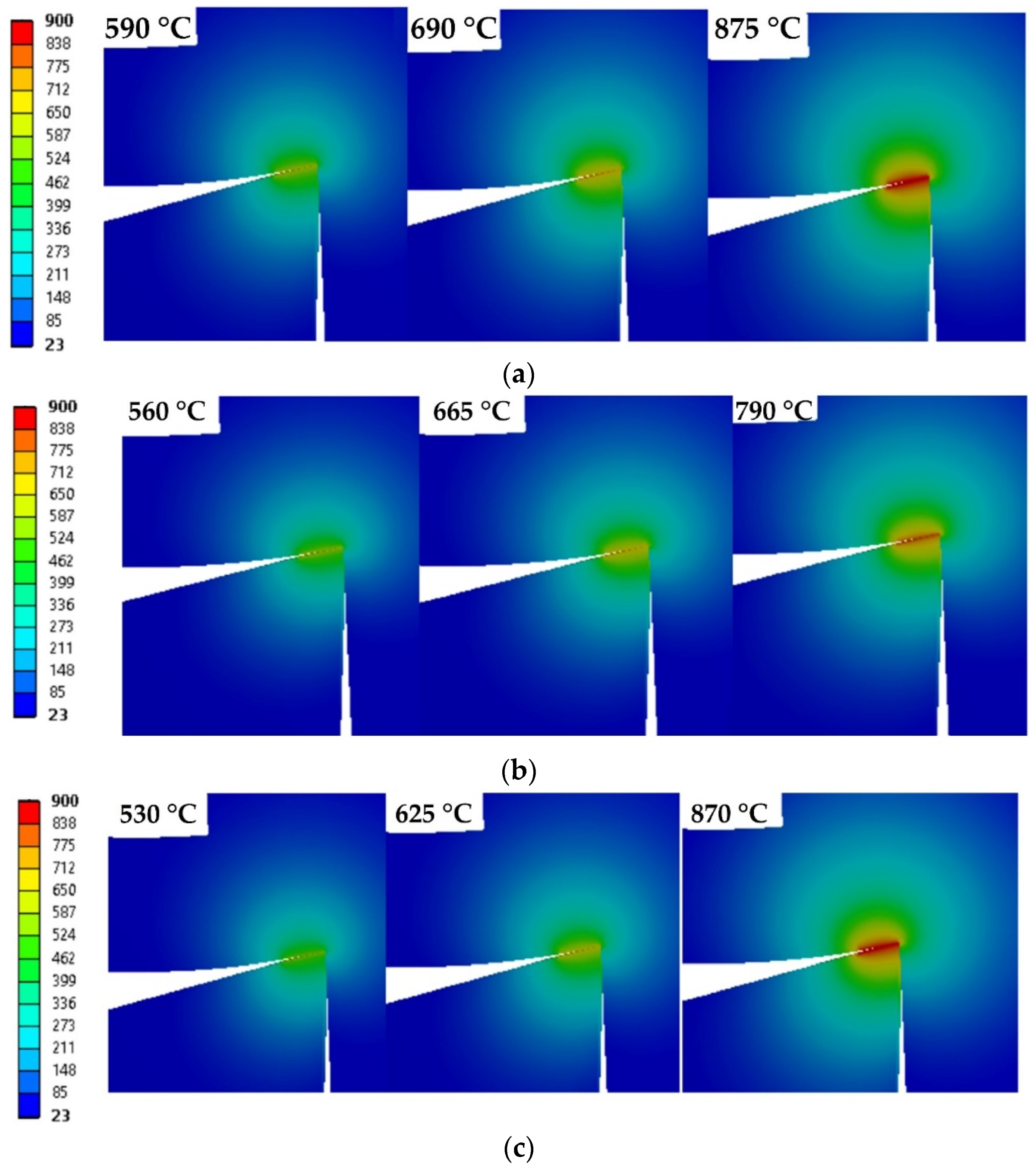
Figure 4a shows a functional diagram of a system for measuring the cutting temperature, implemented based on a turning–milling machine. Visualization of the temperature distribution at the cutting edge and adjacent layers of tool material is shown in
Figure 4b. During the experiments, the part and the end mill were isolated from each other in order to eliminate errors from the so-called “parasitic” thermo-EMF. Thermo-EMF was measured in the range of 5.0–5.5 min after the start of cutting at the stage of the steady-state process (after the running-in stage). Mercury current collectors and a recording device of the Endim 622 model (VEB Feinmesszeugfabrik, Suhl, Germany) were used to register and record the thermo-EMF value. Experimental data were received and processed in an information processing and control rack.
The application package TemPole (Ufa Aviation State Technical University, Ufa, Russia) was used to process the array of data on the measurement of thermo-EMF. An original system was used for calibrating natural thermocouples based on a differential heating scheme and a model of local contact of single microroughness of the tool and processed materials to convert the obtained values of thermo-EMF during cutting into temperatures. A distinctive feature of this approach is that the natural thermocouple was calibrated at different pressures at the contact during loading and unloading, and heating was carried out by an electro-contact method.
Figure 4c shows the calibration scheme for a natural thermocouple. The calibration process was based on a differential scheme. A model of local contact of a single microroughness of a tool was used as a hot junction of a thermocouple. It was made in the form of a two-sided spherical indenter made of tool material under a normal load, embedded in plane-parallel samples of a nickel alloy. In this case, the indenter was provided a rotational motion, and the lower sample was heated by the electrocontact method using a regulating transformer. The actual contact temperature was recorded with a control chromel–alumel thermocouple with a diameter of 0.03–0.05 mm and the Endim recording device, on which the thermo-EMF of a natural thermocouple was recorded. The heating temperature was changed due to a change in the strength of the transmitted electric current, the regulating transformer. The contact zone was heated by an electrical installation, which was a step-down and control transformer. The readings of the thermo-EMF of the control thermocouple during cooling and various modes of loading and unloading of the contact zone were recorded, and then they were converted to the corresponding temperature values according to the calibration tables. Comparison of temperature values while machining nickel alloy in a wide range of cutting speeds and visualization of the temperature distribution on the cutting edge and adjacent layers of tool material were carried out using a specialized module based on the Deform 3D software package from SFTC (Columbus, OH, USA).
4. Discussion
The results obtained regarding the increase in the resistance of the cemented carbide with coatings to abrasion (
Figure 6) demonstrate expected trends as the formed TiN–AlN–TiAlN and CrAlSiN–DLC coatings significantly increase the microhardness of the contact areas of the specimens. Lower abrasion of the CrAlSiN–DLC coating over most of the test distance has a similar character because the resistance to abrasive wear is determined not only by the microhardness of the contacting surfaces but also mainly by the friction coefficient on the contact pads. Optical analysis of worn holes shows that the rotating sphere quickly wipes through both variants of the coatings under the study, but the CrAlSiN–DLC coating is able to restrain the development of a wear center for a longer time. The finding can be explained by the so-called “edge effect”, which is when the coating remaining along the edges of the hole is capable of reducing the wear rate to a certain point. A similar mechanism was observed by various authors when studying the behavior of PVD coatings, in particular [
70].
However, the data on resistance to abrasive wear are not sufficient in predicting the coating’s behavior directly for cutting under the influence of increased temperature loads that are typical for milling nickel alloys. The results of tribological tests on a friction machine (
Figure 7) were obtained at different levels of thermal impact on the contact zone of two counter bodies, involving a tool hard alloy and a processed nickel alloy, which are of great research interest.
Figure 7a shows that nitride coatings are obviously and noticeably inferior to the DLC coating at room temperature, which was predictable when taking into account the experimental results previously obtained by the authors of the work in the study of the frictional behavior of various coatings in contact with a nickel alloy [
71].
The results of tribological tests when exposed to high temperatures, such as 550, 650, and 800 °C (
Figure 7b–c), can explain the effectiveness of the CrAlSiN–DLC coating in terms of increasing the tool cutting ability during milling at cutting speeds of 150 and 200 m/min (1.5 and 1.4 times). However, while milling at speeds of 250 m/min (
Figure 8) when elevated temperatures act on the cutting edge, the coating did not show any effect. For example, when analyzing the measured average temperatures of the contact pads of ball end mills with the CrAlSiN–DLC coating (
Figure 9), it can be seen that they were of 530, 620, and 870 °C at cutting speeds of 150, 200, and 250 m/min, respectively. As follows from authoritative works [
8,
9,
10,
17], the prevailing wear mechanism is the adhesive in such temperature conditions, which occurs due to continuous and repetitive gripping processes (cold welding) of the workpiece material and the tool. An increase in temperature promotes an increase in the adhesion component of the friction coefficient, intensifies the gripping processes, and increases the gripping area of the contacting surfaces and the amount of heat released during friction. Thus, when the temperature in the contact zone of two materials rises, an increase in the contact surfaces’ friction force and wear rate is expected. In this work, such conclusions were made for the machined material of an Inconel 718-type alloy, but the observed patterns are valid for a broad class of materials. The authors of [
72] drew similar conclusions for machining AISI 316 L stainless steel.
The CrAlSiN–DLC coating is quite efficient in operating at temperatures up to 650 °C; although the coefficient of friction increases markedly, the contact pads are able to restrain the gripping processes. An increase in temperature to 800 °C causes irreversible structural changes and loss of hardness of the DLC layer, and the friction conditions approach those of a cemented carbide. There is a slight decrease in the coefficient of friction, even at a temperature of 800 °C (
Figure 8), for the CrAlSiN–DLC coating, but this is definitely not enough to increase the tool cutting ability.
As long as the CrAlSiN–DLC coating exhibits a lower coefficient of friction at cutting speeds of 150 and 200 m/min, which corresponds to cutting temperatures of 530 and 620 °C, respectively, it contributes to the already described significant reduction in the intensification of adhesive gripping processes. The effect of the CrAlSiN–DLC coating at milling speeds of 150 and 200 m/min and the average cutting temperatures corresponding to these conditions of about 530 and 625 °C (
Figure 9) can be considered significant as the milling time to critical wear increases by 1.5 and 1.4 times. Furthermore, it immediately affects the condition of the surfaces in contact. Under these conditions, there is minimal stuck material on the surface of the machined part and the working surfaces of ball end mills. As can be seen in
Figure 8c, the cutting ability of ball end mills under such conditions increases only 1.1 times, which is insignificant.
The results of high-temperature tribological tests (
Figure 7) correlate well with the results obtained when assessing the cutting ability of ball end mills and can explain the surface condition of the machined workpiece (
Figure 10) and tool contact pads (
Figure 11), which were observed at different speeds and temperature conditions.
The coefficient of friction on the contact surfaces significantly depends on the level of thermal exposure, predetermines the wear intensity of the cutting part of the ball end mill in machining nickel alloys, and affects the state of the machined surface of the part.
The data presented in
Figure 9 at a cutting speed of 150 m/min demonstrate a critical pattern involving higher temperature and friction coefficient on the working surfaces of ball end mills without coating and with the TiN–AlN–TiAlN coating contributing to intense sticking of the nickel alloy to the active part cutting edge and directly onto the machined surface of the part, significantly worsening its condition. Many authors, particularly in the review, noted increased adhesion of the nickel alloy to the carbide tool and workpiece when using nitride coatings at cutting speeds up to 150 m/min [
73]. In the case of the CrAlSiN–DLC coating formed on the working surfaces, lower temperatures and friction coefficients are observed in the cutting zone, and there are barely noticeable deposits on the cutting edge. In this case, the surface condition of the part is significantly improved.
The higher cutting temperatures that occur at high milling speeds (250 m/min) and the increased coefficient of friction on the contact surfaces observed for ball end mills without coating and with CrAlSiN–DLC coating contribute to the sticking (“spreading”) of the nickel alloy on the cutting edge and flank face of the tool (
Figure 10). In addition, the presented SEM images of the distribution of nickel (particles of red color) on the tool’s working surfaces make it possible to visually evaluate the differences between cutters without coating and with two coating options.
The TiN–AlN–TiAlN coating showed noticeably lower values of the coefficient of friction and a higher cutting ability at a cutting speed of 250 m/min contrarily at a temperature of about 800 °C (although the coating showed an insignificant effect at cutting speeds of 150 and 200 m/min). That can be explained by the ability of such compounds to form so-called secondary structures [
74,
75,
76,
77,
78]. The TiAlN compound tends to oxidize and form relatively stable surface alumina oxide films. In machining at high cutting speeds, alumina films formed on the surface can limit the interaction of the underlying coating layers with the chip and workpiece material.
It can be concluded that as long as the CrAlSiN–DLC coating exhibits a lower coefficient of friction at cutting speeds of 150 and 200 m/min, which correspond to cutting temperatures of 530 and 620 °C, respectively, the coating contributes to the already described significant reduction in the intensification of adhesive gripping processes. Furthermore, it immediately affects the condition of the surfaces in contact. Under these conditions, there is minimal stuck material on the surface of the machined part and the working surfaces of ball end mills. Negative structural changes occurring in the CrAlSiN–DLC coating at a cutting speed of 250 m/min (at a cutting temperature of 870 °C) do not protect the contact surfaces, and the intensity of adhesion of the nickel alloy to the workpiece and the cutting tool is very high and similar to that observed for cutters without coating. On the contrary, the TiN–AlN–TiAlN coating, at cutting speeds of 150 and 200 m/min, does not have a noticeable effect on the formation of adhesions, but the intensity of nickel alloy adhesion to the workpiece and the working platforms of the end mill is significantly reduced at 250 m/min. This finding can be explained by the formation of the above-mentioned secondary structures, such as alumina-based films, which reduce the adhesive gripping.
5. Conclusions
The novelty of the current study lies in:
The research of the prospective architecture of the CrAlSiN–DLC coating (a-C:H:Si) deposed to the cemented carbide tool that had never been proposed before for machining nickel alloys.
The comparison of experimental results with the behavior of the sharply new-designed multilayer TiN–AlN–TiAlN coating deposed to the cemented carbide ball end mill.
The focus on the conditions of the cutting edge under the estimated thermal loads (up to ~850 °C) and quality of the machined part surface after milling in a wide speed range.
The practical significance of the work lies in:
Conducting experimental research in a condition close to the conditions of real production, which can have a possible short-term impact on the industry.
Formulating a real technological solution on the usage of a newly designed coating deposed to the commercial cemented carbide ball end mill with the proposed cutting conditions for convex surfaces of the aircraft part made of nickel alloy that can be immediately applied in the condition of the industrial production.
The main differences between this work and similar works are:
The development of experimental work in conditions close to those of real production, which is of fundamental importance for the industry.
Using a type of prospective coating never before proposed for the machining of difficult-to-machine alloys.
The orientation of the experimental part of the work, specifically on the behavior of the main cutting edge under conditions of thermal loads.
A comparison of the results obtained using the prospective architecture of the CrAlSiN–DLC coating with a sharply new multi-layer coating, which is one of the most promising in modern tool production.
The study of the operational behavior of coatings on the example of a complex profile tool.
The experimental studies showed that the temperature near the cutting edge is the parameter that limits the cutting ability of diamond-like carbon a-C:H:Si-coated ball end mills in cutting nickel alloys of the Inconel 718 type to a greater extent (in the conditions of dry milling). Studies demonstrate that the cutting ability of ball end mills at certain cutting temperatures correlates well with the tool material in the process of tribological tests when heated to temperatures of a similar level. Studying the frictional behavior of the cemented carbide surface layer with various coatings on a friction machine under high-temperature heating conditions is a suitable tool for express testing and for making decisions on the advisability of further testing the effectiveness of the coating on the machine when cutting nickel alloys.
Forming DLC based on a-C:H:Si coating with a pre-formed nitride CrAlSiN sublayer on the surface of cemented carbide ball end mills that are intended for processing heat-resistant alloys of the Inconel 718 type can significantly reduce the frictional interaction on the contact surfaces, and can thereby reduce the amount of heat generated by friction and reduce the temperature near the cutting edge, according to the technology described in this work. As a result, the CrAlSiN–DLC coating can be considered effective for solving the technological problem of increasing the cutting ability of the tool as well as for improving the condition of the machined surface and reducing the amount of stuck material that significantly degrades the quality of the machined part and intensifies the wear of the tool contact pads. However, it should be emphasized that the above is true only for conditions when the temperature effect on the surface layer of samples with CrAlSiN–DLC coating does not exceed 650 °C. This requirement is matched by the temperature mode, which takes place at cutting speeds of 150 and 200 m/min for the chosen milling conditions. Under such conditions, the milling time within which the flank face reaches the critical wear value for end mills with the CrAlSiN–DLC coating is more than 67 and 50 min, respectively, which is 1.4–1.5 times longer than that of an uncoated tool and about 1.3 times longer than with a TiN–AlN–TiAlN coating. At the same time, the operation of end mills with the CrAlSiN–DLC coating is characterized by a minimum amount of adhesion on the machined part compared to the specified nitride coating.
Structural changes occur in CrAlSiN–DLC coatings and are accompanied by a loss of properties, and they are no longer able to provide any noticeable effect at higher cutting temperatures, in particular, at temperatures of the order of 800 °C (for the conditions selected in the work, such temperatures corresponded to a cutting speed of 250 m/min). At the same time, the TiN–AlN–TiAlN coating showed better cutting ability, presumably due to the formation of stable alumina-based compounds, which reduce the adhesive gripping.
Further development of research regarding solving the problem of increasing the cutting ability of ball end mills in machining nickel alloys should involve finding opportunities to maintain a reduced level of frictional interaction (coefficient of friction) in areas of higher temperatures. Therefore, it is necessary to consider various approaches associated with doping with DLC elements capable of forming wear-resistant protective compounds during high-temperature heating to the end. In addition, it is necessary to optimize the DLC architecture and pre-form the nitride- or oxide-based sublayers. Such layers should have increased thermodynamic stability and provide the necessary strength of the adhesion bond between the DLC and the carbide base at the same time.


 ,
, 


