Abstract
The electrocatalytic CO2 reduction reaction (CO2RR) into hydrocarbon products is one of the most promising approaches for CO2 utilization in modern society. However, the application of CO2RR requires optimizing state-of-the-art catalysts as well as elucidating the catalytic interface formation mechanism. In this study, a flower-like nano-structured Bi catalyst is prepared by a facile pulse current electrodeposition method wherein the morphologies could be accurately controlled. Interestingly, nano-structured Bi is inclined to generate Bi2O2CO3 in the air and form a stable Bi2O2CO3@Bi interface, which could enhance the CO2 adsorption and conversion. In-situ Raman spectroscopy analysis also proves the existence of Bi2O2CO3 on the electrode surface. In a practical CO2 reduction test by a flow-cell reactor, the Bi2O2CO3@Bi electrode delivers a high faradaic efficiency of the CO2 to formate/formic acid (~90%) at −1.07 V vs. reversible hydrogen electrode (RHE) with no obvious decay during more than a 10 h continuous test. The introducing surface Bi2O2CO3 in nano-structured Bi supports a promising strategy as well as facile access to prepare improved CO2RR electrocatalysts.
1. Introduction
Carbon dioxide (CO2) conversion through a physicochemical process has been considered as a promising means to halt greenhouse gas emissions and global warming [1,2]. Moreover, extraterrestrial CO2 utilization is the only effective method for human beings to survive in outer space for a long-term [3]. The electrochemical CO2 reduction reaction (CO2RR) has advantages, including facile operation, controllable product, and scalable application, as well as when it is coupled with renewable resources such as solar and potential energy [4,5]. A variety of CO2RR products, such as methane (CH4), ethylene (C2H4), formate/formic acid (HCOOH), and methanol (CH3OH) could be achieved and used as fuels or chemical raw materials [6,7]. Among the above hydrocarbons, HCOOH is a desired product with high economic value and broad applications, and could be produced with high Faradaic efficiency (FE) at low over-potential due to its relatively simple two-electron transfer reductive procedure [8,9].
However, the electrochemical CO2RR to HCOOH still has some issues to be solved, including the inert nature of CO2, complicated electron transfers and sluggish reaction kinetics, the parasitic chemical reaction of hydrogen evolution, and poor long-term stability [7,8,9,10,11]. Metal-based catalysts for HCOOH have been widely studied, e.g., Sn, Pb, Hg, Cd, In, Bi, and so on [12,13]. Nevertheless, most of the metal catalysts (Pb, Hg, Cd, and In) are toxic and lead to severe environmental pollution [14]. Among the other non-toxic candidates, Bi-based catalysts possess lower over-potential and higher FE than Sn and the others [15,16,17,18]. Bulk-structured Bi catalysts, i.e., dendritic-revealed low electrocatalytic CO2RR activity, have a high hydrogen evolution reaction (HER) with the increase of applied potential, leading to unsatisfied FEHCOOH [12,19,20]. Recently, nano-structured Bi catalysts, such as nanoparticles [21,22], nanosheet [23], nanorod [24], nano-dendrites [25], and nanotube [26,27], have been synthesized and have exhibited higher FEHCOOH than the bulk catalysts [28,29]. In addition, metal Bi0 is assumed to be the active site in the Bi and Bi-based electrochemical CO2RR catalysts in previous studies [14,15,16,25,28,30,31].
Although Bi-based catalysts show remarkable FEHCOOH selectivity on electrochemical CO2RR, the current density is still low in the CO2 concentration aqueous reaction and inapplicable for large-scale industrial production. It is noteworthy that previous studies of Bi metal electrocatalysts did not take notice of the generated Bi-based compound during CO2RR and its influence on electrochemical performance, especially in the nanoscale electrodes with a high CO2 chemisorption activity [32,33,34]. Therefore, it is necessary to investigate the catalytic active site governing the CO2RR in Bi metal catalyst and elucidate the formation mechanism of Bi-based compounds from Bi metal. Recent research indicated that the Bi–O and [Bi2O2]2+ bonds played a key role in adsorbing CO2 as well as forming the *OOCH intermediate, thus improving the FEHCOOH product and inhibiting HER [35,36,37,38,39,40]. As a result, Bi-based compounds that contained Bi–O bonds, such as bismuth oxides (Bi2O3, BiOx) [27,36,37,40,41,42,43] and bismuth subcarbonate (Bi2O2CO3) [17,35,38,44,45,46,47], have been prepared and disclosed with improved CO2RR performance. For instance, Zhou et al. reported the induced crystal distortion in the two-dimensional [Bi2O2]2+ layer in the BiOCl nanoplate, which increased the CO2RR active sites [39]. Zhang et al. synthesized pure layered Bi2O2CO3 by a solvothermal method, An et al. received a petal-shaped Bi2O2CO3 composite by a morphological transformation of Bi metal [32], and Wang et al. prepared a Bi2O2CO3 nanosheet by reduction of the BiOI precursor [38]. These complexes showed improved Faradaic formate selectivity and a wide operating potential range. It could be concluded that the existence of Bi3+–O2− pairs, rather than Bi0 in a Bi-based catalyst, enhanced the CO2 adsorption and activation as well as stabilized the *OOCH intermediate [48,49,50].
In this study, a facile route to synthesize a flower-like Bi catalyst by electrodeposition on carbon paper was carried out. By employing a pulse current electrodeposit (PC) method in ethylene glycol (EG), the morphologies of the Bi electrode could be accurately controlled. Compared with bulk-structured Bi metal, the nano-structured Bi catalyst was inclined to generate Bi2O2CO3 on its surface and the in-situ Bi3+–O2− pairs formation could enhance the CO2 adsorption and formate conversion. In situ Raman spectroscopy was employed to observe the formation of Bi2O2CO3 on the Bi metal surface and the achieved bismuth subcarbonate covered Bi metal (Bi2O2CO3@Bi) has been carefully characterized. The introduction of Bi2O2CO3 to a Bi metal catalyst significantly improved the CO2RR performance, which delivered a high FEHCOOH of ~90% at −0.95 V vs. RHE in a three-electrode flow-cell reactor with no obvious decay during more than a 10 h continuous test. On the other hand, the bulk-structured Bi metal catalyst showed a low FEHCOOH and HER side reaction in a range of applied potential.
2. Experimental Section
2.1. Sample Preparation
Flower-like Bi was directly prepared on a selected substrate by the PC method with a two-electrode system. Carbon paper (CP, TGP-H-060, Toray, Japan) was used as the substrate for product deposition and washed several times by deionized water and ethanol to remove the impurities and then dried under 50 ℃ for 12 h before use. In brief, 0.5 mmol Bi(NO3)3·5H2O (Tianjin Yongda Chemical Reagent Company Limited, Tianjin, China) was slowly dissolved into 50 ml EG (Shanghai Aladdin Biochemical Technology Co., Ltd., Shanghai, China), then 5 ml of anhydrous dimethyl sulfoxide (DMSO, Shanghai Aladdin Biochemical Technology Co., Ltd., Shanghai, China) was added and stirred for 1 h at 40 ℃ to form a homogeneous solution. Subsequently, the pretreated carbon paper was immerged into the solution and the synthetic process was carried out at room temperature, which was controlled by the PC method at 2 s duty time and 4 s pause time (total cycles = 600, duty cycle = 0.33). The potential range between the anode and cathode was applied from 1.6 to 2.5 V and the corresponding current was ~0.4, 0.8, 1.2, and 1.6 mA, respectively. A Pt mesh (1.00 cm × 2.00 cm) was employed as the auxiliary electrode. The achieved bismuth nanosheets were dried at room temperature for 60 h to introduce the bismuth subcarbonate composite on the surface of the Bi/CP electrode.
2.2. Sample Characterizations
The surface morphologies of the samples were observed by a Helios G4 CX Field emission scanning electron microscope (FESEM, Thermo Fisher, Waltham, MS, USA) at an accelerating voltage of 5 kV. X-ray diffraction (XRD) patterns were recorded on a X’ pert Pro MPD diffractometer with Cu Kα radiation (Philips, Amsterdam, Netherlands). Transmission electron microscopy (TEM) images and high-resolution TEM (HR-TEM) images were obtained on a JEM-2011 electron microscope operated at 200 kV (JEOL, Tokyo, Japan). The binding energies of Bi, O, and C were carried out on an Axis Ultra X-ray photoelectron spectrometer (XPS, Shimadzu, Kioto, Japan) with an Mg Kα = 1253.6 eV excitation source. All the binding energies were corrected with C1s level at 284.8 eV as an internal standard. In situ Raman spectra were studied using a laser confocal Raman spectrometer (LabRAM-010, Horiba, Loos, France) with a 633 nm laser source.
2.3. Electrochemical Measurements
All the electrochemical measurements were performed by using a Biologic VMP3 electrochemical workstation with a three-electrode electrochemical cell. The prepared Bi2O2CO3@Bi/CP (2.00 cm2), Ag/AgCl electrode filled with 3 M KCl solution, and an IrO2/CP (2.00 cm2) were used as the working, reference, and counter electrode, respectively. The electrochemical properties were evaluated using a linear sweep voltammetry (LSV) range from −0.3 to −1.2 V vs. the RHE and cyclic voltammetry (CV) range from 0.4 to −1.2 V vs. The RHE at a scan rate of 20 mV s−1 under N2− or CO2− saturated 0.5 M KHCO3. The pH of the CO2− and N2− saturated electrolytes are 7.2 and 8.8, respectively. The durability test was carried out by chronoamperometry in a commercialized flow cell reactor with CO2 saturated by a 0.5 M KHCO3 electrolyte. More details can be seen in the supporting information. The conversion equation for the Ag/AgCl reference electrode to RHE is described as follows:
ERHE = EAg/AgCl + 0.197 + 0.0591 pH
3. Results and Discussion
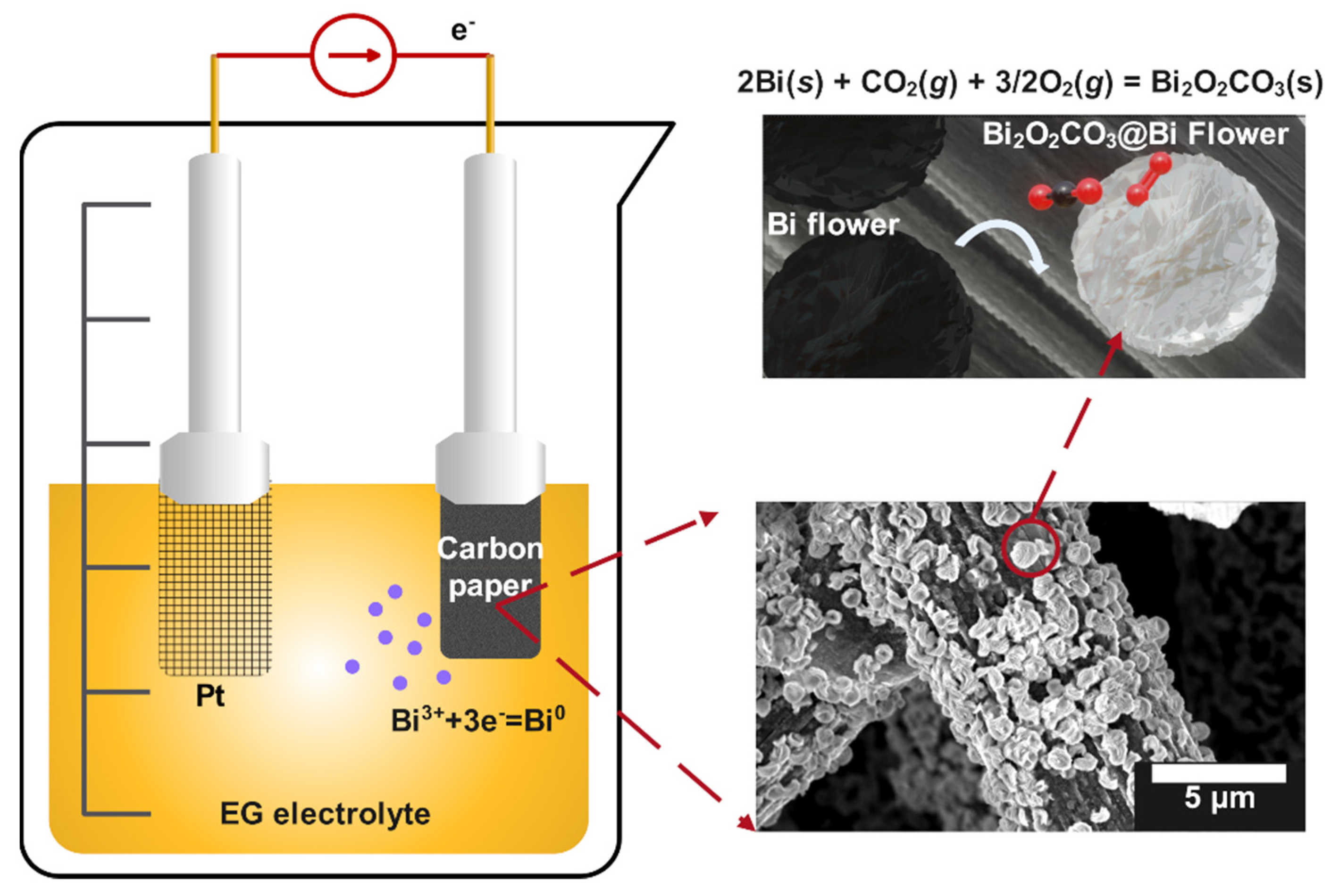
Scheme 1 reveals the electrodeposition reaction and surface conversion of flower-like bismuth into Bi2O2CO3. During the electrodeposition process, Bi3+ ions were reduced into Bi0 and underwent nucleation and continuous growth on the carbon fiber substrate to form a multilayer flower-like bismuth film after 60 min. The Bi2O2CO3 composite was generated slowly on the surface of the obtained Bi/CP sample after exposing it to air. Indeed, O2, H2O, or CO2 molecules adsorbed and interacted with the exposed Bi, and the oxide or hydroxide intermediate would be produced in the form of a thin layer [32,38]. As shown in Scheme 1, Bi2O2CO3 was eventually generated on the surface of the electrode after a series of physicochemical reactions. The in-situ conversion processes from Bi to Bi2O2CO3 are inferred as follows:
4Bi(s) + 3O2(g) + 2H2O(l) ⇌ 4BiO−(s) + 4OH−(aq)
CO2(g) + 2H2O(l) ⇌ HCO3−(aq) + H3O+(aq)
HCO3−(aq) + 2OH−(aq) + H3O+(aq) ⇌ CO32− (aq) + 3H2O(l)
2BiO−(s) + CO32− (aq) = Bi2O2CO3(s)

Scheme 1.
Schematic reaction mechanism of Bi3+ reduction and formation of flower-like Bi2O2CO3@Bi/CP.
First, the Bi nanosheet reacted with the absorbed O2 and formed a surface oxide layer as depicted in Equation (2). At the same time, the absorbed CO2 and H2O involved reactions that produced buffers on the Bi surface (Equations (3) and (4)). Finally, the oxidized Bi3+ layers combined with the buffer ions CO32− as shown in Equation (5). The total reaction could be described in Equation (6). CO2 and O2 absorbed onto the surface of the Bi nanosheets and then converted into Bi2O2CO3. Moreover, the unstable Bi(OH)3 intermediate would form and react with CO2 to transform into Bi2O2CO3 [32,51]. It is worth noting that the conversion of the nano Bi into Bi2O2CO3 was faster than the bulk Bi [33]. The nano size Bi is a very efficient material for capturing CO2 [33]. For the in-situ conversion, a large number of Bi–O bonds and grain boundaries formed and were exposed on the surface. Figure S1 shows the color of Bi/CP changed from black to silver, revealing the formation of Bi2O2CO3 after the drying treatment. In addition, the nano-structured Bi could transform into Bi2O2CO3 more easily than the dendrite bulk due to its reactive surface characteristics, which indicates the morphologies of Bi played a key role in the subsequent Bi2O2CO3 conversion processes.
Figure 1a,b displays the original carbon fiber with graining and the clusters of bismuth, which both appeared after electrodeposition, respectively. A multilayer flower-like bismuth with a diameter of about 1000 nm could be observed in Figure 1c. It can be explored that a longer deposition time led to the formation of a thicker Bi layer (Figure 1c,d) and a high current was inclined to form a Bi dendrite cluster with a large size, and thus covered the surface of the CP substrate (Figure S2). It should be noted that the electrodeposition time also has an impact on the morphology of the catalysts. Figure S3 showed the micrographs of an electrode under ~90 min deposition. A longer time of deposition led the nanosheets growing continuously, which further formed the multilayered Bi catalysts with obvious particle aggregation and damaged the flower-like structure. More details are shown in Figure S4, in which the flower-like Bi formed a thin layer on the surface of the carbon fiber uniformly. Compared to the nano-structured Bi generated at a low electrodeposition current density, the scree-structured Bi with a micro scale was obtained at a current density greater than 1.2 mA cm−2. The desired flower-like bismuth could be achieved at an appropriate current density range of 0.8 to 1 A cm−2.
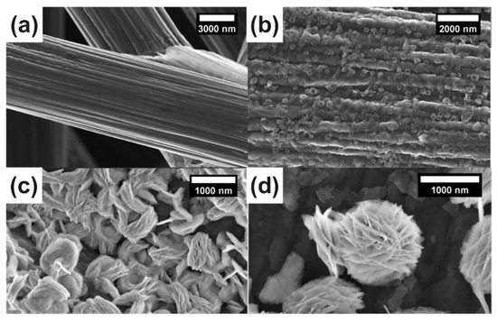
Figure 1.
SEM images (a–d) of Bi/CP at different electrodeposition times: (a) rough carbon fiber; (b) Bi/CP 20 min; (c) Bi/CP 40 min; (d) Bismuth flower features of Bi/CP 60 min.
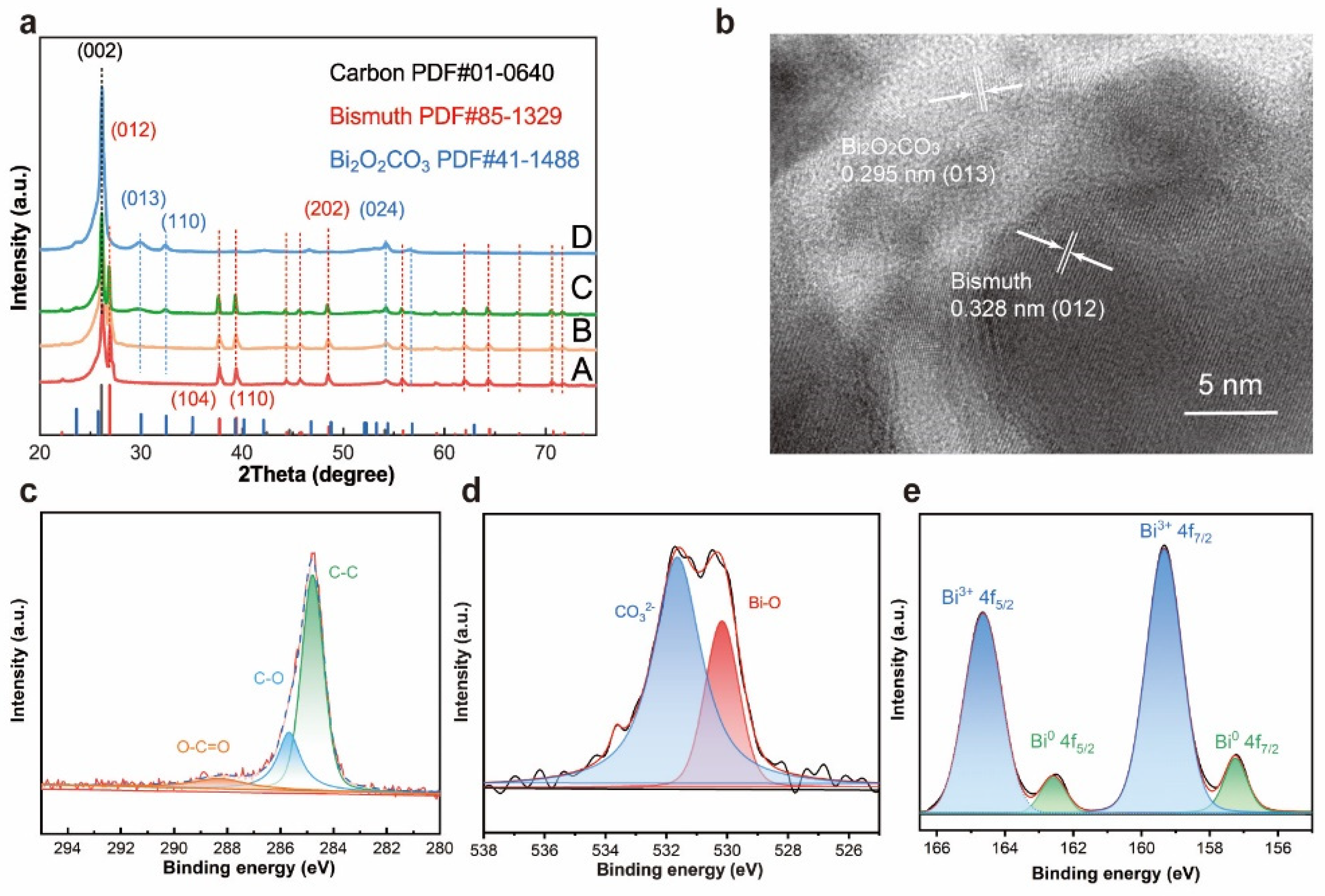
The morphology of Bi2O2CO3@Bi/CP was similar to the multilayer flower-like Bi. As shown in Figure S3 and S5, some fuzzy streaks can clearly be seen on the SEM images of Bi2O2CO3@/Bi/CP, which is attributed to the decrease in conductivity. The reduction in electrical conductivity could be ascribed to introducing Bi2O2CO3 into Bi/CP. X-ray diffraction (XRD) patterns are provided in Figure 2a to reveal the crystal types and changes of the samples. The (002) and (024) planes corresponding to graphite (JCPDS No. 01-0640) in all the samples are assigned to the CP. Furthermore, the crystalline structures of the as-prepared Bi/CP and Bi2O2CO3@Bi/CP achieved by exposing them to air are distinctly different. The peaks at 26.83, 37.65, 39.34, and 48.45° can be indexed to the (012), (104), (110), and (202) planes of the rhombohedral Bi (JCPDS No. 85-1329), respectively, and no other impurity peaks are observed. The intensive peak ~26.83°, which is attributed to the preferred orientation of the (012) plane, manifests the growth of flower-like Bi upon deposition. The spectrum of the sample exposed to the air presents the peaks at 23.83, 29.93, 32.40 and 45.22°, which corresponds to the (021), (023), (110) and (024) planes of Bi2O2CO3 (JCPDS No. 411488). In addition, Figure 2a shows that a wide weak peak appears in the XRD patterns of the Bi2O2CO3@Bi/CP, implying the composite has converted to an amorphous phase. It could be demonstrated that a partial flower-like Bi was converted into Bi2O2CO3 after exposing it to the air. According to previous studies, O2 and CO2 were freely chemi-absorbed on the bismuth surface in the air and led to the conversion reaction of Bi2O2CO3 [33]. To obtain further details on the delicate structure of the Bi2O2CO3@Bi/CP, a high-resolution TEM image (Figure 2b) is shown and proves that there is a fragment of the lattice and the interface of Bi and Bi2O2CO3. The apparent lattice fringes in Figure 2b are measured at ~0.295 and ~0.328 nm, corresponding to the (012) plane of Bi2O2CO3 and the (013) plane of Bi, respectively. Combined with the aforementioned SEM and XRD results, the existence of the transformed Bi2O2CO3 and primal Bi could be verified in the Bi2O2CO3@Bi/CP, implying the conversion process of the Bi nanosheets to Bi2O2CO3 on the interfaces.
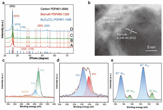
Figure 2.
Characterizations of Bi2O2CO3@Bi/CP samples. (a) XRD pattern of the synthesized Bi/CP in EG solution. Curve A: sample A electrodeposited at 1.2 mA by PC method, Curve B: sample B electrodeposited at 0.8 mA by PC method and put in an argon atmosphere, Curve C: sample C and D electrodeposited at 0.8 mA and exposed in air for three days and more than seven days, individually. (b) High resolution TEM images of Bi2O2CO3@Bi/CP. (c–e) X-ray photoelectron spectroscopy (XPS) spectra: (c) C1s, (d) O1s and (e) Bi 4f.
The surface chemical states of the Bi2O2CO3@Bi/CP were further investigated by XPS measurement. Figure 2c–e displays the high-resolution C 1s, O 1s, and Bi 4f spectrum, respectively, thereby confirming the formation of Bi2O3CO3. As shown in Figure 2c, three peaks at 284.79, 285.68, and 288.29 eV, which were attributed to the C–C, C–O, and O–C=O groups, respectively, are found in C1s spectrum, indicating the existence of CO32−. The O1s peak (Figure 2d) could be subdivided into two peaks of 530.17 and 531.46 eV, and were assigned to the Bi−O bond and CO32− species in Bi2O2CO3, respectively. Figure 2e shows two intensive symmetrical peaks located at 159.33 and 164.64 eV, implying the characteristic spin orbit splitting of the Bi3+ 4f peaks and corresponding to Bi3+ 4f7/2 and Bi3+ 4f5/2, respectively. Otherwise, two subordinate peaks at 157.24 and 162.59 eV are ascribed to the presence of Bi0. The XPS results are consistent with the above characterizations and further validate the surface transformation from nano-structured Bi to Bi2O2CO3 in air.
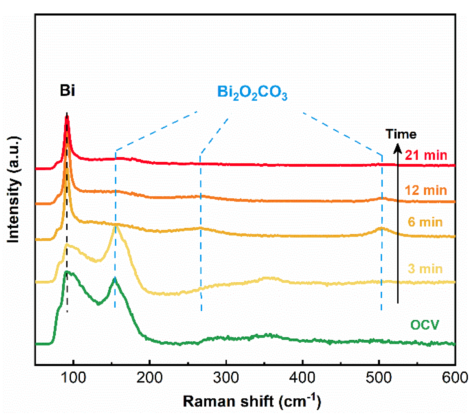
An in-situ Raman spectroscopy study was performed to explore the surface transformation mechanism of the Bi2O2CO3@Bi/CP electrode. The measurement was carried out through an electrochemical reduction procedure at −0.9 V vs. RHE in the CO2 saturated 0.5 M KHCO3 electrolyte. The Raman spectra (Figure 3) indicate the peaks at 92 cm−1 are related to the Bi–Bi bond that appeared at the beginning. The intensity of the peak at 154 cm−1 (belonged to the Bi–O bond) decreased and almost disappeared after a six min reduction, which is attributed to the reduction of surface Bi2O2CO3 into Bi. The broad external vibration peak at 264.05 cm−1 [26,40], as well as a weak peak around 502.94 cm−1 attributed to the Bi=O bond, are assigned to Bi2O2CO3 [52], which did not vanish even after a continuous reduction process (Figure S6). In this study, flower-like Bi nanosheets could provide plenty of reaction sites to regenerate Bi2O2CO3 on its surface in a CO2 rich environment and the composite would not reduce, even in a relative negative potential (~−0.90 V vs. RHE) during the heterogeneous electrocatalysis process.
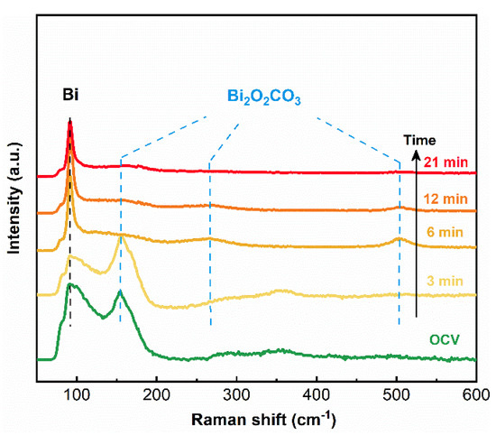
Figure 3.
In-situ Raman spectra of Bi2O2CO3@Bi/CP during the electrochemical reduction of CO2 at −0.90 V vs. RHE in the CO2 saturated 0.50 M KHCO3 electrolyte.
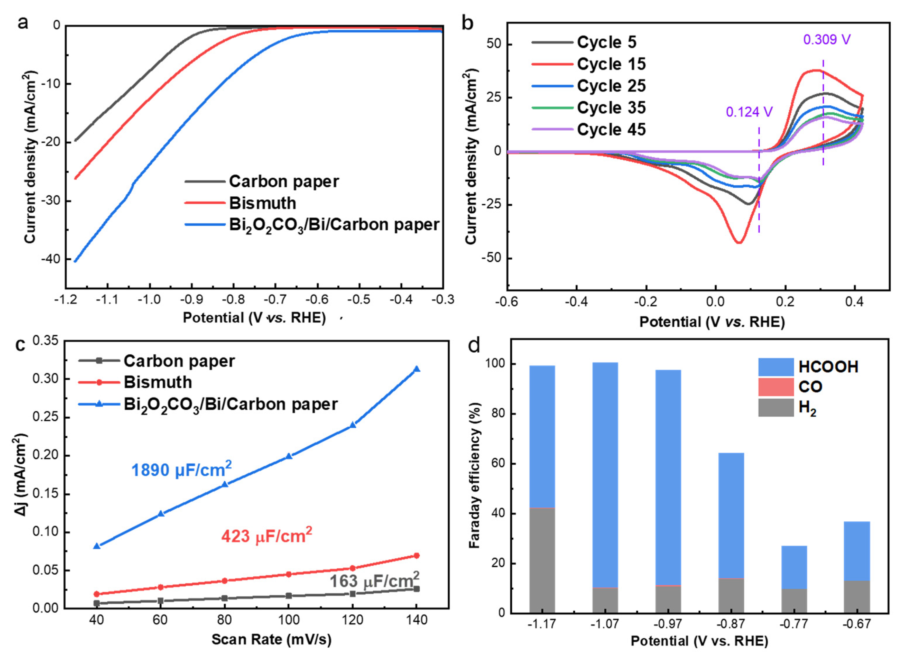
To study the electrochemical CO2RR performance of the obtained catalysts, linear sweep voltammetry (LSV) measurements were conducted from −0.3 to −1.2 V vs. RHE in the CO2 saturated 0.50 M KHCO3 electrolyte. As shown in Figure 4a, the CO2RR Faradaic onset potential is observed at −0.56 and −0.76 V vs. RHE for the Bi2O2CO3@Bi/CP and the Bi/CP electrode in the CO2 saturated 0.50 M KHCO3 electrolyte, respectively. In addition, the onset potential of HER on carbon paper is −0.84 V vs. RHE. The lower onset potential of Bi2O2CO3@Bi/CP manifests a higher CO2 reduction activity, indicating that introducing Bi2O2CO3 into Bi-based catalysts is favorable to CO2RR. The total current density (Jtot) of the Bi2O2CO3@Bi/CP electrode is ~20 mA cm−2 at −1.07 V vs. RHE, which is much higher than those in the N2− saturated condition and sufficiently demonstrates the CO2RR activity (Figure S7). The cyclic voltammetry curves in Figure 4b and S8 exhibit an oxidation peak at ~0.31 V and a reduction peak at ~0.12 V, which can be attributed to the Bi3+/Bi0 redox process in the Bi2O2CO3@Bi/CP electrode, and another reduction peak at a more negative potential (−0.90 V) is assigned to the electrochemical CO2 reduction or competitive H2 evolution. The as-prepared Bi2O2CO3@Bi/CP electrode revealed a high interface resistance, leading to a relatively low current density during the initial CV cycles. After several redox cycles, the adsorbed impurities, such as inert gas on the surface of the electrode, have been removed and the catalytic interface became dynamically stable, and thus the CV current density reached the maximum. After that, the Bi2O2CO3 composite in the electrode gradually reduced during the negative potential and the current density decreased. The redox peaks still remained after 50 cycles, which indicates the stability of the Bi2O2CO3@Bi interfaces and is in accordance with the previous reports [53,54]. Meanwhile, an observable positive shift in the reduction peak was recorded on the CVs curves, which was attributed to the conversion of Bi–O or Bi=O to Bi–Bi bonds [47].
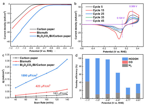
Figure 4.
(a) LSV curves of Carbon paper, Bi electrodeposited at 1.6 mA (0.8 mA cm−2) and Bi2O2CO3@Bi/CP; (b) CV curves of Bi2O2CO3@Bi/CP in CO2-saturated 0.50 M KHCO3 electrolyte; (c) Charging current density differences plotted against scan rates; (d) FE of CO2RR products at various potentials on Bi2O2CO3@Bi/CP in CO2-saturated 0.50 M KHCO3 electrolyte.
The electrochemical surface area (ECSA) of the electrodes was evaluated by CV measurements at a potential range from 0 to −0.2 V vs. RHE with a variety of scanning rates (Figure S9). As shown in Figure 4c, the current densities of the electrodes are proportional to the scanning rates and the Bi2O2CO3@Bi/CP (1890 µFcm−2) delivers a four times greater double layer capacitance than the Bi/CP (423 µF cm−2). The higher ECSA of the Bi2O2CO3@ Bi/CP confirms the electrode could provide more catalytic active sites, which could benefit the CO2RR performance.
To practically evaluate the catalytic performance of the Bi2O2CO3@Bi/CP electrode, we performed CO2RR tests in a three-electrode flow-cell reactor (Figure S10). The Bi2O2CO3@Bi/CP and IrO2/CP were employed as the work and counter electrode, respectively. More details can be found in the Supplementary Data. Figure 4d shows the product distribution ratio results obtained at a wide potential ranging (−0.67 to −1.17 V). The highest FE of HCOOH (~82%) was reached on the Bi/CP electrode at −0.89 V vs. RHE as shown in Figure S11, and the Bi2O2CO3@Bi/CP electrode conveyed a maximum FEHCOOH of 89%, which was achieved at −1.07 V vs. RHE. The enhancement of the CO2RR performance by introducing Bi2O2CO3 into the Bi/CP electrode could be attributed to the large amounts of Bi–O bonds and grain boundaries, which lowers the energy barrier for the formation of the CO2− intermediate and promotes the production of formate [39,40]. The residual Bi2O2CO3 in the catalyst was expected to form a surface environment to improve the CO2 adsorption process and is of great benefit to CO2 reduction activation.
In addition, to evaluate the long-term durability of the Bi2O2CO3@Bi/CP electrode, the CO2RR tests were performed at −1.07 V vs. RHE in the same flow-cell reactor. As shown in Figure 5a,b, a constant current density is achieved at ~18.6 mA cm−2 with no remarkable decline, and the FEHCOOH value is found to be basically consistent with the former result and within the range of 84–89% during a 10 h continuous test. As a result, the Bi2O2CO3@Bi/CP electrode exhibits outstanding stability and high selectivity in a practical CO2 catalytic measurement.
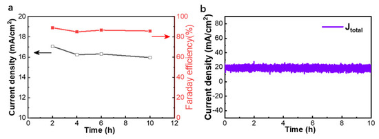
Figure 5.
Stability test of the Bi2O2CO3@Bi/CP electrode evaluated at −1.07 V vs. RHE in a CO2 saturated 0.5 M KHCO3 electrolyte by a flow-cell reactor. (a) partial current densities of HCOOH (jHCOOH) and FE during the test; (b) the real-time current density of the test.
4. Conclusions
In summary, a flower-like Bi nanosheet was fabricated by pulse current electrodeposition, and the morphologies could be accurately and facilely controlled by the current density. The achieved flower-like Bi nanosheets could form stable Bi2O2CO3@Bi interfaces after being exposed to air, which was also confirmed by the in-situ Raman spectroscopy. The Bi2O2CO3@Bi interfaces exhibited an improved CO2 reduction activity than the bulk Bi electrode. The electrochemical test demonstrated that the Bi2O2CO3@Bi/CP electrode conveyed an excellent FEHCOOH of 89% at −1.07 V vs. RHE with a current density of ~16 mA cm−2 in a flow-cell reactor. In addition, the catalyst showed an outstanding stability and no obvious degradation after a continuous test of over 10 h. This composite catalyst supports a rational strategy for designing Bi-based CO2RR catalysts and can also be applied to various electrochemical energy conversion and storage fields.
Supplementary Materials
The following supporting information can be downloaded at: https://www.mdpi.com/article/10.3390/coatings12020233/s1, Figure S1. The sample photo of original carbon paper, dendrite Bi/CP, and Bi2O2CO3@Bi/CP. Figure S2. SEM images of samples on different pulse current: (a) 0.4 mA cm−2, (b) 0.8 mA cm−2, (c) 1.2 mA cm−2, and (d) 1.6 mA cm−2. Figure S3. SEM image of electrode at 90 min electrodeposition with a current density of 0.8 mA cm−2. Figure S4. SEM photographs at different magnifications. Figure S5. SEM characterizations of a flower-like Bi sample exposed in air for a long time (>60 h). Figure S6. The particular Raman spectra of Bi2O2CO3@Bi/CP: (a) the Bi–Bi bond peak and Bi–O bond peak; (b) the broad external vibration peaks on Bi2O2CO3; and (c) the Bi=O bond peak. Figure S7. LSV curves of Carbon paper, Bi/CP, and Bi2O2CO3@Bi/CP in the N2 saturated 0.5 M KHCO3. Figure S8. The typical CV curve of a pristine Bi2O2CO3@Bi/CP at scanning rate of 20 mV s-1 from −1.2 to 0.4 V vs. RHE. Figure S9. CV curves of different samples: (a) the CV curves result of original carbon paper; (b) the CV curves test of Bi/CP; (c) the CV curves of Bi2O2CO3@Bi/CP. Figure S10. A flow cell rector for CO2RR with auxiliary equipment, including peristaltic pump, mass flow meter, resource gas, and electrochemical station. Figure S11. FE of CO2RR products at various potentials in CO2-saturated 0.5 M KHCO3 electrolytes on Bi/CP.
Author Contributions
S.L.: conceptualization, methodology, writing—original draft preparation; B.H.: writing—review and editing; C.Z.: conceptualization, methodology, writing—review and editing, supervision, project administration; J.Z. and D.F.: visualization; W.J.: writing—review and editing and funding acquisition; W.Y.: conceptualization, supervision, project administration and funding acquisition. All authors have read and agreed to the published version of the manuscript.
Funding
This work was supported by the National Key Research and Development Program of China (2020YFA0710304), National Natural Science Foundation of China (21805304 and 22002185), Civil Aerospace Technology Research Project (B0108) and the independent innovation project of Qian Xuesen Laboratory of Space Technology.
Institutional Review Board Statement
Not applicable.
Informed Consent Statement
Not applicable.
Data Availability Statement
Not applicable.
Conflicts of Interest
The authors declare no conflict of interest.
References
- Nguyen, T.N.; Dinh, C.T. Gas diffusion electrode design for electrochemical carbon dioxide reduction. Chem. Soc. Rev. 2020, 49, 7488–7504. [Google Scholar] [CrossRef] [PubMed]
- Wang, F.; Harindintwali, J.D.; Yuan, Z.; Wang, M.; Li, S.; Yin, Z.; Huang, L.; Fu, Y.; Li, L.; Chang, S.X.; et al. Technologies and perspectives for achieving carbon neutrality. Innovation 2021, 2, 100180. [Google Scholar] [CrossRef] [PubMed]
- Yang, L.; Zhang, C.; Yu, X.; Yao, Y.; Li, Z.; Wu, C.; Yao, W.; Zou, Z. Extraterrestrial artificial photosynthetic materials for in-situ resource utilization. Natl. Sci. Rev. 2021, 8, nwab104. [Google Scholar] [CrossRef] [PubMed]
- Deng, W.; Yuan, T.; Chen, S.; Li, H.; Hu, C.; Dong, H.; Wu, B.; Wang, T.; Li, J.; Ozin, G.A.; et al. Effect of bicarbonate on CO2 electroreduction over cathode catalysts. Fundam. Res. 2021, 1, 432–438. [Google Scholar] [CrossRef]
- Löwe, A.; Schmidt, M.; Bienen, F.; Kopljar, D.; Wagner, N.; Klemm, E. Optimizing Reaction Conditions and Gas Diffusion Electrodes Applied in the CO2 Reduction Reaction to Formate to Reach Current Densities up to 1.8 A cm–2. ACS Sustain. Chem. Eng. 2021, 9, 4213–4223. [Google Scholar] [CrossRef]
- Tan, X.; Yu, C.; Ren, Y.; Cui, S.; Li, W.; Qiu, J. Recent advances in innovative strategies for the CO2 electroreduction reaction. Energy Environ. Sci. 2021, 14, 765–780. [Google Scholar] [CrossRef]
- Claassens, N.J.; Cotton, C.A.R.; Kopljar, D.; Bar-Even, A. Making quantitative sense of electromicrobial production. Nat. Catal. 2019, 2, 437–447. [Google Scholar] [CrossRef]
- Pribyl-Kranewitter, B.; Beard, A.; Gîjiu, C.; Dinculescu, D.; Schmidt, T. Influence of low-temperature electrolyser design on economic and environmental potential of CO and HCOOH production: A techno-economic assessment. Renew. Sustain. Energy Rev. 2021, 154, 111807. [Google Scholar] [CrossRef]
- Oh, W.; Rhee, C.K.; Han, J.W.; Shong, B. Atomic and Molecular Adsorption on the Bi(111) Surface: Insights into Catalytic CO2 Reduction. J. Phys. Chem. C 2018, 122, 23084–23090. [Google Scholar] [CrossRef]
- Duan, Y.X.; Zhou, Y.T.; Yu, Z.; Liu, D.X.; Wen, Z.; Yan, J.M.; Jiang, Q. Boosting production of HCOOH from CO2 electroreduction via Bi/CeOx. Angew. Chem. Int. Ed. Engl. 2021, 133, 8880–8884. [Google Scholar] [CrossRef]
- Suominen, M.; Kallio, T. What We Currently Know about Carbon-Supported Metal and Metal Oxide Nanomaterials in Electrochemical CO2 Reduction. ChemElectroChem 2021, 8, 2397–2406. [Google Scholar] [CrossRef]
- Han, N.; Ding, P.; He, L.; Li, Y.; Li, Y. Promises of Main Group Metal–Based Nanostructured Materials for Electrochemical CO2 Reduction to Formate. Adv. Energy Mater. 2020, 10, 1902338. [Google Scholar] [CrossRef]
- Hara, K.; Kudo, A.; Sakata, T. Electrochemical reduction of carbon dioxide under high pressure on various electrodes in an aqueous electrolyte. J. Electroanal. Chem. 1995, 391, 141–147. [Google Scholar] [CrossRef]
- Han, N.; Wang, Y.; Yang, H.; Deng, J.; Wu, J.; Li, Y.; Li, Y. Ultrathin bismuth nanosheets from in situ topotactic transformation for selective electrocatalytic CO2 reduction to formate. Nat. Commun. 2018, 9, 1320. [Google Scholar] [CrossRef]
- Fan, M.; Prabhudev, S.; Garbarino, S.; Qiao, J.; Botton, G.A.; Harrington, D.; Tavares, A.C.; Guay, D. Uncovering the nature of electroactive sites in nano architectured dendritic Bi for highly efficient CO2 electroreduction to formate. Appl. Catal. B Environ. 2020, 274, 119031. [Google Scholar] [CrossRef]
- Guan, Y.; Liu, M.; Rao, X.; Liu, Y.; Zhang, J. Electrochemical reduction of carbon dioxide (CO2): Bismuth-based electrocatalysts. J. Mater. Chem. A 2021, 9, 13770–13803. [Google Scholar] [CrossRef]
- Fan, T.; Ma, W.; Xie, M.; Liu, H.; Zhang, J.; Yang, S.; Huang, P.; Dong, Y.; Chen, Z.; Yi, X. Achieving high current density for electrocatalytic reduction of CO2 to formate on bismuth-based catalysts. Cell Rep. Phys. Sci. 2021, 2, 100353. [Google Scholar] [CrossRef]
- Al-Tamreh, S.A.; Ibrahim, M.H.; El-Naas, M.H.; Vaes, J.; Pant, D.; Benamor, A.; Amhamed, A. Electroreduction of Carbon Dioxide into Formate: A Comprehensive Review. ChemElectroChem 2021, 8, 3207–3220. [Google Scholar] [CrossRef]
- Zhang, H.; Ma, Y.; Quan, F.; Huang, J.; Jia, F.; Zhang, L. Selective electro-reduction of CO2 to formate on nanostructured Bi from reduction of BiOCl nanosheets. Electrochem. Commun. 2014, 46, 63–66. [Google Scholar] [CrossRef]
- Lee, C.W.; Hong, J.S.; Yang, K.D.; Jin, K.; Lee, J.H.; Ahn, H.-Y.; Seo, H.; Sung, N.-E.; Nam, K.T. Selective Electrochemical Production of Formate from Carbon Dioxide with Bismuth-Based Catalysts in an Aqueous Electrolyte. ACS Catal. 2018, 8, 931–937. [Google Scholar] [CrossRef]
- Gomez, C.; Hallot, G.; Pastor, A.; Laurent, S.; Brun, E.; Sicard-Roselli, C.; Port, M. Metallic bismuth nanoparticles: Towards a robust, productive and ultrasound assisted synthesis from batch to flow-continuous chemistry. Ultrason. Sonochemistry 2019, 56, 167–173. [Google Scholar] [CrossRef]
- Zhang, D.; Tao, Z.; Feng, F.; He, B.; Zhou, W.; Sun, J.; Xu, J.; Wang, Q.; Zhao, L. High efficiency and selectivity from synergy: Bi nanoparticles embedded in nitrogen doped porous carbon for electrochemical reduction of CO2 to formate. Electrochim Acta 2020, 334, 135563. [Google Scholar] [CrossRef]
- Wang, D.; Chang, K.; Zhang, Y.; Wang, Y.; Liu, Q.; Wang, Z.; Ding, D.; Cui, Y.; Pan, C.; Lou, Y.; et al. Unravelling the electrocatalytic activity of bismuth nanosheets towards carbon dioxide reduction: Edge plane versus basal plane. Appl. Catal. B Environ. 2021, 299, 120693. [Google Scholar] [CrossRef]
- Kuang, Z.; Peng, C.; Li, C.; Yao, H.; Zhou, X.; Chen, H. Efficient electrocatalytic CO2 conversion into formate with AlxBiyOz nanorods in a wide potential window. Catal. Sci. Technol. 2021, 11, 7704–7711. [Google Scholar] [CrossRef]
- Zhong, H.; Qiu, Y.; Zhang, T.; Li, X.; Zhang, H.; Chen, X. Bismuth nanodendrites as a high performance electrocatalyst for selective conversion of CO2 to formate. J. Mater. Chem. A 2016, 4, 13746–13753. [Google Scholar] [CrossRef]
- Fan, K.; Jia, Y.; Ji, Y.; Kuang, P.; Zhu, B.; Liu, X.; Yu, J. Curved Surface Boosts Electrochemical CO2 Reduction to Formate via Bismuth Nanotubes in a Wide Potential Window. ACS Catal. 2020, 10, 358–364. [Google Scholar] [CrossRef]
- Gong, Q.; Ding, P.; Xu, M.; Zhu, X.; Wang, M.; Deng, J.; Ma, Q.; Han, N.; Zhu, Y.; Lu, J.; et al. Structural defects on converted bismuth oxide nanotubes enable highly active electrocatalysis of carbon dioxide reduction. Nat. Commun. 2019, 10, 2807. [Google Scholar] [CrossRef] [Green Version]
- Zhang, X.; Lei, T.; Liu, Y.; Qiao, J. Enhancing CO2 electrolysis to formate on facilely synthesized Bi catalysts at low overpotential. Appl. Catal. B Environ. 2017, 218, 46–50. [Google Scholar] [CrossRef]
- Sui, P.F.; Xu, C.; Zhu, M.N.; Liu, S.; Liu, Q.; Luo, J.L. Interface-Induced Electrocatalytic Enhancement of CO2 -to-Formate Conversion on Heterostructured Bismuth-Based Catalysts. Small 2022, 18, e2105682. [Google Scholar] [CrossRef]
- Gao, T.; Wen, X.; Xie, T.; Han, N.; Sun, K.; Han, L.; Wang, H.; Zhang, Y.; Kuang, Y.; Sun, X. Morphology effects of bismuth catalysts on electroreduction of carbon dioxide into formate. Electrochim. Acta 2019, 305, 388–393. [Google Scholar] [CrossRef]
- Kim, S.; Dong, W.J.; Gim, S.; Sohn, W.; Park, J.Y.; Yoo, C.J.; Jang, H.W.; Lee, J.-L. Shape-controlled bismuth nanoflakes as highly selective catalysts for electrochemical carbon dioxide reduction to formate. Nano Energy 2017, 39, 44–52. [Google Scholar] [CrossRef]
- An, X.; Li, S.; Hao, X.; Du, X.; Yu, T.; Wang, Z.; Hao, X.; Abudula, A.; Guan, G. The In Situ morphology transformation of bismuth-based catalysts for the effective electroreduction of carbon dioxide. Sustain. Energy Fuels 2020, 4, 2831–2840. [Google Scholar] [CrossRef]
- Ortiz-Quiñonez, J.L.; Vega-Verduga, C.; Díaz, D.; Zumeta-Dubé, I. Transformation of Bismuth and β-Bi2O3 Nanoparticles into (BiO)2CO3 and (BiO)4(OH)2CO3 by Capturing CO2: The Role of Halloysite Nanotubes and “Sunlight” on the Crystal Shape and Size. Cryst. Growth Des. 2018, 18, 4334–4346. [Google Scholar] [CrossRef]
- Zhang, J.; Liu, Z.; Ma, Z. Facile Formation of Bi2O2CO3/Bi2MoO6 Nanosheets for Visible Light-Driven Photocatalysis. ACS Omega 2019, 4, 3871–3880. [Google Scholar] [CrossRef] [Green Version]
- Lv, W.; Bei, J.; Zhang, R.; Wang, W.; Kong, F.; Wang, L.; Wang, W. Bi2O2CO3 Nanosheets as Electrocatalysts for Selective Reduction of CO2 to Formate at Low Overpotential. ACS Omega 2017, 2, 2561–2567. [Google Scholar] [CrossRef] [Green Version]
- Liu, S.-Q.; Shahini, E.; Gao, M.-R.; Gong, L.; Sui, P.-F.; Tang, T.; Zeng, H.; Luo, J.-L. Bi2O3 Nanosheets Grown on Carbon Nanofiber with Inherent Hydrophobicity for High-Performance CO2 Electroreduction in a Wide Potential Window. ACS Nano 2021, 15, 17757–17768. [Google Scholar] [CrossRef]
- Deng, P.; Wang, H.; Qi, R.; Zhu, J.; Chen, S.; Yang, F.; Zhou, L.; Qi, K.; Liu, H.; Xia, B.Y. Bismuth Oxides with Enhanced Bismuth–Oxygen Structure for Efficient Electrochemical Reduction of Carbon Dioxide to Formate. ACS Catal. 2019, 10, 743–750. [Google Scholar] [CrossRef]
- Wang, Y.; Wang, B.; Jiang, W.; Liu, Z.; Zhang, J.; Gao, L.; Yao, W. Sub-2 nm ultra-thin Bi2O2CO3 nanosheets with abundant Bi-O structures toward formic acid electrosynthesis over a wide potential window. Nano Res. 2021, 1–9. [Google Scholar] [CrossRef]
- Zhou, Y.; Yan, P.; Jia, J.; Zhang, S.; Zheng, X.; Zhang, L.; Zhang, B.; Chen, J.; Hao, W.; Chen, G.; et al. Supercritical CO2-constructed intralayer [Bi2O2]2+ structural distortion for enhanced CO2 electroreduction. J. Mater. Chem. A Mater. 2020, 8, 13320–13327. [Google Scholar] [CrossRef]
- Dutta, A.; Montiel, I.Z.; Kiran, K.; Rieder, A.; Grozovski, V.; Gut, L.; Broekmann, P. A Tandem (Bi2O3 → Bimet) Catalyst for Highly Efficient ec-CO2 Conversion into Formate: Operando Raman Spectroscopic Evidence for a Reaction Pathway Change. ACS Catal. 2021, 11, 4988–5003. [Google Scholar] [CrossRef]
- Li, L.; Ma, D.-K.; Qi, F.; Chen, W.; Huang, S. Bi nanoparticles/Bi2O3 nanosheets with abundant grain boundaries for efficient electrocatalytic CO2 reduction. Electrochim. Acta 2019, 298, 580–586. [Google Scholar] [CrossRef]
- Bertin, E.; Garbarino, S.; Roy, C.; Kazemi, S.; Guay, D. Selective electroreduction of CO2 to formate on Bi and oxide-derived Bi films. J. CO2 Util. 2017, 19, 276–283. [Google Scholar] [CrossRef]
- Liu, S.; Lu, X.F.; Xiao, J.; Wang, X.; Lou, X.W. (David) Bi2O3 Nanosheets Grown on Multi-Channel Carbon Matrix to Catalyze Efficient CO2 Electroreduction to HCOOH. Angew. Chem. 2019, 131, 13966–13971. [Google Scholar] [CrossRef]
- Zhang, Y.; Zhang, X.; Ling, Y.; Li, F.; Bond, A.M.; Zhang, J. Controllable Synthesis of Few-Layer Bismuth Subcarbonate by Electrochemical Exfoliation for Enhanced CO2 Reduction Performance. Angew. Chem. Int. Ed. 2018, 57, 13283–13287. [Google Scholar] [CrossRef]
- Zhao, M.; Gu, Y.; Gao, W.; Cui, P.; Tang, H.; Wei, X.; Zhu, H.; Li, G.; Yan, S.; Zhang, X.; et al. Atom vacancies induced electron-rich surface of ultrathin Bi nanosheet for efficient electrochemical CO2 reduction. Appl. Catal. B Environ. 2020, 266, 118625. [Google Scholar] [CrossRef]
- Wang, J.; Mao, J.; Zheng, X.; Zhou, Y.; Xu, Q. Sulfur boosting CO2 reduction activity of bismuth subcarbonate nanosheets via promoting proton-coupled electron transfer. Appl. Surf. Sci. 2021, 562, 150197. [Google Scholar] [CrossRef]
- Puppin, L.G.; Khalid, M.; da Silva, G.T.T.; Ribeiro, C.; Varela, H.; Lopes, O.F. Electrochemical reduction of CO2 to formic acid on Bi2O2CO3/carbon fiber electrodes. J. Mater. Res. 2020, 35, 272–280. [Google Scholar] [CrossRef]
- Ramler, J.; Lichtenberg, C. Molecular Bismuth Cations: Assessment of Soft Lewis Acidity. Chem.—A Eur. J. 2020, 26, 10250–10258. [Google Scholar] [CrossRef]
- Ramler, J.; Wüst, L.; Rempel, A.; Wolz, L.; Lichtenberg, C. Bismuth Atoms in Hydrocarbon Ligands: Bismepines as Rigid, Ditopic Arene Donors in Coordination Chemistry. Organometallics 2021, 40, 832–837. [Google Scholar] [CrossRef]
- Yan, T.; Li, N.; Wang, L.; Ran, W.; Duchesne, P.N.; Wan, L.; Nguyen, N.T.; Wang, L.; Xia, M.; Ozin, G.A. Bismuth atom tailoring of indium oxide surface frustrated Lewis pairs boosts heterogeneous CO2 photocatalytic hydrogenation. Nat. Commun. 2020, 11, 6095. [Google Scholar] [CrossRef]
- Rayner-Canham, G.; Overton, T. Descriptive Inorganic Chemistry, 4th ed.; W. H. Freeman Basingstoke; Palgrave Macmillan: New York, NY, USA, 2006. [Google Scholar]
- Tobon- Zapata, G.E.; Etcheverry, S.B.; Baran, E.J. Vibrational spectrum of bismuth subcarbonate. J. Mater. Sci. Lett. 1997, 16, 656–657. [Google Scholar] [CrossRef]
- Zhang, Y.; Li, F.; Zhang, X.; Williams, T.; Easton, C.D.; Bond, A.M.; Zhang, J. Electrochemical reduction of CO2 on defect-rich Bi derived from Bi2S3with enhanced formate selectivity. J. Mater. Chem. A 2018, 6, 4714–4720. [Google Scholar] [CrossRef]
- Rajamani, A.R.; Jothi, S.; Kumar, M.D.; Srikaanth, S.; Singh, M.K.; Otero-Irurueta, G.; Ramasamy, D.; Datta, M.; Rangarajan, M. Effects of Additives on Kinetics, Morphologies and Lead-Sensing Property of Electrodeposited Bismuth Films. J. Phys. Chem. C 2016, 120, 22398–22406. [Google Scholar] [CrossRef] [Green Version]


Publisher’s Note: MDPI stays neutral with regard to jurisdictional claims in published maps and institutional affiliations. |
© 2022 by the authors. Licensee MDPI, Basel, Switzerland. This article is an open access article distributed under the terms and conditions of the Creative Commons Attribution (CC BY) license (https://creativecommons.org/licenses/by/4.0/).