Article

Titanium Oxide Coatings Deposited on MnZn Ferrite by a Molten Salt Reaction

1
Shanghai Institute of Applied Physics, Chinese Academy of Sciences, Shanghai 201800, China
2
University of Chinese Academy of Sciences, Beijing 100049, China
*
Authors to whom correspondence should be addressed.
Coatings 2022, 12(3), 298; https://doi.org/10.3390/coatings12030298
Submission received: 14 January 2022 / Revised: 12 February 2022 / Accepted: 17 February 2022 / Published: 23 February 2022
(This article belongs to the Topic Inorganic Thin Film Materials)

Abstract

:
Using molten salt reactions, Ti oxide coatings were successfully deposited on MnZn ferrite in a NaCl–KCl–K2TiF6 melt. The film formed on the surface of MnZn ferrite had a thickness of up to 20 μm and was composed of Ti oxides. The electric conductivity of the coatings was contributed to by the component Ti2O3 and depended on the concentration of Ti2O3 in the film. When the Ti2O3 content in the film increased, the surface resistance dropped to the order of 10−1 Ω/□. The conductive film had the potential to be welded to the metal electrode, thus confirming that the molten salt reaction method could be used as a pre-treatment to realize the metallization of MnZn ferrite.

1. Introduction

MnZn ferrite is one of the most common soft magnetic ferrites and has a wide range of technological applications. It has a spinel structure and is composed of MnO, ZnO and Fe2O3. MnZn ferrites are preferred in the class of soft magnetic ferrites due to their high permeability, high impedance, high saturation magnetic induction, low power loss, low coercivity and other unique properties [1,2]. Therefore, these materials are used to make filters, waveguides and magnetic cores, which are widely used in communication and electronic information technology [3,4]. With wireless communication technology entering the 5G era, the construction of a 5G “new infrastructure” puts forward higher requests and more requirements for microwave ferrites, especially MnZn ferrite [5,6,7].
When MnZn ferrite is used in electronic components, in order to strengthen its adhesion to metal electrodes, surface modification is required [8,9]. In addition, when MnZn ferrite is used in microwave devices, the surface of the ferrite also needs to be modified in order to make the electromagnetic wave propagate inside the device and avoid the loss of the electromagnetic wave [10,11,12]. Ceramic surface plating refers to the coating of a conductive layer that is firmly bonded and not easy to melt on the ceramic surface. At present, there are several methods of ceramic material surface plating such as electroless plating [13,14], electrodeposition [15] and magnetron sputtering [16,17]. Up to date, the main methods of plating a ferrite surface are magnetron sputtering and silver coating. However, these two methods have the problems of a complex operation, high production cost, difficulty in the mass production of devices and an insufficient bonding force.
On the other hand, a molten salt reaction is a method that uses one or more salts with a low melting point as a reaction medium to form thin films on the surface of materials through a disproportionation reaction [18,19,20]. The molten salt reaction method has several unique characteristics—for instance, there are no special requirements for the surface roughness of the substrate material—and the bonding between the film and the substrate is firm [21]. However, as far as we know, an experimental study on the surface plating of MnZn ferrite, a multicomponent composite oxide ceramic, by a molten salt reaction has not been reported.
In this paper, a titanium modification on the surface of MnZn ferrite was studied by the molten salt reaction method. The morphology, thickness and phase of the film were observed by scanning electron microscopy (SEM) and X-ray diffraction (XRD) and the morphology and structure of the film particles were observed by transmission electron microscopy (TEM). The conductivity of the film formed on the surface of MnZn ferrite was measured by a four-point probe low resistance tester; finally, the mechanism of the film growth was further explored.

2. Experiment

MnZn ferrite (70.56 wt% Fe2O3, 13.18 wt% ZnO, 16.26 wt% MnO) samples with dimensions of 50 mm × 50 mm × 1 mm supplied by KingStar Electronics Technology Co., Ltd. (Guangdong, China) were used in the experiment. Before the treatment, the samples were first polished with 1000 mesh metallographic sandpaper and then were cleaned in an ultrasonic cleaner with water and alcohol in turn. A mixture of equimolar NaCl–KCl was chosen as the molten salt solvent; 5 wt% K2TiF6 was added as the Ti4+ source and 5 wt% Ti powder was added as the Ti source [22]. The salts were mixed and put into a crucible in a glove box and then heated to the reaction temperature of 850 °C. The MnZn ferrite samples were placed above the molten salt in the crucible and preheated for 10 min in order to avoid fragmentation and were then immersed into the molten salts for 1, 2, 3, 5, 10 and 20 min, respectively. The schematic diagram of the experimental setup is shown in Figure 1.
The whole process was undertaken in a glove box filled with argon and the oxygen and moisture in the glove box were kept below 1 ppm. After cooling to room temperature in the glove box, the coated samples were taken out and successively washed with water and then alcohol to remove the residual salt. Finally, the samples were dried and prepared for characterization. For the TEM observation, powder samples were prepared by scraping the coated ferrite surface with a diamond knife. The powder was cleaned in an ultrasonic cleaner with alcohol, taken out with a pipette and prepared as TEM samples through microgrid filtration.
The surface and cross-section morphologies of the samples were observed by SEM (LEO 1530VP, Oberkohen, Germany). The material compositions were determined by XRD (D8 Advance, Brooke, Germany) with Ni foil-filtered Cu Kα radiation at a working voltage of 40 kV and a current of 40 mA. The morphology and structural changes of the film particles were observed by TEM (Tecnai G2 F20 S–TWIN, Hillsborough, OR, USA). The surface sheet resistance of the coated MnZn ferrite was tested using a four-point probe low resistance tester (SMT–SR1000N, Shenzhen, China).

3. Results

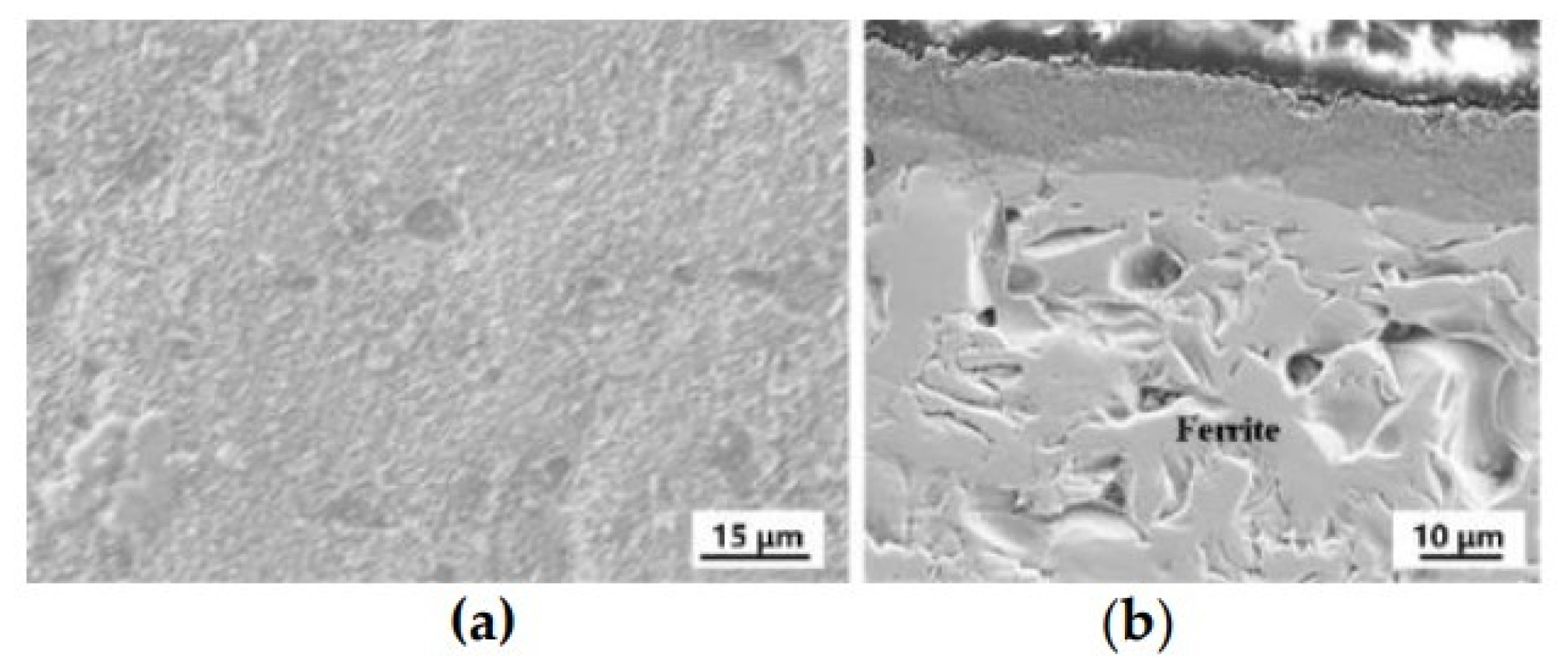
The surface of MnZn ferrite was rough and showed polyhedral grains with a size of about 10 μm (as shown in Figure 2). After immersion in the molten salt, the ferrite was covered with a film. Figure 3a shows the surface morphology of the coated MnZn ferrite with an immersion time of 2 min. It can be seen that the surface was smooth, continuous and uniform. The cross-section SEM image of the sample is shown in Figure 3b. The whole coating was continuous and dense without pores. The coating was closely combined with the substrate and there was an obvious interface between them. The thickness of the film was 12 ± 2 μm.
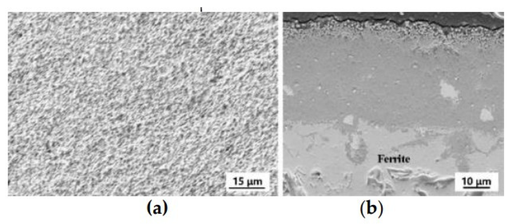
As shown in Figure 4a,b, for the MnZn ferrite sample immersed in molten salt for 20 min, fine particles appeared on the surface with a particle size of around 1 μm. The whole surface was completely uniform and dense without any defects such as holes or impurities. As shown in Figure 4b, in addition to the fine particles on the surface, the whole coating was continuous and dense inside and there was a mutual diffusion between the film and the substrate. The thickness of the film was 38 ± 7 μm.
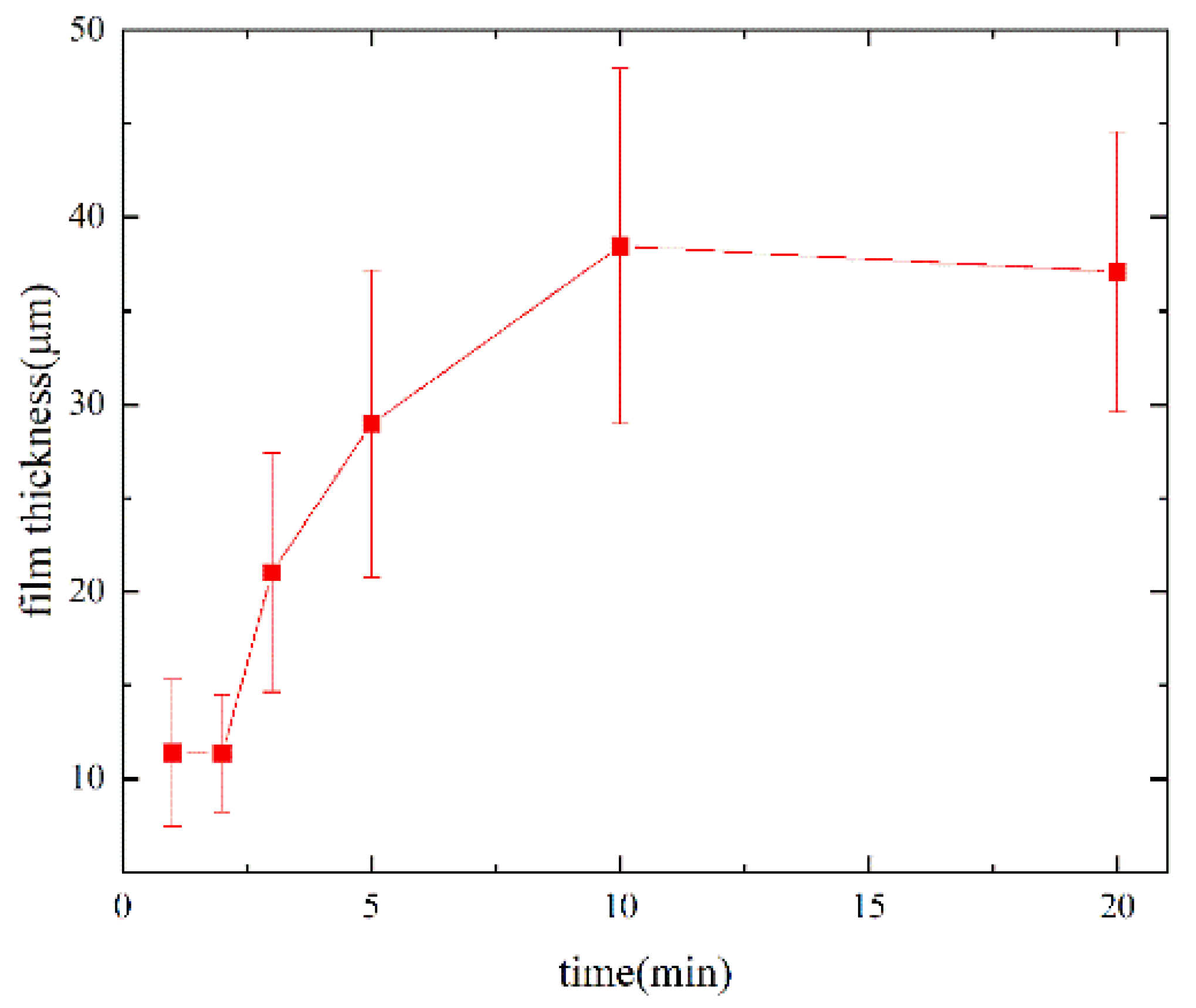
The surface and cross-section of the samples with an immersion time of 1, 3, 5 and 10 min were roughly the same as those immersed for 2 min with only a change of thickness. The thickness of the coatings was estimated from the SEM cross-section images. The dependence of the film thickness on the immersion time can be seen in Figure 5. At first, the film thickness increased with a longer immersion time. After immersion for 10 min, the film thickness increased to 39 ± 9 μm. Finally, with a further increase of the immersion time, the film thickness did not significantly increase and tended to reach an upper limit.
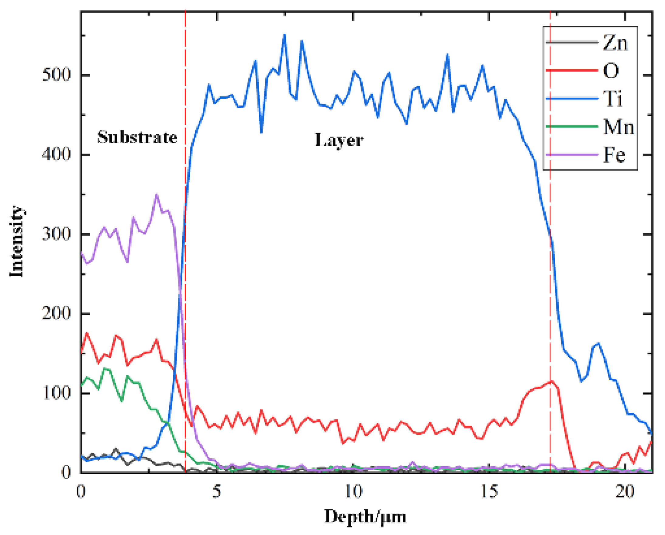
The EDS line scanning results of a cross-section of the coated MnZn ferrite with an immersion time of 2 min is shown in Figure 6. There was a layer with a thickness of 14 μm containing both Ti and O in the sample. The concentration of other elements in this zone was very low, indicating that the film was Ti oxide. The distribution of Ti and O in thin films illustrated that the composition of the film was continuous and there was an obvious interface between the film and substrate. Signals of Fe, Mn and Zn could not be detected, indicating that MnZn ferrite and the formed film did not diffuse into each other. All these were consistent with the observation from the cross-section SEM image.
The XRD patterns of the original MnZn ferrite and the coated MnZn ferrite with different immersion times are shown in Figure 7. The XRD pattern showed that the MnZn ferrite substrate was Zn0.4Mn0.6Fe2O4 with a spinel structure. For the coated MnZn ferrite with an immersion time of 2 min, 5 min and 10 min, it showed a diffraction peak of TiO2; there was no diffraction peak signal of the base ferrite. This was consistent with the SEM observation in Figure 3 that after immersion in the molten salt, a dense film covering the substrate was formed on the surface and the thickness was greater than 10 μm. Only the diffraction peak of TiO2 could be seen in the samples with an immersion time of less than 20 min. However, the Ti2O3 diffraction peak appeared for the sample immersed for 20 min and there were still a few TiO2 diffraction peaks. This showed that with the increase in the immersion time, the film changed to the conductive phase of Ti2O3.
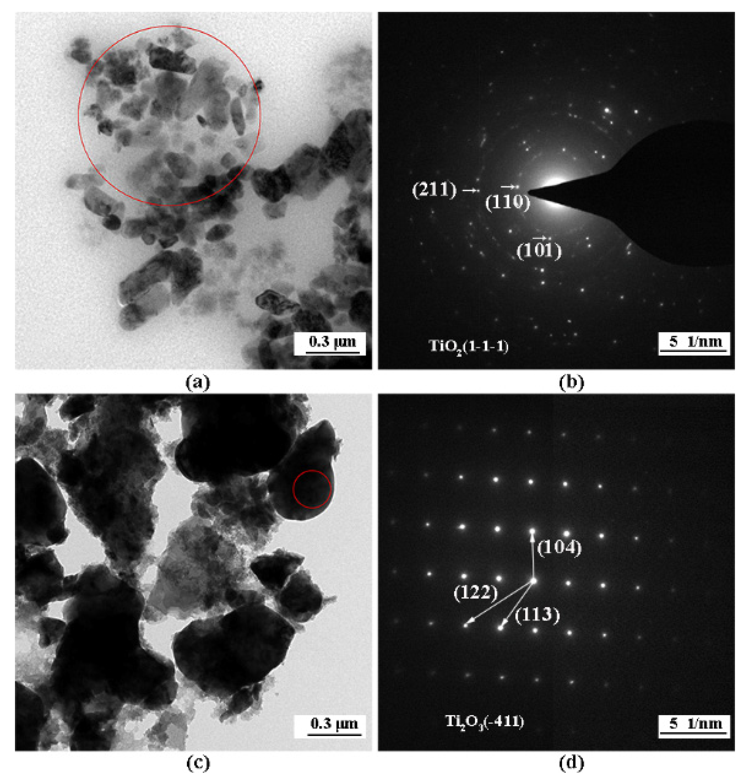
The morphology and structure of the powder prepared from the films were observed and analyzed by TEM. Figure 8a shows the TEM image of the powder samples with an immersion time of 2 min. The particles had cylindrical and spherical shapes with a size of about 0.2 μm. As shown in Figure 8b, the selected area diffraction (SAD) pattern of the designated area in Figure 8a corresponded with the crystal plane diffraction peak under the axis of the TiO2 (1-1-1) crystal band in the XRD. It indicated that these were typical TiO2 particles. The powder samples with an immersion time of 20 min were irregular blocks and the size increased to about 0.5 μm (Figure 8c). As shown in Figure 8d, the SAD pattern of the designated area in Figure 8c corresponded with the crystal plane diffraction peak under the axis of the Ti2O3 (-411) crystal band in the XRD, further proving that the film composition changed from TiO2 to Ti2O3 with the increase in the immersion time in the molten salt.
In conclusion, it could be seen that a layered structure of MnZn ferrite/Ti oxide could be obtained by the Ti modification of MnZn ferrite by the molten salt method. The film thickness increased from 10 μm to 40 μm with the immersion time and tended to reach an upper limit. Correspondingly, the composition of the Ti oxide film changed from TiO2 to Ti2O3 with an increase in the time. The TiO2 film was continuous and dense; fine particles appeared on the surface of the Ti2O3 film.
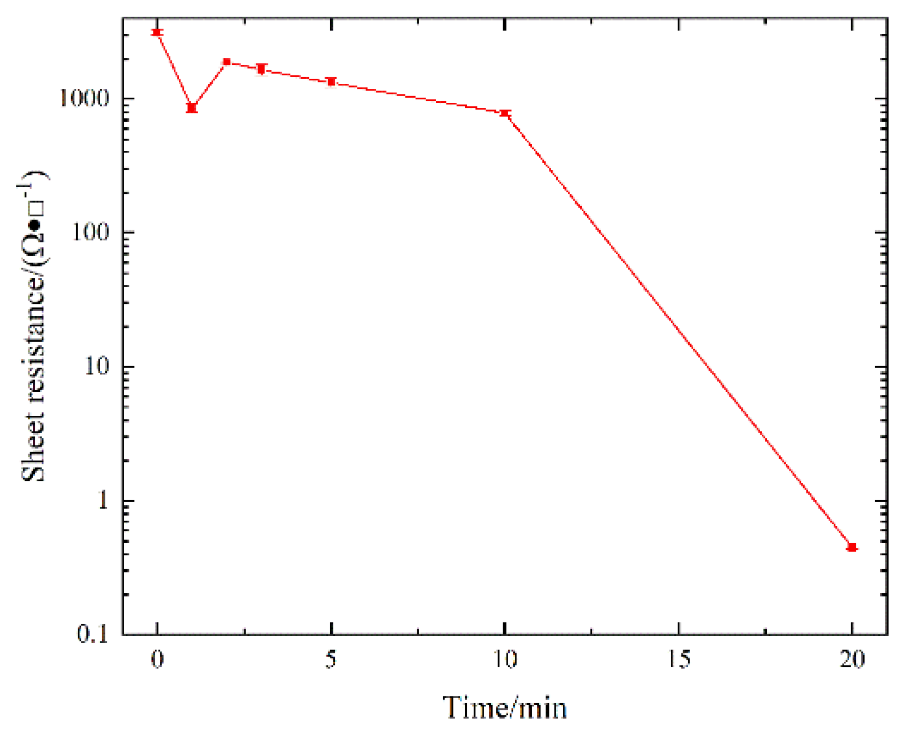
Figure 9 shows the sheet resistance curves of the coated MnZn ferrite surface with different immersion times. It can be seen that the surface sheet resistance of the MnZn ferrite substrate was about 3 kΩ/□. After being coated in the molten salt, the sheet resistance obviously decreased at first but the value was still very large (about 103 Ω/□) until the immersion time reached 20 min when the sheet resistance suddenly dropped to about 400 mΩ/□.
The change of sheet resistance could be explained and analyzed according to previous analyses of the film structure and composition. At the initial stage of the film formation, the film was composed of semiconducting TiO2 and the sheet resistance had a steady downward trend but the overall value was still about 103 Ω/□ and the conductivity was very poor [23]. With an increase in the immersion time, the film thickness and the proportion of Ti in the film increased until being immersed for 20 min, when the film became a metal-like phase Ti2O3 and the sheet resistance suddenly dropped to 10−1 Ω/□. The Ti2O3 sheet resistance was similar to the work of Joel [24]. It had a good conductivity and the potential to combine with metals [25].

4. Discussion

Generally, the process of Ti modification on a material surface by the molten salt method is divided into four steps [26,27]: (i) in the molten salt, the Ti atom in the sponge Ti reacts with Ti4+ in K2TiF6 to form Ti2+; (ii) the Ti2+ ions are adsorbed on the material surface and a disproportionation reaction occurs to produce Ti and Ti4+, then Ti precipitates on the substrate surface and Ti4+ is dissolved in the molten salt; (iii) the Ti precipitated onto the substrate reacts with the substrate to form the corresponding modified film; (iv) through the diffusion between the film and the substrate, the process of (iii) continues and the thickness of the film increases.
In the molten salt system of this experiment, K2TiF6 dissociated Ti4+ at the reaction temperature of 850 °C and the following reactions occurred after adding Ti powder:
Ti 4 + + Ti ( s ) = 2 Ti 2 +   ( in   molten   salt ) .
The disproportionation reaction of Ti2+ in the molten salt on the surface of MnZn ferrite was as follows:
2 Ti 2 + = Ti 4 + + Ti   ( on   the   substrate ) .
Ti is an active element; according to the experimental results of the XRD, the TiO2 film was formed at the beginning. Therefore, the following reactions could occur at the initial stage of the film formation between Ti on the surface of MnZn ferrite and the substrate at the experimental temperature. The ΔG was calculated by HSC at a temperature of 850 °C:
3 Ti + 2 Fe 2 O 3 = 3 TiO 2 + 4 Fe
G = 278.568   kJ / mol
Ti + 2 ZnO = TiO 2 + 2 Zn
G = 65.074   kJ / mol
Ti + 2 MnO = TiO 2 + 2 Mn
G = 32.641   kJ / mol .
As the ΔG of Reaction (3) was the smallest, Reaction (3) should have occurred first in the molten salt. Fe is easy to dissolve in molten salt [28].
With the increase in the immersion time, uniform TiO2 films were formed on the surface of MnZn ferrite. Ti, Fe and O then diffused through the TiO2 thin film layer. At the same time, Reaction (3) continued and the thickness of the TiO2 film continued to increase. When the TiO2 film increased to a certain thickness, the diffusion rate of Fe and O could not keep up with the deposition rate of Ti. The proportion of Ti in the film increased and the thickness tended to reach an upper limit. Finally, when the immersion time reached 20 min, the composition of the film became Ti2O3. The following reaction occurred:
2 Ti + Fe 2 O 3 = Ti 2 O 3 + 2 Fe
G = 162.742   kJ / mol
Ti + 3 TiO 2 = 2 Ti 2 O 3
G = 46.916   kJ / mol .
Reaction (6) should always occur in the early stage of film formation; however, with the inclusion of Reaction (8), only Reaction (3) occurred when Fe2O3 was sufficient.
3 Ti 2 O 3 + Fe 2 O 3 = 6 TiO 2 + 2 Fe
G = 68.909   kJ / mol .
With the increase in the immersion time, the diffusion between the film and the substrate continued then the particle size of the film increased, precisely because TiO2 became Ti2O3 with the increase in the proportion of Ti and molecular clusters, accordingly. In addition, due to the lack of O, the surface of the Ti2O3 film was loose particles.

5. Conclusions

(1) In NaCl–KCl–K2TiF6 molten salt, Ti oxide coatings could be deposited on the surface of MnZn ferrite by a molten salt reaction.
(2) The composition and properties of the film deposited on the ferrite surface were related to the length of the coating time: When the coating time was less than 20 min, the main component of the film was TiO2. When the coating time exceeded 20 min, the main component of the film was Ti2O3. Moreover, the film and the substrate were closely bonded without pores and with a clear interface. In this method, the thickness of the coating had an upper limit of approximately 40 μm.
(3) The Ti2O3 film coated on MnZn ferrite by the molten salt reaction had good electrical conductivity. It could be used as a preset layer for the further electroplating of metal electrode materials such as Cu and Ag.

Author Contributions

Conceptualization, H.W., L.Y. and W.Z.; methodology, L.Y., W.Z. and G.Y.; validation, E.C. and G.Y.; investigation, H.W.; resources, C.W., L.Y., W.Z. and G.Y.; data curation, H.W.; writing—original draft preparation, H.W.; writing—review and editing, H.W., L.Y., W.Z. and G.Y.; funding acquisition, L.Y. All authors have read and agreed to the published version of the manuscript.

Funding

This research was funded by the National Natural Science Foundation of China, grant Nos. 12175032 and 11675246.

Institutional Review Board Statement

Not applicable.

Informed Consent Statement

Not applicable.

Data Availability Statement

Data sharing is not applicable to this article.

Acknowledgments

The authors acknowledge the Shanghai Institute of Applied Physics, Chinese Academy of Sciences, Shanghai 201800, China.

Conflicts of Interest

The authors declare no conflict of interest.

References

  1. Sugimoto, M. The Past, Present, and Future of Ferrites. J. Am. Ceram. Soc. 2004, 82, 269–280. [Google Scholar] [CrossRef]
  2. Skołyszewska, B.; Tokarz, W.; Przybylski, K.; Kakol, Z. Preparation and Magnetic Properties of MgZn and MnZn Ferrites. Phys. C Supercond. 2003, 387, 290–294. [Google Scholar] [CrossRef]
  3. Reza, M.G.; Daee, S.S.; Hossein Mohseni, H.; Torkian, S.; Ghasemi, M.; Ameriannejad, M.; Hoseinizade, M.; Pirnia, M.; Pourjafar, D.; Pourmahdavi, M. Structure and Magnetic Properties of Mn-Zn Ferrite Synthesized by Glycine-Nitrate Auto-Combustion Process. AMR 2011, 409, 520–525. [Google Scholar] [CrossRef]
  4. Thakur, P.; Chahar, D.; Taneja, S.; Bhalla, N.; Thakur, A. A review on MnZn ferrites: Synthesis, characterization and applications. Ceram. Int. 2020, 46, 15740–15763. [Google Scholar] [CrossRef] [PubMed]
  5. Houbi, A.; Aldashevich, Z.A.; Atassi, Y.; Telmanovna, Z.B.; Saule, M.; Kubanych, K. Microwave absorbing properties of ferrites and their composites: A review. J. Magn. Magn. Mater. 2021, 529, 167839. [Google Scholar] [CrossRef]
  6. Almessiere, M.; Slimani, Y.; Trukhanov, A.; Sadaqat, A.; Korkmaz, A.D.; Algarou, N.; Aydın, H.; Baykal, A.; Toprak, M.S. Review on functional bi-component nanocomposites based on hard/soft ferrites: Structural, magnetic, electrical and microwave absorption properties. Nano-Struct. Nano-Objects 2021, 26, 100728. [Google Scholar] [CrossRef]
  7. Zaquine, I.; Benazizi, H.; Mage, J.C. Ferrite thin films for microwave applications. J. Appl. Phys. 1988, 64, 5822–5824. [Google Scholar] [CrossRef]
  8. Lim Ju, D.; Rong, E.P.J.; Riko, I.M.; Sharif, A.; Zhang, L.J.; Long, L.F.; Lip, G.C.; Zhong, C.; Rhee, D.; Woo, M.; et al. Study of Thin Film Metallization Adhesion in Ceramic Multichip Module. In Proceedings of the 2012 IEEE 14th Electronics Packaging Technology Conference (EPTC), Singapore, 5–7 December 2012. [Google Scholar]
  9. Hasuyama, H.; Shima, Y.; Hayashi, N.; Sakamoto, I.; Baba, K.; Motoyama, M. Adhesion enhancement of metallized thin films on alumina ceramics by ion beam mixing. Nucl. Instrum. Methods Phys. Res. Sect. B Beam Interact. Mater. At. 1993, 80–81, 1304–1307. [Google Scholar] [CrossRef]
  10. Zhang, Y.; Cai, D.; Zhao, C.; Zhu, M.; Gao, Y.; Chen, Y.; Liang, X.; Chen, H.; Wang, J.; Wei, Y.; et al. Nonreciprocal Isolating Bandpass Filter With Enhanced Isolation Using Metallized Ferrite. IEEE Trans. Microw. Theory Tech. 2020, 68, 5307–5316. [Google Scholar] [CrossRef]
  11. Konishi, Y. Novel dielectric waveguide components-microwave applications of new ceramic materials. Proc. IEEE 1991, 79, 726–740. [Google Scholar] [CrossRef]
  12. Kim, Y.-H.; Lee, J.-W.; Kim, H.-J.; Yun, Y.-H.; Nam, S.-M. Silver Metallization for Micro-wave Device Using Aerosol Deposition. Ceram. Int. 2012, 38, S201–S204. [Google Scholar] [CrossRef]
  13. Equbal, A.; Sood, A.K. Metallization on FDM Parts Using the Chemical Deposition Technique. Coatings 2014, 4, 574–586. [Google Scholar] [CrossRef] [Green Version]
  14. De Juan, S.; Gordo, E.; Jiménez-Morales, A.; Sirois, F. Study on the Growth and Properties of Electrolessly Deposited Thin Copper Coatings on Epoxy-Based CFRP. Coatings 2020, 10, 271. [Google Scholar] [CrossRef] [Green Version]
  15. Shih, C.; Su, H.; Lin, C.; Ko, T.; Chen, C.; Huang, J.; Chou, S.; Peng, C.; Hsieh, C.; Tsai, M.; et al. Direct plating of Cu on ALD TaN for 45 nm-node Cu BEOL metallization. In Proceedings of the IEEE International Electron Devices Meeting, San Francisco, CA, USA, 13–15 December 2004. [Google Scholar]
  16. Testov, O.A.; Komlev, A.E.; Gareev, K.G.; Khmelnitskiy, I.K.; Luchinin, V.V.; Sevost’Yanov, E.N.; Testov, I.O. Providing a Specified Level of Electromagnetic Shielding with Nickel Thin Films Formed by DC Magnetron Sputtering. Coatings 2021, 11, 1455. [Google Scholar] [CrossRef]
  17. Hu, Y.; Rasadujjaman, M.; Wang, Y.; Zhang, J.; Yan, J.; Baklanov, M.R. Study on the Electrical, Structural, Chemical and Optical Properties of PVD Ta(N) Films Deposited with Different N2 Flow Rates. Coatings 2021, 11, 937. [Google Scholar] [CrossRef]
  18. Behboudi, F.; Kakroudi, M.G.; Vafa, N.P.; Faraji, M.; Milani, S.S. Molten salt synthesis of in-situ TiC coating on graphite flakes. Ceram. Int. 2021, 47, 8161–8168. [Google Scholar] [CrossRef]
  19. Daoush, W.M.; Park, H.S.; Hong, S.H. Fabrication of TiN/cBN and TiC/diamond coated particles by titanium deposition process. Trans. Nonferrous Met. Soc. China 2014, 24, 3562–3570. [Google Scholar] [CrossRef]
  20. Dubrovskiy, A.; Okunev, M.; Makarova, O.; Kuznetsov, S. Superconducting Niobium Coatings Deposited on Spherical Substrates in Molten Salts. Coatings 2018, 8, 213. [Google Scholar] [CrossRef] [Green Version]
  21. Stern, K.H. Metallurgical and Ceramic Protective Coatings; Springer Science & Business Media: London, UK, 1996. [Google Scholar]
  22. Wei, P.; Qiliang, H.; Jian, C.; Juan, C.; Huang, Y. Mechanism of titanium deposition on Al2O3 ceramic surface by molten salt reaction. Mater. Lett. 1997, 31, 317–320. [Google Scholar] [CrossRef]
  23. Zhang, D.; Yang, K.; Li, Y.; Liu, Y.; Zhu, M.; Zhong, A.; Cai, X.; Fan, P.; Weizhong, L. Employing TiO2 Buffer Layer to Improve VO2 Film Phase Transition Performance and Infrared Solar Energy Modulation Ability. J. Alloys Compd. 2016, 684, 719–725. [Google Scholar] [CrossRef]
  24. Stryhalski, J.; Diego, A.D.; Rebouta, L.M.; César Sagás, J.; José Tavares, C.; Fontana, L.C. Nb-Doped Ti2O3 Films Deposited through Grid-Assisted Magnetron Sputtering on Glass Substrate: Electrical and Optical Analysis. Mat. Res. 2019, 22. [Google Scholar] [CrossRef] [Green Version]
  25. Singh, V.; Pulikkotil, J. Electronic phase transition and transport properties of Ti2O3. J. Alloys Compd. 2016, 658, 430–434. [Google Scholar] [CrossRef]
  26. Li, J.; Wei, P.; Qiliang, H.; Chen, J.; Zhang, Z. Mechanism of titanium deposition on AlN surface by molten salt reaction. Mater. Lett. 2003, 57, 1369–1373. [Google Scholar] [CrossRef]
  27. Wei, P.; Li, J.; Chen, J. Titanium Metallization of Si3N4 Ceramics by Molten Salt Reaction: Coating Microstructure and Brazing Property. Thin Solid Film. 2002, 422, 126–129. [Google Scholar] [CrossRef]
  28. Polovov, I.B.; Abramov, A.V.; Rebrin, O.I.; Volkovich, V.A.; Denisov, E.; Griffiths, T.R.; Iain May, I.; Kinoshita, H. Corrosion of Stainless Steel in NaCl-KCl Based Melts. ECS Trans. 2010, 33, 321. [Google Scholar] [CrossRef] [Green Version]
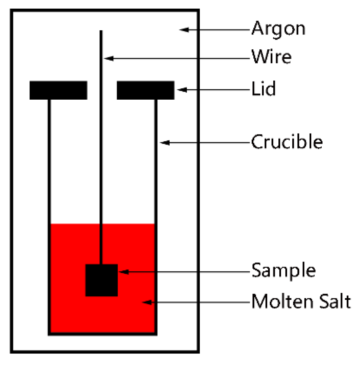
Figure 1. Schematic diagram of the experimental setup.
Coatings 12 00298 g001
Figure 2. SEM images of MnZn ferrite surface.
Coatings 12 00298 g002
Figure 3. SEM images of MnZn ferrite immersed in molten salt for 2 min: (a) surface section; (b) cross-section.
Coatings 12 00298 g003
Figure 4. SEM images of MnZn ferrite immersed in molten salt for 20 min: (a) surface section; (b) cross-section.
Coatings 12 00298 g004
Figure 5. Film thickness versus immersion time.
Coatings 12 00298 g005
Figure 6. EDS line scanning results of a cross-section of MnZn ferrite immersed in molten salt for 2 min.
Coatings 12 00298 g006
Figure 7. XRD patterns of MnZn ferrite and MnZn ferrite immersed in molten salt for different times.
Coatings 12 00298 g007
Figure 8. TEM images of MnZn ferrite surface particles: (a) MnZn ferrite immersed in molten salt for 2 min; (b) the corresponding SAD pattern of (a); (c) immersed in molten salt for 20 min; (d) the corresponding SAD pattern of (c). The indexing indicates the existence of a TiO2 phase for 2 min and a Ti2O3 phase for 20 min.
Coatings 12 00298 g008
Figure 9. The sheet resistance curves of MnZn ferrite surface with different immersion times.
Coatings 12 00298 g009
Publisher’s Note: MDPI stays neutral with regard to jurisdictional claims in published maps and institutional affiliations.