Abstract
The development of anticorrosion coatings on copper has raised tremendous interest in material science. Using a milling method, regular rough structures were fabricated, and after chemical deposition with AgNO3 solution and the modification of stearic acid, a superhydrophobic copper substrate could be obtained. The surface morphological study showed a dendritic microstructure, and a rectangular surface bulge produced by milling was distributed on the copper substrate. The coatings showed the surface water contact angle could be as high as 158.4°. The best anti-corrosion coating was the sample milled with the cutter tip distance of 0.30 mm. The as-prepared superhydrophobic sample has a good self-cleaning effect. Scratched with a knife and abraded by friction, the copper substrate still maintained good superhydrophobic nature. The coating was mechanically stable and possessed good corrosion resistance.
1. Introduction
Copper is an important material and has wide applications in different fields for its excellent properties. However, Cu is susceptible to corrosion in humid environments or in different acids, which limits its practical application and thus makes the development of anticorrosion coatings on copper a great challenge and an urgent task for copper applications [1]. Superhydrophobic surfaces are surfaces with a water contact angle (CA) larger than 150° and have gained more and more attention in material science for their advantages in self-cleaning [2], anti-fouling [3], and corrosion resistance applications [4]. By preventing the contact of a corrosive medium with a metal substrate, superhydrophobic surfaces can provide effective corrosion protection and reduce contaminants’ adherence to the metal [5,6,7]. Many studies have successfully prepared superhydrophobic Cu surfaces via different methods, such as etching [8,9], sol-gel [10,11], chemical vapor deposition [12,13], and laser processing [14]. Generally, most methods combine two steps to obtain superhydrophobicity: One is surface roughening and the other is modifications with low-surface-energy materials. For example, Forooshani et al. [15] prepared a superhydrophobic Cu surface through dislocation etching and shot peening. The contact angle of the surface could reach as high as 153° after stearic acid modification. Ashoka et al. [16] developed a copper superhydrophobic surface with over-oxidized polypyrrole by an electrochemical route. 14. Ta et al. [14] prepared a superhydrophobic copper/brass surface using nanosecond laser ablation. The sample turned superhydrophobic after 11 days. Many present methods are still restricted by many factors such as the high cost of expensive reagents, severe experiment conditions, sophisticated equipment, and complicated fabrication processes. In addition to these factors, poor mechanical properties and weak chemical stability have become major barriers to the practical application of superhydrophobic Cu surfaces [17]. On one hand, they are vulnerable to dirt or polluted environments, which destroy their properties and shorten their service life. On the other hand, superhydrophobic surfaces are easily abraded by scratch or friction, and the surface structure can be seriously damaged, compromising the corrosion resistance of superhydrophobic surfaces [18]. Milling is a common machining method, which has extremely high machining accuracy and potential application prospects in controllable micro-scale surface preparation. In order to improve the poor stability and durability of superhydrophobic surfaces, we explored a preparation method of a superhydrophobic surface combining mechanical and chemical methods.
In this paper, a surface roughening method for preparing a micro-nano double-layer structure on a copper substrate via mechanical milling combined with chemical deposition is proposed, and after the surface was modified with stearic acid, a superhydrophobic sample of excellent mechanical durability and stability was prepared on copper. After the friction test, the sample still maintained a high surface contact angle and excellent corrosion resistance. Different from the traditional surfaces prepared solely via chemical methods, the microstructure of the roughened surface constructed via the milling method is regular and orderly, and the surface coarsening structure can be controlled by adjusting milling parameters. The preparation process is not only simple but also efficient, and it is also free from expensive chemical reagents and sophisticated equipment. These advantages are rather feasible for industrial production and can provide a reference for future engineering applications of other metals.
2. Materials and Methods
2.1. Materials
An H62 brass plate, obtained from Dongguan Minghao Metal Technology Co., Ltd. (Guangdong, China), was cut into a sheet of 15 mm × 15 mm × 5 mm. Stearic acid (C18H36O2, AR) and hydrogen peroxide (H2O2, AR) were obtained from Shanghai Yien Chemical Technology Co., Ltd. (Shanghai, China). Concentrated hydrochloric acid (HCl, 36%) was provided by Changzhou Xuhong Chemical Co., Ltd. (Jiangsu, China). Anhydrous ethanol was obtained from Fuyu Fine Chemical Co., Ltd. (Tianjin, China), and sodium chloride (NaCl) and silver nitrate (AgNO3) were purchased from Xilong Scientific Co., Ltd. (AR, Shantou, China).
2.2. Methods
2.2.1. Milling Processing
Before milling, the H62 brass was polished using SiC sandpaper (300#, 600#), and then rinsed with deionized water. The Cu plate was processed by 4 mm diameter end-milling with an 11,000 r/min spindle speed, a 400 mm/min feed speed, and a 0.1 mm milling depth. The surface of the ground sample was parallel and flat. Then, a flat-bottomed sharp knife with a tip diameter of 0.1 mm was used to replace the end-milling. After manual tool setting, the milling process of the Cu block surface was completed with a spindle speed of 12,000 r/min, a feed rate of 30 mm/min, a cutting depth of 0.01 mm, and a total cutting depth of 0.05 mm. The tip distances of the milling cutter were 0.25, 0.30, and 0.35 mm, respectively, and samples with three distances noted as MS-25, MS-30, and MS-35 were then prepared. After the machining process, the samples were taken out and washed with clean water to dispose of the remaining milling chips. Then, they were kept in a beaker containing a solution of anhydrous ethanol, and the mixture was rinsed ultrasonically for 10 min to remove the coolant on the sample surfaces during milling.
2.2.2. Chemical Treatment
The Cu samples were cleaned and placed into a HCl/H2O2 mixed solution (H2O: HCl: H2O2 = 4: 1: 1) for 30 s to remove burrs on the Cu surface. The AgNO3 solution was prepared with 0.2 g AgNO3 and 50 mL deionized water. Cu samples were soaked in the AgNO3 solution for 2 min and taken out and dried. The samples were placed into 1% stearic acid solution for 10 min, then rinsed using deionized water, and kept dry by an oven [19]. Finally, MS/Silver@SA samples of different cutter tip distances were prepared, and the preparation flow chart is presented in Figure 1.
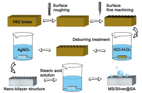
Figure 1.
Flowchart of the preparation.
2.3. Sample Characterization
Field emission scanning electronic microscopy (SEM, SU5000, HITACHI, 5.0 KV, Tokyo, Japan) was used to examine the morphologies of the samples. Chemical compositions and valence states of the samples were analyzed by X-ray photoelectron spectroscopy (XPS, 250Xi, Thermo Scientific, Waltham, MA, USA) with the Al Kα X-ray source (hν = 1486.6 eV) and Fourier Transform Infrared spectroscopy (FTIR, IRAffinity-1S, Shimadzu Corporation, 4000–450 cm−1, Tokyo, Japan). The phase structure was studied by X-ray diffraction (XRD, Smartlab9, Rigaku Corporation, Tokyo, Japan). The test for the water contact angle (CA) was carried out using a contact angle measuring instrument (SDC-200, Xindin Precision Instrument Co., Ltd., Dongguan, China) by taking the average CA value of 6 μL droplets on five different positions of each sample. The surface energy of the sample was calculated by the Zisman method. In order to test the self-cleaning performance of the sample, chalk dust was spread on the surface of the sample, and deionized water was dropped. To test the stability, horizontal and vertical net scratches were made on the sample surface with a blade. When the sample was tilted, deionized water was dropped, and the movement of the droplets at the interface of the surface scratches was observed and recorded. The sample was then placed flat on 2000# silicon carbide sandpaper, and a 100 g weight was placed on the sample to test its durability. The sample was connected to a tension meter and pulled so the sample moved horizontally and uniformly as much as possible. With a distance of 21 cm as a cycle, the sample was pulled 5 times, 10 times, 15 times, and 20 times, then it was taken down and weighed and the contact angle was measured.
The corrosion test of the MS/Silver@SA samples of different cutter tip distances was carried out in a 3.5 wt% NaCl solution with an exposure area of 1 cm2 at room temperature with a standard three-electrode system through an electrochemical workstation (CS2350H, Wuhan CorrTest Instruments Corp., Ltd. Wuhan, China). Potential values are given relative to the silver chloride electrode (SCE). The corrosion potential (Ecorr) and corrosion current density (Icorr) were obtained by the Tafel extrapolation method, along with CorrView software and the calculation of polarization resistance (Rp, Ω∙cm2) with the initial potential of potential scanning of −0.5 V, the terminal potential of 1 V, and the potential interval of data acquisition of 0.5 mV. Before the test, the sample was soaked in the solution for 30 min for stability.
3. Results and Discussion
3.1. Sample Characterization
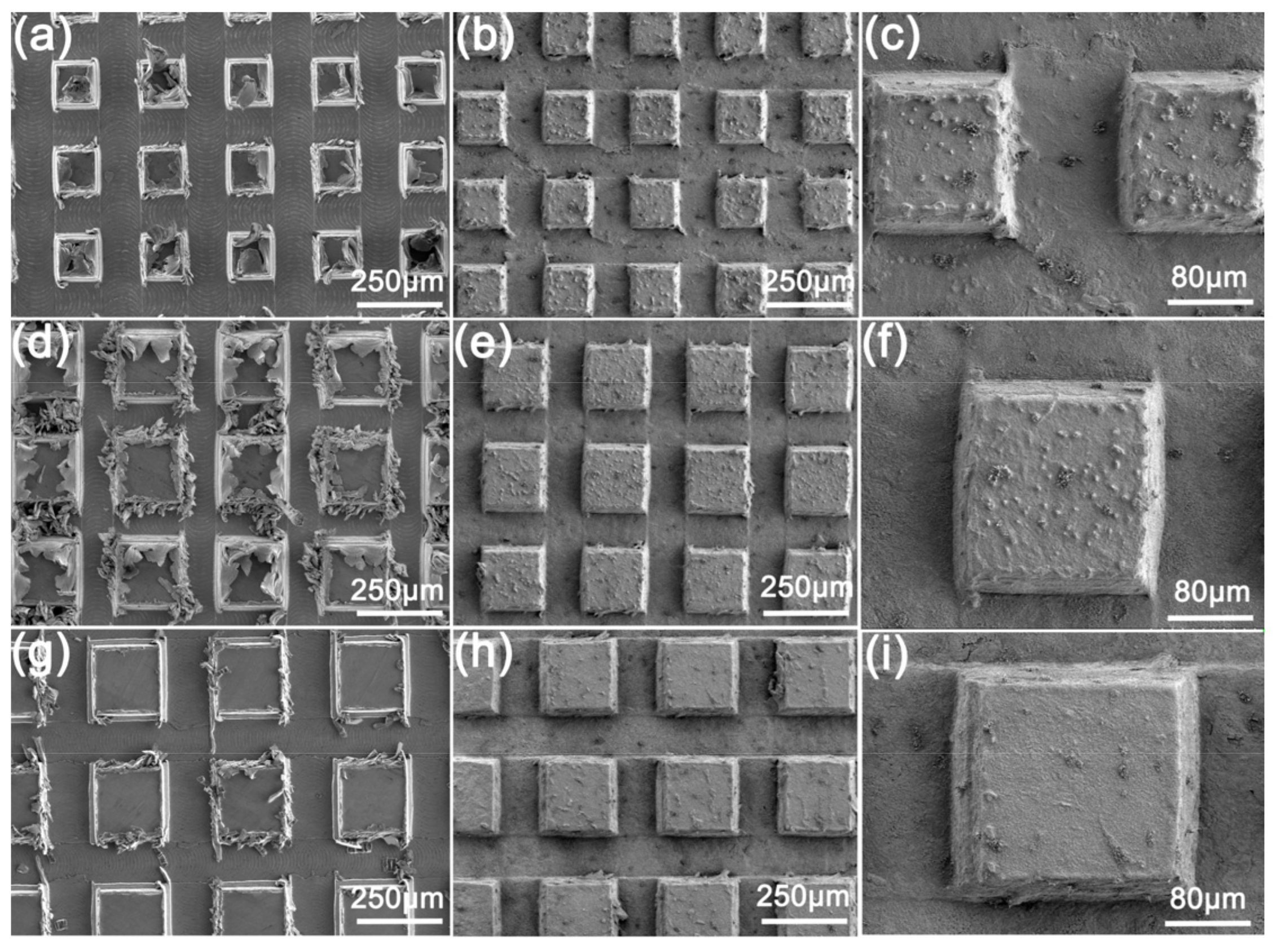
SEM images of the surfaces milled with different cutter tip distances are shown in Figure 2. Figure 2a shows the milled sample MS-25 with a cutter tip spacing of 0.25 mm. Figure 2d shows the milling spacing of sample MS-30 is 0.30 mm, and Figure 2g shows the milling spacing of sample MS-35 with 0.35 mm. It can be observed that many thread-like scratches appear on the groove of the milled Cu surface, left by flat-bottomed sharp knives during milling finishing (Figure 2a). Meanwhile, a large number of blocky and strip burrs are also seen. They are attached to the bumps on the Cu surface, which are mainly left by machine tool vibration or tool wear (Figure 2d).

Figure 2.
SEM images of the surface after milling with different cutter tip distances: (a) MS-25, (d) MS-30, (g) MS-35; and SEM images of the surface after deburring: (b,c) MS-25, (e,f) MS-30, (h,i) MS-35.
Figure 2b,c,e,f,h,i shows SEM images of the milled Cu sample after deburring, in which the milling tip spacing of Figure 2b,c is 0.25 mm, that of Figure 2e,f is 0.30 mm, and that of Figure 2h,i is 0.35 mm. After deburring, the scratches generated by the rough machining and the finish machining cannot be seen (Figure 2b). Meanwhile, most of the burrs produced by the milling around the bump were basically gone (Figure 2c) because of the reaction of HCl/H2O2 solution with Cu surface, leading to the corrosion of Cu. Figure 2i shows some larger burrs remain. After the reaction, some of the remaining burrs clustered on the bump surface, with some small bumps distributed on the sample surface (Figure 2f).
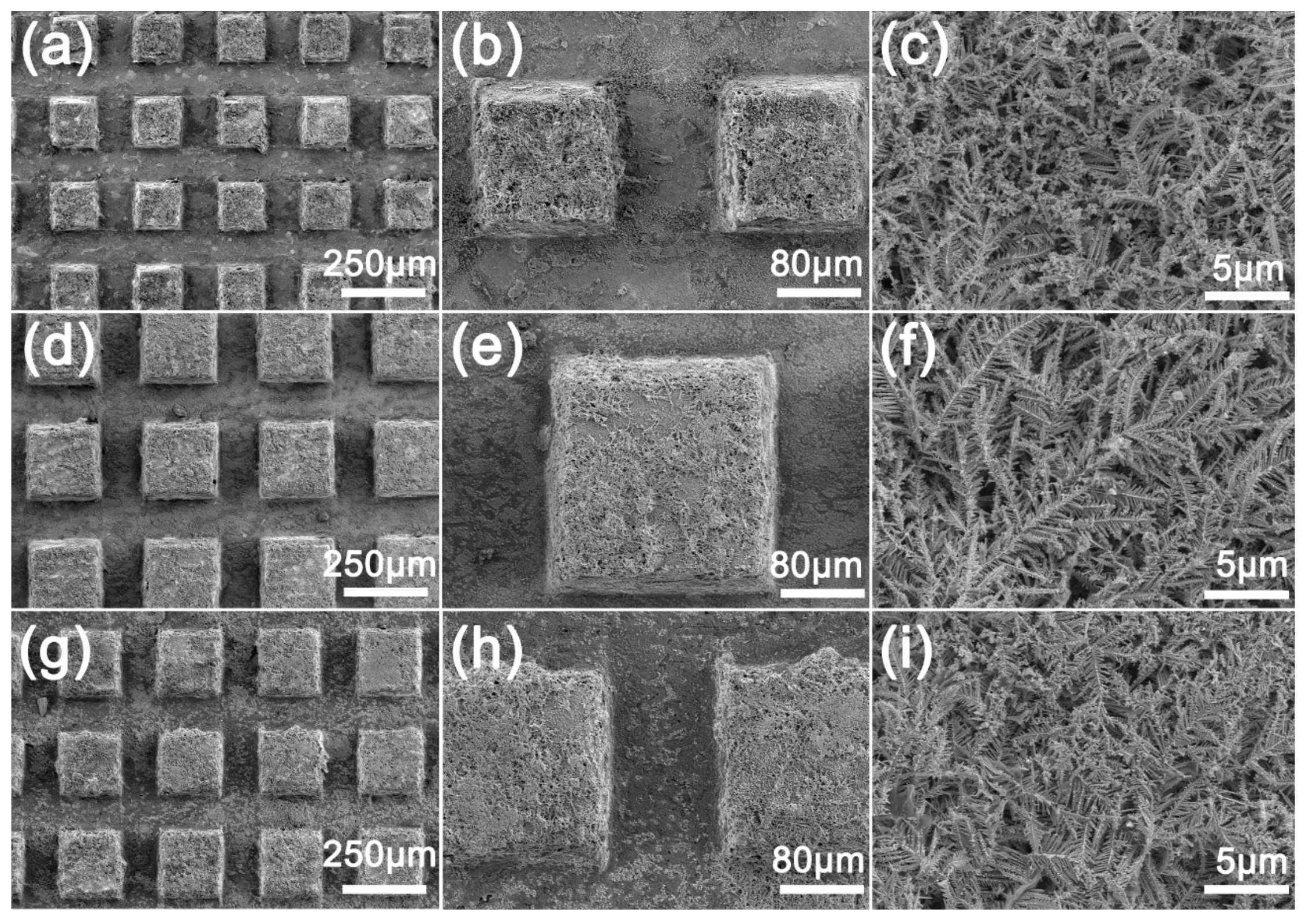
Figure 3 shows the SEM image of the deburred sample after the reaction with AgNO3. The surface of the sample becomes very rough, and the micro/nano hierarchical structure can be observed both on the protrusion and the groove surfaces (Figure 3h). It can be observed that the microstructure formed by deposition at the protrusion is thicker than that at the groove (Figure 3b) because the protrusion first makes contact with the liquid and chemical deposition occurs (Figure 3g,h). In the high-power SEM images (Figure 3c,f,i), it can be seen that many dendritic microstructures are formed layer by layer on the surface at the deposition. At the same time, the morphology of dendritic microstructures on the surfaces with different machining intervals is similar, which shows that different milling intervals have little effect on the morphology of the surface microstructures. The dendritic microstructure and the rectangular surface bulge produced by milling form a micro/nano surface with a hierarchical structure.

Figure 3.
SEM images of MS/Silver@SA sample surface: (a–c) MS-25/Silver@SA, (d–f) MS-30/Silver@SA, (g–i) MS-35/Silver@SA.
3.2. Surface Wettability Analysis
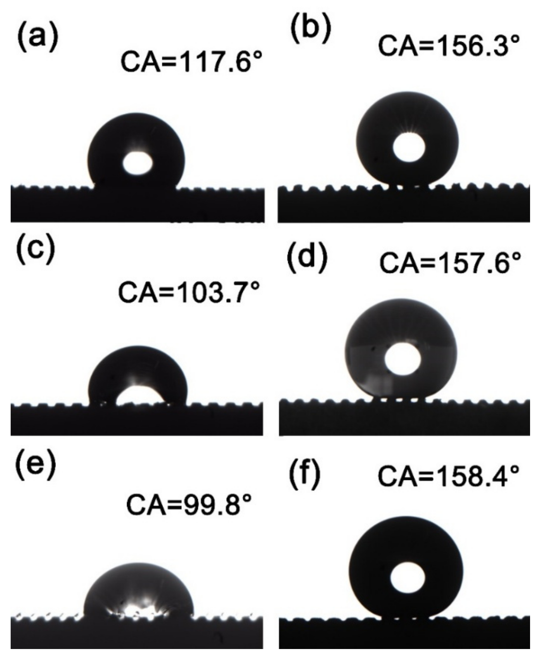
Figure 4 shows the contact angles (CA) of different samples. Figure 4a shows the CA of the milled and deburred MS-25 sample, which is 117.6°, and Figure 4b shows the CA of the MS-25/Silver@SA sample, which is 156.3°. In Figure 4c,d, when the cutter tip distance is 0.30 mm, the surface CA of the deburred MS-30 sample is 103.7° (Figure 4c), and the surface CA of the chemically deposited and stearic-acid-modified MS-30/Silver@SA sample is 157.6° (Figure 4d). With the cutter tip distance of 0.35mm, the deburred MS-35 sample in Figure 4e has a surface CA of 99.8°, and the stearic-acid-modified MS-35/Silver@SA sample in Figure 4f has a surface CA of 158.4°. The surface CA of untreated H62 copper block was 88.9°. The surface energy of each sample is also provided, as shown in Table 1.
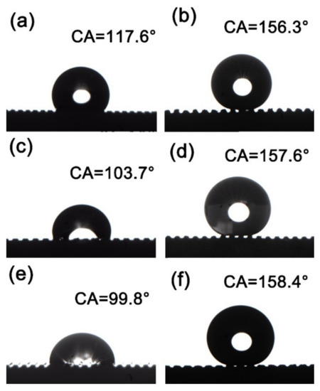
Figure 4.
Contact angle (CA) images of milling samples with different cutter tip distances under different conditions: (a) MS-25, (b) MS-25/Silver@SA, (c) MS-30, (d) MS-30/Silver@SA, (e) MS-35, (f) MS-35/Silver@SA.

Table 1.
Surface energy of different samples.
Droplets usually stay on the rough surface in two states. The first state is that liquid fills every gap of the rough surface, which is called the Wenzel wet state. In the second state, the liquid droplets only make contact with the peaks protruding from the rough surface, while a large number of air pockets remain in the gaps between the peaks, which is called the Cassie wet state. In the Wenzel state, the liquid–solid contact in a large area makes the liquid droplets strongly adhere to the rough surface, and the movement of the liquid droplets becomes extremely difficult. In contrast, in the Cassie state, due to the incomplete contact between the liquid and solid, the adhesive force between liquid droplets and the rough surface is low, and there are many air pockets at the same time. When sufficient roughness and an appropriate contact angle are reached, the superhydrophobic condition of highly movable liquid droplets can be realized. The experimental results show that, after milling and deburring treatment, the Cu surface has a CA larger than that of the unprocessed one. As the cutter tip distance decreases, the CA of the sample surface increases, and the contact between the surface and the droplets conforms to the Wenzel model where the air at the groove is drained by water and the surface is in a state of high viscosity [20]. Figure 4b,d,f shows the surface of the sample modified by chemical deposition and stearic acid after milling. With gaps between the sample surface and the droplets, the contact between the surface and the droplets is in accordance with the Cassie model [21]. Here, the air in the groove is not emptied, and the CA of the sample increases with the increase in the cutter tip distance.
3.3. Surface Composition Analysis
In the experiment, it was found that the three samples, MS-25/Silver@SA, MS-30/Silver@SA, and MS-35/Silver@SA, showed the same results in the surface composition analysis of this section. Therefore, we take the experimental data of MS-30/Silver@SA as an example.
Figure 5 is the XRD diffraction pattern of the MS/Silver@SA sample. The sample shows characteristic peaks at 38.02°, 44.17°, and 77.42°, which are determined by the (111), (200), (311) crystal plane of Ag (PDF 04-0783). Diffraction peaks also appear at 43.31°, 50.46°, and 74.08°, and the corresponding Cu crystal plane indices are (111), (200), and (220). The characteristic peaks at 42.22°, 49.02°, 72.03°, and 87.13° are from Cu0.64Zn0.36 (PDF 026-0534), which indicates that the substrate appears due to partial penetration of the X-ray [22]. In addition, there are no other obvious diffraction peaks, which indicates that the purity of the MS/Silver@SA sample is high.
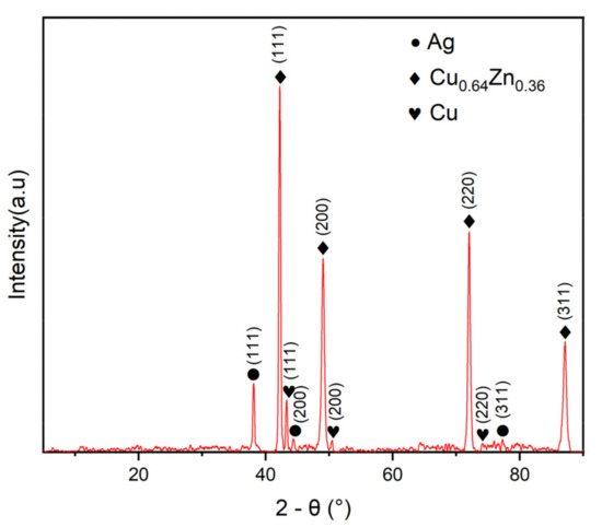
Figure 5.
X-ray diffraction (XRD) pattern of MS/Silver@SA sample.
The chemical composition of the MS/Silver@SA sample was analyzed by Fourier transform infrared spectrometer (FTIR). Figure 6 (A) is the infrared spectrum of stearic acid, while Figure 6 (B) is that of the MS/Silver@SA sample surface. The absorption peak of stearic acid appears at ~1700 cm−1, which is attributed to the stretching vibration of -COOH. When the reaction occurs between stearic acid and the sample, at 1703 cm−1, the free -COOH band of stearic acid disappears, while the absorption peak caused by the -COOH bond appears at 1536 cm−1, so the absorption peak shifted [23]. The bending vibration of -OH at 934 cm−1 is also reduced [24]. Meanwhile, FTIR shows that the peaks at 2916 cm−1 and 2848 cm−1 in stearic acid are assigned to the stretching vibration and asymmetric stretching vibration of the C-H bond, and there is no shift of peak [25]. The results showed the reaction of the CH3(CH2)12COO- functional group from stearic acid took place with the Cu sample, indicating the successful modification of stearic acid on the copper sample.
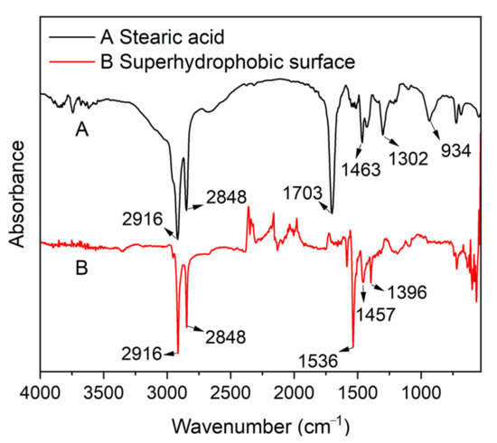
Figure 6.
Fourier transform infrared spectra (FTIR) of (A)—stearic acid and (B)—MS/Silver@SA sample.
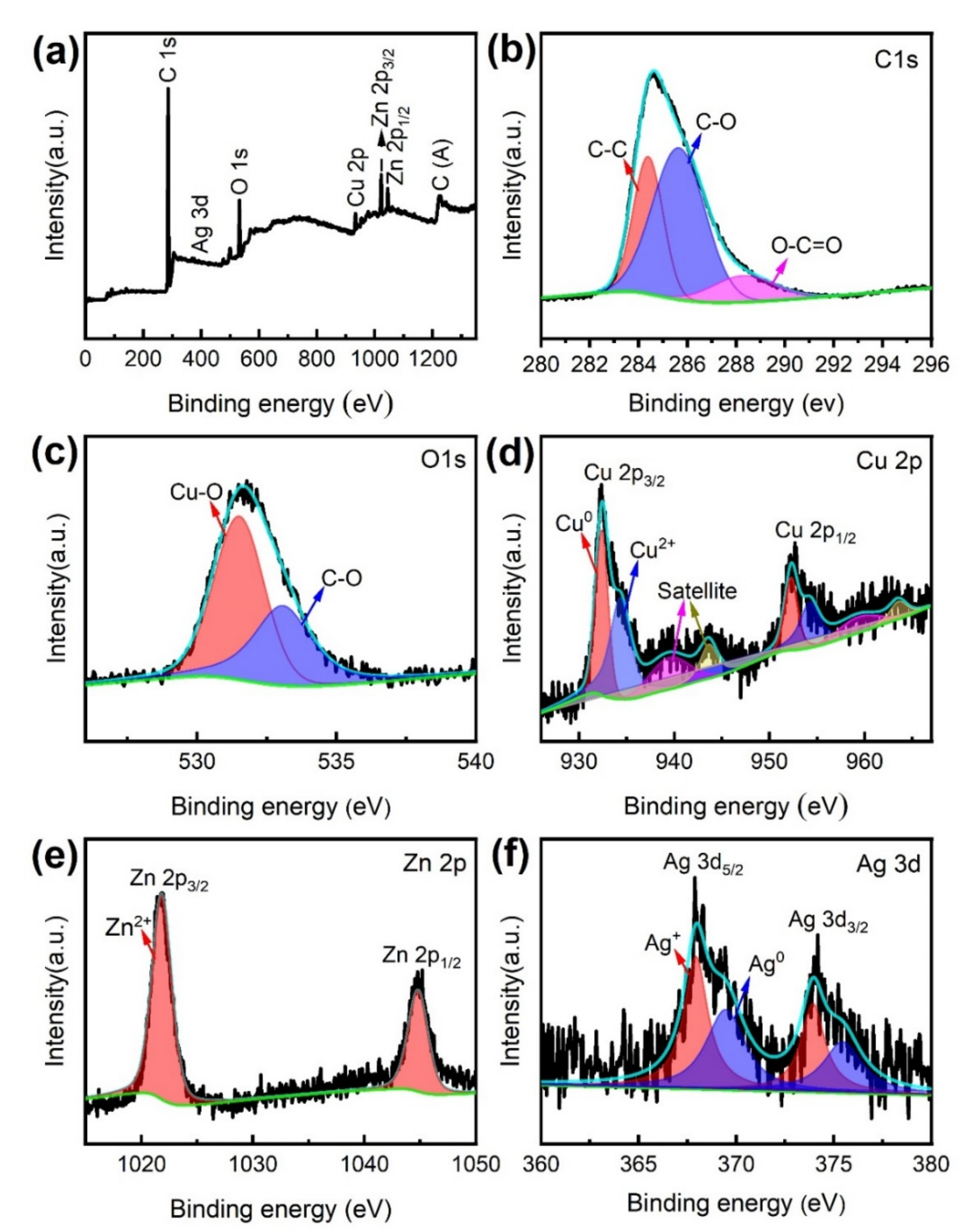
XPS was used to further examine the chemical composition and characteristics of the MS/Silver@SA sample. Figure 7 is the XPS full scanning spectrum and narrow scanning spectrum of the MS/Silver@SA sample surface. As shown in Figure 7a, different elements such as C, O, Cu, Zn, and Ag exist in the sample, and the narrow scanning spectra of C1s, O1s, Cu2p, Zn2p, and Ag3d are shown in Figure 7b–f. The C 1s peak includes three characteristic peaks (Figure 7b). The first is the carbon–carbon single bond (C-C), with the characteristic binding energy of 284.8 eV. The second is the carbon–oxygen single bond (C-O) of ~286 eV, and the third is carboxyl (O-C=O), located at ~289 eV. Figure 7c shows the two characteristic peaks of O 1s. The state of metal oxidation can be displayed through the peak at 531.5 eV, and the other peak appears at 532.8eV, which is the carbon–oxygen single bond (C-O). Figure 7d shows the narrow scanning spectrum of the characteristic element Cu 2p. At 933.5 eV and 953.5 eV, the binding energy of the Cu 2p3/2 peak and the Cu 2p1/2 peak appear, manifesting the oxidation state of Cu. Figure 7d shows the narrow scanning spectrum of the characteristic element Zn 2p. The characteristic peaks of Zn 2p3/2 and Zn 2p1/2 are at 1022.4eV and 1045.1eV, respectively, indicating the oxidation state of Zn. Figure 7f is the narrow scanning spectrum of the element Ag 3d. The characteristic peaks of Ag 3d5/2 and Ag 3d3/2 are at ~368 eV and 373.4eV, and Ag mainly exists in the form of elemental Ag. Through XPS, it can be observed that when the reaction occurs between AgNO3 and Cu, elemental Ag is deposited on the Cu surface.
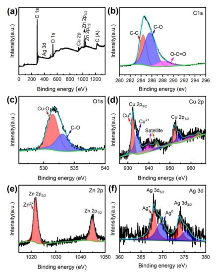
Figure 7.
(a) XPS full scanning spectrum of MS/Silver@SA sample, narrow scanning spectrum (b) C 1s, (c) O 1s, (d) Cu 2p, (e) Zn 2p, (f) Ag 3d.
3.4. Analysis of Surface Corrosion Resistance
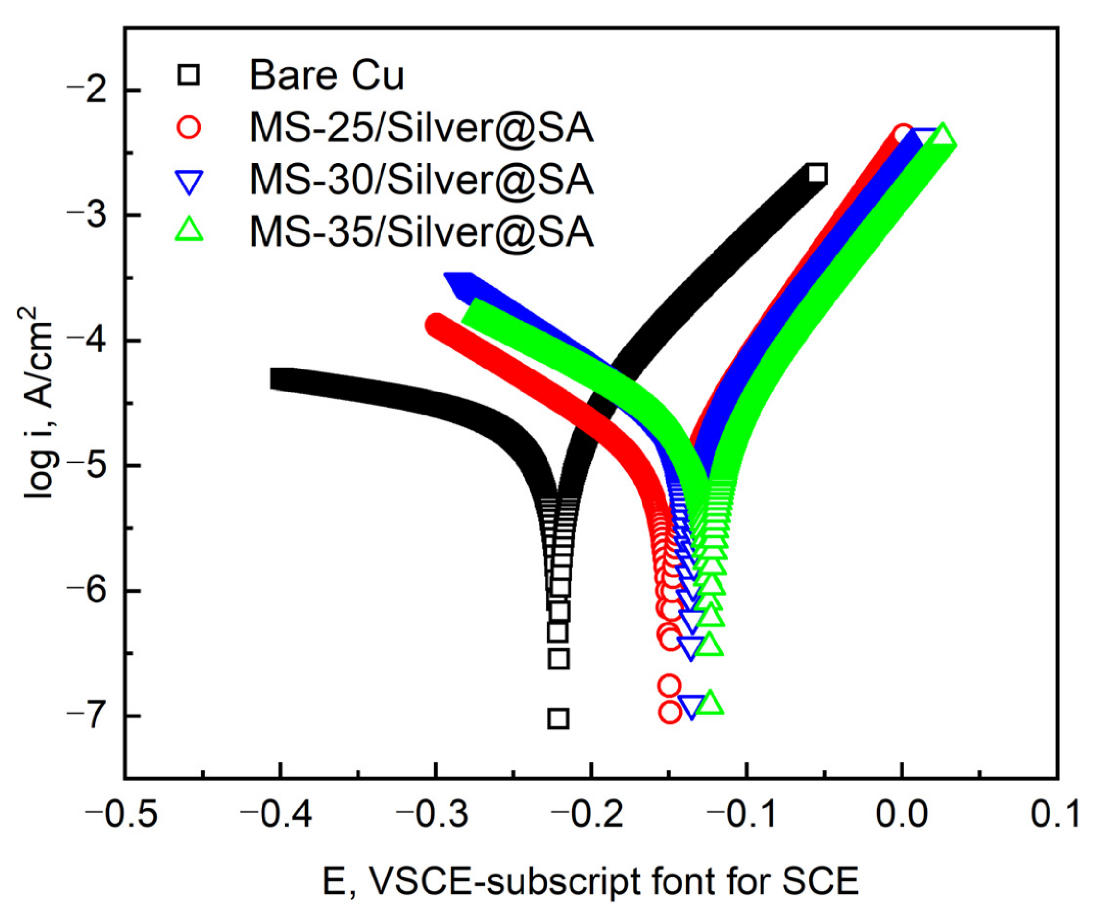
Figure 8 shows the dynamic potential polarization curve of the Cu substrate with MS/Silver@SA samples of different cutter tip distances in a 3.5 wt.% NaCl solution. Table 2 shows the detailed data, among which the corrosion potential (Ecorr) and corrosion current density (Icorr) are measured by the Tafel extrapolation method [26], and the corrosion rate X (mm/a) was calculated by Equation (1), where W1 (g) is the weight of samples before the corrosion test; W2 (g) is the weight of samples after the corrosion test; A (cm2) is the sample surface area; T (h) is the experimental time; and D (g/cm3) is the sample density.
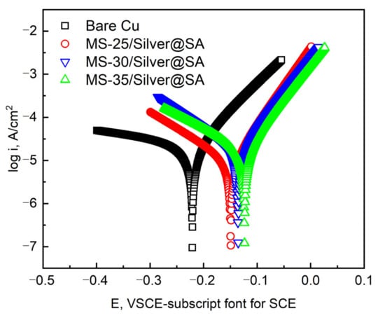
Figure 8.
Corrosion polarization curves of different samples in 3.5 wt.% NaCl solution.
Table 2.
Electrochemical data of the polarization curves obtained from the samples.
The results show that the Icorr and Ecorr of the Cu substrate are 2.92 × 10⁻⁵ A/cm² and −0.2208V, respectively. The Icorr and Ecorr of MS-25/Silver@SA, MS-30/Silver@SA, and MS-35/Silver@SA samples are 1.80 × 10⁻⁵ A/cm², 9.87 × 10⁻⁶ A/cm², and 1.88 × 10⁻⁵ A/cm² and −0.1354, −0.1492, and −0.1236 V, respectively. Based on electrochemical theory, with good corrosion resistance, materials have low positive values of Icorr and Ecorr [27]. The results show that the corrosion current density of the MS/Silver@SA sample is lower than that of the Cu substrate, which indicates that the surface of the MS/Silver@SA sample really improves the corrosion resistance of the Cu substrate. When the cutter tip distance is 0.30 mm, the sample has the best corrosion protection performance, while the current density and corrosion speed are the lowest.
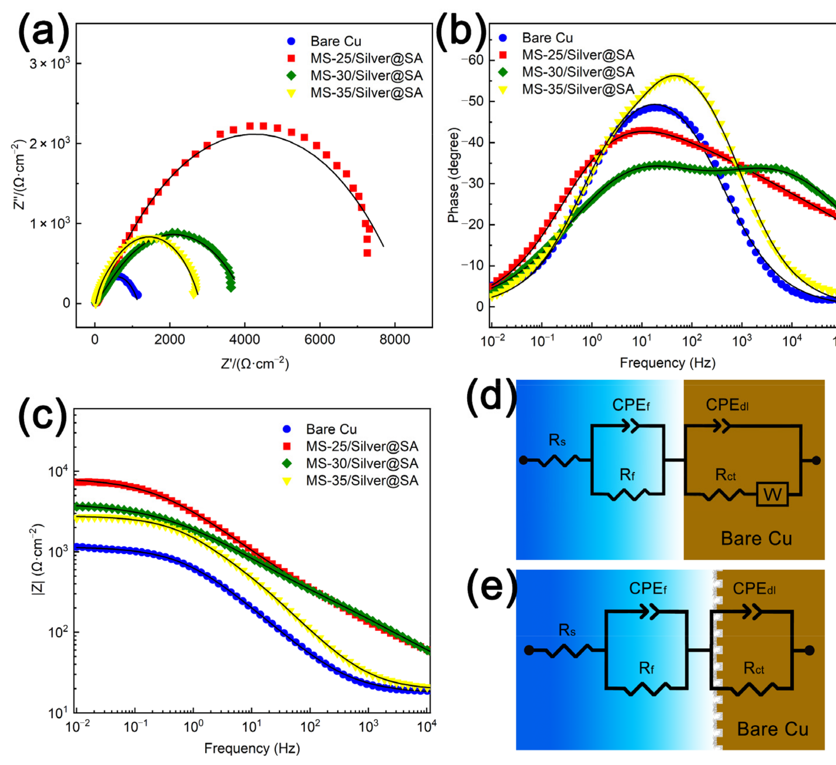
To study the corrosion resistance of MS/Silver@SA samples, the Nyquist plot, impedance modulus curve, and phase angle plots of each sample in the 3.5 wt% NaCl solution are analyzed, and the results can be seen in Figure 9a–c. Figure 9a shows the Nyquist image where the diameter of the semicircle curve is connected to the charge transfer resistance. The larger the semicircle diameter, the better the corrosion resistance of the sample [28]. It can be seen that the Cu substrate has the smallest semicircle diameter, which is about 300 Ω∙cm−2. Meanwhile, the capacitance semicircle diameter of the MS/Silver@SA sample is higher, indicating the better corrosion resistance of the MS/Silver@SA sample. Generally, the higher the |Z| value from the Bode diagram, the better the corrosion resistance [29]. From the Bode diagram in Figure 9c, the MS/Silver@SA sample has a higher |Z| value. The high phase angle in the high-frequency domain indicates that the sample has good repulsion performance, while the large modulus in the low-frequency domain shows the improvement of the corrosion resistance. MS-25/Silver@SA and MS-30/Silver@SA both show high phase angles in the low-frequency domain and high-frequency domain (Figure 9b). The results show the good corrosion protection of the MS/Silver@SA sample.

Figure 9.
Cu substrate and MS/Silver@SA samples in 3.5 wt.% NaCl solution. (a) Nyquist image; (b) phase angle image; (c) Bode image; (d) equivalent circuit simulation of experimental data of Cu substrate; (e) equivalent circuit simulation based on MS/Silver@SA sample experimental data.
Figure 9d,e shows the equivalent circuit model (Ecs) of Nyquist images of the Cu substrate and MS/Silver@SA samples, in which Rs is the solution resistance, Rf is the film resistance, and Rct is the charge transfer resistance. W is the Warburg impedance caused by the dissolution and diffusion of the Cu surface [30]. As the sample surface is uneven, the constant phase element (CPE) is used to replace the pure capacitor as a non-ideal capacitor set for circuit fitting, which has a better fitting effect in an equivalent circuit [31]. The Rct of superhydrophobic Cu samples is higher than that of the Cu substrate, indicating the good corrosion protection of MS/Silver@SA samples. Table 3 shows the detailed fitting data.
Table 3.
Equivalent circuit fitting results of the EIS data.
3.5. Self-Cleaning Effect
When the water flow is at a certain angle to the superhydrophobic surface, the water droplets on its surface are no longer in a flowing state, but rather in an ejection state [32]. The radian of ejection is related to the speed of water flow. The higher the speed, the greater the radian of ejection, which is the reason for the low adhesion of the surface and is an important basis for judging the self-cleaning performance of superhydrophobic surfaces [33]. In Figure 10a–c, the water flow reflection test of the MS/Silver@SA sample surface shows that when the needle nozzle sprays water flow onto the sample surface, the water flow in contact with the surface of the test sample is quickly bounced off, and the water flow will not destroy the surface of the sample and make no change to the wettability of the sample. The results show that the MS/Silver@SA sample has low surface adhesion and good self-cleaning property.
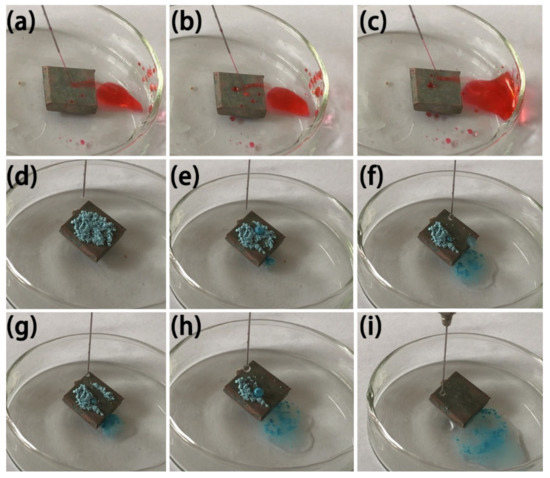
Figure 10.
Image of water jet reflection and self-cleaning process on MS/Silver@SA sample. (a,b,c) water flow reflection test, (d) Dripping, (e,f) Water drop contact, (g,h) Water drop rolling, (i) Water droplets roll out.
To test the self-cleaning effect of the MS/Silver@SA sample, the antifouling performance test was carried out, using blue chalk dust as the test powder. We ground the blue chalk into powder, sprinkled it on the surface, and placed the sample slanted in the petri dish, as shown in Figure 10d. Figure 10e–i shows the rolling of water droplets off the sample surface will take away part of the blue chalk dust absorbed by the water droplets. With more and more water droplets, chalk dust can be easily removed with the rolling droplets (Figure 10i). The test results show the good self-cleaning effect of the MS/Silver@SA sample.
3.6. Mechanical Durability and Stability
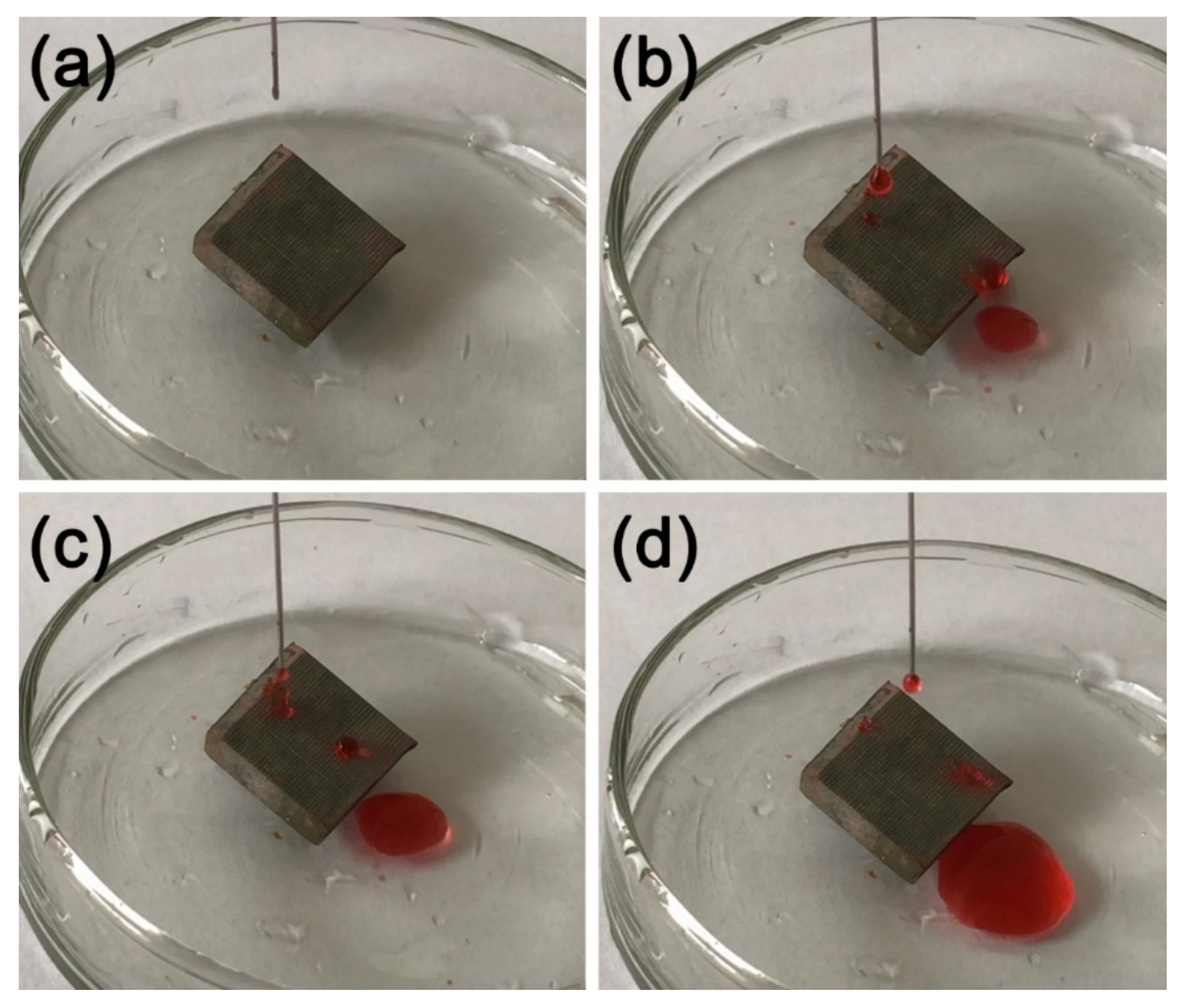
Scratch resistance and friction resistance are often performed to test the mechanical durability and stability of superhydrophobic surfaces [34]. In this study, a knife scratching test and a wear test were employed to study the mechanical properties of MS-30/Silver@SA samples. The milling parameters of the copper block of the MS-30/Silver@SA sample are 4 mm diameter end-milling, a 0.1 mm milling depth, a 0.05 mm milling depth by a flat-bottomed sharp knife with 0.1 mm tip diameter 5 times, and 0.30 mm tip spacing.
A knife was used to scratch the surface horizontally and vertically, as shown in Figure 11a. A deionized water solution with red ink was dropped on the tilted, scratched sample. Figure 11b–d shows the dripping water droplets can still roll easily on the scratched sample surface, proving the good scratch resistance of the MS/Silver@SA sample.
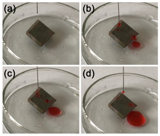
Figure 11.
Knife scraping test image of MS/Silver@SA sample. (a) Dripping, (b,c) Water drop contact, (d) Water droplets roll out.
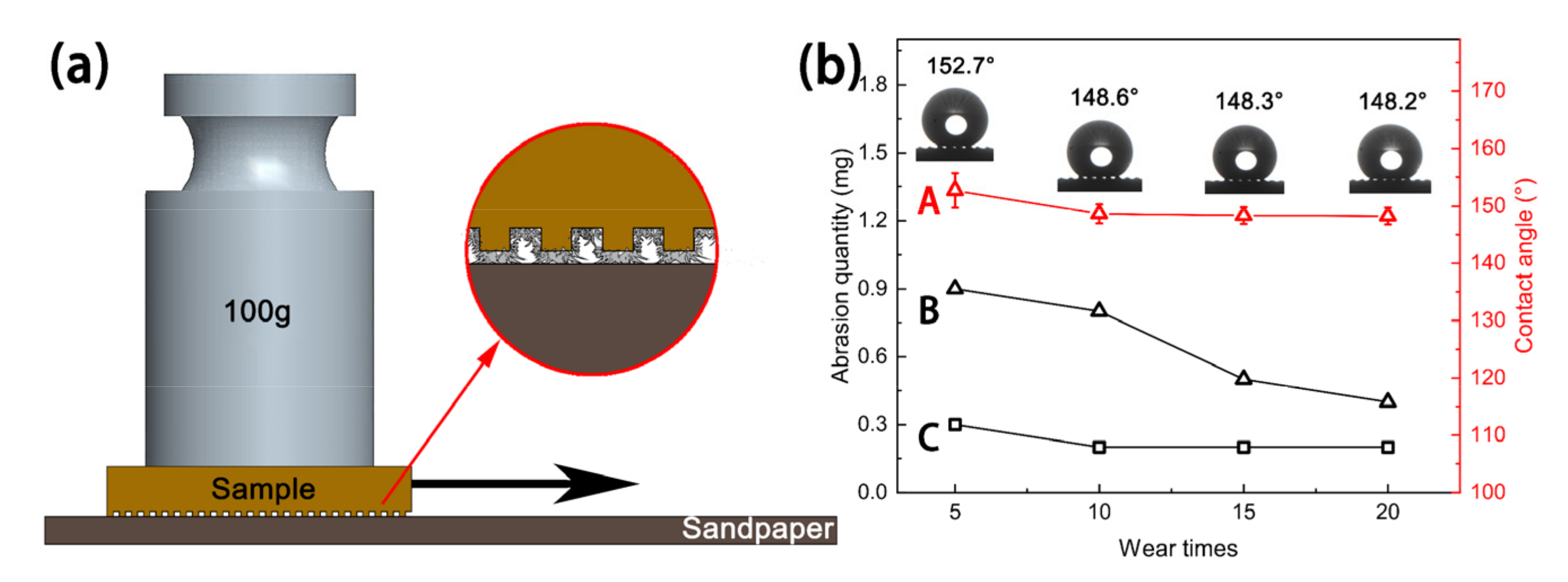
In a previous study, Ras et al. [35] reported that linear abrasion could be used to evaluate the mechanical durability of the superhydrophobic coating, and this wear-test method could be applied in most lab research studies and industrial production, which can generate a large, uniform surface suitable for wetting measurements. In this work, linear friction and wear tests were performed on the sample to study the mechanical durability of the sample surface. First, 2000# silicon carbide sandpaper, a 100g weight, and a tension meter were prepared. The sandpaper was then horizontally spread on a table and the untreated Cu substrate and MS-30/Silver@SA sample were placed under the tension meter. A parallel force was enacted to ensure the samples could move at a uniform speed, and the pulling distance was 21 cm, as shown in Figure 12a. The wear of the Cu substrate and the MS-30/Silver@SA sample was recorded by stretching them 5, 10, 15, and 20 times, respectively, as shown in Figure 12b.

Figure 12.
(a) Schematic diagram of wear test, (b) variation diagram of wear amount and contact angle (CA): (A)—The surface CA change curve of MS-30/Silver@SA sample; (B)—the surface wear curve of MS-30/Silver@SA sample; (C)—the surface wear curve of Cu substrate.
To test the superhydrophobic performance of the MS/Silver@SA sample after friction and wear, the wettability of the MS-30/Silver@SA sample after the wear test was measured. Figure 12 shows the CA of the MS-30/Silver@SA sample surface with different durations of pulling. After being pulled five times, the CA of the sample is 152.7°, 4.1°, lower than that of 157.6° before the friction experiment (Figure 4d). The surface after friction and wear still maintains superhydrophobicity. After undergoing pulling 10, 15, or 20 times, the surface contact angles of these samples are stable and all above 148°, and after undergoing pulling 20 times, the CA of the surface is 148.2°. The surface conforms to the Cassie model, showing a state with high CA and low viscosity. Air is not entirely discharged at the bottom groove. The increase in the pulling makes no significant change to the sample surface, which proves the good mechanical durability of the ms/silver@sa sample.
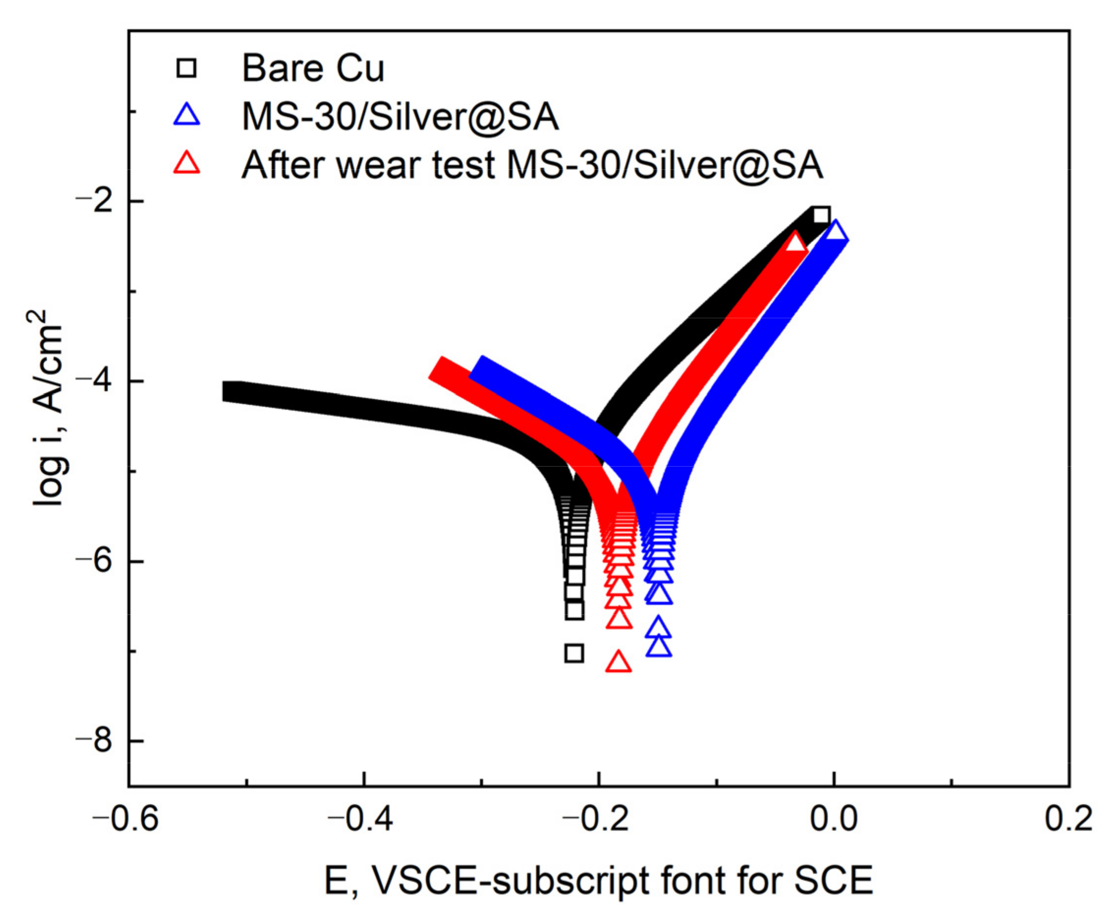
The MS-30/Silver@SA sample pulled 20 times in the friction experiment is used to test the corrosion resistance of the worn sample, using a 3.5 wt% sodium chloride aqueous solution as the electrolyte (Figure 13). Data are shown in Table 4. After the friction experiment, the corrosion current density of the MS-30/Silver@SA sample becomes 1.04 × 10⁻⁵ A/cm², lower than that of the Copper substrate, which is 2.92 × 10⁻⁵ A/cm². At the same time, the corrosion rate of the MS-30/Silver@SA sample after the friction experiment is similar to that before the friction experiment.

Figure 13.
Potentiodynamic polarization curves of Cu substrate, MS-30/Silver@SA sample before and after wear in 3.5 wt.% NaCl solution.
Table 4.
Electrochemical data of the polarization curves obtained from the samples.
The results show the excellent mechanical durability of the MS/Silver@SA sample, and after abrasion, the surface still possesses good corrosion resistance. This is due to the fact that when the SiC sandpaper is used to rub the MS/Silver@SA sample, the milled bumps on the MS/Silver@SA sample have the strength and hardness of the Cu substrate itself, which are hardly damaged, thus preventing the nano-silver structure deposited on the milled surface groove from being damaged (Figure 12a). The hydrophobic film layer still exists on the worn surface of the sample. The interaction between the hydrophobic film and the microstructure of the Cu surface still forms a good barrier against the NaCl solution, which slows down the progress of electro-corrosion, so the surface of the MS/Silver@SA sample can still maintain good corrosion resistance.
4. Conclusions
In this work, a method of preparing a micro/nano hierarchical structure by milling combined with chemical deposition is proposed, and after modification with a low-surface-energy substance, a superhydrophobic surface was obtained on copper substrates. Milling can be used to fabricate regular and adjustable micro-nano microstructures. After milling, rectangular protrusions are arranged regularly, and the distance between the protrusions can be controlled by adjusting the tip distance of the milling cutter. The deposited surface modified with stearic acid had the highest CA reaching 158.4°. Tests prove the prepared surface exhibits favorable superhydrophobicity, excellent self-cleaning performance, and anti-corrosion properties. In the knife scraping and friction experiment, it also maintained excellent mechanical durability and stability. The method has obvious advantages in its cheap cost, facile fabrication, and high efficiency, which can be of great benefit to research on anti-corrosion protection for other metals and contributes to the promotion of large-scale manufacturing of superhydrophobic surfaces in the industry.
Author Contributions
Conceptualization, J.Z. and L.Z.; methodology, J.Z.; software, L.Z.; validation, J.Z., C.J. and L.Z.; formal analysis, J.Z.; investigation, C.J.; resources, J.Z.; data curation, J.Z.; writing—original draft preparation, C.J.; writing—review and editing, J.Z.; visualization, L.Z.; supervision, J.Z.; project administration, J.Z.; funding acquisition, J.Z. All authors have read and agreed to the published version of the manuscript.
Funding
This research was funded by Guangxi Key Laboratory of New Energy and Building Energy Saving Foundation, grant number [No. 19-J-21-15].
Institutional Review Board Statement
Not applicable.
Informed Consent Statement
Not applicable.
Data Availability Statement
Not applicable.
Conflicts of Interest
The authors declare no conflict of interest.
References
- Shinato, K.W.; Zewde, A.A.; Jin, Y. Corrosion protection of copper and copper alloys in different corrosive medium using environmentally friendly corrosion inhibitors. Corros. Rev. 2020, 38, 101–109. [Google Scholar] [CrossRef]
- Nishimoto, S.; Bhushan, B. Bioinspired self-cleaning surfaces with superhydrophobicity, superoleophobicity, and superhydrophilicity. RSC Adv. 2013, 3, 671–690. [Google Scholar] [CrossRef]
- Liu, G.Y.; Wang, J.J.; Wang, W.; Yu, D. A novel PET fabric with durable anti-fouling performance for reusable and efficient oil-water separation. Colloid Surf. A-Physicochem. Eng. Asp. 2019, 583, 9. [Google Scholar] [CrossRef]
- Zang, D.M.; Zhu, R.W.; Wu, C.X.; Yu, X.Q.; Zhang, Y.F. Fabrication of stable superhydrophobic surface with improved anticorrosion property on magnesium alloy. Scr. Mater. 2013, 69, 614–617. [Google Scholar] [CrossRef]
- Hooda, A.; Goyat, M.S.; Pandey, J.K.; Kumar, A.; Gupta, R. A review on fundamentals, constraints and fabrication techniques of superhydrophobic coatings. Prog. Org. Coat. 2020, 142, 21. [Google Scholar] [CrossRef]
- Shi, X.T.; Zhao, L.B.; Wang, J.; Feng, L.B. Toward Easily Enlarged Superhydrophobic Copper Surfaces with Enhanced Corrosion Resistance, Excellent Self-Cleaning and Anti-Icing Performance by a Facile Method. J. Nanosci. Nanotechnol. 2020, 20, 6317–6325. [Google Scholar] [CrossRef]
- Chen, J.S.; Guo, J.; Qiu, M.B.; Yang, J.M.; Huang, D.Z.; Wang, X.L.; Ding, Y.F. Preparation of Copper-Based Superhydrophobic Surfaces by Jet-Electrodeposition. Mater. Trans. 2018, 59, 793–798. [Google Scholar]
- Xu, X.H.; Zhang, Z.Z.; Liu, W.M. Stable Biomimetic Super-Hydrophobic Copper Surface Fabricated by a Simple Wet-Chemical Method. J. Dispersion Sci. Technol. 2010, 31, 488–491. [Google Scholar] [CrossRef]
- Lv, Y.; Liu, M.Y. Corrosion and fouling behaviours of copper-based superhydrophobic coating. Surf. Eng. 2019, 35, 542–549. [Google Scholar] [CrossRef]
- Mahadik, S.A.; Pedraza, F.; Vhatkar, R.S. Silica based superhydrophobic coating for long-term industrial and domestic applications. J. Alloys Compd. 2016, 663, 487–493. [Google Scholar] [CrossRef]
- Rao, A.V.; Latthe, S.S.; Mahadik, S.A.; Kappenstein, C. Mechanically stable and corrosion resistant superhydrophobic sol-gel coatings on copper substrate. Appl. Surf. Sci. 2011, 257, 5772–5776. [Google Scholar] [CrossRef]
- Zhang, F.; Shi, Z.W.; Chen, L.S.; Jiang, Y.J.; Xu, C.Y.; Wu, Z.H.; Wang, Y.Y.; Peng, C.S. Porous superhydrophobic and superoleophilic surfaces prepared by template assisted chemical vapor deposition. Surf. Coat. Technol. 2017, 315, 385–390. [Google Scholar] [CrossRef]
- Crick, C.R.; Parkin, I.P. CVD of copper and copper oxide thin films via the in situ reduction of copper (II) nitrate-a route to conformal superhydrophobic coatings. J. Mater. Chem. 2011, 21, 14712–14716. [Google Scholar] [CrossRef]
- Ta, D.V.; Dunn, A.; Wasley, T.J.; Kay, R.W.; Stringer, J.; Smith, P.J.; Connaughton, C.; Shephard, J.D. Nanosecond laser textured superhydrophobic metallic surfaces and their chemical sensing applications. Appl. Surf. Sci. 2015, 357, 248–254. [Google Scholar] [CrossRef] [Green Version]
- Forooshani, H.M.; Aliofkhazraei, M.; Rouhaghdam, A.S. Superhydrophobic copper surfaces by shot peening and chemical treatment. Surf. Rev. Lett. 2017, 24, 6. [Google Scholar] [CrossRef]
- Ashoka, S.; Saleema, N.; Sarkar, D.K. Tuning of superhydrophobic to hydrophilic surface: A facile one step electrochemical approach. J. Alloys Compd. 2017, 695, 1528–1531. [Google Scholar] [CrossRef]
- Mohamed, A.M.A.; Abdullah, A.M.; Younan, N.A. Corrosion behavior of superhydrophobic surfaces: A review. Arab. J. Chem. 2015, 8, 749–765. [Google Scholar] [CrossRef] [Green Version]
- Zhang, D.W.; Wang, L.T.; Qian, H.C.; Li, X.G. Superhydrophobic surfaces for corrosion protection: A review of recent progresses and future directions. J. Coat. Technol. Res. 2016, 13, 11–29. [Google Scholar] [CrossRef] [Green Version]
- Fan, Y.H.; Chen, Z.J.; Liang, J.; Wang, Y.; Chen, H. Preparation of superhydrophobic films on copper substrate for corrosion protection. Surf. Coat. Technol. 2014, 244, 1–8. [Google Scholar] [CrossRef]
- David, R.; Neumann, A.W. Energy barriers between the Cassie and Wenzel states on random, superhydrophobic surfaces. Colloid Surf. A-Physicochem. Eng. Asp. 2013, 425, 51–58. [Google Scholar] [CrossRef]
- Giacomello, A.; Chinappi, M.; Meloni, S.; Casciola, C.M. Metastable Wetting on Superhydrophobic Surfaces: Continuum and Atomistic Views of the Cassie-Baxter-Wenzel Transition. Phys. Rev. Lett. 2012, 109, 4. [Google Scholar] [CrossRef] [PubMed]
- Dominic, J.; Perumal, G.; Grewal, H.S.; Arora, H.S. Facile fabrication of superhydrophobic brass surface for excellent corrosion resistance. Surf. Eng. 2020, 36, 660–664. [Google Scholar] [CrossRef]
- Li, J.; Liu, X.H.; Ye, Y.P.; Zhou, H.D.; Chen, J.M. A simple solution-immersion process for the fabrication of superhydrophobic cupric stearate surface with easy repairable property. Appl. Surf. Sci. 2011, 258, 1772–1775. [Google Scholar] [CrossRef]
- Xu, J.; Xu, J.L.; Cao, Y.; Ji, X.B.; Yan, Y.Y. Fabrication of non-flaking, superhydrophobic surfaces using a one-step solution-immersion process on copper foams. Appl. Surf. Sci. 2013, 286, 220–227. [Google Scholar] [CrossRef]
- Zhu, J.Y.; Hu, X.F. A novel and facile fabrication of superhydrophobic surfaces on copper substrate via machined operation. Mater. Lett. 2017, 190, 115–118. [Google Scholar] [CrossRef]
- McCafferty, E. Validation of corrosion rates measured by the Tafel extrapolation method. Corrosion Sci. 2005, 47, 3202–3215. [Google Scholar] [CrossRef]
- Li, H.; Wei, H.Y.; Zou, X.Y.; Wang, C.Y.; Gao, Q.; Li, Q.; Liu, Q.Z.; Zhang, J.F. Copper-based nanoribbons fabricated on a copper substrate by a liquid-solid reaction and their corrosion performance. Mater. Chem. Phys. 2020, 246, 9. [Google Scholar] [CrossRef]
- Zhang, Z.Z.; Li, Z.H.; Hu, Y.Y.; Song, A.X.; Xue, Z.X.; Li, Y.Z.; Sun, Z.Q.; Kong, X.; Xu, W.L.; Zhang, S.H. Superhydrophobic copper surface fabricated by one-step immersing method in fatty acid salt aqueous solution for excellent anti-corrosion and oil/water separation properties. Appl. Phys. A-Mater. Sci. Process. 2019, 125, 8. [Google Scholar] [CrossRef]
- Daubert, J.S.; Hill, G.T.; Gotsch, H.N.; Gremaud, A.P.; Ovental, J.S.; Williams, P.S.; Oldham, C.J.; Parsons, G.N. Corrosion Protection of Copper Using Al2O3, TiO2, ZnO, HfO2, and ZrO2 Atomic Layer Deposition. ACS Appl. Mater. Interfaces 2017, 9, 4192–4201. [Google Scholar] [CrossRef]
- Zerjav, G.; Milosev, I. Protection of copper against corrosion in simulated urban rain by the combined action of benzotriazole, 2-mercaptobenzimidazole and stearic acid. Corrosion Sci. 2015, 98, 180–191. [Google Scholar] [CrossRef]
- Wan, Y.X.; Chen, M.J.; Liu, W.; Shen, X.X.; Min, Y.L.; Xu, Q.J. The research on preparation of superhydrophobic surfaces of pure copper by hydrothermal method and its corrosion resistance. Electrochim. Acta 2018, 270, 310–318. [Google Scholar] [CrossRef]
- Zhu, J.Y.; Liao, K.J. A Facile Method for Preparing a Superhydrophobic Block with Rapid Reparability. Coatings 2020, 10, 11. [Google Scholar] [CrossRef]
- Chagas, G.R.; Celestini, F.; Raufaste, C.; Gaucher, A.; Prim, D.; Amigoni, S.; Guittard, F.; Darmanin, T. Experimental Characterization of Droplet Adhesion: The Ejection Test Method (ETM) Applied to Surfaces with Various Hydrophobicity. J. Phys. Chem. A 2018, 122, 8693–8700. [Google Scholar] [CrossRef]
- Milionis, A.; Loth, E.; Bayer, I.S. Recent advances in the mechanical durability of superhydrophobic materials. Adv. Colloid Interface Sci. 2016, 229, 57–79. [Google Scholar] [CrossRef]
- Tian, X.L.; Verho, T.; Ras, R.H.A. Moving superhydrophobic surfaces toward real-world applications. Science 2016, 352, 142–143. [Google Scholar] [CrossRef] [PubMed]


Publisher’s Note: MDPI stays neutral with regard to jurisdictional claims in published maps and institutional affiliations. |
© 2022 by the authors. Licensee MDPI, Basel, Switzerland. This article is an open access article distributed under the terms and conditions of the Creative Commons Attribution (CC BY) license (https://creativecommons.org/licenses/by/4.0/).