Article

Simulation Analysis on Flow Field of Paint Mist Recovery with Single Nozzle for Ship Outer Panel Spraying Robot

1
Navigation and Ship Engineering College, Dalian Ocean University, Dalian 116023, China
2
School of Engineering and Technology, The University of Sydney, Sydney 2006, Australia
3
School of Naval Architecture, Dalian University of Technology, Dalian 116024, China
*
Author to whom correspondence should be addressed.
Coatings 2022, 12(4), 450; https://doi.org/10.3390/coatings12040450
Submission received: 4 February 2022 / Revised: 4 March 2022 / Accepted: 7 March 2022 / Published: 25 March 2022

Abstract

:
In this paper, we design a kind of negative pressure vacuum recovery hood, arranged at the front of the spray gun nozzle by CFD simulation; this addresses the paint mist pollution problem of the robot spraying on the outer plate of the ship, and the nozzle is arranged at the center of the recovery hood. Three vacuum recovery hood schemes are designed as follows: Scheme A, a hemispherical recovery hood with a diameter of 1.2 m; Scheme B, with a diameter of 1.6 m; Scheme C, with a diameter of 2.0 m. The recovery vacuum suction holes of the three recovery hoods are arranged differently. Firstly, a mathematical model of the spraying jet for the case of 0.48 mm diameter nozzle was established, and the established nozzle jet flow field model was verified to be feasible through case simulation analysis and experimental comparison. Secondly, a detailed discussion and analysis of the simulation process was conducted focusing on Scheme A. During the simulation of Scheme A, it was found that: the air velocity at the inlet surface and the kinetic energy of the paint mist had a large impact on the simulation effect, so it is necessary to try to further improve the structure of the recovery hood. Finally, the further simulation analysis of Scheme B and Scheme C shows that Scheme C > Scheme B > Scheme A in terms of the paint mist recovery effect. It can be seen that the use of Scheme C as a shipyard robotic spray paint mist recovery shows better results, which provides a theoretical scheme for shipyards to achieve paint mist anti-fouling as soon as possible.

1. Introduction

Comparing airless spraying to air-assisted spraying, the utilization rate of paint during spraying can be increased by 10~20%, and its actual paint utilization rate can reach about 80%. However, due to the factors such as the workers’ spraying operation and environmental factors, the actual spraying efficiency is slightly lower.
With the gradual implementation of China’s intelligent manufacturing strategy and the in-depth development of technology, green shipbuilding and intelligent shipbuilding in the shipbuilding industry have become an important direction for the development of shipbuilding. To date, special attention is paid to the restoration and protection of stern tube systems from corrosive environments and wear. However, considerable damage is caused by corrosion, which primarily affects deck mechanisms [1]. Regarding the spraying construction of the hull outer panel in the dock, according to the research in the literature [2], workers hold spray guns for close-up spraying operations, using anti-sea creature paints, and other toxic paints. The diffused paint mist of the product is seriously polluting the workers, the dock and the seawater. The toxic paint mist includes highly granular solvents and solid particulate matter, such as aromatic hydrocarbons, alcohols, ketones, esters resin pollutants, with high concentration, high toxicity, flammable, explosive and other characteristics, spread into the air, pollution equipment and the surrounding environment, adsorption to the paint film to produce particles, affecting the quality of painting, especially the impact of the slow drying of the surface more obvious. It also poses a serious health risk to workers, causing central nervous system anesthesia, hematopoietic damage and respiratory lesions, white blood cell production, thrombocytopenia, dermatitis, etc., and it may even create the risk of fire and explosion. This is why it is particularly important to implement the automatic recovery of paint mist in the process of implementing robotic intelligence for the construction of hull panel spraying equipment in shipyards [3]. Currently, there is a wide range of manual or automatic hull panel spraying equipment; however, most of the spraying systems do not have a paint mist recovery function. The integration of paint mist recovery systems into the coating systems of wall-climbing robots or the greening of existing equipment in shipyards can significantly improve the green index in the field of hull painting.
The painting workers in Chinese shipyards work in a very difficult environment, where they are in close contact with paint, are contaminated by fugitive paint mist dust and have a serious occupational health crisis, as shown in Figure 1.
Aiming at the health protection problem of painting workers in shipyards, it is proposed to develop a robot with a paint mist recovery function to carry out the spraying operation. However, the recovery of paint mist from the spraying operation of the outer hull plate surface using a robot on board has been less studied at home and abroad, and it is the innovative design of this group [4,5]. Major domestic and international research has also focused on paint mist treatment in workshops. The recycling system developed by Chrysler Automotive in the USA in the 1980s uses a dry powder agent to convert waste paint into recyclable dry powder. Sanghvi H. et al. used water and organic solvents for catalysis, followed by a vacuum recovery process to produce renewable lacquers [6]. William B. et al. in a water curtain spray booth, collected overspray mist by circulating water, separated the solid components by distillation and treated as a filler for adhesives; the dregs were dehydrated and treated and the resulting powder was used as a vinyl chloride filler [7]. Buketov A. et al. developed a method of using epoxy oligomers and new compositions based on them to ensure the long-term and safe operation of marine equipment. The influence of temperature and ultrasonic treatment (UST) on the rheological properties of the pure epoxy matrix and compositions based on it is explored [8]. Savkiv V. et al. proposed an adaptive grasping device for industrial robots, which combines functions of capturing different-shape manipulation objects with control of deviations from the shape of these objects. In order to determine the design parameters of the adaptive clamping device and calculate the lifting force required by each Bernoulli gripping device (BGD), an analytical dependence was proposed, and the formula is derived for determining its position of a pneumatic sensor on the frame gripping devices [9]. Stankiewicz A. et al. uses a protective self-healing coating formed by supramolecular and “click” chemistry. The series of coating materials described mainly include polymers and gels. Diverse self-healing mechanisms and attitudes involving supramolecular interactions and dynamic covalent bonds are examined. The development of coating technology and commercial applications is also discussed [10].
Domestic research mainly focuses on some automotive processes for paint mist recovery, in which wet paint mist treatment equipment and its matching paint mist treatment agent are mostly used. One example is the working principle of the paint mist capture system used by Chery Automobile, which is to make the exhaust gas in the spray booth fully mixed with water, using different wind speeds, water baffles and multiple conversions of wind direction, so that the paint droplets and water converge and then flow into the waste paint treatment room through the pipeline for treatment [11,12]. The process of “rotary adsorption + catalytic combustion” or “activated carbon adsorption + desorption + catalytic combustion” is used to maximize the purification efficiency [13,14,15,16].
In a large ship, the paint spraying on the surface of the inner and outer plates of the dock is large, Figure 2 shows the painting workers in Chinese shipyards working at high altitude to paint at close range. In a large tanker, for example, the paint mist generated by the spraying process of the inner and outer plates of the dock is about 1000 L or more, and a large amount of toxic paint will be deposited on the workers’ protective clothing, the bottom of the dock and the equipment such as overhead trucks [17]. In this paper, the physical vacuum recovery method of paint mist is firstly discussed, and the basic motion state of paint mist particles is simulated and analyzed by applying CFD simulation through the hypothesis of a recovery device on robotic equipment for outer plate operation of a ship’s hull.

2. Design Scheme of Paint Mist Recovery Robot

2.1. Analysis of the Importance of Paint Mist Recovery

For exterior ship plate spraying, paint should first be stirred on the ground, as shown in Figure 3. Then, the paint is pumped by high-pressure pump to an altitude of more than 30 m. and the spraying is operated by workers holding the spray gun in the elevated car basket. The spray gun will continuously produce paint mist during the spraying process of the worker’s swinging arm, and the paint mist falls onto the handrail of the elevated car basket and is deposited for a long time with a certain thickness. Although workers wear protective equipment to protect themselves, there will still be a lot of toxic paint mist scattered on the body of workers or scattered to the dockyard floor, polluting the environment. Therefore, it is necessary to develop a robot with a paint mist recovery function. In this paper, we focus on the principle of paint mist return liquid collection field of the robot.

2.2. The Paint Mist Recovery Structure on the Robot Body

Figure 4 shows the vision of the painting system for the outer hull of a ship with a wall-climbing robot. In this paper, we study the flow field of paint spraying by vacuum recovery suction of the spray gun inside the “reciprocating paint mist shield”, as in Figure 4.
At present, there is less research on the paint mist recovery system for the spraying operation on the outer plate of ship hull equipped with robot, and the related research mainly focuses on the paint mist treatment in the workshop; the actual spraying operation in shipyards generally does not involve the paint mist recovery treatment, and a large amount of paint mist escapes directly into the air or is deposited on the workers’ protective clothing and overhead car.
The current mainstream paint mist recovery methods include activated carbon adsorption, vacuum recovery, water curtain recovery, electrostatic recovery, etc. Activated carbon and other adsorption methods are more common, but the re-use rate of the materials used is low, and the separation of paint mist after adsorption is inconvenient; water curtain recycling distillation separation of solids is complex, and is limited by its own characteristics, making it unsuitable for the recovery of paint mist on the outer panel of the hull; electrostatic recycling has requirements for the resistance properties of the paint and requires a well grounded recycling system, so the scope of application is more limited.
The working principle of vacuum recovery is simple, the application range of paint is wide, the selection of industrial suction pump is convenient and low energy consumption, and the related equipment can be mounted on the elevated car or wall-climbing robot, making it possible to recover the spray paint mist from the outer hull plate.
Domestic and foreign research institutes have made a lot of conceptual involvement in the hull outer plate spraying system with paint mist recovery function, however, the development of prototype production and test application needs to be further improved. Therefore, in this paper, through the preliminary design of the recovery hood and the vacuum recovery simulation based on CFD technology for the splash paint mist in the airless spraying process of the outer hull plate, the recovery effect under different recovery hood design schemes is studied, which has the advantages of low cost, high efficiency and good repeatability. Through the paint mist recovery simulation, a more accurate understanding of the technical performance and control difficulties of the recovery system can be obtained before the trial production and testing of the prototype, which is beneficial to the optimization and improvement of the paint mist recovery system control and scheme design.

2.3. Simulation Model and Condition Setting of Spray Jet Nozzle

The simulation model and condition settings of the spray jet nozzle are set as shown in the literature [18].
This article is the second part of the series of “Simulation analysis on the jet flow field of a single nozzle spraying for a large ship outer panel coating robot”, and the modeling process will not be described. The focus is on the paint mist recovery hood model and the analysis of the paint mist particle recovery mechanism. Paint mist particles are all come from the high-pressure airless spraying jet atomization mechanism, that is, the nozzle diameter is 0.48 mm, the nozzle structure is a fan-shaped nozzle, the critical flow Reynolds number Re is 8000–10,000, the paint attribute density ρ is 1320 kg/m3, the dynamic viscosity γ is 0.275 kg·ms−1, the pressure range is 6–20 MPa, and the jet distance is 0.01–0.025 m.

3. Model Establishment and Parameter Setting of Spray Jet and Paint Mist Flow Field

3.1. Paint Mist Recovery System Assumptions

The supply pump, stirring tank, pneumatic stirrer, and extraction device of the feeding system are enclosed and arranged on the mobile device, which eliminates the harmful VOC gas volatilization in the feeding stage. Since the robot components in the spraying process use non-contact adsorption, the spraying space in the recovery hood is connected to the external atmosphere through the air intake surface, so a set of negative pressure recovery hoods need to be designed to ensure that the air in the recovery hood is always flowing to the inside. In the spraying process, the spraying robot uses airless spraying for high-efficiency spraying, so the spraying process has a greater rate of paint mist movement and requires a higher-powered recovery device.
In the design scheme, the spraying robot is equipped with a recovery hood with a built-in gun spraying system, which is connected to a recovery pump to create a negative pressure environment inside the recovery hood, thus recovering the paint mist and VOC gases that have escaped into the air into the filtering device. In the spraying robot equipped with high-pressure airless spraying equipment, the particle travel of the paint spray inside the spraying system is shown in Figure 5.
For the spherical recovery hood, the parameters of the hood that affect the recovery effect are the hood perimeter, the height of the air inlet surface and the suction air volume. Since the air is incompressible at low velocity, the gas inside the recovery hood satisfies the mass conservation and the relationship between the three parameters satisfies Equation (1).
l 1 h V i n = V o u t S o u t
where l1 is the recovery hood perimeter, m, h is the height of the inlet surface, m, Vin is the average velocity of the inlet surface, m/s, Vout is the average velocity of the suction surface, m/s, and Sout is the area of the suction surface, m2.
The product of the recovery hood perimeter l1 and height h is the inlet surface area Sin. Since the ratio of the inlet surface area to the suction surface area is large, this also leads to a larger ratio of the suction surface to the average speed of the inlet surface. The product of inlet surface area and suction speed is the air volume index of the industrial pump, which generally depends on the power of the suction pump; thus, in order to improve the recovery effect, the height of the reasonable inlet surface and the perimeter of the recovery cover are needed.
The distance between the recovery hood and the outer plate is the height of the air inlet surface of the recovery hood. Because the recovery hood adopts the principle of negative pressure suction to absorb the paint mist, under the same air volume index of the recovery pump, the farther the distance, the lower the wind speed generated by the inlet surface and the easier the paint escapes from the inlet surface.
The most important parameter in the external shape of the recovery hood contains two parts: one is the height of the recovery hood, and the other is the distance from the gun to the edge of the recovery hood. If the height is too low, the airflow near the paint mist recovery tube may have an impact on the spraying process; the distance between the recovery hood and the gun will directly affect the recovery effect: too close will require a high negative pressure to produce a large enough air inlet speed, while too far away may affect the overall size of the robot and its flexibility at work.
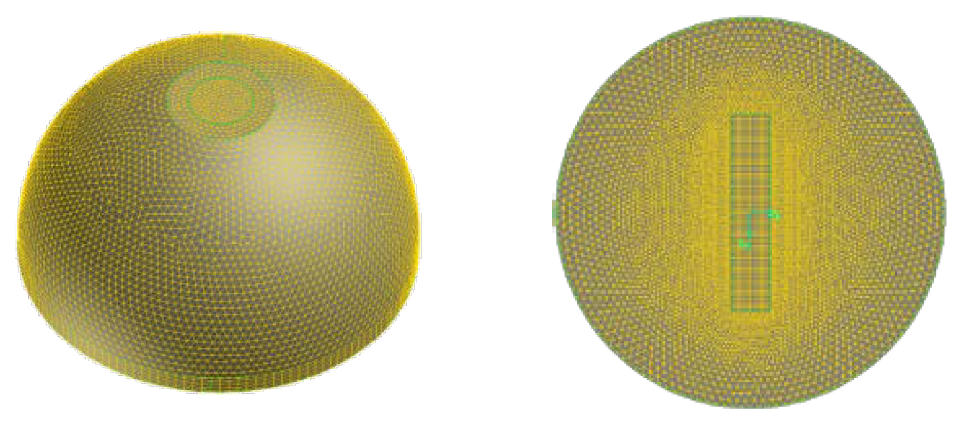
Define Scheme A as follows: axis length of the recovery hood is 1.2 m.
The model of the spherical recovery hood with an axis length of 1.2 m, and situated 40 mm distance from the outer plate, is established, and the technical parameters of existing industrial vacuum cleaners are combined to determine the simulated working conditions of the paint mist recovery hood, as shown in Table 1; the design appearance is as shown in Figure 6 and Figure 7.

3.2. Atomized Particle Splash Theory

The impact energy E is defined as:
E 2 = ρ V r 2 d p σ [ 1 min ( h 0 d p , 1 ) + δ b l d p ]
In the Equation, the following are defined:
ρ—liquid density, kg/m3;
Vr—the speed of movement of the droplet relative to the wall, i.e., Vr2 = (Vp − Vw)2, Vp and Vw represent the droplet-wall velocity, respectively, m/s;
Dp—droplet diameter, m;
σ—liquid surface tension, N/m;
h0—height of the liquid film on the wall, m;
δbl—avoid boundary layer height, which is defined as:
δ b l = d p R e
The Reynolds number Re in the above definition is defined as:
R e = ρ V r D μ
The impact energy is defined so that a liquid film is generated when the droplet undergoes splash, while the calculation results do not appear unphysical when the film thickness is 0.
It is generally believed that when the dimensionless impact energy is lower than 16, the stick method will be applied and the droplet velocity after collision will be set to the same magnitude as the wall velocity. In the spread model, the Wall-Jet model will be used to set the initial velocity and direction of the droplet.
If the wall temperature is higher than the liquid boiling point temperature and the impact energy of the droplet is lower than the critical impact energy (Ecrit), then the droplet will bounce back from the wall. In the case of rebound, the droplet rebound coefficient is calculated as shown in Equation (5).
f = 0.993 1.76 θ I + 1.56 θ I 2 0.49 θ I 3
where θI is the angle (radian) between the droplet and the wall when the droplet collides with the wall.
When the impact energy is higher than the critical impact energy (Ecrit = 57.7), then the particle will undergo splash.
When the droplet with higher energy collides with the wall, then the droplet will splash, and several new particles will be created. The properties of the newly created particles (diameter, velocity and direction) will be randomly selected from the distribution function obtained from the experiment. When the number of droplet splashes is 0, the splash calculation is turned off in the Lagrangian model. The diameters of the newly generated particles are sampled from a cumulative probability distribution function (CPDF), also referred to here as F. It comes from the experimental data obtained by Mundo, while satisfying the Weibull distribution function, for which Equation (6) is the equation of the distribution function.
f ( d ) = 2 d D 2 exp [ ( d D ) 2 ]
This equation represents the probability of a particle of diameter di appearing in the droplets produced by the splash, where D = dmax/√2, dmax is the diameter of the particle corresponding to the peak of this distribution function. To ensure that this particle does not produce unphysical results at high Weber numbers, the diameter distribution of the splash particles is shown below:
d max d 0 = max ( E c r i t 2 E 2 , 6.4 W e , 0.06 )
The second term on the right-hand side of the above equation describes the distribution of droplet diameters produced by colliding particles at low Weber numbers. At the same time, O’Rourke’s experimental studies have shown that for collisions at high energies, the minimum peak of the droplet diameter distribution function for splash generation is not less than 0.06. The Weber number is defined using the relative velocity and droplet diameter as follows:
W e = ρ V r 2 D σ
D in Equation (8) represents the droplet diameter. To be able to extract the particle diameter from the experimental data, a cumulative probability distribution function (CPDF) is required, and the cumulative function can be obtained by the following Equation (9).
F ( d ) = 1 exp [ d 2 D ]
The upper and lower limits of integration are 1 and 0, respectively, and the inverse of the above Equation yields an expression for the diameter of the droplet produced by a splash of sequence i:
d i = D ln ( 1 c i )
Once the diameter of the secondary droplet has been determined, the sampling probability of particles at that diameter can be calculated from the probability distribution function mentioned above to obtain the number of particles produced by the splash. To find the number of particles, it is also necessary to know the total number of particles produced by the splash, a value that can be obtained from the conservation of mass. Based on Mundo’s experimental data, the mass of the splash particles is a quadratic function of the collision energy E. The mass fraction ys of the splash droplets in the total droplet mass is calculated as the expression:
y s = { 1.8 × 10 4 ( E 2 E c r i t 2 ) ,   E c r i t 2 < E 2 < 7500 0.70 , E 2 > 7500
The researchers found that almost all typical liquid sprays produce impact energies greater than the upper limit of 7500, and so they almost always splash 70% of the total droplet mass. To obtain the number of total droplets, note the mass conservation relationship that the sum of the splash masses of all droplet packages is equal to the total mass of the splash, i.e.,
ρ π 6 N t o t n = 1 N p a r c e l s ( f n d n 3 ) = y s m 0
where m0 is the total mass of the parcel impacting the wall, then the total number of droplets touching the wall is:
N t o t = y s m 0 ρ π 6 n = 1 N p a r c e l s ( f n d n 3 )
The number of splash droplets in each droplet packet is then equal to the total number of droplets Ntot multiplied by the probability distribution function corresponding to the droplet diameter.
Once the number of splash particles is obtained, the splash velocity of the particles needs to be determined. While satisfying Mundo’s experimental data, the Weibull distribution function can be used as a probability distribution function for the normal velocity of the splash particles, with the specific probability density calculated as shown in Equation (14):
f ( V n i V n d ) = [ b v θ v ( v n i / v n d / θ v ) b v 1 ] exp [ ( v n i / v n d / θ v ) b v ]
The expressions for bv and θv in Equation (15) are shown as follows:
b v = { 2.1 , θ I 50 ° 1.1 + 0.02 θ I , θ I > 50 °
θ v = 0.158 e 0.017 θ I
In Equation (15), θI is the droplet collision angle. The expression for the tangential velocity is given in Equation (17), where θs is the bounce angle of the droplet produced by the splash, θs = 65.4 + 0.226θI.
V t i = V n i tan ( θ s )
The sum of the kinetic energy and surface energy of the droplet produced by the final splash should be less than the sum of the droplet energy before the collision, and the energy balance equation can be obtained as:
1 2 n = 1 N p a r c e l ( m i v i 2 ) + π n = 1 N p a r c e l ( N I d i 2 ) = 1 2 m d V d 2 ( m d V i 2 ) + π ( m d d i 2 ) E c r i t
where Ecrit is the critical energy of splash occurrence, to ensure energy conservation, the following correction parameters are used:
K = 1 2 m d V d 2 m i V i 2 + π ( N d d 2 ) E c r i t π i = 1 N p a r c e l ( N i d i 2 ) 1 2 i = 1 N p a r c e l ( m i V i 2 )
The modified expressions for the normal and tangential velocities of the secondary droplet are:
V n i = K V n i V t i = K V t i

3.3. Model Network Division

The x_t geometry model obtained in Solidworks was imported into Gambit and mixed meshing was carried out, i.e., the area near the spray fan was structurally meshed and the rest of the area was unstructured.
Considering the more intense atomization of the paint in the spray fan area and the high number of droplet particles, a rectangle of size 8 cm × 40 cm × 32 cm was created in Gambit and used to separate the recovery hood model, in order to establish the topological relationship between the two. The number of nodes on each side of the rectangle is then specified to ensure that the mesh sizes are similar in all directions and that the structural meshing is carried out.
After the internal rectangular area is meshed, the unstructured meshing of the external area of the rectangular body is completed by adjusting the number of nodes on the outer edge of the recycling hood model and controlling the distribution. The final obtained mesh model is shown in Figure 8. The number of this mesh is 381,214 and the worst mesh quality is 0.79, which can meet the calculation requirements.
In order to better demonstrate the internal situation of the recovery hood mesh, the mesh model imported into Fluent is displayed in two symmetry faces, and the sliced mesh on the corresponding face is shown in Figure 9.
In order to facilitate the statistics of the paint mist trajectory tracking results on each boundary in the subsequent numerical simulation of paint mist recovery, the definition of the boundary type needs to be completed before exporting the mesh model in Gambit. In order to facilitate the statistics of the paint mist information on the different boundaries in the subsequent numerical simulation, the air inlet surface is divided into two symmetrical parts about the yz plane, named the inlet surface and inlet-separated surface, respectively, and the scope and settings of each boundary are described later in the numerical simulation.

3.4. Numerical Simulation Settings

Using a negative suction pressure of −0.9 kPa as an example, a case study of numerical simulation of paint mist recovery using a single-layer spherical recovery hood mesh model in Fluent is presented, with the main steps as follows.
a.
In the General node, ensure that the size of the recovery hood mesh model is scaled to the correct size, check the mesh quality and set the solver and gravity terms. Since the atomization of paint is a transient process, the scheme type is selected as Transparent.
b.
The continuous phase model and discrete phase model are set up in the Models model node. It is important to note that the main settings for both the continuous and discrete phases in the paint mist recovery numerical simulation are the same as in the spraying numerical simulation section. The only difference between the two parts of the simulation is the calculation model and the type of boundaries and their parameter values. Figure 10 shows the interface for setting up the discrete phase model and some of the important parameters for the discrete phase settings are explained further here.
The options Interaction With Continuous Phase and Unsteady Particle Tracking are selected in the main DPM interface to couple the motion of the continuous phase air and discrete phase particles and to track the paint mist particles unsteadily.
After setting up the Tracking and Physical Models items at the bottom of the main DPM interface, click on Injections to set up the jet source and complete the definition of the flat fan blade atomisation model.
In Figure 10, the Injection type is selected as Flat-Fan Atomizer, i.e., the flat fan atomisation nozzle model, and the Particle Type is selected as Inert, i.e., inert particles.
The motion of these particles obeys the force balance Equation and the heating/cooling law, and they can be selected for all jet source models. In addition, Fluent also offers Massless, Droplet, Combusting and Multicomponent types of particles.
Of these, the Droplet type can only be selected if the heat transfer model is activated, which in addition to satisfying the force balance Equation and the heating/cooling law, further describes the evaporation and boiling of particles in Fluent with Law 2 and Law 3.
The Combusting type is applicable to solid particles and follows the same heating/cooling process as defined by the force balance Equation, Law 1, in addition to being controlled by the volatile precipitation and heterogeneous surface reaction mechanisms given by Law 4 and Law 5. As the effects of temperature and volatilisation are not considered in the numerical simulation of paint spraying and paint mist recovery, the particles are chosen as Inert types.
A brief description of the parameters and their significance is as follows.
(1)
Erosion/Accretion, Stochastic Collision, Coalescence and Breakup are selected in the Physical Models option box to simulate phenomena such as erosion/deposition, random collisions, merging and fragmentation during paint atomisation. The physical significance of the above options is described in detail in the spray atomisation simulation in Part 1 of the report.
For the Saffman Lift Force option, which focuses on sub-micron particles, the lift force of the droplet due to the difference in flow velocity between the two sides is simulated when the fluid velocity gradient is perpendicular to the droplet’s direction of motion.
Virtual Mass Force and Pressure Gradient Force are often used in combination and are recommended for cases where the density of the fluid is close to or exceeds the density of the particle (e.g., coupled motion of the fluid and bubble) to take into account the effects of the virtual mass force and pressure gradient terms in the calculation of the force balance of the particle.
The DEM Collision option is mainly used for the simulation of phenomena such as dust, coal ash and other solid particle erosion. Therefore, these options were not selected for the numerical simulation of spray atomisation and paint mist recovery in the report.
(2)
Spherical is selected in Drag Law, i.e., the particle is assumed to be smooth and spherical, and then the drag law is applied to the force balance calculation of the tracked particle. For spraying, assume that the particles ejected from the flat fan blade atomising nozzle are standard spherical before and after atomisation.
Activate the Breakup option and select the fragmentation model as the stochastic secondary fragmentation (SSD) model and set the value of the critical Weber number to 10.
(3)
Complete the specification of each boundary condition in the Boundary Conditions node. After importing the mesh model into Fluent, the software will automatically assign an ID number to each boundary in the basin. Based on the ID number of the boundary, the user can view the monitoring information on the boundary corresponding to each ID number from the console or the export file.
In Figure 11, the boundaries of the recycling hood model are shown colored according to the ID number after the Fluent model has been imported, the walls of the recycling hood are shown transparently for viewing purposes, and the definition names of the boundaries are given.
The type of each boundary is automatically given by default after the model is imported in Fluent and the user usually has to adjust the type of boundary and parameter settings according to the needs of the calculation.
For the paint mist recovery in this report, the inlet surface is directly connected to the atmosphere, so its boundary type can be set as pressure inlet; the suction surface adopts negative pressure recovery, accordingly the boundary type is set as pressure outlet, and the value of table pressure is set as relative negative pressure; after the kinetic energy of paint mist is consumed in the recovery hood and air coupling, it can be considered to be directly adsorbed after moving to the inner wall of the hood, so the boundary type of the recovery hood is set as Stational Wall, i.e., static wall. and the discrete phase property of the boundary is set as Trap, which means that particles will be trapped when they reach this boundary in the numerical simulation. Table 2 shows the correspondence between the ID number, name and setting properties of each boundary of the mesh model in the Fluent simulation.
Taking the inlet-separated boundary as an example, the specific settings of the continuous and discrete phase boundary properties of this boundary are described, as shown in Figure 12, with the currently set boundary highlighted in the right-hand graphical display area.
The numerical simulation of the paint mist recovery at a negative suction pressure of −0.9 kPa is used as an example. The gauge pressure on the suction surface is set to −900 pa, which means that the pressure there is below the standard atmospheric pressure of 900 Pa.
The monitoring information is set under the Monitors node, where the residual convergence accuracy is set to 5 × 10⁻⁴. To facilitate the prediction of whether the set value of the negative suction pressure is reasonable before the calculation is completed, the area-weighted average of the inlet and suction surfaces is set by Surface Monitor.
Definition of operating conditions: The pressure reference point is set on the intake surface to ensure that the pressure value on the intake surface is standard atmospheric pressure.
(4)
As the trajectory tracking of particles in airless spraying is a transient scheme type, the scheme method is selected as the PISO algorithm. Depending on the quality of the mesh, the Gaussian node-based or Gaussian cell-based spatial discretization method is selected. In this case, the spherical recovery cover is divided by a mixed mesh, and the presence of tetrahedral mesh makes the mesh quality relatively poor, so the Gaussian node-based discretization method is chosen here.
(5)
Set the monitoring information under the Monitors node, in which the residual convergence accuracy is set to 5 × 10⁻⁴. To facilitate the prediction of whether the setting of the negative suction pressure is reasonable before the calculation is completed, the area-weighted average of the inlet and suction surfaces is set in Surface Monitor.
(6)
As the inlet surface is separated into two parts, the scheme is initialised by selecting All-Zones in the Compute From drop-down menu, i.e., from the full domain. The initialisation from the pressure inlet boundary can also be selected. Both methods have little effect on the calculation, and only have an effect on the initial convergence rate of the calculation. Then, in the Run Calculation node, set the time step and the number of scheme steps to start the calculation.
For the spherical recovery hood in this chapter, its radius is 0.4 m, and the spraying simulation speed is 0.5 m/s. Therefore, after 0.8 s of calculation, the liquid film on the positive side of the x-axis has been steadily dragged out of the calculation domain, and the paint mist recovery and liquid film deposition inside the hood have remained relatively stable. In the case simulation, the time step at the beginning of calculation is 0.0002 s. To improve the calculation efficiency, the time step can be increased after the calculation converges and stabilizes.
As shown in Figure 13, check the Filter item and set the filter range for the particle retention time in the Particle Filter Attributions pop-up.
In addition, uncheck the Auto Range option, set the particle diameter range from 0 to 100 μm, select Draw Mesh, and display each boundary transparently by the method described above.
As can be seen from the graphical display on the right, the diameter of the particles emitted from the virtual nozzle decreases as the atomization progresses, with the majority of particles above 60 μm in diameter before hitting the wall.
The splash particles after impact are divided into two parts: firstly, large diameter particles with a large splash angle and secondly, smaller diameter particles with a small splash angle, essentially spreading outwards against the outer hull plate, which are more numerous
Similarly, the velocity range of the particles was set at 0–100 m/s and 0–10 m/s, respectively, and the diameter distribution of the paint mist with a retention time of 0–0.03 s was displayed to visually compare the velocities of the paint mist before and after the wall impact and the two types of splash mist; the results are shown in Figure 14.
As can be seen in Figure 14a, the velocity of the paint particles is basically above 40 m/s before the wall impact and within 15 m/s after the wall impact.
The velocity range of the splash paint mist is further shown in Figure 14b and can be seen in different views. It can be seen that the velocities of both types of splash paint mist are roughly within 9 m/s, but the first type of large splash paint mist has a wider range of velocity variation, with a small number of particles reaching velocities of 10 m/s or more.
The display settings for the velocity vectors are created in Fluent using Surface > Plane Surface, creating two auxiliary surfaces in the xz plane (vertical spray fan) and yz plane (spray fan). To display the airflow in these two auxiliary surfaces, open the vector settings window in the Results node on the right hand side of the model tree using the Results > Graphics > Vectors command.
Figure 15 shows the velocity vector within the sprayed sector, setting the values of scale and skip to 7 and 2 to scale and thin the velocity vector, respectively. The maximum velocity of the air within this surface is 41.1 m/s and the high speed zone is located near the intake surface. The velocity vector gyratory vortex is marked in the red wireframe and analyzed; the reason for this is that near the outer hull plate, a high proportion of the small splash angle paint mist of the second type drives the surrounding air movement, generating convection with the air drawn in from the inlet surface and forming a velocity vortex within the spraying sector.
It can be seen that the velocity swirl on the y-axis positive side of the spraying fan has a dampening effect on the diffusion of the particles on that side, hence the thicker film at the edge of the y-axis positive side in the liquid film thickness cloud in Figure 15.
Figure 16 shows the velocity vector perpendicular to the spraying fan, i.e., in the xz plane, and it can be seen that the air phase velocity vector has a long parallel expansion zone close to the surface of the shipboard, which is driven by the small splash angle of the second type of paint particles, indicating that the spread of paint splashes along the direction perpendicular to the spraying fan is more pronounced.
The total kinetic energy of the splash mist in this direction is higher, so that the air flow driven by the second type of splash mist in convection with the air drawn in at the inlet surface creates an air vortex closer to the wall of the recovery hood than the air vortex on the spray fan.
To further visualise the gas movement within the recovery hood, this was observed by creating an auxiliary line on the inlet surface and showing the flow lines through the grid nodes on this auxiliary line.
The Iso-Surface settings panel is opened via the Surface > Iso-Surface command, the two inlet boundaries are selected in From Surfaces on the right hand side and the Iso-Values of the z-directional coordinates are set to 0.02 m, i.e., the z = 0.02 m plane is used to find the intersection line with the inlet surface, thus creating the central auxiliary line inlet of the inlet surface-z-0.02 m.
With the Results > Graphics > Pathlines command, open the settings panel for the display of the gas traces, select velocity as the display variable, select the previously created auxiliary line inlet-z-0.02 m in the Release From Surfaces option and set the colour of the auxiliary line to orange to differentiate the display.
Figure 17 shows the gas traces on the auxiliary line through the inlet surface. It can be seen that most of the traces are created on the inlet surface and then flow out of the suction surface after being rolled over, most of the traces have low velocities and a few appear to accelerate when coupled by the high speed paint particles in the spraying sector.
By using the Results > Reports > Surface Integrals command and selecting the Report Type as Area-Weighted Average in the pop-up panel, the area-weighted average of the flow velocity on the two inlet boundaries, i.e., the average velocity, can be output, and similarly, the average velocity value on the suction surface can be output.
The average velocities on the inlet and suction surfaces are 3.93 m/s and 36.53 m/s, respectively, which gives a ratio of 9.29 between the average velocities on the suction and inlet surfaces; however, the ratio between the area of the inlet and suction surfaces is 7.57 because the velocities required in the flow conservation equation are vector projections of the velocities on the cross section. The area-weighted variables on the inlet and suction surfaces are set to Radial Velocity and z Velocity, respectively, which are the velocity components normal to the cross section. By changing the Report Type to Volume Flow Rate, the volume flow rates on the inlet and suction surfaces are output directly to the console and the Net value is the superposition of the volume flow rates on the inlet and suction surfaces with a magnitude of 107, further verifying the conservation of flow on the two ventilation surfaces.
Select Summary for the Report Type in the Particle Track panel and refer to the diagram for the rest of the options to output the statistics of the paint mist track information on each boundary at the current moment to the console.
ID number 6 corresponds to the inlet boundary and ID number 5 to the inlet-separated boundary. The fate of the trajectory statistics on both boundaries is “Escaped”, i.e., the particle disappears from the calculation domain after passing through the boundary and the trajectory tracking is terminated.
The reason for the large difference in paint mist mass accumulation between the two boundaries is that the discrete phase boundary wallfilm of the sprayed wall surface (ship) in the simulation is a combination of four collision modes: adhesion, bouncing, splashing and stretching; the particles in the deposited liquid film move with the outer hull plate in an aggregated state.
Here, the total mass of paint mist counted on each boundary is subtracted from the mass of paint mist counted on the inlet-separated surface. Since the two inlet surfaces are symmetrically distributed and have the same area, the mass of pure splash particles on the inlet surface is regarded as the theoretical mass of splash paint mist on the inlet-separated boundary, and the total mass of paint mist counted on each boundary is obtained after removing the statistical mass of deposited liquid film particles.
After correction, the total mass of paint mist on each boundary in this case is 3.5939 × 10⁻³ kg, which corresponds to the fate of the paint mist can be divided into three categories: escape to the atmosphere via the inlet surface, adhesion to the inner wall of the recovery hood and absorption via the suction surface, from which the information on the recovery of paint mist from the spherical recovery hood under this recovery pressure condition can be calculated as shown in Table 3.
The total mass of paint mist whose final trajectory has been determined at this point on each boundary is 8.807 × 10⁻³ kg, which, when added to the total mass of particles with undetermined trajectories in the calculation domain, is the total spray mass of the incident source, which has a value of 2.7097 × 10⁻² kg.
The theoretical spray mass and the simulated spray mass of the incident source are basically the same, and minor differences may be due to rounding or truncation errors in the software calculation, etc.
At the current moment, the total mass of the splashing part of paint mist on each boundary after correction is 3.5939 × 10⁻³ kg, and after excluding the mass of this part of the paint mist, the ratio of the remaining mass and the theoretical spray mass is calculation to obtain the actual utilization rate of the paint under the current negative suction pressure is 86.73%.
Similarly, post-processing the simulation results at 1.2 s gives the information on paint mist recovery from the spherical recovery hood at this time, as shown in Table 4, where the actual paint utilization rate is 85.84%. Comparing the statistics for the 1.0 s and 1.2 s paint mist recovery simulations in Table 4, it can be seen that the average air velocity on the inlet and suction surfaces of the hood has stabilized, and the percentage of fugitive, adherent and absorbed paint mist has remained more or less the same, so it can be assumed that the results of the recovery simulation have remained stable at this point.

4. Simulation Analysis of the Motion Characteristics of Static Spray Gun Paint Mist Particles

4.1. Analysis of the Diameter and Velocity of the Paint Mist Particles Moving by the Spray Gun under the Action of the Non-Vacuum Recovery Air Flow Field

The paint mist particles under the action of the vacuum-free recovery air flow field and the spray gun are not moving are used as the research object to study the diameter distribution and velocity distribution of the paint mist particles. The simulation setting spraying pressure is 16 MPa and spraying distance is 30 mm. The simulation results are shown in Figure 18 and Figure 19.
According to the distribution of paint mist on the cross-section, paint mist can be divided into three categories according to the direction of escape: The first type of paint mist has a distribution range of 0~0.01 m, which shows that the speed and diameter of this type of paint mist are the smallest. According to statistics, the average kinetic energy of paint fog is 4.3 × 10⁻⁸ J; the distribution range of the second type of paint fog is 0.01~0.025 m, and the number of droplets of this type of paint fog is the largest. At the same time, the Sauter diameter and speed of the paint fog are relatively large. This part of the paint mist is the paint mist generated after the paint collides with the outer panel, and its average kinetic energy reaches 1.50 × 10⁻⁷ J, so this part of the paint mist is the key and difficult point of recycling; the third type of paint mist has a distribution range of more than 0.25 m. Sauter has the largest diameter, but the speed is not high. The statistics show that the kinetic energy of this part of the paint mist is about 1.47 × 10⁻⁷ J, which is similar to the kinetic energy of the paint mist in the middle area. In summary, the paint mist that is more difficult to recover is the middle layer paint mist.
From the spatial distribution of the paint mist, the distribution of the paint mist shows the offset along the direction of gravity, especially the diameter and speed of the smaller paint mist. The farthest movement has moved along the direction of gravity to the position of about 0.4 m from the spraying axis, while the fart of the upward splash only moves up to 0.2 m, which shows that gravity has a direct impact on the movement of the paint mist.

4.2. Analysis of the Range of Motion of Paint Mist Particles Moving by Spray Gun under the Action of the Airflow Field without Vacuum Recovery

Currently, shipyards use a “zig-zag” spraying process, and in order to avoid localised unevenness caused by the gun pre-extruding paint prior to spraying, the gun motion control command will be given priority in the control system before the gun firing command is given. The partial blanking of the coating caused by this operation will be followed up manually. The stage is therefore at the start-up spraying stage, so the area of manual make-up coating is not large enough to affect the overall robot efficiency.
Based on the process analysis of manual coating in shipyards, the speed of the robot movement and recovery hood coupling can be set at 0.5 m/s.
In order to study the range of motion of the paint mist in the free spraying process, the calculated flow field size was specified as 3 × 2 × 1.5 m, and the nozzle was sprayed in the middle of the flow field at a spraying speed of 0.5 m/s with a spraying pressure of 16 MPa, Figure 20 is a schematic diagram of the trajectory of the paint mist at different moments.
After the collision with the outer plate, the paint is seen to splash in all directions. The paint mist is divided into two categories according to the trajectory of the droplets: the first category of paint mist has a larger angle between the spattering direction and the outer plate of the hull, and its trajectory is deflected earlier because the upward velocity component is larger; the second category of paint mist is basically attached to the outer plate of the hull, and its deflection occurs more laggingly under the action of air.
At about 0.4 s of spraying time, the first type of paint mist had already deflected, while the direction of the second type of paint mist basically did not change. At 0.8 s, the second type of mist also started to deflect. At about 1.2 s of spraying time, the trajectory of the paint mist continued to develop, except that the direction of the paint mist changed further to the rear, and the height of its trajectory was gradually increasing. When the spraying time reaches 1.6 s, it can be found that the paint mist basically does not move forward, and the trajectory of the paint mist flips significantly, and the highest point of the trajectory reaches about 0.7 m. It can be considered that when the spraying time reaches 1.6 s, the paint mist spraying trajectory has reached the farthest distance of the movement, i.e., about 1.4 m. Figure 21 draws 1.6 s moment in the spraying flow field of the air phase velocity cloud map.
A comparison of the velocity cloud and the paint mist trajectory shows that the two remain basically the same, where the airflow in the direction of height is less affected by the spraying. The velocity of the air phase near the surface of the outer plate near the spraying area is the fastest, and the velocity of the air phase decreases rapidly as the distance increases. The results of the airflow velocity variation on the surface of the extracted hull are shown in Figure 22.
As shown in Figure 22, the air phase velocity rises rapidly near the spraying area, and gradually decreases and drops to the lowest point at 1.3 m from the nozzle after leaving the spraying area, followed by a small increase in velocity, which indicates that the air velocity turns at 1.3 m.
Analysis of the simulation results of the paint mist movement range shows that the height of the paint mist in the middle range is basically maintained below 30 mm before deflection occurs, so the the paint mist in this area is easy to escape from the recovery hood; while the higher range of paint mist movement trajectory gradually away from the outer plate, and the distribution range is higher than 35 mm, which means it is more easily affected by the air phase deflection; so it is difficult to escape from the recovery hood into the air surface, and the mist will eventually be deposited in the hood. Therefore, the spacing between the recovery hood and the outer plate is initially taken as 40 mm, focusing on the recovery of the middle part of the paint mist.

5. Analysis and Optimization of Vacuum Recovery Effect

5.1. Analysis of Paint Mist Recovery Effect

As shown in Figure 23, the wind speed of the suction surface of the recovery hood increases gradually with the increase in the negative pressure of suction, and the average speed of the inlet of the recovery hood increases from 3.2 m/s to 5.2 m/s.
According to the calculation, the wind speed of the suction surface of the recovery hood can be calculated to increase from 27 to 45.3 m/s. The average wind speed of the inlet surface of the recovery hood at 0.9 kPa is the same as the air phase flow speed at the free spraying state.
As the power of the suction pump increases, the negative pressure at the outlet of the recovery hood gradually increases, leading to an increase in the speed of airflow at the inlet surface, and the air volume of the suction pump should reach 1700~2800 m3/h at the corresponding pressure according to the calculation. The trajectory of the paint mist in the recovery hood will be different under the influence of different inlet airflow, and the trajectory of the paint mist with time is shown in Figure 24.
As shown in Figure 24, the paint mist can be divided into three categories: firstly, it escapes from the air inlet surface along the original direction; secondly, it adheres to the paint mist recovery hood after changing direction; thirdly, it is sucked into the suction pipe under the action of air phase.
In order to evaluate the efficiency of the recovery hood, the efficiency of the recovery system η is defined as shown in Equation (21).
η = ( 1 m 1 m 1 + k 1 m 2 + k 2 m 3 ) × 100 %
where m1 is the paint mist escape mass, kg, m2 is the paint mist adhesion mass, kg, and m3 is the paint mist absorption mass, kg. The coefficients k1 and k2 reflect the influence of the paint mist deposited on the recovery hood and absorbed by the recovery pump on the efficiency of the paint mist recovery, in which the coefficient k2 should be larger than k1 in order to enhance the influence of the absorbed paint mist on the efficiency of the paint mist recovery. In this paper, for the sake of simplicity, the influence of both on the recovery efficiency is not considered and is taken as 1.
After the statistics of the escape of paint mist at different pressures, as shown in Table 5, it can be seen that the recovery efficiency of paint increases with the increase in the suction pressure, from 27.2% at 0.6 kPa negative pressure to 57.4% at 1.5 kPa. However, although the average velocity of the inlet surface has reached 4 m/s at 0.9 kPa, some paint mist still escapes because the velocity of some paint droplets is higher than the velocity of the air phase. In order to solve this problem, the current design of the recovery hood has the defect of low efficiency and needs to be optimized and improved for its problems.

5.2. Problems of the Recovery Hood

(1)
The first task in optimising the recovery hood requires an understanding of how the paint mist escapes and its distribution characteristics within the hood. Figure 25 calculates the distribution of paint mist droplets within the recovery hood.
Inside the recovery hood, the paint mist is more densely distributed in the direction perpendicular to the spraying fan (x-axis direction), and the distribution of paint mist parallel to the spraying fan is very small. This indicates that the airflow is also affected by the inlet surface, and the kinetic energy of the paint mist is greater in the direction perpendicular to the spraying fan, which makes it more difficult to deflect the direction. It is also seen that the paint mist is most dense in the area near the inlet surface in the direction of the vertical spraying fan, which indicates that the paint mist is mainly escaped from here. With the increase in pressure, the vertical spraying fan direction paint mist aggregation degree is reduced, indicating that the proportion of paint mist under the action of airflow to the edge of the recovery hood inlet surface is reduced, and the effect of paint mist recovery is improved.
(2)
Distribution of paint mist on the surface of the recovery hood
According to the statistics of paint mist escape, the amount of paint mist deposited on the surface of the recovery hood gradually increases with the increase in suction pressure. The cloud diagram of paint mist deposited on the recovery hood under different pressure is shown in Figure 26.
The distribution of paint mist on the surface of the recovery hood is significantly different in two directions. In the direction perpendicular to the spraying fan, the distribution of paint mist on the recovery hood is more concentrated, while the distribution of paint mist on the recovery hood in the direction of the spraying fan is very small. With the increase in suction pressure, the paint mist enrichment area suction surface movement, near the recovery hood and above the paint mist deposition, gradually increases.
(3)
Intake surface fugitive area distribution
The fugitive distribution cloud of paint mist in the air inlet surface is shown in Figure 27.
It can be seen that the escape area of the paint mist in the inlet surface is mainly concentrated in the vertical direction of the spraying fan, and the width of the distribution and the width of the spraying fan remains basically the same. With the increase in suction pressure, the paint mist escape area width gradually narrowed and the escape density of the paint mist is reduced.

5.3. Recovery Hood Improvement

Since the kinetic energy of the paint mist is higher in the direction perpendicular to the fan surface, the paint mist mainly escapes from the recovery hood in this direction. In order to solve this problem, without changing the paint mist recovery parameters, the paint mist recovery hood is modified into an ellipsoidal shape, and in order to increase the influence of the paint mist in the x-axis direction, the suction pipe is split into two suction pipes arranged in front of and behind the spraying fan surface.
Define Scheme B as follows: axis length of the recovery hood is 1.6 m.
Define Scheme C as follows: axis length of the recovery hood is 2.0 m.
The bottom axis length of the recovery hood, that is, the direction of the vertical spraying fan, is increased to 1.6 m and 2.0 m, respectively, and the shape of the improved paint mist recovery hood is shown in Figure 28.
Figure 29 shows the liquid film thickness cloud on the outer hull plate at 1.2 s of the simulation. It can be seen that the increase in step size makes the liquid film thickness cloud less homogeneous, but it has no influence on the proportion calculation of monitoring paint fog on each boundary.
It can be seen from Figure 30 that, as the spraying time increases, the film is relatively homogeneous away from the current spraying sector, probably due to the second type of small splash angle paint mist driven by the air diffusion along the outer hull plate to both sides of the spraying sector, and then the blowing effect, making the deposited film more homogeneous away from the current spraying sector.
As the major axis length of paint mist recovery cover changes, the average wind speed on the intake surface and suction surface of the recovery cover will change under the same suction pressure. The change of wind speed on different types of recovery cover with suction pressure is shown in Figure 30.
Using the same simulation method as that of Scheme A with a diameter of 1.2 m, the simulations of Scheme B with a diameter of 1.6 m and Scheme C with a diameter of 2.0 m are carried out. The simulation description is omitted, and the paint mist escape data are shown in Table 6.
Compared with the improved hood, the speed of the suction surface is basically the same under the same suction pressure, but the wind speed of the inlet surface decreases gradually with the increase in the length of the hood, which will have a negative impact on the effect of paint mist recovery. The calculation of the improved recovery hood paint mist escape is shown in Table 6.
It can be seen that by changing the length of the diameter of the recovery hood, the air velocity at the inlet side of the hood will be reduced, but an increase in the movement distance of the paint mist can also significantly improve the efficiency of paint mist recovery. When the diameter of the hood is lengthened from 0.6 m to 1 m, the efficiency of paint mist recovery increases by about 25% at the same air volume. When the suction surface pressure reaches 1.5 kPa, the recovery efficiency of paint mist reaches 83.4%, which can significantly reduce the environmental impact of paint mist escaping from the spraying process and meet the needs of engineering applications.
In summary, the efficiency of the paint mist recovery hood can be significantly improved by increasing the length of the semi-long axis of the hood perpendicular to the direction of the spraying fan and by reasonably distributing the number and location of the suction surfaces.

6. Conclusions

In this paper, we design a kind of negative pressure vacuum recovery hood, arranged at the front of the spray gun nozzle, to address the paint mist pollution problem of robot spraying on the outer plate of the ship, and we arrange the nozzle at the center of the recovery hood. Three vacuum recovery hood schemes are designed as follows: Scheme A, a hemispherical recovery hood with a diameter of 1.2 m; Scheme B, with a diameter of 1.6 m; Scheme C, with a diameter of 2.0 m. The recovery vacuum suction holes of the three recovery hoods are arranged differently. Firstly, a mathematical model of the spraying jet for the case of 0.48 mm diameter nozzle was established, and the established nozzle jet flow field model was verified to be feasible through case simulation analysis and experimental comparison. Secondly, the focus is on Scheme A as a case, with a detailed simulation process discussion and analysis; through the Scheme A simulation process it was found that the air velocity at the inlet surface and the kinetic energy of the paint mist had a large impact on the simulation effect, therefore, it is necessary to try to further improve the structure of the recovery hood. Finally, the further simulation analysis of Scheme B and Scheme C shows that Scheme C > Scheme B > Scheme A in terms of the paint mist recovery effect.
The simulation process of Scheme A found that the vacuum recovery pressure and the size of the recovery hood have a greater impact on the paint mist recovery effect, and the direct factors affecting the paint mist recovery effect are the wind speed on the inlet surface and the kinetic energy of the paint mist, which has a higher impact on kinetic energy in the direction of the vertical spraying jet fan, and therefore, the paint mist recovery efficiency is also lower.
Further proposed Scheme B and Scheme C simulation analysis process found that when the paint mist recovery hood axis length of 1.6 m was lengthened to 2.0 m, the paint mist recovery efficiency in the same air volume increased by about 25%. When the suction surface pressure reaches 1.5 kPa, the recovery efficiency of paint mist reaches 83.4%, which can significantly reduce the impact of paint mist escaping from the spraying process and into the environment, and the effect of the paint mist recovery is remarkable.
The surface spraying area of a large ship is very wide, about 300 m long fore and aft and about 40 m high, about 90% of the ship surface is straight, and the remaining bow, stern and bottom curves are very complex, but since the robot operation width is only about 1 m, the robot can basically be equivalent to an operation point and also achieve partial operation. Therefore, in this study, it is feasible to equate the surface of the spraying object to a straight surface, so the robot spraying actuator paint mist recovery simulation, in 90% of the ship surface area, has validity.
The large ship surface spraying area is very wide, about 300 m long fore and aft, and about 40 m high; about 90% of the ship surface is straight, and the remaining bow, stern and bottom curves are very complex, but since the robot operating width is only about 1 m, the robot can basically be equivalent to an operation point and also achieve partial operation. Therefore, in this study, it is feasible to equate the surface of the spraying object as a straight surface, so the robot-spraying actuator paint mist recovery simulation, within 90% of the ship’s surface area, has validity.
It is evident from the research in this paper that the use of Scheme C as a recycling agent for automatic spray paint mist in shipyards is more suitable for the recovery of paint mist, which provides a theoretical solution for the implementation of paint mist anti-fouling in shipyards as soon as possible.

Author Contributions

The manuscript is written through contributions of all authors. Conceptualization, Z.Y.; methodology, Z.Y.; software, B.F. and T.T.; validation, B.F.; formal analysis, Z.Y. and K.L.; investigation, T.T.; resources, Z.Y.; data curation, Z.Y.; writing—original draft preparation, S.M.; writing—review and editing, S.M.; supervision, Z.Y.; project administration, Z.Y.; funding acquisition, Z.Y. All authors have read and agreed to the published version of the manuscript.

Funding

This work was supported by the Projects Funded by the Central Government to Guide Local Scientific and Technological Development (Grant No. 2021JH6/10500156) and the Program Funded by Liaoning Province Education Administration (Grant No. 100920202037).

Institutional Review Board Statement

Not applicable.

Informed Consent Statement

Not applicable.

Data Availability Statement

Not applicable.

Conflicts of Interest

The authors declare no conflict of interest.

References

  1. Buketov, A.; Maruschak, P.; Sapronov, O.; Zinchenko, D.; Yatsyuk, V.; Panin, S. Enhancing Performance Characteristics of Equipment of Sea and River Transport by Using Epoxy Composites. Transport 2016, 31, 333–342. [Google Scholar] [CrossRef] [Green Version]
  2. Lin, Y.; Yi, Z.Y.; Li, Y.P. Large Spraying Robots for Ship Shell Plate in Dock. Robot 2018, 40, 115–127. [Google Scholar]
  3. Hao, X.Y.; Tian, L. Analysis on Clean Production in Environmental Impact Assessement of Shipping Business. Ship Eng. 2013, 35, 108–112. [Google Scholar]
  4. Yi, Z.; Song, C.; Zhang, G.; Tong, T.; Ma, G.; Wu, D. Microstructure and Wear Property of ZrO2-Added NiCrAlY Prepared by Ultrasonic-Assisted Direct Laser Deposition. Materials 2021, 14, 5785. [Google Scholar] [CrossRef] [PubMed]
  5. Lin, Y.; Yi, Z.Y.; Li, Y.P. Ship Outer Plate Drags Feed and Coating Cloud Recovery Protection Casing System of Formula of Scribbling Robot. Patent CN2016212257853, 5 November 2016. [Google Scholar]
  6. Sanghvi, H.; Massingill, J.L. Recycling paint overspray. J. Coat. Technol. 2002, 74, 143–145. [Google Scholar] [CrossRef]
  7. William, B.; Tisko, E.L.; Charles, H.R. Method for Removing and Recovering Paint Overspray in a Water Wash Spray Booth. Patent CA2140525, 3 February 1994. [Google Scholar]
  8. Buketov, A.; Smetankin, S.; Maruschak, P.; Yurenin, K.; Sapronov, O.; Matvyeyev, V.; Menou, A. New Black-Filled Epoxy Coatings for Repairing Surface of Equipment of Marine Ships. Transport 2020, 35, 679–690. [Google Scholar] [CrossRef]
  9. Savkiv, V.; Mykhailyshyn, R.; Maruschak, P.; Kyrylovych, V.; Duchon, F.; Chovanec, Ľ. Gripping Devices of Industrial Robots for Manipulating Offset Dish Antenna Billets and Controlling Their Shape. Transport 2021, 36, 63–74. [Google Scholar] [CrossRef]
  10. Stankiewicz, A.; Zielińska, K. Self-Healing Mechanisms in Smart Protective Coatings. In Applications in Corrosion Protection, 1st ed.; Saji, V.S., Ed.; CRC Press: Boca Raton, FL, USA, 2021; pp. 131–156. [Google Scholar]
  11. Zhao, A.W.; Yin, X.F. Research on application of new type dry paint mist separation device. Shanghai Coat. 2012, 50, 17–19. [Google Scholar]
  12. Yin, C.M. Dissertation of Applying Waste Gas Treatment and Heating System in Automobile Coating Workshop. Moder Paint Finish. 2011, 14, 45–47. [Google Scholar]
  13. Fan, S.Y.; Tang, J.W. On the Processing Technology of Ship Coating’s Environmental Pollutions. Ship Ocean Eng. 2008, 37, 36–38. [Google Scholar]
  14. Li, S.H.; Wang, T.Y.; Song, Y. Numerical Simulation of Electrostatic Precipitator’s Oblique Flow Effect on Dust Particle Sedimentation. Chem. Mach. 2015, 2, 220–224. [Google Scholar]
  15. Shao, Z.H.; Wei, B.L.; Ye, Z.P. Treatment of exhaust gas from spray paint process with plasma-photocatalytic method. J. Zhejiang Univ. (Eng. Sci.) 2014, 48, 1127–1131. [Google Scholar]
  16. Song, J.F.; Li, L.Q.; Yao, X.L. Characteristics of activated carbon modified by composite oxidation and its adsorption capacity for toluene. J. Cent. South Univ. (Sci. Technol.) 2014, 45, 1732–1739. [Google Scholar]
  17. Lin, Y.; Yi, Z.Y.; Li, Y.P. Ship Outer Plate Climbs Wall and Drags Formula of Scribbling Robot. Patent CN201621225810, 15 November 2016. [Google Scholar]
  18. Yi, Z.Y.; Mi, S.Y.; Tong, T.Q.; Li, K.; Feng, B.X.; Li, B.; Lin, Y. Simulation analysis on the jet flow field of a single nozzle spraying for a large ship outer panel coating robot. Coatings, under review.
Figure 1. Current situation of painting workers in Chinese shipyards.
Coatings 12 00450 g001
Figure 2. Chinese shipyard painters work at height to paint up-close.
Coatings 12 00450 g002
Figure 3. Current status of painting process in Chinese shipyards.
Coatings 12 00450 g003aCoatings 12 00450 g003b
Figure 4. Proposed design of paint mist-recoverable painting robot: (a) Wall-climbing robot carrier for spraying equipment; (b) Complete coating wall climbing system: 1. paint mist shield; 2. combined spray gun inside the paint mist shield; 3. reciprocating paint mist shield; 4. temperature, humidity, air pressure and wind speed sensor unit; 5. flexible hinge connection joint; 6. safety anti-fall fast suction unit; 7. feed tube and vacuum recovery tube; 8. vision camera; 9. ultrasonic paint film thickness detection module; 10. vision of the wall crawling robot body; 11. automatic traction of the feed and vacuum recovery mini container; 12. self-priming material drum.
Coatings 12 00450 g004
Figure 5. Particle strokes for paint spraying by spraying robots.
Coatings 12 00450 g005
Figure 6. Spherical recovery cover.
Coatings 12 00450 g006
Figure 7. Schematic diagram of painting principle (with cover).
Coatings 12 00450 g007
Figure 8. The appearance of the single-layer spherical recycling hood model after meshing is completed.
Coatings 12 00450 g008
Figure 9. Mesh slices in the symmetry plane of the single-layer spherical recycling hood are shown: (a) xz plane; (b) yz plane.
Coatings 12 00450 g009
Figure 10. Condition setting for inlet-separated boundary of single-layer spherical recovery cover.
Coatings 12 00450 g010
Figure 11. List display of boundary conditions in the basin.
Coatings 12 00450 g011
Figure 12. Condition setting for inlet-separated boundaries of single-layer spherical recovery hoods.
Coatings 12 00450 g012
Figure 13. Display setting of particle diameter distribution of paint mist within 0~0.03 s of retention time.
Coatings 12 00450 g013
Figure 14. Display of the distribution of the velocity of paint mist particles within 0–0.03 s of the retention time: (a) display range 0–100 m/s; (b) display range 0–10 m/s.
Coatings 12 00450 g014
Figure 15. Display of the speed vector on the sprayed sector.
Coatings 12 00450 g015
Figure 16. Vector diagram of air velocity in a vertical spraying sector.
Coatings 12 00450 g016
Figure 17. Gas traces flowing over the auxiliary line.
Coatings 12 00450 g017
Figure 18. Statistics of the paint mist diameter and velocity: (a) Droplet diameter statistics; (b) Droplet velocity statistics.
Coatings 12 00450 g018
Figure 19. Distribution characteristic of the paint mist: (a) paint mist diameter distribution; (b) paint mist velocity distribution.
Coatings 12 00450 g019
Figure 20. Motion trajectory at different times: (a) 0.4 s; (b) 0.8 s; (c) 1.2 s; (d) 1.6 s.
Coatings 12 00450 g020
Figure 21. Time 1.6 s contour of the air velocity.
Coatings 12 00450 g021
Figure 22. Velocity change at the hull surface.
Coatings 12 00450 g022
Figure 23. Motion trajectory of the paint mist in different inhale pressure.
Coatings 12 00450 g023aCoatings 12 00450 g023b
Figure 24. Relation between inhale pressure and the air velocity.
Coatings 12 00450 g024
Figure 25. Distribution of the paint mist in recovery cover: (a) 0.6 kPa; (b) 0.9 kPa; (c) 1.2 kPa; (d) 1.5 kPa.
Coatings 12 00450 g025
Figure 26. Mist deposition distribution on the cover: (a) 0.6 kPa; (b) 0.9 kPa; (c) 1.2 kPa; (d) 1.5 kPa.
Coatings 12 00450 g026
Figure 27. Mist escape distribution on the intake surface: (a) 0.6 kPa; (b) 0.9 kPa; (c) 1.2 kPa; (d) 1.5 kPa.
Coatings 12 00450 g027
Figure 28. Improved recovery cover: (a) axis length 1.6 m; (b) axis length 2.0 m.
Coatings 12 00450 g028
Figure 29. Liquid film thickness clouds for an ultra-large ellipsoidal recovery hood.
Coatings 12 00450 g029
Figure 30. Relation between inhale pressure and the air velocity.
Coatings 12 00450 g030
Table 1. Cases of the recovery cover.
ParametersPerformance
Recovery hood diameter/m1.2
Suction hole area/m20.0176
Distance of recovery hood from the wall/mm40
Suction force/kPa0.6~1.5
Nozzle diameter0.48 mm
Nozzle structurefan-shaped
Critical flow Reynolds number/mm8000~10,000
Paint attribute density/kg/m31320
Dynamic viscosity/kg(ms)10.275
Pressure range/MPa6~20
Jet distance/m0.01~0.025
Table 2. Description of the corresponding type of each boundary in the mesh model.
IDBoundary NameTypeGeneral SettingsDPM Boundary Settings
3ShipWallMoving WallWallfilm
4WallWallStationary WallTrap
5Inlet-SeparatedPressure-Inlet0 paEscape
6InletPressure-Inlet0 paEscape
7OutletPressure-OutletRecovery PressureEscape
Table 3. Statistics on the recovery information of the spherical recovery hood at a negative inspiratory pressure of −0.9 kPa at 1.0 s.
Pvw1w2w3VinVoutQairηrηu
−0.9 kPa14.88%45.72%39.40%3.9336.5−0.3826 m3/s85.12%86.73%
Table 4. Statistics on the recovery of the spherical recovery hood at a negative inspiratory pressure of −0.9 kPa at 1.2 s.
Prw1w2w3VinVoutQairηrηu
−0.9 kPa13.92%47.35%38.72%3.9436.60.3834 m3/s86.08%85.84%
Table 5. Percentages of the escaping mist in different face.
P1/kPaFugitive ShareDeposition RatioAbsorption RatioRecycling Efficiency
0.672.7%16.43%10.87%27.2%
0.962.3%19.56%18.14%37.3%
1.253.2%19.92%27.52%46.8%
1.542.6%21.15%37.5%57.4%
Table 6. Percentages of the escaping mist in the improved cover.
Suction Pressure/kPaFugitive ShareDeposition RatioAbsorption RatioRecovery Efficiency
1.6 m0.648.3%37.7%14.0%51.7%
0.940.6%41.8%17.6%59.4%
1.229.0%46.2%30.8%71.0%
1.523.7%40.9%35.4%76.3%
2.0 m0.639.6%43.0%17.4%60.4%
0.934.1%40.0%25.9%65.9%
1.223.5%38.9%37.6%76.5%
1.516.6%44.9%38.5%83.4%
Publisher’s Note: MDPI stays neutral with regard to jurisdictional claims in published maps and institutional affiliations.

