Article

Microstructure and Wear Properties of HVAF Sprayed Cu-Zr-Al-Ag-Co Amorphous Coatings at Different Spray Temperatures

1
School of Materials Science and Engineering, Xiangtan University, Xiangtan 411105, China
2
College of Materials Science and Engineering, Changsha University & Science and Technology, Changsha 410114, China
3
National Key Laboratory for Remanufacturing, Beijing 100072, China
*
Authors to whom correspondence should be addressed.
Coatings 2022, 12(4), 458; https://doi.org/10.3390/coatings12040458
Submission received: 19 February 2022 / Revised: 24 March 2022 / Accepted: 25 March 2022 / Published: 28 March 2022

Abstract

:
Wear-resistant Cu-Zr-Al-Ag-Co amorphous coatings were fabricated by high-velocity air-fuel spray technology using (Cu43Zr47Al7Ag3)99.5Co0.5 powder at different temperatures (i.e., 645, 725, and 805 K). The feedstock powders (98.6 wt.% amorphous phase) were produced by a gas atomization method. Thermal properties and microstructure of the powders and the coatings were comparably investigated by differential scanning calorimeter, scanning electron microscope, and transmission electron microscopy techniques. Wear properties were studied by a dry sliding wear tester under the linear reciprocating sliding in a ball-on-plate mode using a GCr15 ball as the counterpart at room temperature in air. A large fraction of amorphous phase (~67.5 wt.%) and crystalline phases (ZrO2, Al2.5Cu0.5Zr, and AlZr3) are found in the coating fabricated at a temperature (725 K) between the glass transition temperature (Tg) and the onset crystallization temperature (Tx). In addition, the coating also exhibits the highest Vickers hardness (554 HV0.1), bonding strength (59.3 MPa), a relatively low porosity (1.65%), and superior wear resistance. The wear mechanism of the coating is primarily abrasive wear and slight adhesive wear.

1. Introduction

Amorphous alloys have attracted tremendous attention as structural materials in aerospace, ocean, and electronic communications applications due to their superior glass-forming ability, compressive plasticity, hardness, wear, and corrosion resistance [1,2,3]. However, high critical cooling rate is needed to produce amorphous structures. Thus, the direct preparation (e.g., rapid cooling of liquid melt, liquid splat-quenching, melt spinning, etc.) of large-scale amorphous alloys is always limited by extreme fabricating conditions and high production costs [4,5,6,7,8]. The alternative approaches to obtain bulk-sized amorphous alloys are laser cladding [9,10], magnetron sputtering [11,12], and thermal spray technology [13,14]. These methods are feasible in extending the applications of amorphous alloys in various engineering fields at acceptable production costs.
The thermal spray technologies have been adopted to fabricate amorphous coatings on various metallic materials. For example, Yugeswaran et al. [15] used the gas tunnel type plasma spray and prepared Zr55Cu30Al10Ni5 metallic glass composite coatings which exhibited high crystalline content and enhanced wear resistance with increasing plasma current. Cold spray is believed to be very suitable for fabricating amorphous coatings due to its low-temperature solid-state deposition [16]. Thus, Fe-, Ni-, and Zr-based amorphous alloy coatings were developed and studied in depth. Additionally, atmospheric plasma [17] and high-velocity oxygen fuel [18] were also popular in developing amorphous coatings. Like cold spray, high-velocity air fuel (HVAF) spray has also been used to prepare the amorphous alloy coatings because they possess low porosity, high bonding strength, and wear/corrosion resistance properties at a commercially attractive low cost [19,20,21,22,23]. Compared with other thermal spray technology (e.g., high-velocity oxygen fuel, HVOF, and arc plasma spray, APS), HVAF is characterized by a lower flame temperature and higher velocity at the same time, resulting in a compact coating structure and low contents of oxides. Some amorphous alloy systems have been fabricated into coatings by HVAF, validating its success in providing the substrate with long-term surface protection [22,23,24,25]. For example, Huang et al. [22] fabricated an Fe-based amorphous alloy coating via the HVAF spraying process on the AISI 1045 mild steel and studied the corrosion behavior. They found that the amorphous coating exhibited an outstanding long-term corrosion resistance and offered appropriate protection to the steel substrate. Gao et al. [23] fabricated a uniform and dense Al-based amorphous metallic coating on AA2024 substrate by HVAF spray and reported that the coating had superior wear and corrosion resistance.
Though the consensus is that the amorphous coatings fabricated by HVAF/HVOF spray provide good surface protection to the substrate, the spraying parameters significantly influence the structure and properties. Previous studies [26,27,28,29,30,31] showed that the spraying parameters, including the ratio of fuel, deposition rate, and feedstock powder size, played essential roles in influencing the coating quality by affecting the deposition efficiency, porosity, oxidation, and properties of coatings. Zhang et al. [27] studied the influences of feedstock powder size on the microstructure and corrosion resistance of an HVOF sprayed Fe-based amorphous coating. They found that the coating sprayed with the finest powders showed the most compact structure, whereas the coating with the coarser powders exhibited a better corrosion resistance. The spray temperature in the HVOF process also dramatically influences the melting state of particles and the amorphous phase content in the coatings. Movahedi et al. [28] found the HVOF sprayed Fe-based amorphous coating had an increasing amorphous phase content with increasing spray temperatures, which agrees with the conclusions obtained by Zhou et al. [29] and Zois et al. [30]. However, for the HVAF spray, the spray temperature cannot reach as that of high as HVOF (3300 °C). Thus, the structure and phase transition of the HVAF sprayed amorphous coating might experience a different evolution. Therefore, it is necessary to investigate the influences of the spray temperatures, especially near the amorphous alloy’s glass transition temperature (Tg), on the microstructure and performance of HVAF sprayed amorphous coatings. Compared with Fe-based and Cu-based amorphous alloys, Cu-Zr-Al-based alloys with the high glass-forming ability (GFA) [32,33,34] have been widely studied, showing great potential to be used in various applications. For example, Cu-Zr-Al-Ag alloy systems that exhibit good antibacterial properties are of great interest in biomedical applications, taking advantage of Cu and Ag elements that are well-known antibacterials [8,12,35]. Further alloying with Co, the Cu-Zr-Al-Ag-Co alloy reported by Escher et al. [36] has good mechanical properties by adjusting the amounts of Ag and Co additions. However, for the Cu-Zr-Al-Ag-Co amorphous alloy, the spray temperature-dependent microstructure/phase evolution and wear resistance of the HVAF sprayed coatings have been barely investigated, especially at the temperature near the glass transition temperature (Tg) and the crystallization temperature (Tx).
In this study, the Cu-Zr-Al-Ag-Co amorphous powders were prepared using the vacuum atomization method. Then, the HVAF sprayed Cu-Zr-Al-Ag-Co coatings were fabricated under different spray temperatures near the Tg and Tx of the amorphous alloy. The thermal stability and phase structure were analyzed systematically by X-ray diffraction (XRD) and a differential scanning calorimeter (DSC). The microstructure of the powders and coatings were characterized using scanning electron microscopy (SEM) and transmission electron microscopy (TEM). Possessing the highest bonding strength, microhardness, wear resistance, and the smallest porosity of the coating, the optimal spray temperature (725 K) between Tg and Tx was suggested. Finally, the wear mechanisms of the coatings were elucidated based on wear results that were measured under the linear reciprocating sliding in a ball-on-plate mode using the GCr15 ball as the counterpart at room temperature in air.

2. Materials and Methods

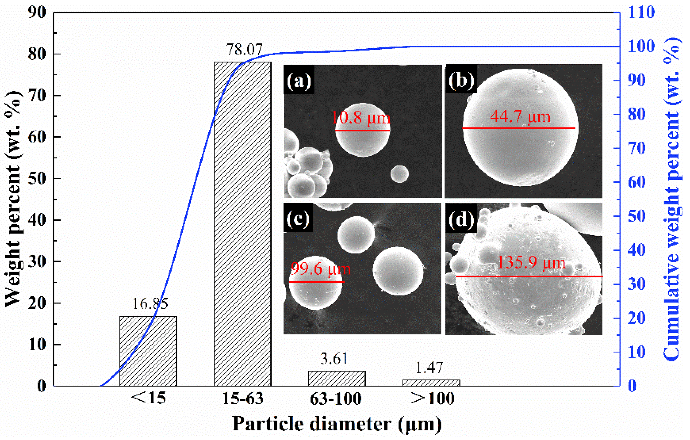
2.1. Powder and Coating

The Cu-Zr-Al-Ag-Co amorphous alloy powders were fabricated by a vacuum atomization device (HERMIGA100-20, Hailsham, England) supported by the Powder Metallurgy Research Institute, Central South University, Hunan, China. Different amounts of high-purity metals (Cu 99.999 wt.%, Zr 99.99 wt.%, Al 99.99 wt.%, Ag 99.99 wt.%, and Co 99.9999 wt.%) were atomized in a smelting chamber under an argon atmosphere. The powder fabrication parameters are listed in Table 1. The fabricated powders have a chemical formula of (Cu43Zr47Al7Ag3)99.5Co0.5 based on the nominal composition (at.%) of the elements (Cu 42.79, Zr 46.76, Al 6.96, Ag 2.99, and Co 0.50) measured by an inductively coupled plasma optical emission spectrometer (ICP-OES, ICAP 7200 Radial, Thermo Fisher Scientific, Waltham, MA, USA). The corresponding weight percent (wt.%) of the elements in the alloy is Cu 36.14, Zr 56.69, Al 2.50, Ag 4.28, and Co 0.39, respectively.
Coatings were fabricated on pure Cu substrate (22.0 × 28.0 × 8.0 mm3, Cu 99.95 wt.%, Fe < 0.001 wt.%, As < 0.01 wt.%, S < 0.04 wt.%) using the amorphous powders by a high-velocity air fuel (HVAF) spray system homemade by the National Key Laboratory for Remanufacturing of Beijing, China. The substrate samples were cleaned using an acetone–alcohol mixed solution to remove the grease and then sandblasted with alumina abrasive to obtain clean surfaces to enhance the bonding strength between the coating and substrate (the measured roughness of substrate surface was about 5 μm). The coating preparation parameters are given in Table 2. According to the different spray temperatures, three coatings were fabricated and labeled S1, S2, and S3.

2.2. Characterization of Powders and Coatings

The microstructure of the powders and coatings was characterized by a scanning electron microscope (SEM, Quanta-200, FEI, Eindhoven, Holland) and transmission electron microscopy (TEM, Tecnai G2 F30, FEI, Eindhoven, Holland) equipped with energy-dispersive X-ray spectroscopy (EDS, Oxford Instruments, Oxford, UK). The EDS measurements were operated in the secondary electron mode (15 kV) using an Oxford INCA system which has a 10 mm2 detector with 140 eV resolution. TEM samples were prepared by mechanical thinning and an ion milling process (TenuPol-5, Struers, Ballerup, Denmark). The powder foil TEM samples were prepared by the focused ion beam (FIB) lift-out technique. The porosity of the prepared coatings was measured for the SEM images using ImageJ software (V1.8.0). An X-ray diffraction analyzer (XRD, DX2700B, Shanghai precision instrument, Shanghai, China) with Cu Kα (λ = 1.54 Å) radiation at a scanning rate of 2°/min and scanning step of 0.02 was used to detect the phase constitutions of the powders and the surface-polished coatings. The volume fraction of the amorphous phase ( ω ) was calculated using the following equation [4]:
ω = A amor A amor + A cryst
where Aamor is the area of the amorphous hump at 2θ = 32.3°–44.6° and Acryst are the areas of all the crystalline phase peaks. The areas were calculated via the fitting curves of the XRD peaks. The thermal properties were examined by a differential thermal scanning analyzer (DSC, METTLER TGA/DSC 1600, Mettler toledo, Zurich, Switzerland).

2.3. Microhardness and Wear Tests

The microhardness of coatings was measured using an HXD-1000 microhardness tester (Shanghai taiming optical instrument, Shanghai, China) with a load of 100 g holding for 15 s. For the substrate and each coating, 20 points were measured, and the average data were reported. The bonding strength tests were conducted according to ASTM C633-79 standard using E7 epoxy adhesive (provided by Shanghai Research Institute of Synthetic Resins, China). Then, the samples were mounted in a tensile test machine (MTS-SANS, MTS, MI, USA) and stretched at a constant rate of 0.5 mm/min. The obtained strength was the mean value of five samples. Dry sliding wear tests of the coatings and substrate were conducted on a ball-on-plate Bruker CETR UMT-3 (Bruker, Billerica, America) wear testing machine under the linear reciprocating sliding mode at room temperature in air (Figure 1). A GCr15 grinding ball (840 HV) with a diameter of 4.0 mm was employed as the counterpart. The coating samples were 22.0 × 28.0 × 8.0 mm3 (Figure 1b). The tests lasted for 30 min at 40 mm/s under 10 N load. Before the wear test, the samples were wet ground with 2400 SiC paper and polished to a mirror finish (0.5 μm roughness). Three samples were tested to ensure data consistency. The wear volume loss was measured using a 3D topography scanner (OLS-4000, Olympus, Tokyo, Japan). The morphology of wear scars on the coatings was characterized by the Quanta-200 (FEI, Eindhoven, Holland) SEM equipped with EDS to detect the chemical compositions of the scars.

3. Results and Discussion

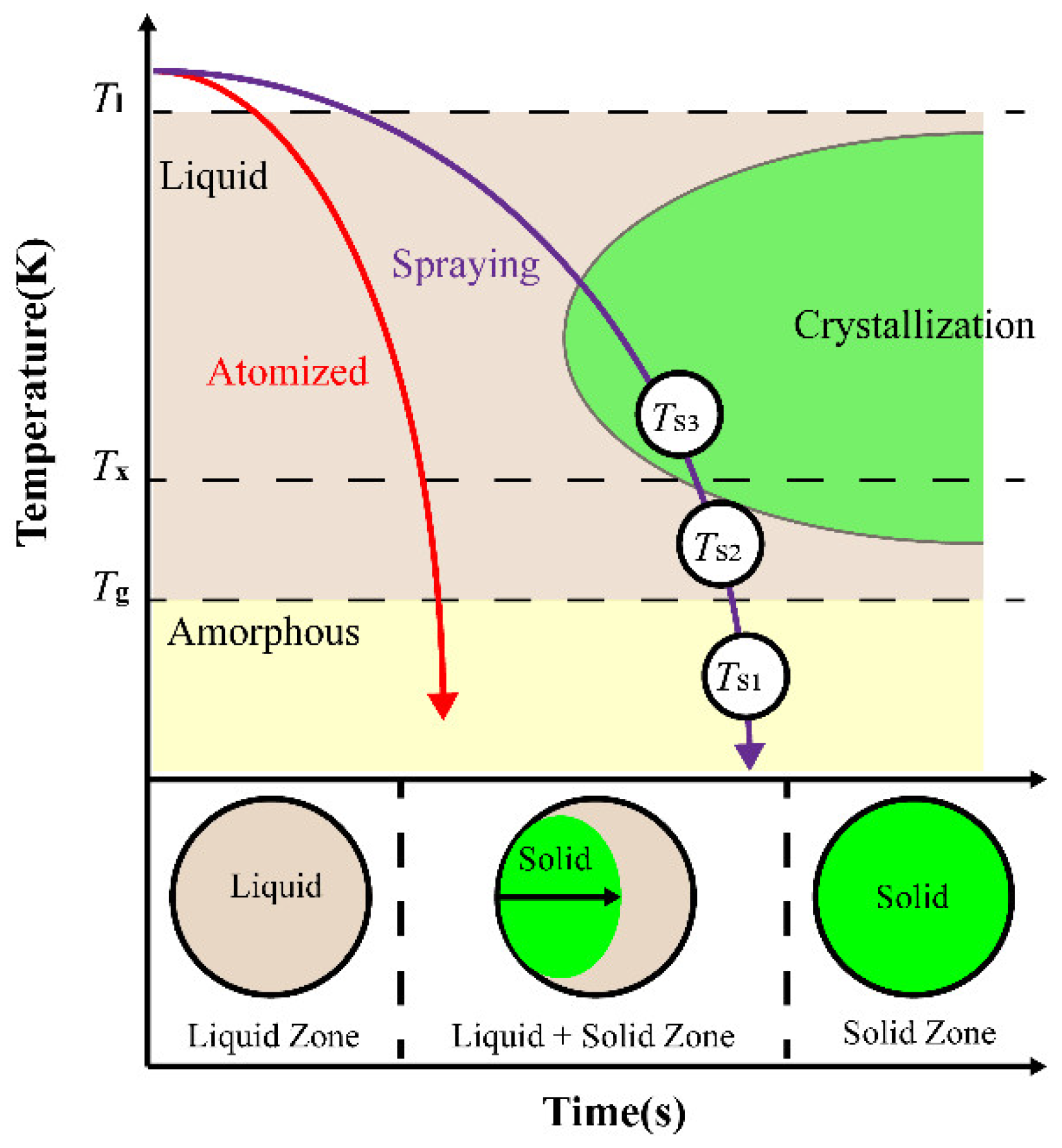
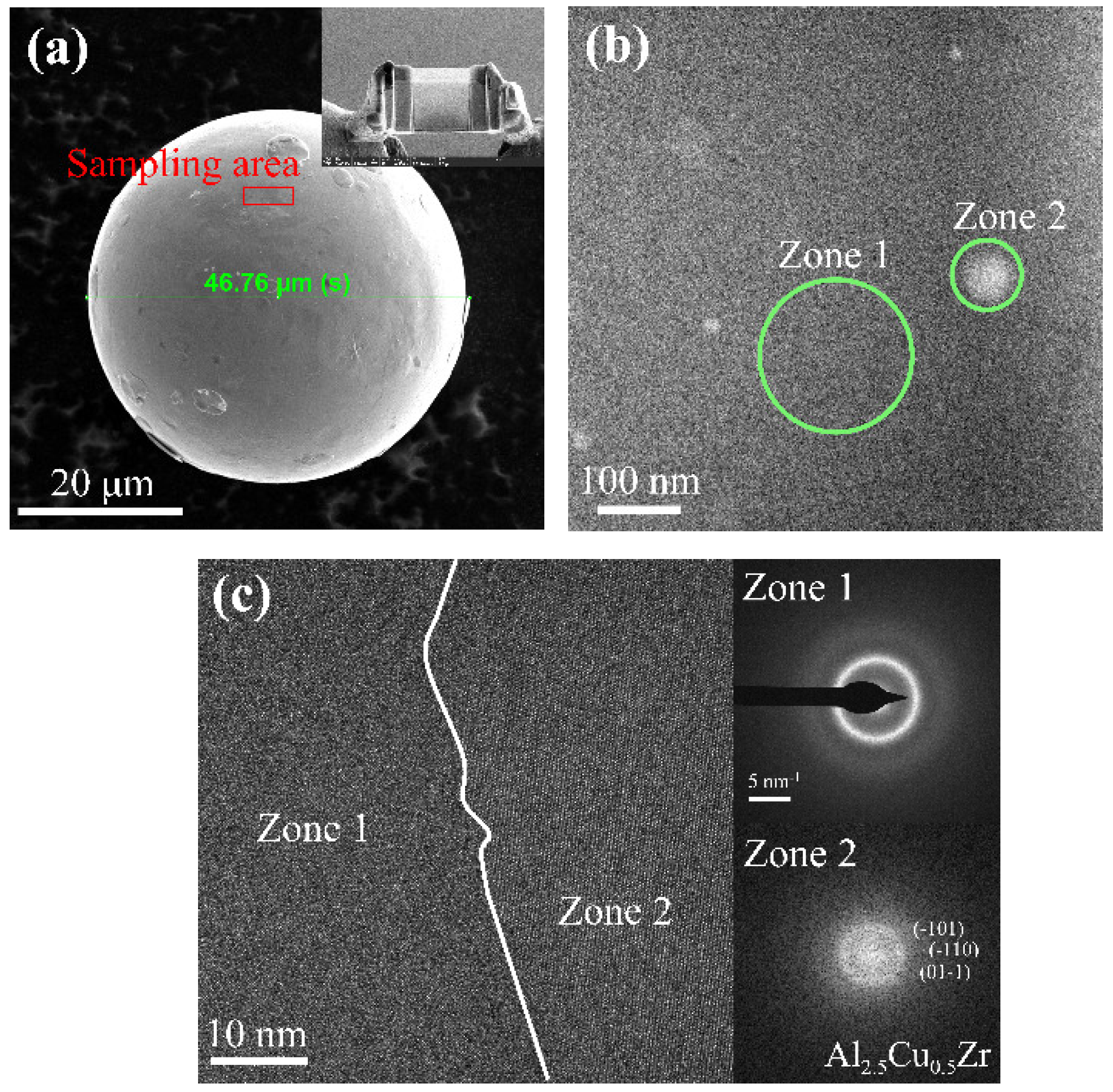
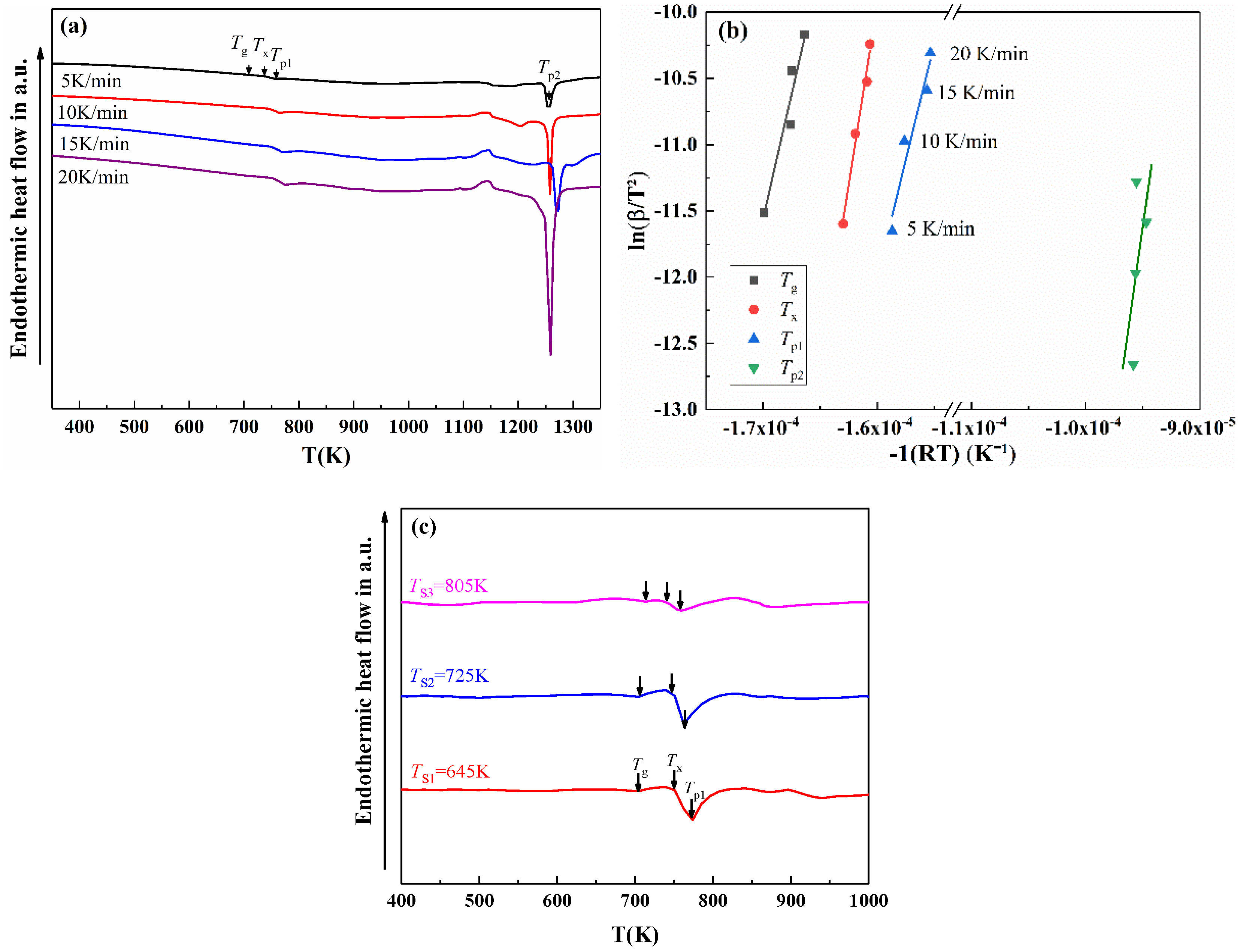
3.1. Phase Formation and Thermal Properties

The vacuum atomization process lasts a short time, fabricating the amorphous powders by rapidly decreasing the temperature below Tg. Such a process can be demonstrated in the schematic time–temperature transformation (TTT) curve in Figure 2. In theory, no crystallization occurs because nucleation of the crystalline phase is suppressed during the rapid quenching process [26]. This TTT curve in red in Figure 2 is valid since the as-atomized powders fabricated in this study have a relatively high ratio of amorphous phase (98.6 wt.%, according to the XRD results). For the HVAF spray, the melting and solidification of the feedstock materials are sequential. The local composition inhomogeneity will lead to a compositional fluctuation in particles, increasing the phase transformation driving force and promoting nucleation. Therefore, crystalline phases will precipitate. Moreover, oxidation happens when the powders are sprayed from the nozzle to the substrate due to the high temperature and large surface area of the spherical powders. Accordingly, the theoretical time–temperature transformation (TTT) curve for the HVAF spray process follows the purple curve in Figure 2. Along this TTT curve, three temperatures (TS1, TS2, and TS3) of spraying powders were selected according to the values of Tg and Tx of the powder and TS1 < Tg, Tg < TS2 < Tx, and Tx < TS3. Three coatings (S1, S2, and S3, corresponding to the three temperatures) are fabricated to evaluate the influences of temperatures on the microstructure and wear performance of the coatings.
In Figure 3, the fabricated (Cu43Zr47Al7Ag3)99.5Co0.5 amorphous powders have a wide range of particle sizes but 98 wt.% of them have a diameter smaller than 100 μm. Notably, the powders of 15–63 μm account for 78 wt.% of total powders. The insets of Figure 3 show the morphology of the powders at different particle sizes. The smaller powders generally have a smoother surface, and the powders in bigger sizes always have a few small satellite spheres. Figure 4 shows the TEM results of the amorphous powders with a diameter of 46.76 μm (Figure 4a). The chemical composition (at.%) of powders analyzed using EDS are Cu 42.72, Zr 46.88, Al 6.93, Ag 3.07, and Co 0.49. The results are consistent with the nominal chemical compositions of the (Cu43Zr47Al7Ag3)99.5Co0.5 alloy. The FIB slice of the powder in Figure 4b shows the even and compact structure. Noting that, in addition to the gray substrate (Zone 1), a few white particles (Zone 2) are also present in Figure 4b. Figure 4c shows the HRTEM images of Zone 1 and Zone 2. The diffraction pattern of Zone 1 shows a single amorphous halo, indicating the glassy structure. The fast Fourier transform (FFT) pattern of Zone 2 shows crystallized patterns belonging to the Al2.5Cu0.5Zr phase. The above results show that the 15–63 μm diameter powders with a smooth surface without satellite spheres are suitable for HVAF spray [1,6,26].
The XRD patterns of the powder (Figure 5a) reveal a typical broad diffraction hump between 35° and 45°, suggesting the amorphous characteristics. In addition to the hump, three peaks belonging to the new-formed phases (Al2.5Cu0.5Zr, AlZr3, and ZrO2) are detected for all three coatings. The Al2.5Cu0.5Zr and AlZr3 phases emerge due to the crystallization of the powder, and the ZrO2 phases come from oxidation. Figure 5b shows the increase in the weight percent (wt.%) of the three crystalline phases in S1, S2, S3 coatings. The Al2.5Cu0.5Zr phase takes over 1.4 wt.% of the powder, meaning that the amorphous phase dominates. The decreasing amount of amorphous phase of the coatings with increasing spray temperature indicates that the amorphous powders underwent a supercooled liquid region during coating deposition (see Figure 2), which induces structural relaxation conducive to crystallization [37]. Notably, the structural relaxation accumulates as the temperature of deposit layers increases, causing significant crystallization. In terms of the ZrO2 phase, the increase in its amount with spray temperatures is related to the strong reactivity and chemical affinity of Zr to oxygen.
Figure 6a shows the DSC traces of the (Cu43Zr47Al7Ag3)99.5Co0.5 amorphous alloy powders at different heating rates. The values of the glass transition temperature (Tg), onset crystallization temperature (Tx), and peak crystallization temperatures (Tp1 and Tp2) are given in Table 3. ΔTx (= TxTg) represents the supercooled liquid region [38,39]. The relatively bigger ΔTx of the (Cu43Zr47Al7Ag3)99.5Co0.5 powders at various heating rates in Table 3 indicates good thermal stability of the amorphous alloy. Moreover, the apparent activation energy (Figure 6b) of the powder is calculated based on the Kissinger’s method [40]:
ln ( B T 2 ) = E R T + C
where B is the heating rate (K/min), T is the crystallization peak temperature (K), E is the apparent activation energy (kJ/mol), R is the gas constant (8.314 J/(mol·K)), and C is a constant. The bigger energy values (Table 3) indicate that crystalline phases are more difficult to precipitate, verifying that the amorphous powder has better thermal stability. Figure 6c shows DSC traces of the three coatings at the heating rate of 20 K/min. With increasing temperature, Tg increases and Tx decreases, leading to a reduced ΔTx, indicating the degradation of thermal stability of the three coatings. Moreover, the gradually reduced Tp1 indicates that the crystalline phase is more likely to precipitate, consistent with the XRD results.

3.2. Characteristics of HVAF Sprayed Coatings

Figure 7 shows the surface and cross-section SEM images and EDS line scans of the amorphous alloy coatings. For the S1 coating fabricated at TS1 = 645 K, its surface is characterized by unmelted particles (Figure 7a). These particles impacted the substrate at high speed and were deposited on the substrate without undergoing phase transition and apparent plastic deformation, resulting in a weak mechanical bonding among particles. On the other hand, the spherical particles flattened and shattered into small parts due to the intensive impact. These unmelted particles develop a thick layer (about 600 μm) with large pores (7.24% porosity) and long cracks in the coating and at the coating/substrate interface (Figure 7b). The formation of defects (pores and cracks) can be attributed to the deficiency of appropriate plastic deformations. Although the coating is thick, the defects will cause the coating performance to deteriorate in practical usage.
Figure 7d shows partially melted particles on the S2 coating. These particles integrate metallurgically, leading to a better bonding state between coating and substrate (Figure 7e). Notably, the defects (1.65% porosity) are almost absent inside the coating, indicating that such a coating is promising in enhancing the performance of the substrate. Moreover, oxidation occurs with increasing heat input, which will degrade the glassy structure of the coating. By comparison, S3 coating exhibits fully melted particles and metallurgical bonding type, as shown in Figure 7g,h. Oxidation occurs readily at such a temperature (see the EDS elemental compositions at the dark spots in Figure 7h) when the heated particles fly in the air from the spray gun to the substrate. Meanwhile, the oxides congregate, contributing to oxidation voids in the S3 coating. Previous studies [41,42,43] reported that the melting states of spray particles affected the amorphous fractions of the coatings, i.e., a coating with a small amount of glassy structure develops if the spray particles are fully melted. In this study, with increasing spray temperature, the number of crystals increases (Figure 5b), consistent with the results reported by Kim et al. [42]. Importantly, compared with S3 coating, S2 coating exhibits a metallurgical bonding and relatively small crystalline amount, suggesting that TS2 is better than TS3 from the microstructure point of view.
The EDS elemental line scans from the coating to the substrate are similar, as shown in Figure 7c,f,i. There is no significant change in the content of each element in the coatings. Zr and Al decrease greatly from the coating to the substrate, whereas Cu increases significantly, matching well with the elemental compositions of the spraying powder and the Cu substrate. Such dramatic changes of Cu, Zr, and Al, especially for S1 and S2 coatings at the interface, indicate that no composition dilution occurs between coating and substrate during the spray. However, for the S3 coating, chemical composition dilution may occur at the interface because of heat accumulation during the spray. Noting that, along the red lines on the three coatings, Zr and O are abundant at some locations where Cu and Al are lower in content, attributed to the oxidation of spray particles.
The bonding types are characterized by TEM in the three coatings in Figure 8. There is a 2 nm thick crystalline layer at the particle boundary of the S1 coating in Figure 8a. The layer is formed by the ZrO2 phase based on the EDS mapping results. The oxides indicate the occurrence of oxidation on the surface of the spray powders. Moreover, the two particles in Figure 8a mechanically bond since the particles are squeezed together by the intensive impact exerted by subsequent particles. By comparison, Figure 8b and c show the typical metallurgical bonding characterized by regions of fusion (the green arrows) and more homogeneous fusion regions in the S2 coating. For the S2 coating, particle-like ZrO2 phases precipitate along the boundary, according to the EDS result of region 1 (Figure 8b.1). By comparison, the EDS result of region 2, inside the particle, shows slighter oxidation. For the S3 coating, larger particle-like ZrO2 phases precipitate along the boundary (region 4), and bigger Al2.5Cu0.5Zr phases precipitate (region 3) in the powders. Although both S2 and S3 coatings exhibit metallurgical bonding, the S3 coating has bigger crystalline phases in size and amount. These grown-up crystals in the S3 coating indicate the occurrence of recrystallization and apparent oxidation, bringing about more structural defects (cracks and oxidation pores in Figure 7h).

3.3. Wear Resistance Properties of HVAF Coatings

Figure 9 shows the bonding strength and microhardness of three coatings. The bonding strength of the coatings reaches 40–60 MPa, which approximates the bonding strength of coatings fabricated by HVOF and arc plasma spray (APS) techniques [44,45]. The bonding strength is strongly associated with the bonding types and the microstructure of the coatings. The S2 coating has metallurgical bonding and the lowest defects, possessing the most considerable bonding strength of 59.3 MPa. The microhardness reaches 475 HV0.1 for S1 coating, 554 HV0.1 for S2 coating, and 528 HV0.1 for S3 coating. All the values are bigger than the hardness of the substrate (93 HV0.1). The microhardness is associated with the crystalline phases formed during spray and the porosity of the coating. As a result, the microhardness of the S2 coating is the highest due to its lowest porosity (1.65%). As a comparison, the bonding strength and microhardness of a high-aluminum bronze coating (S0) fabricated by Li et al. [46] are also plotted in Figure 9 to show that the coatings in this work have good mechanical properties.
The wear tests were carried out on the polished surface of the coatings to exclude the influence of surface roughness on the wear properties. Figure 10 shows the measured coefficient of friction (COF) concerning the sliding duration of the three coatings and the wear volume loss taking the substrate as a comparison. In Figure 10a, the COFs of the coatings are all smaller than that of the substrate. The COFs of S1 and S2 coatings are relatively steady, especially at the sliding end due to the relatively homogeneous microstructure. The COF of the S3 coating is higher than the S1 and S2 coatings. Additionally, a large fluctuation in COF emerges on the S3 coating, attributed to the difference in hardness between the amorphous structure and grown-up crystalline phases. Previous studies [4,15,47] have revealed a direct correlation between wear resistance and hardness. The wear rate (Rw) of the material can be calculated by the following formula [4,47]:
R w = k N H
where k is the COF value (the average value extracted from the stable period in Figure 10a), N is the load of 10 N, and H is the hardness of the materials (HV0.1). Based on Equation (3), Rw of the substrate and S1, S2, and S3 coatings are obtained and noted in Figure 10a. The coatings have a lower wear rate than the substrate, and the S2 coating has the smallest value although it has a bigger COF than the S1 coating. The results of wear rate show that the S2 coating possesses the best wear resistance properties. Figure 10b shows the wear volume loss (mm3). Agreeing with the wear resistance, the coatings all have a smaller wear volume than the substrate, and the average wear volume (0.033 mm3) for the S2 coating is only one-tenth of that for substrate (0.326 mm3).
Figure 11 shows SEM images of wear tracks of the coatings and the corresponding EDS results. Figure 11a,d,g present the wear morphology images as the spraying temperature increases from 645 to 805 K. It can be found that the wear scar width of the amorphous coatings is about 1492 μm (S1), 1243 μm (S2), and 1567 μm (S3), respectively. The S2 coating has the narrowest wear scar (Figure 11d), indicating a good resistance to wear. The worn surfaces of the coatings are also characterized by large areas of wear grooves and tribofilm. The enlarged worn surfaces in Figure 11b,c,e,f,h,i exhibit the detailed wear damage including adhesive smearing, wear debris, and micro-ploughing. For the S1 and S3 coatings, delamination of materials and cracks can also be observed while being absent on the S2 coatings’ worn surface. Due to the existence of delamination, cracks, and debris, the loss of material occurs on all three coatings (Figure 10b). However, compared with S1 and S3 coatings, the amount of wear debris and delamination is much less for the S2 coating, possibly due to its lowest porosity. The EDS analysis of the tribofilm and wear debris at points A–E show that the tribofilm has a smaller amount of O and Fe compared with the wear debris, suggesting that further oxidation happens on the spalling debris whereas the tribofilm formed by the adhesive debris does not experience such oxidation during cyclic friction [48]. Importantly, more extensive oxidation occurs on the S2 and S3 coatings compared with the S1 coating. Moreover, the Fe element which comes from the GCr15 ball confirms the adhesive transfer of materials between the coating and the ball. However, the Fe content is smaller than 1.0 wt.%, suggesting the insignificant wear damage on the ball.
With the aim to elucidate the microstructural differences of three coatings on affecting the wear mechanism, Figure 12 illustrates the schematic diagram of the three coatings before and after wear tests. The S2 coating fabricated at the temperature between Tg and Tx possesses a compact structure characterized by partially melted particles, metallurgical bonding, and minor defects (Figure 12b) compared with the S1 coating (Figure 12a) and S3 coating (Figure 12c). As a result, the bonding strength and microhardness are the biggest, endowing the S2 coating with relatively good mechanical and wear properties. It has been reported that the wear resistance of sprayed coatings also depends on the fraction of the crystalline to the amorphous phase. Greer et al. [49] reported that the optimum crystalline fraction in the coating structure is 30–40 wt.% for obtaining wear-resistant metallic glasses. The S2 coating contains 32.5 wt.% crystal phase and exhibits minimum wear rate, consistent with Greer et al.
After wear tests, the worn surface of S1 coating is characterized by a bigger area of tribofilm, abrasive-induced delamination of material, and adhesive smashing of debris, indicating that the wear mechanism is the coexistence of abrasive and adhesive wear. For S3 coating, the abrasive-induced delamination is more significant because more oxides develop. Thus, S3 exhibits easier delamination of coating materials. For the S2 coating, the loss of coating material is slightly due to its high mechanical bonding, insignificant defects, and high adhesion. However, the hard oxides play a role in the abrasive wear of the coating, leading to the dominating abrasive mechanism. Moreover, the adhesive smearing and delamination are slight, suggesting adhesive wear is not the main mechanism. Overall, abrasive and adhesive wear happens to all three coatings, but abrasive wear dominates on the S2 coating wear, and the wear mechanism on S1 and S3 coating is mainly adhesive wear.

4. Conclusions

The (Cu43Zr47Al7Ag3)99.5Co0.5 amorphous coatings were fabricated by HVAF spray technology at different temperatures close to the glass transition temperature (Tg) and onset crystallization temperature (Tx) of the alloy. The microstructure and wear resistance properties were investigated to evaluate the influences of the temperatures.
(1) The (Cu43Zr47Al7Ag3)99.5Co0.5 amorphous alloy powders that have a diameter of 15–63 μm primarily consist of an amorphous phase (the content is 98.6 wt.%) and a crystalline phase (Al2.5Cu0.5Zr). The powder also has good thermal stability.
(2) The spray temperatures greatly influence the microstructure and crystalline phases of coatings. As temperature increases, more spray particles are melted, and the bonding types among particles evolve from mechanical bonding to metallurgical bonding. Moreover, crystalline phases precipitate easily at higher temperatures. Two new phases (AlZr3 and ZrO2) emerge, and their contents increase with temperature.
(3) When the spray temperature is between Tg and Tx, the fabricated coating has the highest amorphous content (~67.5 wt.%), lowest porosity (1.65%), fewer defects, and metallurgical bonding, which contribute to the highest bonding strength (59.3 MPa), microhardness (554 HV0.1), the smallest wear volume loss (0.033 mm3), and the lowest wear rate (4.6 × 10⁻⁵ mm3/Nm). For this coating, the wear mechanism is mainly abrasive wear in addition to slight adhesive wear.
(4) Under appropriate spray conditions, the HVAF sprayed Cu-Zr-Al-Ag-Co amorphous coating has good mechanical and wear resistance properties simultaneously. Such coatings are promising to be used in various applications such as aerospace, automobile, and biomedicine industries. Future work focuses on multi-functions (e.g., wear resistance, corrosion resistance, super-hydrophobic, etc.) of the HVAF sprayed amorphous coatings attained by deliberately adjusting alloying components and spray parameters.

Author Contributions

Conceptualization, S.W. and X.W.; methodology, S.W.; software, Y.Z.; validation, W.M., S.W. and G.H.; formal analysis, G.H.; investigation, Z.R. and C.D.; resources, X.W.; data curation, S.W.; writing—original draft preparation, S.W.; writing—review and editing, W.M.; visualization, Y.Z. and C.D.; supervision, W.M.; project administration, W.M.; funding acquisition, W.M. All authors have read and agreed to the published version of the manuscript.

Funding

This work was supported by the National Key R&D Program of China (Grant No. 2018YFB1105800); the Young Elite Scientists Sponsorship Program by CAST (Grant No. 2017QNRC001); the National Natural Science Foundation of China (Grant Nos. 11772287, 11802260).

Institutional Review Board Statement

Not applicable.

Informed Consent Statement

Not applicable.

Data Availability Statement

Not applicable.

Acknowledgments

The authors sincerely thank the Metallurgy Research Institute of Central South University for powder sample preparation.

Conflicts of Interest

The authors declare no conflict of interest.

References

  1. Mahade, S.; Aranke, O.; Björklund, S.; Dizdar, S.; Awe, S.; Mušálek, R.; Lukáč, F.; Joshi, S. Influence of processing conditions on the microstructure and sliding wear of a promising Fe-based coating deposited by HVAF. Surf. Coat. Technol. 2021, 409, 126953. [Google Scholar] [CrossRef]
  2. Liao, Y.C.; Song, S.M.; Li, T.H.; Chiang, Y.L.; Tsai, P.H.; Nguyen, V.T.; Li, S.Y.; Jang, J.S.C.; Huang, J.C. Significant TRIP-effect improvement by manipulating ZrCu-B2 distribution in ZrCuAlCo-based bulk metallic glass composites via inoculating Ta particles. J. Alloys Compd. 2019, 774, 547–555. [Google Scholar] [CrossRef]
  3. Khan, M.M.; Nemati, A.; Rahman, Z.U.; Shah, U.H.; Asgar, H.; Haider, W. Recent advancements in bulk metallic glasses and their applications: A review. Crit. Rev. Solid State Mater. Sci. 2018, 43, 233–268. [Google Scholar] [CrossRef]
  4. Si, C.; Duan, B.; Zhang, Q.; Cai, J.; Wu, W. Microstructure, corrosion-resistance, and wear-resistance properties of subsonic flame sprayed amorphous Fe-Mo-Cr-Co coating with extremely high amorphous rate. J. Mater. Res. Technol. 2020, 9, 3292–3303. [Google Scholar] [CrossRef]
  5. Sıkan, F.; Atabay, S.E.; Motallebzadeh, A.; Özerinç, S.; Kalay, I.; Kalay, Y.E. Effect of Sm on thermal and mechanical properties of Cu-Zr-Al bulk metallic glasses. Mater. Sci. Eng. A 2019, 743, 168–174. [Google Scholar] [CrossRef]
  6. Huang, B.; Zhang, C.; Zhang, G.; Liao, H. Wear and corrosion resistant performance of thermal-sprayed Fe-based amorphous coatings: A review. Surf. Coat. Technol. 2019, 377, 124896. [Google Scholar] [CrossRef]
  7. Filipecka, K.; Pawlik, P.; Filipecki, J. The effect of annealing on magnetic properties, phase structure and evolution of free volumes in Pr-Fe-B-W metallic glasses. J. Alloys Compd. 2017, 694, 228–234. [Google Scholar] [CrossRef]
  8. Monfared, A.; Vali, H.; Faghihi, S. Biocorrosion and biocompatibility of Zr-Cu-Fe-Al bulk metallic glasses. Surf. Interface Anal. 2013, 45, 1714–1720. [Google Scholar] [CrossRef]
  9. Sohrabi, N.; Panikar, R.S.; Jhabvala, J.; Buch, A.R.; Mischler, S.; Logé, R.E. Laser coating of a Zr-based metallic glass on an aluminum substrate. Surf. Coat. Technol. 2020, 400, 126223. [Google Scholar] [CrossRef]
  10. Ye, X.; Bae, H.; Shin, Y.C.; Stanciu, L.A. In situ synthesis and characterization of Zr-based amorphous composite by laser direct deposition. Metall. Mater. Trans. A 2015, 46, 4316–4325. [Google Scholar] [CrossRef]
  11. Cai, B.; Yang, L. Enhanced corrosion and wear resistances of Zr-based alloy induced by amorphous/nanocrystalline coating. J. Wuhan Univ. Technol. Mater. Sci. Ed. 2019, 34, 791–797. [Google Scholar] [CrossRef]
  12. Liu, Y.; Padmanabhan, J.; Cheung, B.; Liu, J.; Chen, Z.; Scanley, B.E.; Wesolowski, D.; Pressley, M.; Broadbridge, C.C.; Altman, S.; et al. Combinatorial development of antibacterial Zr-Cu-Al-Ag thin film metallic glasses. Sci. Rep. 2016, 6, 26950. [Google Scholar] [CrossRef] [PubMed] [Green Version]
  13. Liang, D.; Ma, J.; Cai, Y.; Liu, X.; Xie, S.; Wei, X.; Xu, G.; Shen, J. Characterization and elevated-temperature tribological performance of AC–HVAF-sprayed Fe-based amorphous coating. Surf. Coat. Technol. 2020, 387, 125535. [Google Scholar] [CrossRef]
  14. Xie, L.; Xiong, X.; Zeng, Y.; Wang, Y. The wear properties and mechanism of detonation sprayed iron-based amorphous coating. Surf. Coat. Technol. 2019, 366, 146–155. [Google Scholar] [CrossRef]
  15. Yugeswaran, S.; Kobayashi, A.; Suresh, K.; Rao, K.P.; Subramanian, B. Wear behavior of gas tunnel type plasma sprayed Zr-based metallic glass composite coatings. Appl. Surf. Sci. 2012, 258, 8460–8468. [Google Scholar] [CrossRef]
  16. Wang, Q.; Han, P.; Yin, S.; Niu, W.-J.; Zhai, L.; Li, X.; Mao, X.; Han, Y. Current research status on cold sprayed amorphous alloy coatings: A review. Coatings 2021, 11, 206. [Google Scholar] [CrossRef]
  17. Iqbal, A.; Siddique, S.; Maqsood, M.; Rehman, M.A.U.; Yasir, M. Comparative analysis on the structure and properties of Iron-based amorphous coating sprayed with the thermal spraying techniques. Coatings 2020, 10, 1006. [Google Scholar] [CrossRef]
  18. Wang, Y.; Jiang, S.L.; Zheng, Y.G.; Ke, W.; Sun, W.H.; Chang, X.C.; Hou, W.L.; Wang, J.Q. Effect of processing parameters on the microstructures and corrosion behaviour of high-velocity oxy-fuel (HVOF) sprayed Fe-based amorphous metallic coatings. Mater. Corros. 2013, 64, 801–810. [Google Scholar] [CrossRef]
  19. Wu, Y.; Luo, Q.; Jiao, J.; Wei, X.; Shen, J. Investigating the wear behavior of Fe-based amorphous coatings under nanoscratch tests. Metals 2017, 7, 118. [Google Scholar] [CrossRef] [Green Version]
  20. Ma, H.R.; Li, J.W.; Jiao, J.; Chang, C.T.; Wang, G.; Shen, J.; Wang, X.M.; Li, R.W. Wear resistance of Fe-based amorphous coatings prepared by AC-HVAF and HVOF. Mater. Sci. Technol. 2017, 33, 65–71. [Google Scholar] [CrossRef]
  21. Guo, R.Q.; Zhang, C.; Chen, Q.; Yang, Y.; Li, N.; Liu, L. Study of structure and corrosion resistance of Fe-based amorphous coatings prepared by HVAF and HVOF. Corros. Sci. 2011, 53, 2351–2356. [Google Scholar] [CrossRef]
  22. Huang, F.; Kang, J.J.; Yue, W.; Fu, Z.Q.; Zhu, L.N.; She, D.S.; Liang, J.; Wang, C.B. Corrosion behavior of FeCrMoCBY amorphous coating fabricated by high-velocity air fuel Spraying. J. Therm. Spray Technol. 2019, 28, 842–850. [Google Scholar] [CrossRef]
  23. Gao, M.; Lu, W.; Yang, B.; Zhang, S.; Wang, J. High corrosion and wear resistance of Al-based amorphous metallic coating synthesized by HVAF spraying. J. Alloys Compd. 2018, 735, 1363–1373. [Google Scholar] [CrossRef]
  24. Si, C.; Wu, W. Excellent corrosion resistant amorphous coating prepared by gas atomization followed by AC-HVAF spray technology. Mater. Res. Express 2019, 6, 055202. [Google Scholar] [CrossRef]
  25. Guo, H.; Zhang, S.; Sun, W.; Wang, J. Differences in dry sliding wear behavior between HVAF-sprayed amorphous steel and crystalline stainless steel coatings. J. Mater. Sci. Technol. 2019, 35, 865–874. [Google Scholar] [CrossRef]
  26. Guo, W.; Wu, Y.; Zhang, J.; Hong, S.; Li, G.; Ying, G.; Guo, J.; Qin, Y. Fabrication and characterization of thermal-sprayed Fe-based amorphous/nanocrystalline composite coatings: An overview. J. Therm. Spray Technol. 2014, 23, 1157–1180. [Google Scholar] [CrossRef]
  27. Zhang, C.; Guo, R.Q.; Yang, Y.; Wu, Y.; Liu, L. Influence of the size of spraying powders on the microstructure and corrosion resistance of Fe-based amorphous coating. Electrochim. Acta 2011, 56, 6380–6388. [Google Scholar] [CrossRef]
  28. Movahedi, B.; Enayati, M.H.; Wong, C.C. Structural and thermal behavior of Fe-Cr-Mo-P-B-C-Si amorphous and nanocrystalline HVOF coatings. J. Therm. Spray Technol. 2010, 19, 1093–1099. [Google Scholar] [CrossRef]
  29. Zhou, Z.; Wang, L.; Wang, F.C.; Zhang, H.F.; Liu, Y.B.; Xu, S.H. Formation and corrosion behavior of Fe-based amorphous metallic coatings by HVOF thermal spraying. Surf. Coat. Technol. 2009, 204, 563–570. [Google Scholar] [CrossRef]
  30. Zois, D.; Lekatou, A.; Vardavoulias, M. Preparation and characterization of highly amorphous HVOF stainless steel coatings. J. Alloys Compd. 2010, 504, S283–S287. [Google Scholar] [CrossRef]
  31. Wang, A.P.; Wang, Z.M.; Zhang, J.; Wang, J.Q. Deposition of HVAF-sprayed Ni-based amorphous metallic coatings. J. Alloys Compd. 2007, 440, 225–228. [Google Scholar] [CrossRef]
  32. Yuan, R.; Yu, Z.; Leng, H.; Chou, K. Thermodynamic evaluation and experimental verification of the glass forming ability of Cu-Zr-based alloys. J. Non-Cryst. Solids 2021, 564, 120835. [Google Scholar] [CrossRef]
  33. Xu, Y.; Jeurgens, L.P.H.; Bo, H.; Lin, L.; Zhu, S.; Huang, Y.; Liu, Y.; Qiao, J.; Wang, Z. On the competition between synchronous oxidation and preferential oxidation in Cu-Zr-Al metallic glasses. Corros. Sci. 2020, 177, 108996. [Google Scholar] [CrossRef]
  34. Inoue, A.; Takeuchi, A. Recent development and application products of bulk glassy alloys. Acta Mater. 2011, 59, 2243–2267. [Google Scholar] [CrossRef]
  35. Bouala, G.I.N.; Etiemble, A.; der Loughian, C.; Langlois, C.; Pierson, J.F.; Steyer, P. Silver influence on the antibacterial activity of multi-functional Zr-Cu based thin film metallic glasses. Surf. Coat. Technol. 2018, 343, 108–114. [Google Scholar] [CrossRef]
  36. Escher, B.; Kühn, U.; Eckert, J.; Rentenberger, C.; Pauly, S. Influence of Ag and Co additions on glass-forming ability, thermal and mechanical properties of Cu–Zr–Al bulk metallic glasses. Mater. Sci. Eng. A 2016, 673, 90–98. [Google Scholar] [CrossRef]
  37. Kang, Y.; Chen, Y.; Wen, Y.; Wu, B.; Song, M. Effects of structural relaxation and crystallization on the corrosion resistance of an Fe-based amorphous coating. J. Non-Cryst. Solids. 2020, 550, 120378. [Google Scholar] [CrossRef]
  38. Zhang, Y.; Zhou, M.; Zhao, X.Y.; Ma, L.Q. Co substituted Zr-Cu-Al-Ni metallic glasses with enhanced glass-forming ability and high plasticity. J. Non-Cryst. Solids 2017, 473, 120–124. [Google Scholar] [CrossRef]
  39. Gammer, C.; Escher, B.; Ebner, C.; Minor, A.M.; Karnthaler, H.P.; Eckert, J.; Pauly, S.; Rentenberger, C. Influence of the Ag concentration on the medium-range order in a CuZrAlAg bulk metallic glass. Sci. Rep. 2017, 7, 44903. [Google Scholar] [CrossRef] [Green Version]
  40. Zheng, H.; Lv, Y.; Sun, Q.; Hu, L.; Yang, X.; Yue, Y. Thermodynamic evidence for cluster ordering in Cu46Zr42Al7Y5 ribbons during glass transition. Sci. Bull. 2016, 61, 706–713. [Google Scholar] [CrossRef] [Green Version]
  41. List, A.; Gärtner, F.; Mori, T.; Schulze, M.; Assadi, H.; Kuroda, S.; Klassen, T. Cold spraying of amorphous Cu50Zr50 alloys. J. Therm. Spray Technol. 2015, 24, 108–118. [Google Scholar] [CrossRef]
  42. Kim, J.; Kang, K.; Yoon, S.; Kumar, S.; Na, H.; Lee, C. Oxidation and crystallization mechanisms in plasma-sprayed Cu-based bulk metallic glass coatings. Acta Mater. 2010, 58, 952–962. [Google Scholar] [CrossRef]
  43. Kim, J.; Kang, K.; Yoon, S.; Lee, C. Enhancement of metallic glass properties of Cu-based BMG coating by shroud plasma spraying. Surf. Coat. Technol. 2011, 205, 3020–3026. [Google Scholar] [CrossRef]
  44. Blink, J.; Farmer, J.; Choi, J.; Saw, C. Applications in the nuclear industry for thermal spray amorphous metal and ceramic coatings. Metall. Mater. Trans. A 2009, 40, 1344–1354. [Google Scholar] [CrossRef] [Green Version]
  45. Moreau, C.; Cielo, P.; Lamontagne, M.; Dallaire, S.; Krapez, J.C.; Vardelle, M. Temperature evolution of plasma-sprayed niobium particles impacting on a substrate. Surf. Coat. Technol. 1991, 46, 173–187. [Google Scholar] [CrossRef]
  46. Feng, L.; Li, D.; An, G.; Wang, G.; Li, W.; Chang, J. Effect of powder particle size on microstructure and properties of low pressure cold sprayed high aluminium bronze coating. Mater. Res. Express 2020, 7, 026524. [Google Scholar] [CrossRef]
  47. Zhang, H.; Xie, Y.; Huang, L.; Huang, S.; Zheng, X.; Chen, G. Effect of feedstock particle sizes on wear resistance of plasma sprayed Fe-based amorphous coatings. Surf. Coat. Technol. 2014, 258, 495–502. [Google Scholar] [CrossRef]
  48. Michalak, M.; Sokołowski, P.; Szala, M.; Walczak, M.; Łatka, L.; Toma, F.L.; Björklund, S. Wear behavior analysis of Al2O3 coatings manufactured by APS and HVOF spraying processes using powder and suspension feedstocks. Coatings 2021, 11, 879. [Google Scholar] [CrossRef]
  49. Greer, A.L.; Rutherford, K.L.; Hutchings, I.M. Wear resistance of amorphous alloys and related materials. Int. Mater. Rev. 2002, 47, 87–112. [Google Scholar] [CrossRef]
Figure 1. (a) Reciprocating ball-on-plate type wear tester, (b) schematic illustration of a GCr15 ball sliding on the coating.
Coatings 12 00458 g001
Figure 2. Schematic time–temperature transformation (TTT) curve for the (Cu43Zr47Al7Ag3)99.5Co0.5 amorphous powder and the temperatures (TS1, TS2, and TS3) selected for HVAF spray. (Note: TS1 < Tg, Tg < TS2 < Tx, and Tx < TS3.)
Coatings 12 00458 g002
Figure 3. Size distribution and SEM images of the gas-atomized amorphous powders. (a) 10.8 μm, (b) 44.7 μm, (c) 99.6 μm, (d) 135.9 μm.
Coatings 12 00458 g003
Figure 4. TEM analyses of (Cu43Zr47Al7Ag3)99.5Co0.5 amorphous powder. (a) A typical powder with the diameter of 46.76 μm, (b) the TEM bright-field image, (c) the HRTEM image obtained at the interface of Zone 1 and Zone 2. The insert images: the diffraction pattern of Zone 1 and the FTT of Zone 2.
Coatings 12 00458 g004
Figure 5. (a) XRD results and (b) the weight percent of the phases for the (Cu43Zr47Al7Ag3)99.5Co0.5 amorphous powder and coatings.
Coatings 12 00458 g005
Figure 6. (a) DSC traces of (Cu43Zr47Al7Ag3)99.5Co0.5 amorphous powder, (b) the apparent activation energy of the powder, and (c) DSC traces at the heating rate 20 K/min of the coatings.
Coatings 12 00458 g006
Figure 7. The surface and cross-section SEM images of (a,b) S1, (d,e) S2, and (g,h) S3 HVAF sprayed coatings. (c,f,i) are the corresponding EDS line scan results.
Coatings 12 00458 g007
Figure 8. TEM and EDS results of the boundaries between two spraying particles. (a) S1, (b) S2, (c) S3. (a.1) EDX mapping of S1. (b.1,b.2) EDS results of S2. (c.1,c.2) SAED patterns of S3.
Coatings 12 00458 g008
Figure 9. Bonding strength and microhardness of the coatings.
Coatings 12 00458 g009
Figure 10. (a) Relationship between the COFs and sliding duration and (b) the wear volume loss and wear rates of three coatings taking the substrate as a comparison.
Coatings 12 00458 g010
Figure 11. SEM images of wear tracks and the EDS elemental analysis of the wear surfaces of the coatings, (ac) S1, (df) S2, and (gi) S3.
Coatings 12 00458 g011
Figure 12. Schematic diagram of wear mechanisms of the three coatings. (a,d) S1; (b,e) S2; (c,f) S3.
Coatings 12 00458 g012
Table 1. Vacuum atomization parameters for fabricating Cu-Zr-Al-Ag-Co amorphous alloy powders.
Atomization
Gas
Gas Pressure
(MPa)
Gas Velocity
(mm/s)
Superheat Temperature
(°C)
Flow Diameter
(mm)
Melt Velocity
(kg/min)
N23.51452155–101.4
Table 2. The amorphous coating preparation parameters.
No.Spray Temperature
(K)
Ratio of
Air/Propane Pressure
N2
(L/min)
Spray Distance
(mm)
Powder Feeding Rate (g/s)Scan Rate
(mm/s)
Coating Thickness (μm)
S164590/80351600.6400560.6 ± 23
S272590/86594.3 ± 16
S380590/90602.6 ± 15
Table 3. The characteristic temperatures obtained by DSC traces for (Cu43Zr47Al7Ag3)99.5Co0.5 amorphous powders and the corresponding activation energies.
Heating RatesTg/KTx/KTp1/KTp2/KΔTx/K
5 K707.9737.9757.91255.330.0
10 K717.8742.8763.11257.925.0
15 K718.1747.6772.81270.429.5
20 K723.0748.8774.21258.925.8
Activation energy, E
(kJ/mol)
377.7 ± 7.4537.9 ± 5.0350.7 ± 6.6619.5 ± 7.1\
Publisher’s Note: MDPI stays neutral with regard to jurisdictional claims in published maps and institutional affiliations.

