3.2. Electrochemical Characteristics
Figure 5 shows that the open circuit potential of steel substrate is −0.563 V (vs. SCE), and that of the thermal-spray zinc and inorganic zinc-rich coating are −1.078 V (vs. SCE) and −0.971 V (vs. SCE). The corrosion potentials of the two kinds of coatings are much lower than the open circuit potential of the substrate, which could provide cathodic protection for the substrate. The comparison of the two kinds of zinc coatings shows that the open circuit potential of inorganic zinc-rich coating is higher than that of the thermal-spray zinc coating. From the perspective of corrosion tendency, the thermal-spray zinc coating is more likely to corrode. Due to the addition of polymer materials, the conductivity of inorganic zinc-rich coating is poor; thus, corrosion does not occur so easily [
12,
13], and plays an anti-corrosion role under the function of providing cathodic protection. The data analysis of the open circuit potential provides a new idea for the formulation design of zinc coating. As for the role of cathode protection, it is necessary to coordinate the two important aspects of anode sacrifice and corrosion inhibition, so that the formula performance can be maximized.
As shown by the data for corrosion current in
Figure 6 and
Table 1, at the initial salt-spray stage, the surface of the thermal-spray zinc coating is corroded evenly and the potential of the electrode is negative (−1.242 V vs. SCE); moreover, the corrosion dissolution rate is fast, with a corrosion current density of 1.69 × 10
−3 A. After 1200 h of salt spray and the formation of corrosion products, the corrosion current decreases and the corrosion potential changes to −1.102 V (vs. SCE); however, the instability of the corrosion products causes the corrosion current data to be dispersed and to fluctuate within a certain range. Generally speaking, with the extension of salt-spray time, the corrosion potential of the thermal-spray zinc coating gradually moves forward, the dissolution rate of the zinc coating shows a downward trend, and the corrosion current gradually decreases. The possible reason is that after the zinc dissolves, new corrosion products are generated to cover the surface of the thermal-sprayed zinc, preventing further corrosion and dissolution of the zinc inside the coating. Finally, after 7500 h of salt spray, the corrosion potential increases to −0.824 V (vs. SCE) and the corrosion current decreases to 1.32 × 10
−4 A [
14].
The Tafel slope and corrosion current value data are modified and updated. The open circuit potential of thermal-spray zinc in the absence of salt spray is reduced after 500 h of accelerated salt-spray corrosion, which is caused by the coating construction process and self-curing characteristics of thermal-spray zinc. During the cooling process of zinc, the local surface of the coating is uneven, resulting in high porosity of the coating. The salt-spray environment accelerates corrosion; consequently, penetrative corrosive media such as chloride ions can pass through the pores quickly and penetrate into the interior of the thermal-spray zinc coating, and even the surface of the substrate, accelerating corrosion and increasing the damage to the paint film. Since pure zinc forms a coating with high porosity, which accelerates the corrosion rate in this time period, the corrosion potential of the coating is lower than that of the non-corroded coating in the early stage of the accelerated salt-spray test. After a period of accelerated corrosion, due to the formation of new corrosion products chelated on the coating surface, the corrosion products inhibit the diffusion of chloride ions, thus playing a blocking role and reducing the corrosion rate of zinc, as well as gradually increasing the corrosion potential.
The Nyquist curves of AC impedance in
Figure 7 and
Figure 8 show that the samples basically have the same trend after being salt sprayed for different durations. The Nyquist charts are composed of a high-frequency single-capacity reactance arc and a low-frequency Warburg impedance diffusion arc. The high-frequency impedance spectroscopy reflects the coating information, while the low-frequency impedance spectroscopy reflects the diffusion process of dissolved oxygen in the corrosion products or coating pores. The presence of the Warburg impedance diffusion tail indicates that the electrolyte solution penetrated the coating/metal interface at the very beginning of the salt-spray test, with an electrochemical reaction occurring at the interface. As the metal corrosion reaction or thermal-spray zinc dissolution reaction proceeded at the interface, the corrosion products would block the coating pores, thus rendering the corrosion reaction subject to the influence of the dissolved oxygen within the corrosion products [
15,
16]. However, since corrosion occurred on part of the surface, the phase angle of some diffusion tails was 45° off. As the salt-spray duration progressed, the radius of the capacity reactance arc in the high-frequency region increased, indicating that the corrosion rate of the thermal-spray zinc coating decreased; this had the effect of galvanic anode protection on the matrix being gradually reduced. There are three time constants at 5000 h, which may be caused by the formation of new corrosion products covering the coating surface.
As shown by the corrosion current data in
Figure 9 and
Table 2: compared with the thermal-spray zinc coating, the corrosion potential and corrosion current of the inorganic zinc-rich coating show a similar change trend, that is, with the extension of salt-spray time, the corrosion potential moves forward and the corrosion current decreases. The difference is that the content of the active component, zinc, in the thermal-spray zinc coating is higher than that of the inorganic zinc-rich coating; the result is that the corrosion potential of the inorganic zinc-rich coating sample is more positive than that of the thermal-spray zinc sample, and the corrosion current is smaller [
16,
17]. On the other hand, with the extension of salt-spray duration, the corrosion current of the inorganic zinc-rich coating is more stable, and the reduction range is much smaller than that of the thermal-spray zinc coating. Compared with salt spraying for 500 h, the corrosion current decreases from 2.83 × 10
−4 A to 1.26 × 10
−4 A, and after salt spraying for 7500 h, decreases by 57.3%. In the same time period, the corrosion current of the thermal-spray zinc coating decreases by 94.9%. The possible reason is that in the inorganic zinc-rich coating, the zinc powder is evenly dispersed in the coating matrix, the corrosion dissolution is more uniform and stable, and the effect of sacrificing the anode to protect the cathode of the coating is more stable without the rapid decrease in protection performance.
In the early stage of accelerated salt-spray corrosion, zinc as the anode is sacrificed first, and then the zinc is gradually dissolved. With the extension of the corrosion time, the new corrosion products formed in the process will adhere to the coating surface. At the same time, due to the introduction of silicon compounds, linear resins, pigments and fillers, and other compounds, into the inorganic zinc coating formula, the coating can form stable and dense chelates that adhere to the surface of steel structures during coating curing. These two reasons lead to reduced compactness (porosity) of the coating, which not only reduces the conductivity of the system, but also inhibits the diffusion of chloride ions together with the corrosion products, blocking and reducing the corrosion rate of zinc. The corrosion resistance of the coating after 2000 h is, more importantly, reflected in the physical shielding and even isolation from chloride ions or corrosive media. As the passivation layer is formed due to the generation of corrosion products, the corrosion potential is higher than that of the steel substrate (Compare to
Figure 5). This stage is the transition stage from cathodic protection to shielding protection.
As can be seen in
Figure 10 and
Figure 11, the inorganic zinc-rich coating at the initial stage (0 h) shows a single capacitance arc, indicating that the inorganic zinc-rich coating is more compact and the electrolyte solution cannot reach the coating/metal interface through the coating. After 500 h of salt spraying, a Warburg impedance diffusion arc appears at low frequency because of the penetration of electrolytes into the coating/metal interface. At the same time, an electrochemical reaction occurrs at the interface, which leads to an increase in the corrosion dissolution rate of the coating. With the extension of salt-spray time, the capacitance arc radius of the coating increases significantly after 2000 h. The oxidation reaction of metallic zinc in the interface area would generate corrosion products, which would cover the coating surface, thereby restricting the diffusion of dissolved oxygen in the corrosion products, finally leading to a decrease in the dissolution rate of the coating. This is consistent with the results of the polarization curve.
According to the comparison of electrochemical test results between the thermal-spray zinc coating and the inorganic zinc-rich coating, the self-corrosion potential of the thermal-spray zinc coating decreases more substantially than that of the inorganic zinc-rich coating, indicating that the performance of the thermal-spray zinc coating declines faster than that of the inorganic zinc-rich coating. The self-corrosion current of the thermal-spray zinc coating is higher than that of the inorganic zinc-rich coating, indicating that the reaction rate of the inorganic zinc-rich coating is lower than that of the thermal-spray zinc coating. In short, the inorganic zinc-rich coating features better performance than the thermal-spray zinc coating in terms of galvanic anode protection.
3.3. Coating Microstructure and Corrosion Product Identification
As can be seen in
Figure 12 and
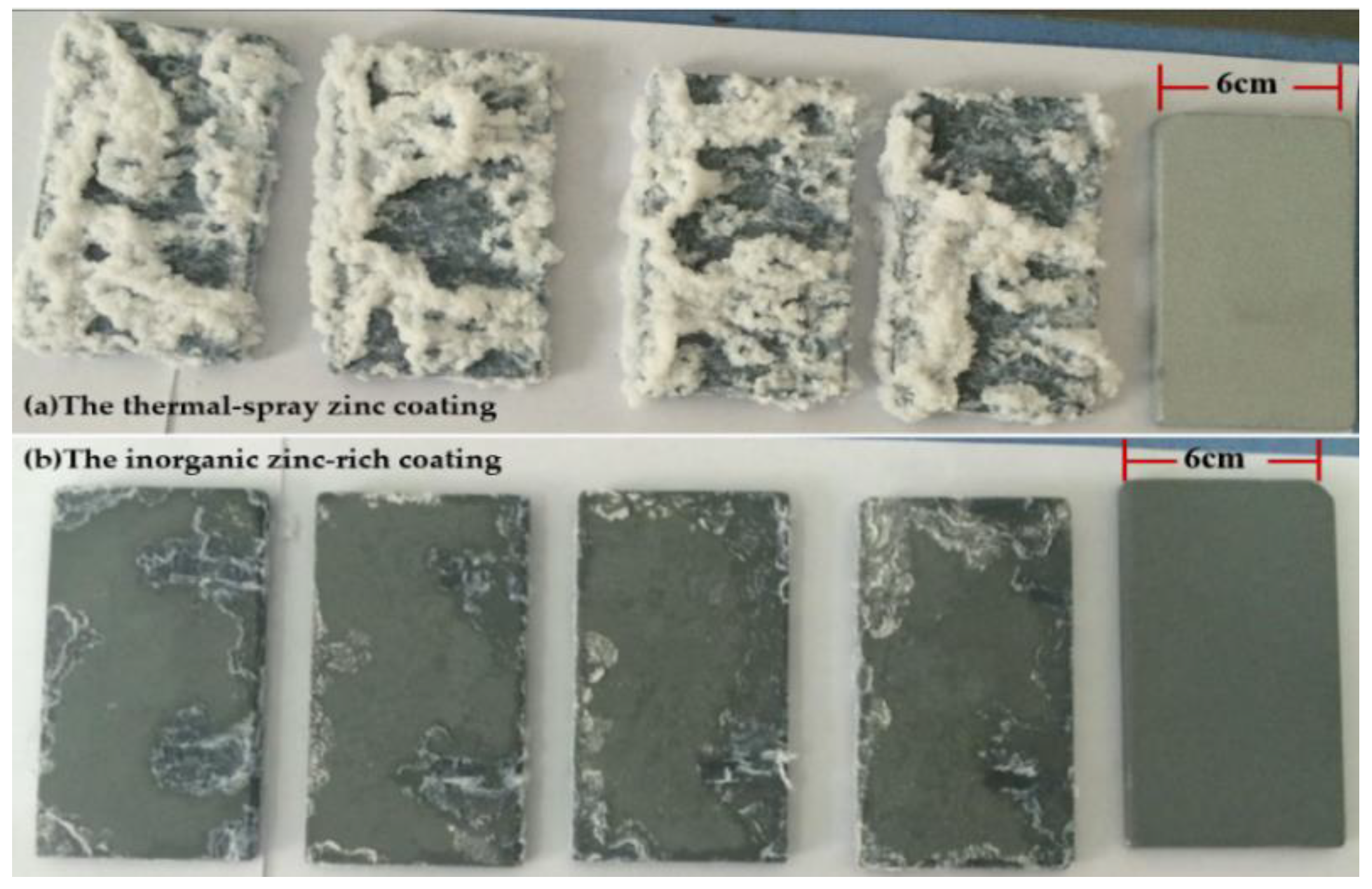
Figure 13—and as shown by the results of SEM and EDS, in the blank sample applied with thermal-spray zinc coating—due to the construction principle and technology, zinc failed to form a continuous and homogeneous coating in the cooling process, resulting in an uneven coating surface. After formation, the inorganic zinc coating was continuous and uniform. As can be seen, spherical zinc is closely arranged and flat, with very low roughness. The high density of the inorganic zinc-rich coatings might be due to the presence of Si–OH in the coating, complexing with zinc atoms, forming a highly dense physical cross-linking network. Therefore, for thermal-spray zinc coatings, permeable corrosive media, such as chloride ions, can quickly penetrate into the thermal-spray zinc coatings and even into the surface of the substrate through the pores, thus accelerating corrosion and increasing damage to the coating; for the inorganic zinc-rich coating, owing to its low porosity, it is difficult for chloride ions to reach the surface of the substrate quickly. This further confirms the conclusion of the AC impedance Nyquist curve—i.e., the thermal-spray zinc began to undergo an oxidation reaction at the interface when the test had just started, while for the inorganic zinc-rich coating, corrosion was not observed until 500 h later. After salt spraying, there were obviously more corrosion defects in the thermal-spray zinc coating, and the contact surface became larger, making the coating more susceptible to corrosion [
18,
19]. After the salt-spray test, the spherical zinc powder on the surface of the inorganic zinc-rich coating disappeared, while the coating remained flat and there were only a few wrinkles on it. According to the results of EDS, after salt spraying, new elements such as aluminum and chlorine came into being, suggesting that new, insoluble corrosion products are indeed formed during the accelerated salt-spray test [
20].
The aluminum element appears in inorganic zinc-rich coating after salt spraying because kaolin is used as filler in the inorganic zinc-rich formula. Kaolin minerals are composed of kaolinite cluster minerals such as kaolinite. The crystal chemical formula of kaolinite is 2SiO
2·Al
2O
3·2H
2O, and its theoretical chemical composition is 46.54% SiO
2, 39.5% Al
2O
3 and 13.96% water. Kaolin is exposed during the process of salt spraying with the corrosion of zinc, and new compounds are chelated in the salt-spray process. Therefore, the characteristic peak of aluminum appears in the EDS test [
21]; however, the amount of such fillers added in the formulation of inorganic zinc-rich coatings is very small. A uniform film surrounded by zinc is formed when the salt spray is not carried out, so there is no aluminum element.
To further analyze the change in the material structure on the coating surface before and after salt-spray treatment, the substance composition of the two coatings before and after corrosion was analyzed.
Figure 14 shows XRD spectra of the untreated surfaces of the thermal-spray zinc and inorganic zinc-rich coatings. According to the results of a comparison with the PDF Database, the composition and the approximate content ratio of the substances on the coating surface are confirmed. Pure zinc and zinc oxide are identified on the surface of thermal-spray zinc coating, with the approximate content ratio of the two substances being as follows: pure zinc: zinc oxide = 95:5. Pure zinc, zinc oxide and quartz are identified on the surface of the inorganic zinc-rich coating, with the approximate content ratio of the two substances being as follows: pure zinc: zinc oxide: quartz = 90:5:5. The inorganic zinc-rich coating sample also contains a small number of impurities (Zn
5(OH)
8Cl
2·H
2O, Zn
4CO
3(OH)
6·H
2O, etc.). This is because the inorganic zinc-rich coating can react with the water and CO
2 in the air, generating a new chemical compound or complex during its own solidification [
22,
23].
Figure 15 shows the results of XRD analysis of the two coating samples after 7500 h of salt spray, with the salt stains freely soluble in water and corrosion products on the coating surface removed lightly with water and a brush. According to the results of a comparison with the PDF Database, the composition and the approximate content ratio of the substances on the coating surface are confirmed. Two kinds of new corrosion products, which are Zn
5(OH)
8Cl
2·H
2O and Zn
4CO
3(OH)
6·H
2O, are identified on the surface of thermal-spray zinc coating, while pure zinc and zinc oxide are not identified on the sample surface [
24]. The possible reason for the missing diffraction peak of pure zinc and zinc oxide is that the coating surface is covered by large amounts of corrosion products due to the high porosity of the thermal-spray zinc coating. Pure zinc, quartz, Zn
5(OH)
8Cl
2·H
2O and Zn
5(OH)
8Cl
2 are identified on the surface of the inorganic zinc-rich coating, with the approximate content ratio of the two substances being as follows: pure zinc: quartz: Zn
5(OH)
8Cl
2·H
2O/Zn
5(OH)
8Cl
2 = 65:2:10.
According to the XRD analysis results of thermal-spray zinc and inorganic zinc before and after salt spray, new corrosion products are formed on the surface of both coatings after the accelerated salt-spray test. Despite a slight difference in the products, the nature of coating oxidation is not changed, i.e., zinc remains oxidized into zinc ions, which are combined with dissolved hydroxide ions and chloride ions, forming insoluble salt. Therefore, the corrosion of the two coatings is the same in essence, and the service life of the inorganic zinc-rich coating can be judged in comparison with that of the thermal-spray zinc coating.
The introduction of a Si–O bond into the inorganic zinc coating formulation, whose bond energy is higher than that of a C–C bond, suggests high stability of the inorganic zinc coating. At the same time, a highly dense chelate is formed on the coating and adhered to the surface of the steel structure, not only reducing the electric conductivity of the system, but also suppressing the diffusion of chloride ions together with the corrosion products. This exerts a shielding effect, thus reducing the corrosion rate of zinc and improving the service life of the coating. According to the electrochemical analysis, the corrosion tendency and rate indicate that the coordination among the corrosion products, porosity and other relevant factors change the micro-current coupling capability; moreover, they exert a shielding effect on the diffusion of chloride ions, thereby reducing the corrosion rate of zinc, with improvement of the corrosion resistance of the coating [
25].
According to the above experimental results, the corrosion mechanism of zinc coating can generally be divided into three stages: In the first stage, “cathodic protection” plays a major role with the shielding of the coating. The change in corrosion potential can be clearly seen from the electrochemical data of 0 to 500 h. It can be inferred that the corrosion medium first contacts zinc during its penetration and diffusion due to the existence of coating porosity. Zinc is sacrificed as an anode to play a role in corrosion resistance. In the second stage, the “cathodic protection” and “corrosion products” interact. At this stage, due to the generation of new corrosion products and the shielding effect of the original coating, it not only reduces the system conductivity, but also inhibits the diffusion of chloride ions together with the corrosion products; this blocks and reduces the corrosion rate of zinc. It can also be seen from the electrochemical experimental data of approximately 2000 h in the manuscript that the corrosion current density of the sample decreases gradually with the extension of time. In this time period, cathodic protection continues to have a leading role in the first stage in the interaction with shielding. In the third stage, “shielding or blocking” plays a leading role. The analysis of electrochemical data after 5000 h shows that the new corrosion products are anchored to the coating surface to form a barrier similar to a passivation layer. As a result, it is difficult for the corrosive medium to penetrate the coating surface. The electrochemical data of the inorganic zinc-rich coating show that some passivation layers even play an isolating role. The corrosion potential of the coating chelated with the corrosion products is even higher than that of the steel substrate. Of course, the shielding stage is still accompanied by cathodic protection. If the shielding layer of the coating is damaged, the cathodic protection will play a leading role again, because the zinc is evenly dispersed in the coating. The period from 2000 h to 5000 h can be called the transition stage, which is from the interaction between cathodic protection and corrosion product shielding to the leading role of shielding.
3.4. Comparison of Thinning Rate between the Two Coatings during Salt-Spray Test and Prediction of the Service Life of the Inorganic Zinc-Rich Coating
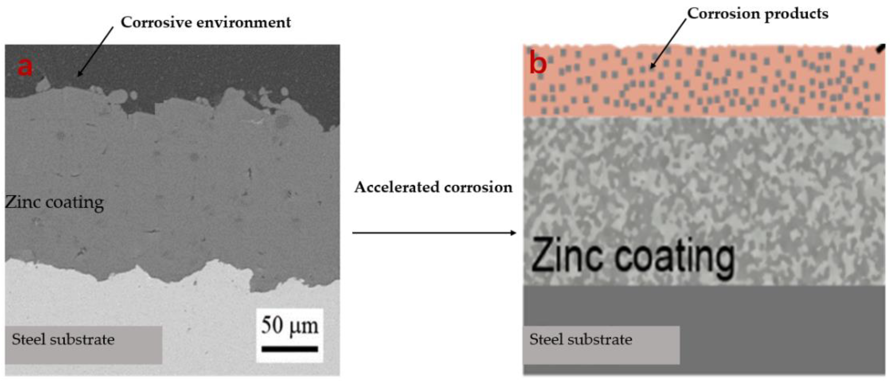
The research object of this paper is the overall coating thickness, i.e., the corrosion thickness is less than the overall coating thickness (as shown in
Figure 16a,b). After the corrosion products are removed, the mass loss of the coating can be obtained. According to the weight-loss data, the life prediction equation of the zinc coating can fitted. The calculation method is as follows: The corrosion rate of the salt-spray sample v = (w1 − w2)/(S * t). According to the calculation formula, the weight-loss data and thinning thickness at each time point were calculated (as shown in
Table 3) and fitted for plotting (v represents the corrosion rate of the sample; w1 and w2 represent the mass loss of the salt-spray sample and the mass loss of the blank sample, respectively; S represents the surface area of the sample; and t represents the salt-spray time).
Considering that the two coatings have a similar corrosion protection mechanism [
26,
27,
28,
29,
30], it is the difference in their composition and structure that causes a difference in the corrosion rate. Although the previous SEM and electrochemical analysis showed that the inorganic zinc-rich coating has higher corrosion resistance, more detailed data are required for the prediction of its service life. After 7500 h of salt-spray testing, the thinning rate of the two coating samples was compared. Additionally, the sets of data were fitted, deriving corrosion rate equations for the two coatings.
Based on the buoyancy method of the Archimedes principle, according to GB/T 9272-2007 (the nonvolatile substance volume fraction of the paint and varnish was determined by measuring the density of the dry coating), the density of the dry thermal-spray zinc is 6.56 g/cm
2, while the density of the dry inorganic zinc-rich coating is 4.171 g/cm
2. These data can be used to calculate the coatings’ thickness thinning. These data points are lineally fitted using mathematical methods based on the thinning data at each time in
Table 1 (the nonlinear least square method based on the Levenberg–Marquardt algorithm (LMA) was adopted for curve fitting) [
31,
32], where units are given in Y/μm and X/h.The following is a fit curve equation for the thickness thinning of the thermal-spray zinc coating:
y = 31.45 × ln(x + 1118.27) − 207.21 [R2 = 0.995]
The following is a fit curve equation for the thickness thinning of the inorganic zinc-rich coating:
y = 13.46 × ln(x + 1339.11) − 98.67 [R2 = 0.989]
As can be seen from the fitting equation in
Figure 17, the thinning data show that under the same accelerated corrosion condition, the thinning rate of the inorganic zinc-rich coating is much lower than that of the thermal-spray zinc coating. According to the data from the anti-corrosion industry, after 4200 h of accelerated salt-spray testing, if the coating is intact and reliable, the coating is basically guaranteed to have a service life of 15–20 years. As shown by the results of the calculation made according to the equation, the thickness of the thermal-spray zinc coating is reduced by 56.04 μm while the thickness of the inorganic zinc-rich coating is reduced by 17.34 μm. The thickness of the conventional thermal-spray zinc coating is about 250 μm and is decreased by 22.4% after corrosion. The design thickness of the inorganic zinc-rich coating is about 100μm and is decreased by 17.3% after corrosion. The thinning data indicate that the requirements of anti-corrosion are easily met. According to the results of the prediction made in the prediction equation, if accelerated salt-spray treatment is adopted on the basis of high coating reliability, it takes about 40 years for the thermal-spray zinc coating to be thinned by 200 μm, while it takes about 40 years for the inorganic zinc coating to be thinned by 75 μm. So, the service life should be greater than 40 years in an actual working environment [
33,
34,
35].
The main reasons for the change in coating thickness with time are as follows: the sacrifice of the anode in a chloride ion corrosion environment leads to the gradual dissolution of zinc. In addition to the dissolution of zinc, the change in coating thickness is also related to the composition of the two kinds of zinc coatings. Silicon-containing compounds are introduced into the formula of the inorganic zinc-rich coating, and the thermal-spray zinc coating is basically composed of a pure zinc compound. Inorganic zinc-rich coating can form stable and dense chelates attached to the surface of a steel structure during the curing of the coating; this not only reduces the conductivity of the system, but also inhibits the diffusion of chloride ions together with corrosion products. Thus, it plays a blocking role, reduces the corrosion rate of zinc and improves the service life of the coating. Combined with the electrochemical analysis, the corrosion tendency and corrosion rate show that the interaction of corrosion products, porosity and other factors changes micro-current coupling ability, provides a barrier for the diffusion of chloride ions, prevents the corrosion rate of zinc, and then provides corrosion resistance to the coating.


