Abstract
The value of face contact pressure has an important influence on the wear life and leakage rate of the mechanical seal. For a long time, people have chosen face contact pressure based on experience and lack of theoretical support, which greatly reduces the effectiveness of the mechanical seal. Based on the percolation theory, the critical porosity of zero-leakage at the wetting and non-wetting sealing interface working in liquid medium is first discussed. The influence of end-face frictional heat on end-face friction and wear is then investigated. The design criteria for the face contact pressure of mechanical seals with zero-leakage and long-life operation are established. Afterwards, the face contact pressure range of the mechanical seal working in conventional different liquid medium is calculated, and the influence of different working conditions on the face contact pressure range change is analyzed. Existing studies have shown that mechanical seals can achieve zero-leakage and long-life operation. Under the rotating and stationary rings’ physical parameters and given working conditions, the face contact pressure range of the sealing medium water and propane propylene is 0.477~1.132 MPa. The diesel sealing medium has a larger face contact pressure range than that of water and propane propylene, which can reach 0.477~2.183 MPa. The working condition speed, medium temperature, and medium pressure have an influence on the face contact pressure range, while the influence of the working condition speed is the most significant.
1. Introduction
Mechanical seal is the main shaft seal form of rotating equipment such as centrifugal compressors, centrifugal pumps, steam turbines, etc. Its performance parameters include the leakage rate and wear life [1]. Besides the working condition parameters, the mechanical parameter of the face contact pressure is the most critical factor affecting the mechanical seal performance [2]. Increasing the face contact pressure is beneficial in reducing the porosity between the sealing interface and achieving zero leakage. However, excessive face contact pressure will increase the wear of the sealing interface and shorten the service life of the mechanical seal [3,4]. For this reason, many researchers have conducted in-depth explorations on the selection principle of face contact pressure.
For instance, Mayer [5] defined the face contact pressure as the resultant axial force acting on the unit sealing surface area, including the liquid film force and the asperity bearing capacity. He mentioned that the leakage rate is inversely proportional to the square of the face contact pressure, and the amount of wear increases with the increase of the contact pressure. Lebeck [6] and Gu [7,8] clarified from a microscopic point of view that the face contact pressure is only the contact bearing capacity of the asperity per unit nominal sealing surface area, which is equal to the product of the compressive strength of relatively weak material and the ratio of the bearing area of the asperity. Salant et al. [9] used the plastic contact model by assuming that the asperity height distribution on the end face is Gaussian. They determined the contact pressure at any radius on the contact face. Based on the GW model, Elhanafi et al. [10] developed a contact load expression for a flat surface and a rough surface with Gaussian distribution of asperity height. Sun et al. [11] and Li et al. [12] used fractal parameters independent of the measurement scale to describe the cross-sectional profile of microchannel, which solved the problem that the size of microchannel interface changes with contact pressure. These studies have contributed to the safe operation of mechanical seals. However, gaps or microchannels at the sealing interface under operable contact pressure still exist. It is impossible to explain the zero-leakage and long-period operation of the mechanical seals, such as the main pump and the refrigeration compressor of the sodium-cooled fast reactor, for example. In fact, the sealing interface is composed of the rotating and stationary ring surfaces obtained by machining. In addition, although voids exist, the size of the void ratio can be controlled by applying contact pressure, ensuring that there is no percolation at the sealed interface, and achieving zero leakage [13]. Therefore, determining the best face contact pressure range is the key to achieving zero-leakage and long-life mechanical seal operation.
This paper intends to start from the zero-leakage of the sealing interface, based on the percolation theory, to discuss the critical porosity of the wetting and non-wetting sealing interface in liquid media. The temperature rise of the sealing interface caused by frictional heat and the resulting deep wear rate are investigated. The requirements of zero-leakage rate and wear rate not exceeding the standard are combined to determine the range of the seal face contact pressure and establish the theoretical basis for the design of the seal face contact pressure. Consequently, the face contact pressure range of the conventional sealing medium, clean water, diesel, and propane propylene, is calculated and analyzed.
2. The Critical Porosity at Zero Leakage
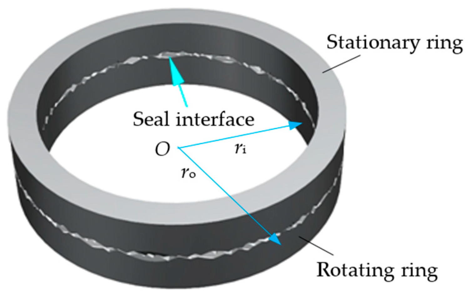
Figure 1 is a schematic diagram of the sealing interface composed of the rotating and stationary ring, where ri and ro are the inner and outer radius of the sealing surface, respectively. In the initial state or the process of wear, there are always asperity contact and gaps in the sealing interface [14,15]. According to the percolation theory (seen in Appendix A), when the porosity of the sealing interface reaches the percolation threshold, microchannels penetrating the sealing surface at the sealing interface will appear [16]. When the porosity is less than the percolation threshold, the sealing interface is in a non-percolation state and no microchannels exist. However, whether there should be fluid flow at the sealing interface in the percolation state depends on whether the driving force on both microchannel sides is greater than the resistance of the fluid to flow [17].
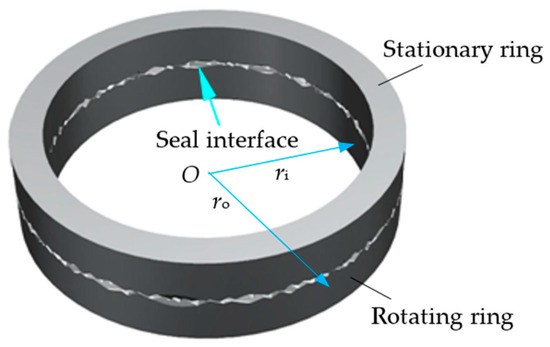
Figure 1.
Schematic diagram of the rotating and stationary ring sealing interface.
The wettability of the sealed medium to the rotating and stationary ring materials is different. The effect of the capillary force formed in the microchannel on the sealing interface is also different [18].
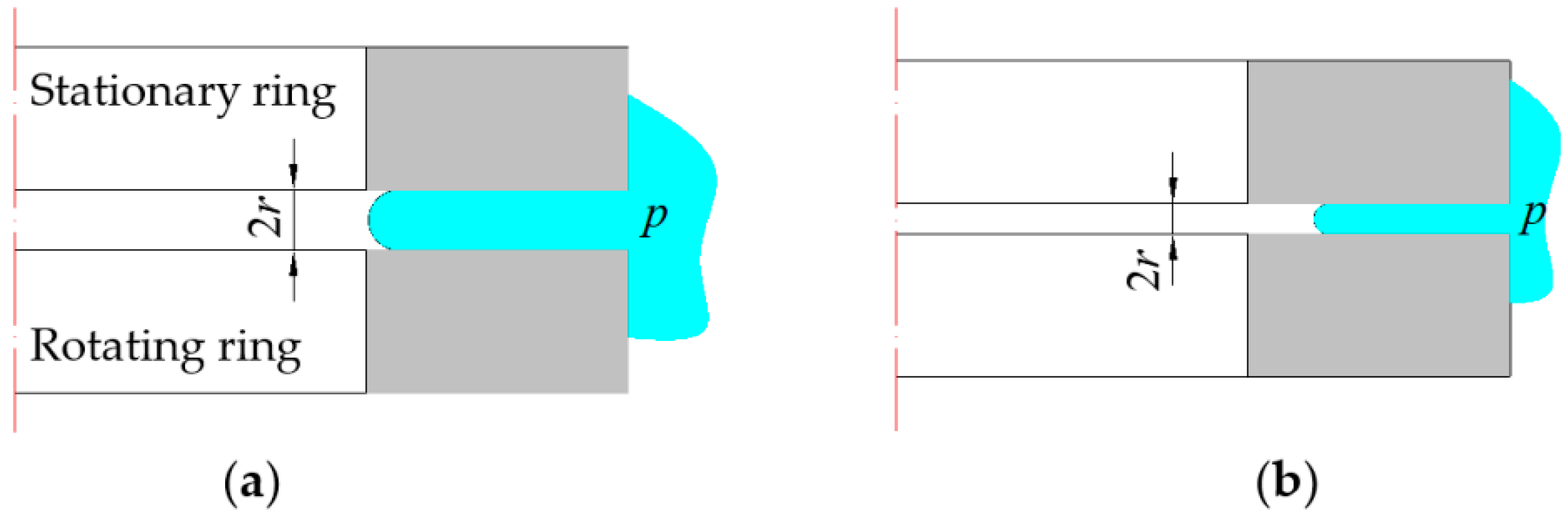
For the sealing interface composed of rotating and stationary ring materials that cannot be wetted, the capillary force formed by the sealing medium in the microchannel prevents the leakage of the sealed medium [4]. To ensure that the sealed medium exists in the sealing interface to achieve lubrication, while not leaking from the microchannel, it is necessary to control the size of the microchannel pore. Increasing the face contact pressure can reduce the porosity of the sealing interface, reduce the radius of the void capillary, increase the capillary force, and improve the leakage resistance of the sealing interface [3], as shown in Figure 2. That is, it can be seen from Figure 2 that when the face contact pressure increases, the asperities of the sealing interface will be further deformed, and the microchannels between the sealing interfaces will change from large-diameter microchannels to small-diameter microchannels.
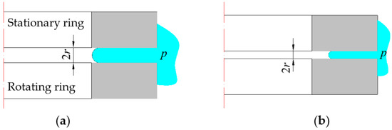
Figure 2.
Schematic diagram of the rotating and stationary ring sealing interface. (a) Large diameter microchannel; (b) Small diameter microchannel.
The relationship between the capillary driving pressure of the microchannel at the sealing interface and the radius of the microchannel r can be derived from the interface Laplace Equation [19]:
where p is the capillary upper and lower liquid level driving pressure, ζ represents the surface tension of the liquid, φ denotes the contact angle, and r is the radius of the microchannel.
When p is the medium pressure, rc is the critical radius of the zero-leakage microchannel. The porosity maintained by the sealed interface of the microchannel with a critical radius is the critical porosity, in the case of zero leakage. To ensure zero leakage, it is necessary to guarantee that the pore size of the microchannel at the sealing interface is smaller than the critical radius rc of the zero-leakage microchannel.
For the rotating and stationary ring face materials that can be wetted by the sealing medium, there should be no microchannels at the sealing interface, because the capillary force will push the sealed medium to leak. To ensure zero leakage, according to the percolation theory (Appendix A), it can be known that it is necessary to control the porosity ϕ of the sealing interface to be less than the percolation threshold of 0.312 [16].
3. Theoretical Analysis of Wear Rate of Sealing Interface
Increasing the face contact pressure improves the sealing performance of the sealing interface. It also increases the friction of the sealing interface [20]. The generation of frictional heat and the increase of the end surface temperature degrade the performance of the rotating and stationary ring materials, making the end faces of the stationary ring more prone to adhesive wear and bringing the risk of excessive wear rate to the mechanical seal [21].
3.1. Calculation of the Sealing Interface Frictional Heat
Under the action of end face load, the thermal strength of the sealing interface due to friction is expressed as [6]:
where ri and ro are the inner and outer radius of the sealing surface, respectively, pg represents the specific load of the end face such that pg = pc + pm, pc denotes the face contact pressure, pm is the fluid film pressure on the end face, U is the linear velocity of the middle diameter of the sealing surface, and f is the total friction coefficient of the sealing interface given by:
where W is the end face load such that W = pg·Aa, Aa represents the nominal contact area of sealing surface, β = 2π(hφ0 − δ)/(h − δ), h denotes the fluid film thickness in the non-contact zone of the sealing interface, δ is the compression of the asperity under the action of pc, μ is the fluid viscosity, and fc is the adhesive friction factor.
When the asperities of the sealing interface are in elastic contact, the adhesive friction factor fc can be computed as:
where α is the component of the asperities contact area which can be determined as in [22], τc represents the average value of the dry friction shear strength, E* denotes the composite elastic modulus of the rotating and stationary ring, σ is the equivalent surface mean square error of asperities [6] such that , and β* is the composite correlation length of the asperity [23] generally equal to 0.8 mm [24].
When the asperities of the sealing interface are in a plastic contact state, the adhesion friction factor fc can be calculated as:
where Hs is the material hardness of the softer ring in the sealing interface matched ring.
When the asperities of the sealing interface are in an elastic–plastic contact state, the adhesion friction factor fc can be computed as:
where f(a) is the template function given by [25]:
where aec and apc are the critical area of the asperity elastic deformation and plastic deformation, respectively.
3.2. Calculation of the Sealing Interface Temperature
The frictional heat generated by the friction of the sealing interface satisfies the classical equation of isotropic solids heat conduction [26]:
where T is the temperature rise, K represents the thermal conductivity, ρ denotes the density, cp is the specific heat capacity at constant pressure, t represents the time, Q/V denotes the internal heat generation, V is the volume, and Q is heat release, Q = dt.
Assuming there is no heat exchange between the rotating and stationary ring and the outside world, and the frictional heat is distributed between the two rings as χh:(1 − χh), the sealing interface with different contact stresses will obtain different temperature rises [27].
Under the action of high contact stress, that is, when the specific load pg of the end face is close to the hardness Hs of the weaker material or Ar/Aa ≈ 1, the contact and friction heat of the rotating and stationary ring relative to high-speed sliding (Peclet number L = Ul/κ > 10) and low-speed sliding (L < 0.5) are uniform. The temperature rise of the end face is given by [24,27]:
When sliding at high-speed (Ul/κ > 10):
where , and κ is the thermal diffusivity equal to .
When sliding at low-speed (Ul/κ < 0.5):
where q is the heat flux density, q = , l is the half-width of the rectangular heat source in the x direction (l = π(ri + ro)/2 for mechanical seal rings), and b is the half-width of the sealing surface.
The contact and frictional heat formed on the sealing interface are not uniform in the relative sliding of the rotating and stationary ring under low contact stress (Ar/Aa << 1) [28]. The rotating and stationary ring sealing interface, formed by the matching of different surface roughness, have different temperature rises during relative sliding.
- (1)
- Calculation of the sliding temperature rise with roughly equivalent surface roughness
When sliding at high-speed (3 Udmax/16κ > 10):
When sliding at low-speed (Ul/κ < 0.5):
where , dmax is the maximum contact diameter of the asperities, and ψ is the area coefficient of the heat source equal to 1.12 [27].
- (2)
- Calculation of sliding temperature rise between rough surface and flat surfac.
When sliding at high-speed ():
When sliding at low-speed (Ul/κ < 0.5):
where is the average diameter of the asperity, Aam/n(a)a can be used to obtain the contact surface area of a single asperity, is then used to find , where Aam is the calculated nominal area given by:
where d is the bottom diameter of the largest asperity and D denotes the fractal dimension of the sealing end surface.
Note that n(a)a represents the number of asperities, which can be expressed as:
3.3. Calculation of the Wear Rate of the Sealing Interface
According to the obtained temperature rise of the sealing interface, the material hardness Hs of the soft ring at different temperatures can be determined. Next, use the face contact pressure pc to judge the contact state of the seal end face contact pair (the method for judging the contact state of the contact pair under different face contact pressure pc can be found in reference [16,21]) so as to select the corresponding deep wear rate calculation formula to calculate the size of the deep wear rate of the sealing interface.
For plastic contact, the wear rate is given by [29]:
where k is the wear coefficient, as the mechanism of temperature’s influence on the wear coefficient is very complicated. For the convenience of calculation, the wear coefficient k is only taken at 37 °C; J(θmax) is a function used to describe the corresponding relationship between the end surface temperature rise θmax and the hardness Hs of the soft ring material. When the end surface temperature rise θmax takes different values, and the soft ring material will have different hardness Hs corresponding to it.
For elastic contact, the wear rate is expressed as [27]:
where M(θmax) is the characterization function, which is used to characterize the functional relationship between the composite elastic modulus E* and the end face temperature rise θmax, when θmax takes different values, the corresponding composite elastic modulus E* will be obtained.
For elastic–plastic contact, the wear rate is given by:
4. Design Criteria for Face Contact Pressure
4.1. Design Criteria
To achieve the zero-leakage and long-life operation of the mechanical seal, the microchannel radius of the sealing interface should be smaller than the critical radius of the zero-leakage microchannel, or no microchannel should exist. Simultaneously, it should meet the wear rate requirement ( < 0.02 mm/100 h) [30].
The radius of the microchannel is smaller than the critical radius of the zero-leakage microchannel, which is achieved by controlling the seal face contact pressure. The change of the face contact pressure affects the porosity of the sealing interface, the formation of the microchannel, and its radius scale [31]. In addition, the face contact pressure increases, the porosity of the sealing interface decreases, the radius of the microchannel decreases, and even no microchannel exists [16]. Continue to increase the face contact pressure to compact the sealing interface so that the porosity is zero [16,32]. However, the porosity decrease will reduce the fluid film of the sealing interface, increase the frictional heat, decrease the material performance, and increase the wear rate. When the wear rate is greater than 0.02 mm/100 h, the wear of the sealing interface exceeds the standard.
In summary, the following design criteria for the face contact pressure of mechanical seal can be established in this paper.
(1) For the wettable sealing interface, the sealing interface needs to ensure that there is no leakage of microchannels and the wear rate does not exceed the standard, that is,
where ϕ is the porosity of the sealing interface under the action of pc, which can be calculated by the following formula:
where h is the fluid film thickness in the non-contact zone of the sealing interface; ϕ0 is the initial porosity of the sealing interface; δ is the compression of the asperity under the action of pc
where G is the scale factor of the sealing interface.
However, with the continuous increase of the face contact pressure pc, the asperities contact state of the sealing interface will experience three stages: elastic deformation, elastic–plastic deformation and plastic deformation. There is a different functional relationship between the face contact pressure pc and the contact area of the asperities under different contact states, which can be seen in references [16,22,31]. Given pc, the corresponding contact area a of the asperity can be obtained, and then the compression amount δ of the asperity can be obtained from Equation (24). Finally, the porosity ϕ under different face contact pressures pc can be determined by Equation (23).
Taking into account the complex relationship between the end contact pressure pc and the porosity ϕ, the characterization function N(pc) is now set to characterize the complex relationship, namely:
ϕ = N(pc)
Substituting Equations (23) and (25) into Equation (22), the design criterion for the face contact pressure under this condition is:
(2) For the non-wettable sealing interface, when the sealing interface is in a non-percolation state (ϕ < 0.312), the design criterion for the face contact pressure is the same as Equation (26); when the sealing interface is in a percolation state (ϕ > 0.312), the design criterion for the face contact pressure is that the radius of the microchannel of the sealing interface should be smaller than the critical radius of the non-leakage microchannel and the wear rate should not exceed the standard, that is
where r is the radius of the microchannel at the sealing interface, r = (h − δ)/2; rc is the critical radius of the non-leakage microchannel at the sealing interface, which can be obtained by Equation (1):
where ps is the pressure of the sealing medium.
In the same way, since r = (h − δ)/2, if you want to find the microchannel radius r, you need to first obtain the compression δ of the asperity by Equation (24). Therefore, the characterization function S(pc) can be set to characterize the complex relationship between the face contact pressure pc and the microchannel radius r, namely:
r = S(pc)
Substituting Equations (23), (28) and (29) into Equation (27), the design criteria for the contact pressure of the end face under this condition is:
It is worth noting that the design criterion Equation (26) for the face contact pressure of the wettable sealing interface is in a non-percolation state (ϕ < 0.312). However, in the percolation state (ϕ > 0.312), there is a leakage channel at the wettable sealing interface but zero leakage of the mechanical seal can still be achieved, although this paper does not discuss it; the zero-leakage mechanism in this state is related to the interaction between fluid molecules, hydrodynamic and static pressure mechanisms, fluid shear, etc. The design criteria for face contact pressure in this state needs to be further studied in the future.
4.2. Calculation Process
Equations (26) and (30) present the design criteria for the face contact pressure of mechanical seals, with two different wetted surfaces under the permissible wear rate ( < 0.02 mm/100 h) in the case of zero-leakage. It is important to mention that the porosity and microchannel radius r are negatively correlated with pc, while the wear rate is positively correlated with pc. Therefore, Equation (26) or Equation (30) can be used to determine the face contact pressure range of the mechanical seal during zero-leakage operation under the allowable wear rate: pcmin~pcmax.
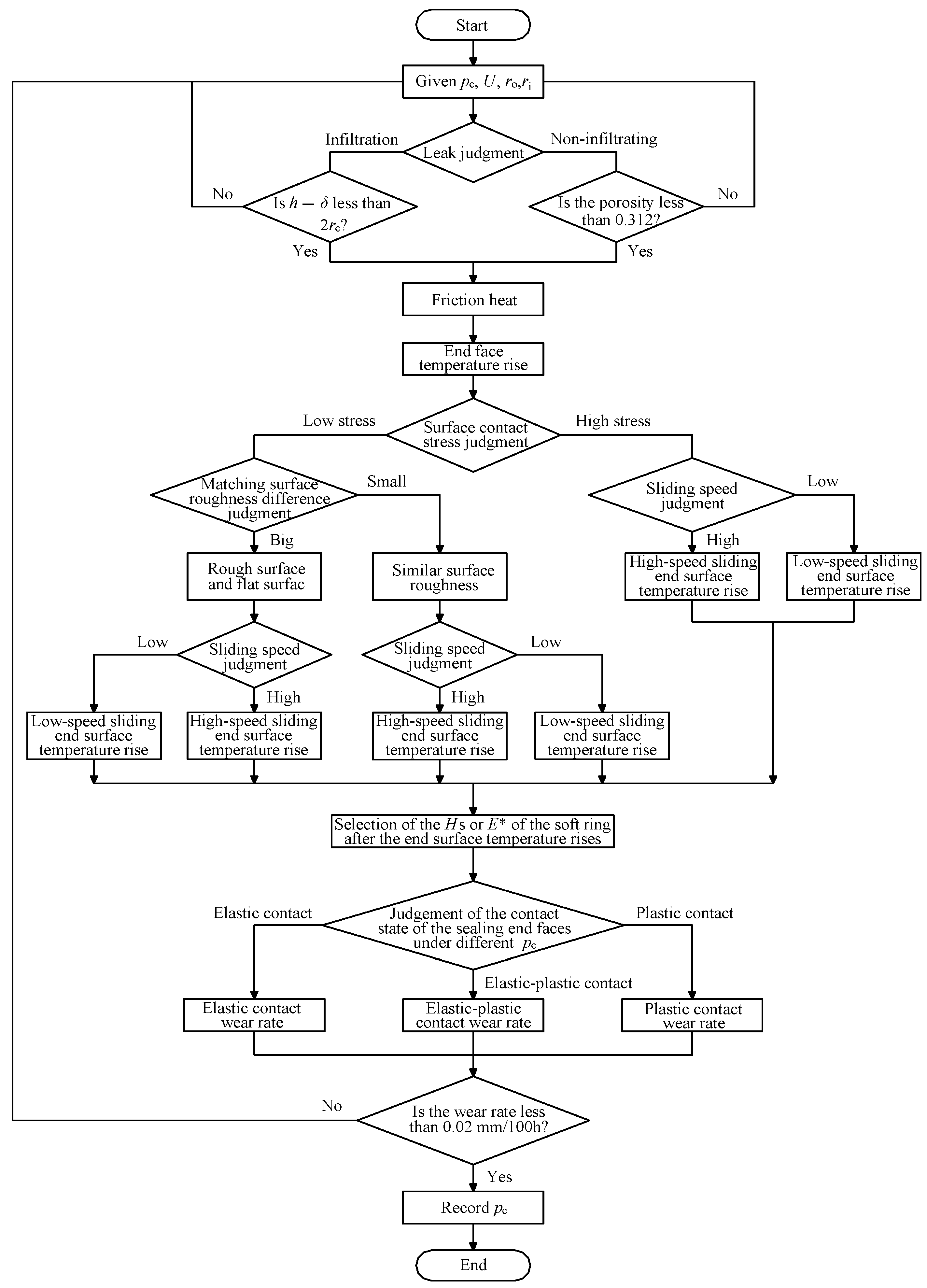
Figure 3 shows the specific solution flow of the face contact pressure range under the zero-leakage and long-life operating state developed in this paper.
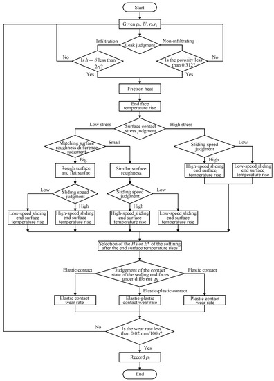
Figure 3.
Solution process of the face contact pressure range.
5. Calculation Example
The rotating ring (SiC) and stationary ring (M106K), commonly used in mechanical seals, are selected. Based on the previously developed theoretical basis, the wettable sealing interface formed by several commonly used liquid mediums is investigated in the wear rate of < 0.02 mm/100 h, and a value range of the face contact pressure of different sealing mediums in zero-leakage operation. The change of the face contact pressure range under the different working conditions of speed, medium temperature, and medium pressure is also analyzed.
5.1. The Face Contact Pressure Range of the Conventional Sealing Medium
Table 1 shows the physical property parameters of the sealing medium clean water, diesel oil, and propane propylene at 37 °C with a medium pressure of 1.275 MPa [1]. Table 2 shows the structural parameters of the rotating and stationary ring, and their related material performance parameters [1,5,33].

Table 1.
Physical parameters of several commonly used sealing mediums.
Table 2.
Structural parameters and material performance parameters of the rotating and stationary ring.
It is important to mention that, as long as one surface can be wetted, the capillary force of the microchannel at the sealing interface will become the driving force for leakage. The sealing interface is composed of the selected sealing medium and the rotating and stationary ring, which is a surface that can be wetted. Therefore, to ensure that there is no leakage at the sealing interface, there should be no microchannels at the sealing interface. That is, the porosity of the sealing interface should be controlled to be less than the percolation threshold of 0.312.
The initial operating speed and the medium temperature are respectively set to 3000 r/min and 37 °C. The size of the end face wear coefficient when the sealing end face is matched with different sealing media can be obtained from the reference [1], while the data of Table 1 and Table 2 are used for the other relevant parameters. The face contact pressure range of the sealing medium clean water, diesel oil, and propane propylene under the allowable wear rate ( < 0.02 mm/100 h) and the sealing interface zero-leakage operation are obtained by calculation. The calculation results are shown in Figure 4.
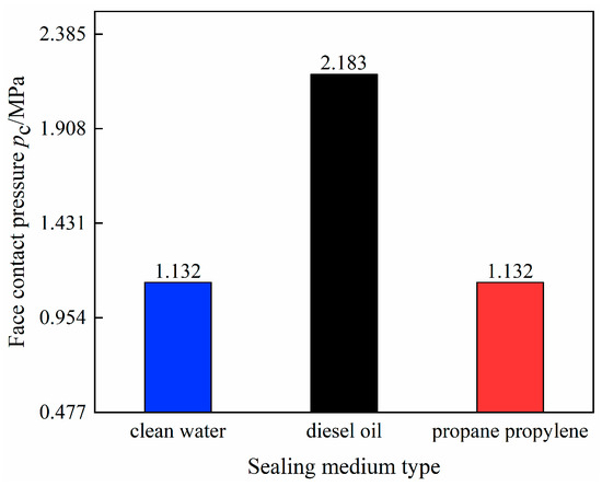
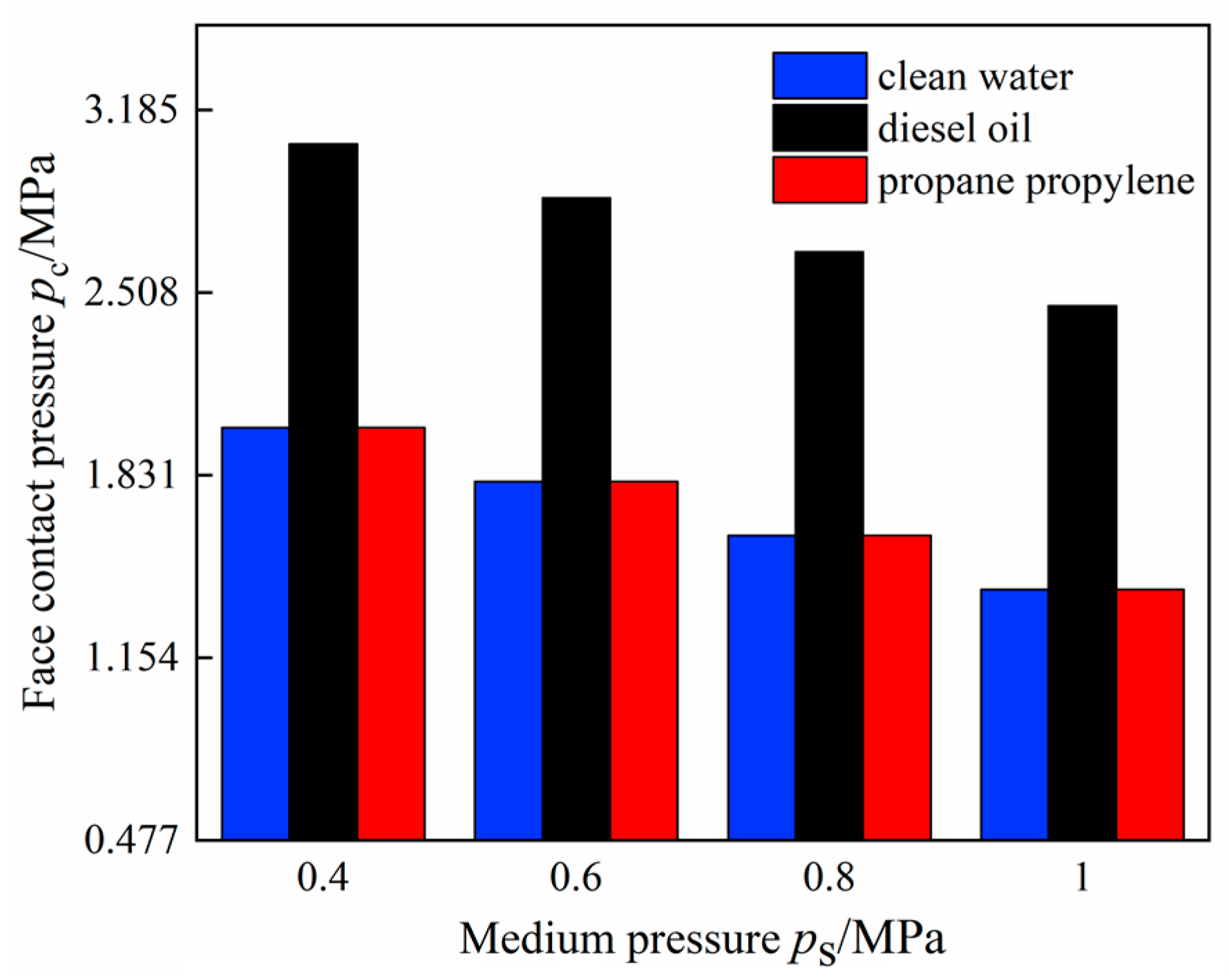
Figure 4.
The face contact pressure range of different sealing media.
It can be seen from Figure 4 that the face contact pressure range of clean water and propane propylene is 0.477~1.132 MPa. The face contact pressure range of diesel oil is 0.477~2.183 MPa, which is greater than that of clean water and propane propylene. In other words, under this working condition, diesel oil can provide a more relaxed face contact pressure selection space to ensure the zero-leakage and long-life operation of the mechanical seal under the permissible wear rate. In addition, it can be seen that the lower limit pcmin of the face contact pressure range of clean water, diesel oil, and propane propylene is 0.477 MPa. Moreover, when the material of the rotating and stationary ring and the surface morphology parameters are determined, the minimum face contact pressure pcmin corresponding to the zero-leakage condition of the sealing interface is found, and it has nothing to do with the sealing medium.
5.2. The Influence of the Working Condition Parameters on the Face Contact Pressure Range
The same calculation method is used to compute the face contact pressure while changing the operating speed and fixing the other conditions. The calculation results are shown in Figure 5. It can be observed that, as the speed increases, the face contact pressure ranges of the three-sealing mediums show a rapid shrinking trend. When the rotation speed reaches 4000 r/min, the face contact pressure range of clean water and propane propylene becomes very narrow (0.477~0.530 MPa). In addition, under high-speed working conditions, the higher the lubrication performance of the sealing medium, the larger the obtained space of the face contact pressure range. This creates favorable conditions for the zero-leakage and long-life operation of the mechanical seal under the allowable wear rate.
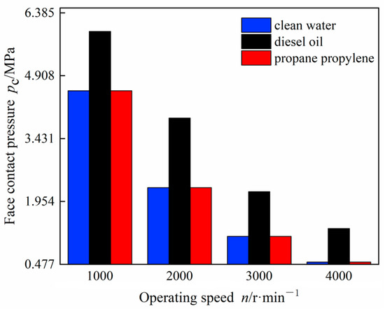
Figure 5.
Influence of the operating speed on the face contact pressure range.
Figure 6 shows the variation of the face contact pressure range function of the pressure of the sealing medium while the other conditions are fixed. It can be seen that the increase in media pressure has the same influence on the face contact pressure range of the three-sealing media, which is embodied in the continuous reduction of the face contact pressure range when the medium pressure increases. By comparing Figure 5 and Figure 6, it can be deduced that the influence of the medium pressure on the face contact pressure range is lower than that of the operating speed.

Figure 6.
Influence of the medium pressure on the face contact pressure range.
Figure 7 shows the influence of the medium temperature change on the face contact pressure range. It can be seen that when the medium temperature varies between 35 and 80 °C, the face contact pressure ranges of the clean water and diesel oil show a shrinking trend, while the reduction of diesel oil is more obvious. This is because the lubrication performance of diesel oil is more susceptible to temperature than clean water, which results in increasing the wear coefficient of the sealing interface. In addition, the face contact pressure range of propane propylene is almost unchanged. Moreover, the influence of the medium temperature on the face contact pressure range is mainly affected by the change of the sealing medium lubrication performance. As the temperature increases, the lubrication environment between the seal interfaces deteriorates and the wear intensifies, which limits the face contact pressure range.
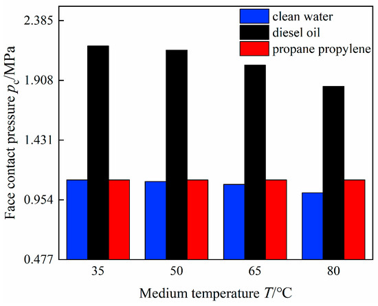
Figure 7.
Influence of the medium temperature on the face contact pressure range.
6. Conclusions
- The critical porosity in the case of zero-leakage at the sealing interface varies with the wettability of the sealed medium to the rotating and stationary ring materials. For the rotating and stationary ring that can be infiltrated by the sealing medium there should be no microchannels at the sealing interface, with a critical porosity of 0.312. On the contrary, for the rotating and stationary ring that cannot be infiltrated by the sealing medium, there may be microchannels on the sealing interface, and the critical porosity is when the percolation point size is equal to the critical diameter of the microchannel.
- The wear rate is related to the temperature increase of the end face and the contact properties of the asperity. The asperity on the sealing interface is generally in an elastic–plastic contact state. Its adhesive friction coefficient or wear rate can be characterized by the relationship between the friction coefficient or wear rate of elastic contact and plastic contact as well as the template function.
- A design criterion of the face contact pressure of zero-leakage mechanical seal is developed. The face contact pressure is well controlled, and the zero-leakage and long-life operation of the mechanical seal can be performed.
- This paper does not take into consideration the case where a leakage channel at the wettable seal interface exists while the zero-leakage of the mechanical seal can still be achieved, leaving this perspective an open discussion for future considerations.
Author Contributions
Funding acquisition, J.S.; Methodology, C.M.; Software, Q.Y.; Supervision, J.S.; Writing—original draft, W.Z.; Writing—review & editing, W.Z. All authors have read and agreed to the published version of the manuscript.
Funding
The research was funded by the National Natural Science Foundation of China [grant number 52075268] and the Key R&D Projects of Jiangsu Province [grant number BE2021062].
Institutional Review Board Statement
Not applicable.
Informed Consent Statement
Not applicable.
Data Availability Statement
Data sharing is not applicable to this article.
Conflicts of Interest
The authors declare no conflict of interest.
Appendix A
The surface of the rotating and stationary ring of the mechanical seal in the initial state or the process of wear is uneven under the microscope, as shown in Figure A1. When the rough surfaces of the rotating and stationary ring are in contact, they form an extremely thin sealing interface with gaps between the length, width, and height [14,34]. To facilitate the description of the gap distribution of the rotating and stationary ring sealing interface, the sealing interface can be divided into several grid micro-cubes. Assuming that there are n layers in the height of the sealing interface, and each layer has m × m grid microcubes, the sealing interface is composed of m × m × n grid microcubes.
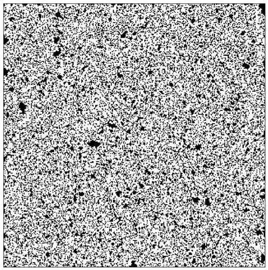
Figure A1.
The surface morphology of the sealing interface under the microscope.
Figure A1.
The surface morphology of the sealing interface under the microscope.
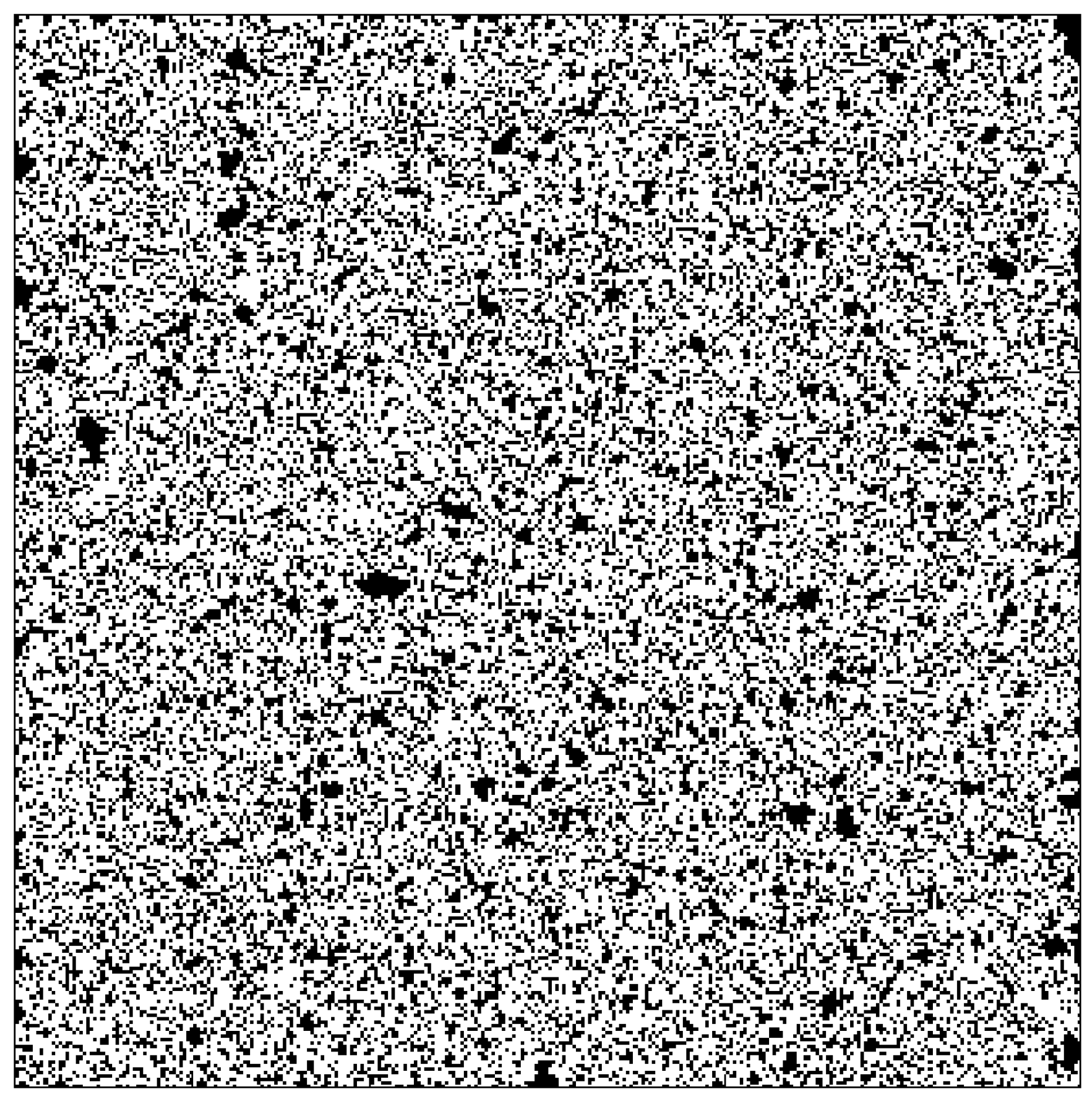
Figure A2 is a schematic diagram of the change of the gap-skeleton of the single-layer grid sealing interface. Among them, the black cube represents the asperity skeleton area, and the white cube represents the gap area. Assuming that the probability that the microcube is a gap is Pp, which is the porosity ϕ, the probability of the skeleton is 1 − Pp = 1 − ϕ, and the microcubes do not affect each other. Percolation theory believes that [34], the size and distribution of the group is a function of the porosity; as the porosity increases, the average size of the gap group also increases. Once the porosity reaches a specific critical value ϕc, this gap group will penetrate both sides of the sealing interface to form leaky microchannels, that is, when ϕ = ϕc, the group percolates. The critical porosity ϕc is called the percolation threshold. When ϕ < ϕc, the gap group will not penetrate both sides of the sealing interface; when ϕ > ϕc, the sealing interface is completely percolated, that is, not just a few percolation points, but a large group of gaps with a large number of dots in the middle skeleton fragments.
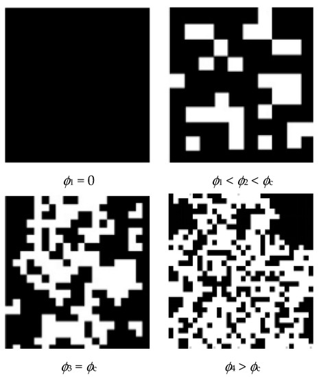
Figure A2.
Single-layer grid sealing interface gap-schematic diagram of skeleton change.
Figure A2.
Single-layer grid sealing interface gap-schematic diagram of skeleton change.
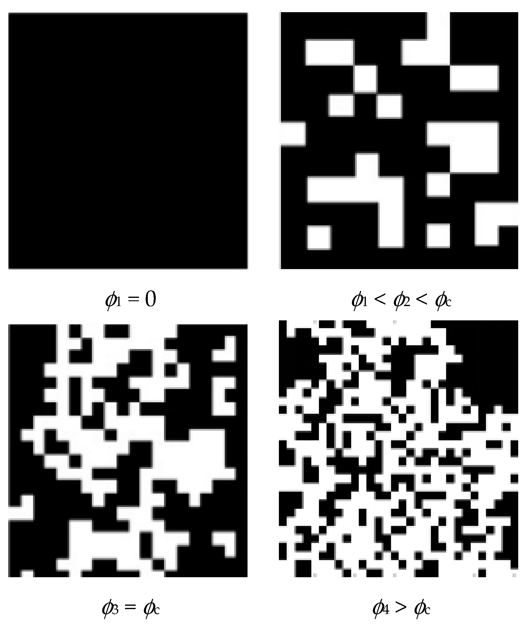
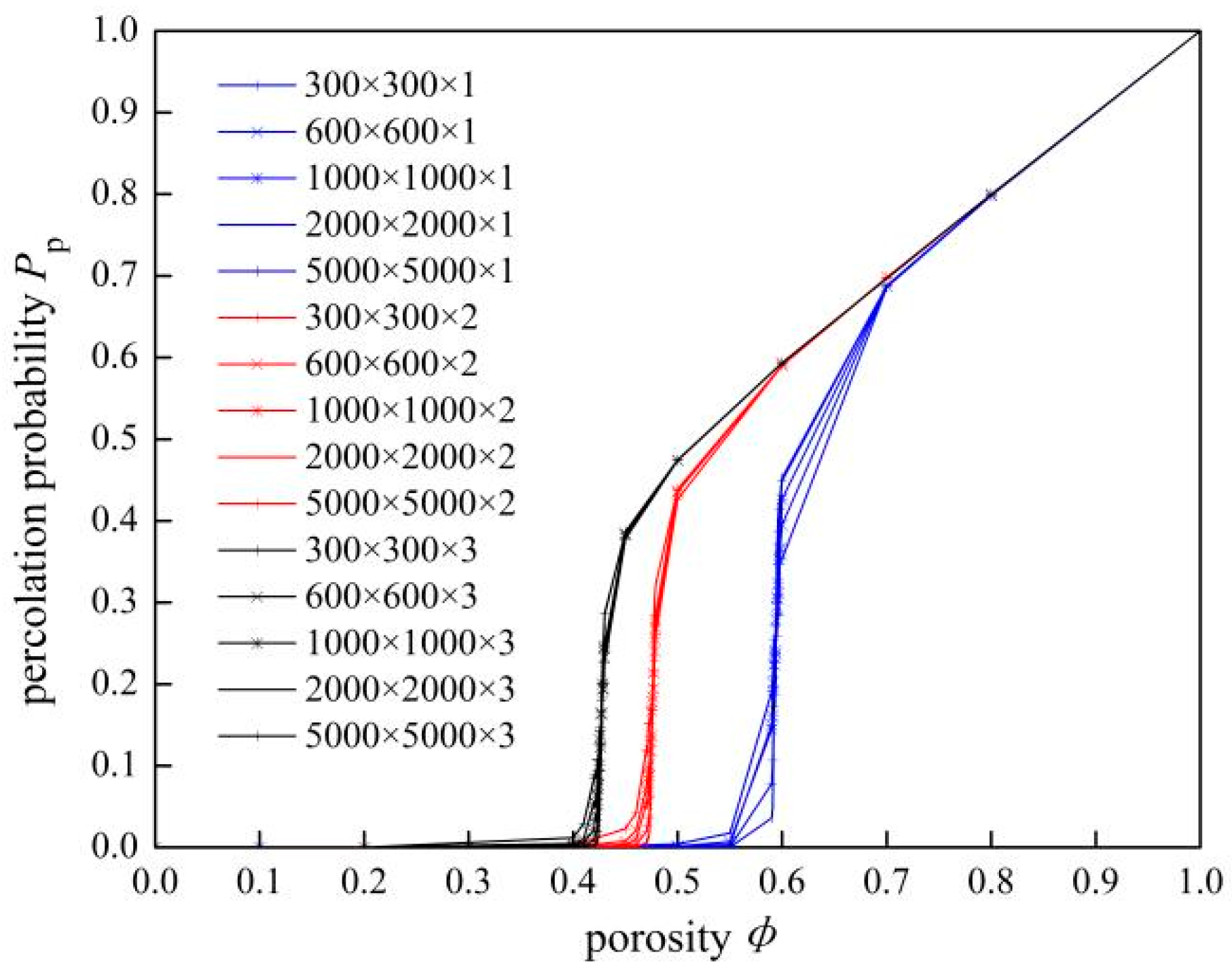
Figure A3 depicts the percolation threshold of the sealing interface with a regional change of [300 × 300, 5000 × 5000] and heights of 1, 2, and 3 layers of grids. The percolation threshold corresponding to the sealing interface of the 1, 2, and 3 grids are respectively ϕc1 = 0.593, ϕc2 = 0.475 and ϕc3 = 0.425; when the number of grid layers of the sealing interface n > 300, ϕcn = 0.312 [34]. With the increase of the number of grid layers, the percolation threshold of the sealing interface decreases. That is, if the sealing interface is divided into 2 or 3 layers, the new percolation threshold will no longer be 0.593 under the single-layer grid, but ϕc2 = 0.475 and ϕc3 = 0.425 which are less than this value, and the percolation point size of the corresponding sealing interface will also become smaller. For a certain sealing interface, the size of the gap on it does not change with the number of layers divided by the grid, but the gap under the single-layer grid becomes a gap composed of multiple small grids when the multi-layer grid is divided.

Figure A3.
The percolation threshold of the sealing interface under different layers of grids.
Figure A3.
The percolation threshold of the sealing interface under different layers of grids.
References
- Hao, M. Mechanical Seal Technology and Application, 1st ed.; China Petrochemical Press: Beijing, China, 2010; pp. 12–31. [Google Scholar]
- Sun, J.J.; Ma, C.B.; Yu, Q.P.; Lu, J.H.; Zhou, M.; Zhou, P.Y. Numerical analysis on a new pump-out hydrodynamic mechanical seal. Tribol. Int. 2017, 106, 62–70. [Google Scholar]
- Du, P.Y.; Sheng, J.; Li, J. Analysis of factors affecting the specific pressure of mechanical seals. J. Beijing Inst. Petrochem. Technol. 2013, 21, 22–25. [Google Scholar]
- Sun, J.J.; Chen, G.Q.; Ji, Z.B.; Ma, C.B. Analysis of interface leakage mechanism of contact mechanical seal. CIESC J. 2018, 69, 282–290. [Google Scholar]
- Mayer, E. Mechanical Seals, 1st ed.; Chemical Industry Press: London, UK; Newnes-Butterworth: London, UK, 1997; pp. 21–43. [Google Scholar]
- Lebeck, A.O. Principles and Design of Mechanical Face Seals, 1st ed.; A Wiley-Interscience Publication; John Wiley & Sons, Inc.: New York, NY, USA, 1991; pp. 51–67. [Google Scholar]
- Gu, Y.Q. The selection principle of mechanical seal specific pressure. Petrochem. Equip. 2000, 29, 21–24. [Google Scholar]
- Gu, Y.Q. Calculation of the main coefficients of mechanical end face seals (2)-Mechanical parameters and performance parameters. Fluid Mach. 1996, 24, 28–32. [Google Scholar]
- Salant, R.F.; Cao, B. Unsteady analysis of a mechanical seal using Duhamel’s method. In Proceedings of the 2004 ASME/STLE International Joint Tribology Conference, Long Beach, CA, USA, 24–27 October 2004. [Google Scholar]
- Elhanafi, S.; Farhang, K. Leakage Prediction in Mechanical Seals Under Hydrostatic Operating Condition. In Proceedings of the 2007 ASME/STLE International Joint Tribology Conference, San Diego, CA, USA, 22–24 October 2007. [Google Scholar]
- Sun, J.J.; Gu, B.Q.; Wei, L. Leakage model of contact mechanical seal based on fractal theory. CIESC J. 2006, 57, 1626–1630. [Google Scholar]
- Li, X.P.; Yang, Z.M.; Wang, L.L.; Yang, Y. Leakage model of contact mechanical seal end face based on fractal theory. J. Northeast. Univ. (Nat. Sci. Ed.) 2019, 40, 73–77. [Google Scholar]
- Zhang, P.; Li, S.X.; Wang, L.; Cai, J. Research on the end-face leakage rate of contact mechanical seals based on fluid-solid coupling. Fluid Mach. 2017, 7, 17–21. [Google Scholar] [CrossRef]
- Lorenz, B.; Persson, B. Leak rate of seals: Effective-medium theory and comparison with experiment. Eur. Phys. J. E 2010, 31, 159–167. [Google Scholar] [CrossRef] [Green Version]
- Lorenz, B.; Persson, B. Leak rate of seals: Comparison of theory with experiment. EPL 2009, 86, 44006. [Google Scholar] [CrossRef] [Green Version]
- Sun, J.J.; Ma, C.B.; Lu, J.H.; Yu, Q.P. A leakage channel model for sealing interface of mechanical face seals based on percolation theory. Tribol. Int. 2018, 118, 108–119. [Google Scholar]
- Ji, Z.B. Research on Interface Leakage Mechanism of Contact Mechanical Seal Based on Percolation Theory. Ph.D. Thesis, Nanjing Forestry University, Nanjing, China, 2018. [Google Scholar]
- Lorenz, B.; Rodriguez, N.; Mangiagalli, P. Role of hydrophobicity on interfacial fluid flow: Theory and some applications. Eur. Phys. J. E 2014, 37, 1–14. [Google Scholar] [CrossRef] [PubMed]
- Yuan, T.; Chen, Z.; Liu, W.J. Application of capillary mechanics to separation process of superhydrophilic membrane and its mechanical model. J. South China Univ. Technol. (Nat. Sci. Ed.) 2014, 42, 82–89. [Google Scholar]
- Goilkar, S.S.; Hirani, H. Parametric study on balance ratio of mechanical face seal in steam environment. Tribol. Int. 2010, 43, 1180–1185. [Google Scholar] [CrossRef]
- Boylan, J. Increasing seal-face capability in hard-on-hard combinations. Seal. Technol. 2014, 7, 8–11. [Google Scholar] [CrossRef]
- Sun, J.J.; Ji, Z.B.; Ma, C.B. Reanalysis of the contact mechanics of rough surfaces. Chin. J. Theor. Appl. Mech. 2018, 50, 68–77. [Google Scholar]
- Onions, R.A.; Archard, J.F. The contact of surfaces having a random structure. J. Phys. D Appl. Phys. 1973, 6, 289–304. [Google Scholar] [CrossRef]
- Ni, X.Y.; Ma, C.B.; Sun, J.J.; Zhang, Y.Y.; Yu, Q.P. A Leakage Model of Contact Mechanical Seals Based on the Fractal Theory of Porous Medium. Coatings 2020, 11, 20. [Google Scholar] [CrossRef]
- Zhao, Y.W.; David, D.M.; Chang, L. An asperity microcontact model incorporating the transition from elastic deformation to fully plastic flow. ASME J. Tribol. 2000, 122, 86–93. [Google Scholar] [CrossRef]
- Carslaw, H.S.; Jeager, J.C. Conduction of Heat in Solids, 1st ed.; Oxford University Press: Oxford, UK, 1986; pp. 17–30. [Google Scholar]
- Bhushan, B.; Ge, S.R. Introduction to Tribology, 2nd ed.; China Machinery Industry Press: Beijing, China, 2006; pp. 62–75. [Google Scholar]
- Bhushan, B. Magnetic head-media interface temperatures-part 1: Analysis. ASME J. Trib. 1987, 109, 243–251. [Google Scholar] [CrossRef]
- Archard, J.F. Contact and Rubbing of Flat Surfaces. J. Appl. Phys. 1953, 24, 981–988. [Google Scholar] [CrossRef]
- Gu, Y.Q. The budget of mechanical seal wear rate. Petrochem. Equip. 1999, 28, 28–32. [Google Scholar]
- Lu, J.H. Research on the Leakage Fluid Flow Characteristics between the Contact Mechanical Seal Interface. Ph.D. Thesis, Nanjing Forestry University, Nanjing, China, 2018. [Google Scholar]
- Persson, B.N.; Albohr, O.; Creton, C.; Peveri, V. Contact area between a viscoelastic solid and a hard, randomly rough, substrate. J. Chem. Phys. 2004, 120, 8779–8793. [Google Scholar] [CrossRef] [PubMed] [Green Version]
- Gu, Y.Q. Practical Technology of Mechanical Seal, 1st ed.; China Machinery Industry Press: Beijing, China, 2001; pp. 25–36. [Google Scholar]
- Aharony, A.; Stauffer, D. Introduction to Percolation Theory, 3rd ed.; Taylor & Francis: Abingdon, Francis, 2003; pp. 18–23. [Google Scholar]


Publisher’s Note: MDPI stays neutral with regard to jurisdictional claims in published maps and institutional affiliations. |
© 2022 by the authors. Licensee MDPI, Basel, Switzerland. This article is an open access article distributed under the terms and conditions of the Creative Commons Attribution (CC BY) license (https://creativecommons.org/licenses/by/4.0/).