Article

Overcoming the Dilemma between Low Electrical Resistance and High Corrosion Resistance Using a Ta/(Ta,Ti)N/TiN/Ti Multilayer for Proton Exchange Membrane Fuel Cells

1
State Key Laboratory of Advanced Technology for Materials Synthesis and Processing, Wuhan University of Technology, Wuhan 430070, China
2
Chaozhou Branch of Chemistry and Chemical Engineering Guangdong Laboratory, Chaozhou 521000, China
3
Advanced Engineering Technology Research Institute of Zhongshan City, Wuhan University of Technology, Zhongshan 528400, China
4
Zhongshan Vapor Technology Co., Ltd., Zhongshan 528400, China
5
Hubei Key Laboratory of Advanced Technology for Automotive Components, Wuhan University of Technology, Wuhan 430070, China
6
Hubei Key Laboratory of Roadway Bridge and Structure Engineering, Wuhan University of Technology, Wuhan 430070, China
7
Tokyo Institute of Technology, School of Materials and Chemical Technology, Tokyo 152-8552, Japan
*
Author to whom correspondence should be addressed.
Coatings 2022, 12(5), 689; https://doi.org/10.3390/coatings12050689
Submission received: 27 March 2022 / Revised: 4 May 2022 / Accepted: 12 May 2022 / Published: 17 May 2022

Abstract

:
Bipolar plates in proton exchange membrane fuel cells (PEMFCs) are confronted by the dilemma of low contact resistance and high corrosion resistance; this study aimed to simultaneously satisfy these dimensions in a harsh environment. Using thick multilayer coatings can improve the corrosion resistance, but the contact resistance would be largely compromised. To address this challenge, we propose compatible tantalum/titanium-based coatings on 316L stainless steel (SS316L) as bipolar plates for PEMFCs. With the transition layer, the optimal TaN/(Ta,Ti)N/TiN/Ti coating exhibits an ultralow corrosion current density of 0.369 μA·cm−2 (at +0.6 V vs. SCE) and a contact resistance of 6 mΩ cm2 at 138 N/cm2 after 5 h of potentiostatic polarization, both of which meet the standard of the U.S. Department of Energy. Electrochemical impedance spectroscopy (EIS) and an equivalent electrical circuit model further elucidated that TaN/(Ta,Ti)N/TiN/Ti coating significantly impedes the oxidation reaction and dissolution of metals and provides good protection for the SS316L.

1. Introduction

Proton exchange membrane fuel cells (PEMFCs) represent an ideal zero-emission power generation device in automotive applications [1,2,3]. Despite many attractive advantages such as short refuel time, long driving range, and less pollution [4], the broad dissemination of PEMFCs has been largely impeded, mainly due to their high cost. In particular, the cost of bipolar plates accounts for 28% of the overall cost of a PEMFC stack [5]. Therefore, it is critical to improve the performance of bipolar plates while reducing the usage of the materials to lower their cost. Typical materials for bipolar plates include graphite, metal, and composite materials [6,7], owing to their excellent conductivity and robust corrosion resistance under fuel cell working conditions [8]. Compared to metals, graphite and its composite materials are generally costly. In addition, they are fragile with high air permeability, which makes them difficult to be processed, thus largely impeding their commercialization [9]. In contrast, stainless steel, which features high electrical conductivity, robust mechanical properties, and low cost, is considered one of the most promising candidates for bipolar plate materials. However, corrosion resistance of stainless steel remains insufficient, especially under PEMFC working conditions, with direct contact to the acidic electrolyte (pH = 3) [10]. In the acidic PEMFC operating environment, the operating temperature is 80 °C, and the electrolyte contains F, SO42−, Cl, etc. [1]. Stainless steel in this harsh working environment is prone to corrosion, leading to cation release. Furthermore, dealloyed Fe metal cations from corrosion can deactivate the exchange membrane [11,12], leading to large ohmic loss at the high current region. Meanwhile, the surface of stainless steel forms a dense oxide film, which increases the interface contact resistance to an unacceptable value [13].
To address the above-mentioned severe corrosion problems, surface coating on stainless steel is generally adopted as an effective strategy to protect the surface. The excellent electrical conductivity and chemical stability of noble metals make them the first-used protective coating materials for bipolar plates. For example, Yun et al. [14] reported an Au film on a metal bipolar plate, which showed good corrosion resistance and high electrical conductivity. In another example, Kumar et al. [15] reported a gold film on SS316L. Electrochemical test results show that it has excellent corrosion resistance under simulated fuel cell working conditions. Although noble metal coatings show excellent overall performance, their high cost limits their commercialization. Therefore, the selection of appropriate technical means to prepare metal nitride films has become a popular research direction. Common coating methods include chemical vapor deposition (CVD), physical vapor deposition (PVD), and surface nitriding [16]. To date, PVD methods such as magnetron sputtering have been widely used to prepare functional thin films. In particular, magnetron sputtering technology has attracted extensive attention in the field of thin film preparation due to its advantages of low deposition temperature, the precise ratio of coating components, and the well-controlled preparation of gradient coatings [17]. However, the PVD coating is bound to have defects, such as pinholes and micropores, which may become penetration channels for the corrosive medium to reach the substrate. Due to the different corrosion potentials of the coating material and the base material, a corrosion galvanic couple will be generated at the interface [18,19]. In this case, the corrosion of the substrate will be more serious; even collapse of the coating can occur [20]. Using a multi-layer coating structure instead of a single-layer structure can effectively reduce the influence of inherent defects because most of the defects are located in the first layer [20]. In addition, multilayered structure coatings can discontinue crystallite boundaries in the columnar structure, which eliminates the formation of pores [21]. For example, Feng et al. [21] reported a C/Cr-Ti-N multilayer coating deposited on SS316L, which showed good corrosion resistance and low resistance. Unfortunately, however, its long-term stability is poor due to insufficient protection of the stainless steel. In another example, a polylaminate TaN/Ta coating on a SS316L bipolar plate [22] has excellent corrosion resistance, but its conductivity does not meet the Department of Energy (DOE) target (interfacial contact resistance is less than 1 mΩ cm2) [23]. This represents an intrinsic dilemma where the stability of coatings can be largely improved via multilayered structures, but usually with a substantial sacrifice of conductivity. Such a trade-off makes it challenging to achieve the DOE target [23].
Herein, we propose tantalum/titanium-based coatings (TaN/(Ta,Ti)N/TiN/Ti) on a SS316L substrate via unbalanced DC magnetron sputtering, which can simultaneously improve the corrosion resistance and electrical conductivity of multilayered coating structures. Based on the high corrosion resistance and conductivity of Ta and its good compatibility with Ti, we expect that such a design can largely improve the corrosion resistance of SS316L bipolar plates without the tremendous sacrifice of film conductivity. The TaN/(Ta,Ti)N/TiN/Ti coating exhibited a higher corrosion potential (−0.084 V) and a lower corrosion current density (0.28 μA/cm2, at 0.6 V). In addition, the ICR of the TaN/(Ta,Ti)N/TiN/Ti coating (6 mΩ cm2, at 138 N/cm2) after the corrosion test was lower than that of the TaN/TiN coating (38 mΩ cm2, at 138 N/cm2), which helps to reduce the power loss of PEMFCs. The results confirm the feasibility of TaN/(Ta,Ti)N/TiN/Ti-coated SS316L as bipolar plates for PEMFCs, meeting the DOE target (corrosion current less than 1 μA/cm2) [24] for both corrosion resistance and interfacial conductivity.

2. Experimental

2.1. Deposition of Coatings

The TaN/(Ta,Ti)N/TiN/Ti coatings were prepared on a SS316L substrate and Si substrate via the magnetron sputtering method [24]. The SS316L substrates were first polished using a diamond suspension with a particle size of 3 μm to guarantee a smooth surface. Before deposition, the SS316L and Si (100) substrates were cleaned using acetone and ethanol, which were subsequently placed in an ultrasonic bath for 15 min and then into the sputtering chamber. The chamber was first evacuated to a base pressure of 8 × 10⁻⁴ Pa by a molecular pump. The coatings were prepared onto substrates by sputtering Ti and Ta targets (purity 99.95%, 50 mm in diameter) under Ar (99.999%) and N2 (99.999%) discharge. The deposition temperature was controlled to be 350 °C for all samples. Target base spacing was controlled to be 90 mm. Four typical coatings were prepared as shown in Figure 1a. The thicknesses of the Ti layer, TiN layer, and TaTiN layer were controlled to be 100 nm, 100 nm, and 127 nm, respectively. The TaN layer thicknesses of Samples 3 and 5 were controlled to be 245 nm and 310 nm, respectively, to study the effect of thickness on resistivity and corrosion resistance.

2.2. Compositional and Structural Characterizations of Coatings

The phase composition of the samples was determined by X-ray diffraction (XRD, Ultima, Rigaku, Japan Rigaku Corporation, Tokyo, Japan) using Cu Kα irradiation (λ = 0.1546 nm) in the θ–2θ mode. The scanning range was from 30° to 70°. The surface and cross section of the samples were characterized by scanning electron microscopy (SEM, Quanta-250, FEI, Houston, TX, USA, at 20 kV) with energy dispersion spectroscopy (EDS).

2.3. Corrosion Resistance Measurements

Potentiostatic and potentiodynamic tests were performed on the bare SS316L and TaN/(Ta,Ti)N/TiN/Ti coating (samples 1, 2, 3, 4, and 5) to evaluate the corrosion resistance of the coating. Electrochemical measurements of the TaN/(Ta,Ti)N/TiN/Ti coatings and uncoated SS316L substrate were performed using an electrochemical system (CHI660E Electrochemical Workstation, Shanghai CH Instruments Co., Ltd., Shanghai, China) in an accelerated corrosion solution (0.5 M H2SO4 + 2 ppm HF) at 70 °C. The counter electrode was a Pt sheet. The reference electrode was a saturated calomel electrode. A sample with an exposed circle area of 1 cm2 was the working electrode. After stabilization at open circuit potential (OCP) for 1 h, the potentiodynamic polarization curve was measured at a scanning rate of 0.01 Vs−1.
The potentiostatic measurements were carried out to investigate the stability of the bare SS316L and TaN/(Ta,Ti)N/TiN/Ti coatings in the 0.5 M H2SO4 + 2 ppm HF at 70 °C. The potentiostatic test was conducted at a potential of 0.6 V vs. SCE for 18,000 s, with air bubbling to simulate the cathode environment in the PEMFCs.

2.4. Electrochemical Impedance Spectroscopy (EIS)

The three-electrode electrochemical cell, test solution, temperature, and working surface were kept identical for the potentiodynamic polarization measurements described above. The measurements were also performed after 1 h of stabilization at OCP. The frequencies were swept between 100 kHz and 10 mHz. The AC voltage was −10 mV (rms).

2.5. Interfacial Contact Resistance (ICR)

According to the existing references, the interface contact resistance between the carbon paper (Toray TGP-060 carbon paper) and the sample was tested by a special sample fixture [25] (see Supplementary Materials Figure S1 for detailed structure). The copper plate, coating sample, and carbon paper were all square, with a side length of 20 mm. We clamped the sample with two sheets of carbon paper and two sheets of gold-plated copper. During the test, continuous pressure was applied to the sample using a universal testing machine.

3. Results and Discussion

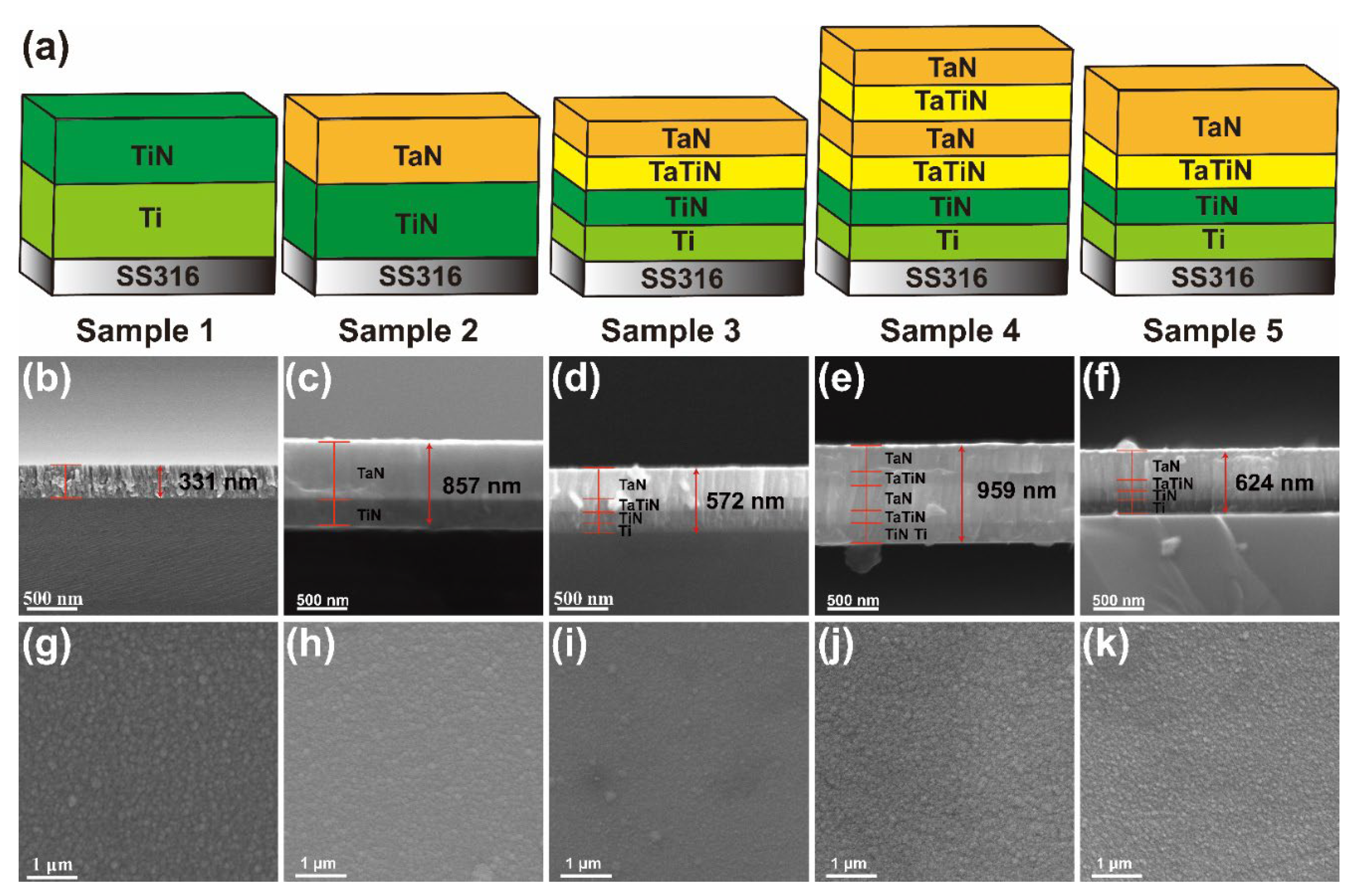
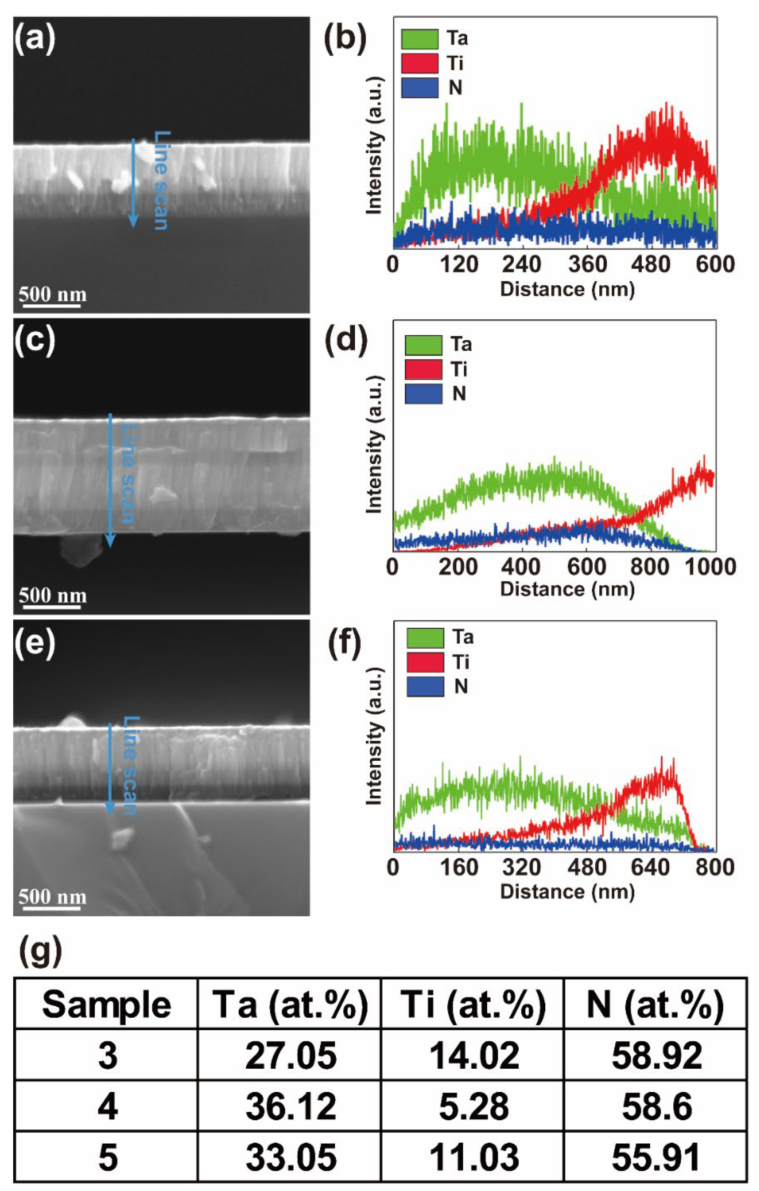
3.1. Morphology and Composition of the Coatings

To investigate the effects of the modulation period, coating thickness, transition layer on the corrosion resistance, and electrical conductivity of the coatings, we designed five different structures (Figure 1a). We first prepared the TiN/Ti and TaN/TiN coatings as the benchmark. To study the effect of the transition layer, we prepared the TaN/(Ta,Ti)N/TiN/Ti coating (Sample 3). The effects of multiple junctions (Sample 4) and layer thickness (Sample 5) were also investigated. We further characterized the morphology and thickness using scanning electron microscopy (SEM) (Figure 1b–k). The multilayer coatings well adhered to the substrate. All the coatings were continuous and intact without microcracks or vacancies in the deposited multilayer (Figure 1b–k). The coating thicknesses were 857 and 572 nm for Samples 2 and 3, respectively, which were both thinner than in previous reports [22,26,27,28,29,30,31] and satisfied the requirements of the Department of Energy (DOE) [23]. The finishing surface morphology of all samples was flat, continuous, and dense without cracks, and the columnar crystal structure of the coating was separated by the interface without continuity. Compared to conventional arc ion plating technology [32], which features detrimental microparticles scattering on the surface of the coating, our coatings showed much reduced particles, which indicated their promising mechanical behaviors [17] (Figure 1g–k).
We further analyzed the phase composition using X-ray diffraction (XRD) (Figure 2). The main characteristic diffraction peaks are located at around 35.9°, 41.7°, and 60.4°, corresponding to the (111), (200), and (220) crystal planes of the cubic B1 NaCl-type-structured TaN, respectively. This corresponds to the standard XRD data recorded in JCPDS cards (No. 89-5196, marked with an orange line in Figure 2). The diffraction peaks of α-TiN are at 36.7°, 38°, 42°, and 61.7°, corresponding to the (112), (103), (004), and (204) crystallographic planes, respectively. This corresponds to the standard XRD data recorded in JCPDS cards (No. 76-1834, marked with a purple line in Figure 2). The diffraction peaks of Ti are at 56.4°, corresponding to the (201) crystallographic plane. This corresponds to the standard XRD data recorded in JCPDS cards (No. 51-0631, marked with a dark green line in Figure 2). The lower diffraction peak intensity of TiN may be due to poor crystallinity, which is also a common phenomenon in magnetron sputtering coatings [17]. The intensity of diffraction peaks increases significantly with the increase of the outermost layer of TaN, and the thickness of the coating significantly affects the crystallinity.
We also carried out cross-sectional SEM characterizations and EDS line-scan analysis (Figure 3), which showed the composition evolution due to the change of coating structures. Specifically, Samples 3 and 5 showed TaN layers with a thickness of 200 nm and 300 nm, respectively, as the top layer. The TaTiN transition layer of about 120 nm thickness was underneath this layer. In Sample 4, the change of composition for Ta and Ti was more synchronous compared to Samples 3 and 5, which may because the highly similar crystal structures of TaN and TiN facilitate the diffusion between layers to form the solid solution at a high deposition temperature (350 °C) [33]. We also analyzed the atomic compositions for coatings (Figure 3g). The atomic percentages of Sample 3 were 27.05% Ta, 14.02% Ti, and 58.92% N. The atomic percentages of Sample 4 were 36.12% Ta, 5.28% Ti, and 58.60% N. The atomic percentages of Sample 5 were 33.05% Ta, 11.03% Ti, and 55.91% N. With the increase in TaN layer thickness and modulation period, the atomic composition of Ti decreased, which was consistent with our experimental design. The composition of metal (Ti and Ta) versus N was close to 1.

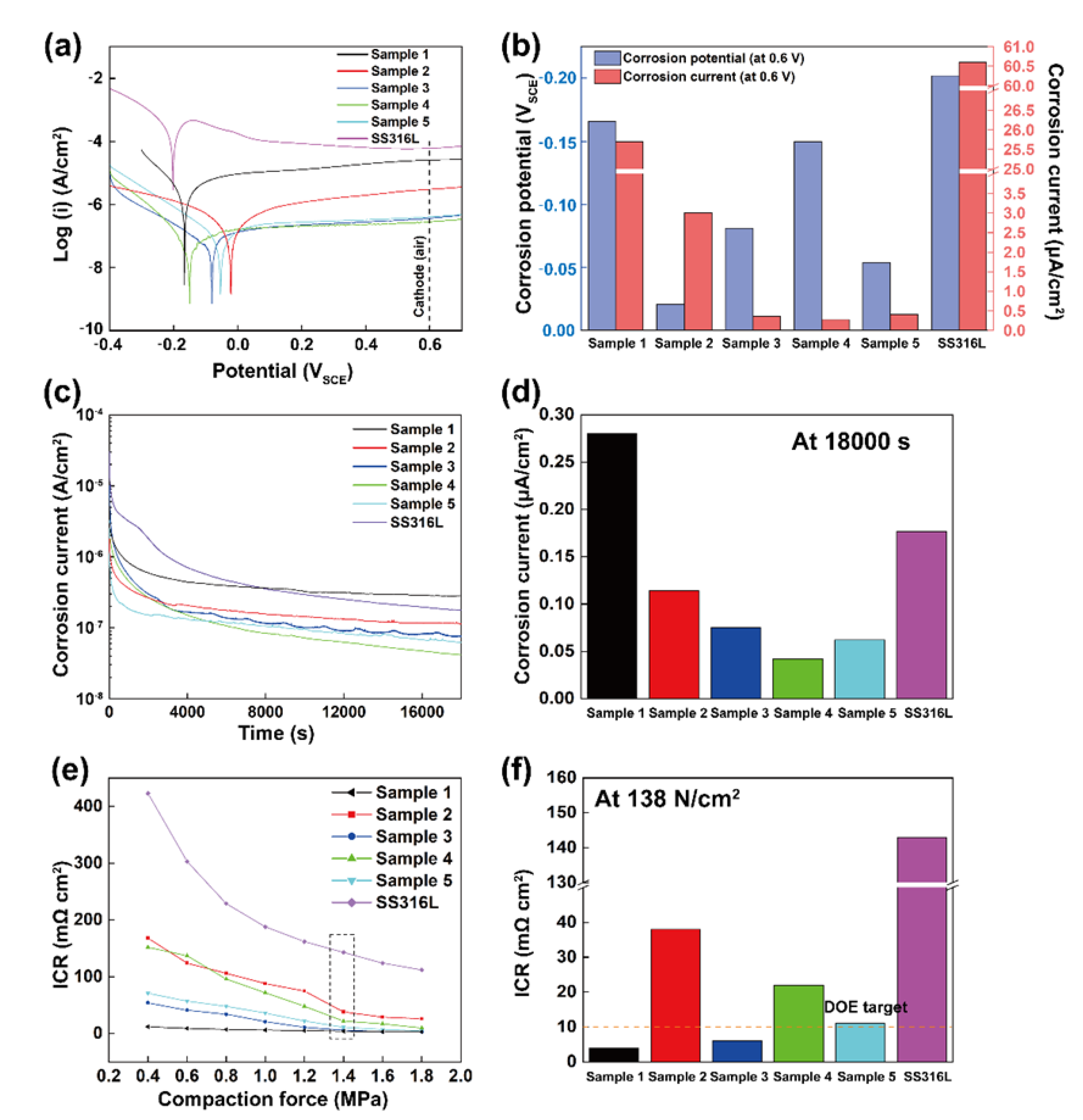
3.2. Corrosion Resistance and Interfacial Contact Resistance (ICR)

We further evaluated the corrosion resistance performance of coatings as the bipolar plate. As shown in Figure 4a, the potentiodynamic polarization method was applied to the coated sample and bare SS316L in 0.5 M H2SO4 + 2 ppm HF at 70 °C. As expected, between −0.2 and −0.1 V, the uncoated SS316L substrate has an obvious anode active dissolution area, which is due to the passivation film not being stable [13]. Nevertheless, all samples with coatings do not show the passivation behavior of the activation–passivation transition zone; the passivation reaction is rapid under the corrosive solution environment. This process from the main dynamic to the passive dynamic changes rapidly with the increase in electric potential, indicating that the coating has stronger chemical stability than the bare SS316L substrate. The corrosion potential of SS316L was −0.202 V (Figure 4a), which was lower than that of Sample 4 (−0.15 V), and much lower than those of Sample 3 (−0.082 V), Sample 5 (−0.054 V), and Sample 2 (−0.021 V). In principle, high corrosion potential suggests high chemical inertness and better corrosion resistance [34]. Therefore, Sample 2 may have the best corrosion resistance performance. Importantly, it is noteworthy that the self-corrosion potential of the coating decreased with the increasing layers within the coatings, which was due to the corrosion potential difference between Ta and Ti, leading to the generation of a corrosion galvanic couple at the interface. Therefore, when the etching solution reaches the interface through the channel formed by the columnar crystals, these vulnerable galvanic couples can be readily attacked and corroded [35].
The corrosion currents at the cathode operating potential (0.6 V vs. SCE) of Samples 1, 2, 3, 4, and 5 were 25.7, 3.01, 0.369, 0.28, and 0.408 μA/cm2, respectively (Figure 4a,b). With the increase of the layers/interfaces within the coatings, the corrosion current decreased significantly. In general, the electrolyte passes through the layers along the gap channels of the columnar crystals formed during the magnetron sputtering process, which causes corrosion and structural failures. Therefore, the multiple layered coating can effectively prevent the continuous growth of columnar crystals and block the channel towards the interface [35].
To further evaluate the stability of the TaN/(Ta,Ti)N/TiN/Ti multilayer coating deposited on SS316L in the corrosive environment of fuel cells, we also performed constant potential measurements at cathode potential (0.6 V vs. SCE) for the coated samples and the uncoated SS316L substrate. At the beginning of life stage, uncoated SS316L showed a current density of 0.177 μA/cm2, which was much higher than those of Sample 2 (0.114 μA/cm2), Sample 3 (0.075 μA/cm2), Sample 4 (0.042 μA/cm2), and Sample 5 (0.062 μA/cm2) (Figure 4c,d). Over the course of the stability test, the corrosion current gradually decreased and then stabilized after 5 h. The stability of the potentiostatic polarization curve may result from the cathode operating potential of 0.6 V being in the passivation region of the polarization curve [32]. The corrosion current density of the coated sample is much lower than that of the uncoated sample, which indicates that fewer electrochemical reactions occur at the interface between the coating and the adjacent electrolyte [30]. The amount of metal ions dissolved is less, which improves the performance of the SS316L bipolar plate. Based on this stability test, Sample 4 had the lowest corrosion current and thus showed the best corrosion resistance, which was attributed to the fact that Sample 4 had a thicker coating thickness and more interfaces than Samples 3 and 5, despite similar surface microstructures. Therefore, it is difficult for the electrolyte to diffuse through the flow channel and corrode the structure of matrix, which is also consistent with the lowest corrosion current from the potentiodynamic polarization test (Figure 4a,b). Together, increasing the thickness of coatings and layers of coatings within the coating can improve the corrosion resistance of the TaN/(Ta,Ti)N/TiN/Ti coating.
In addition to corrosion resistance performance, the overall conductivity of fuel cell stacks is critical for the efficiency of fuel cells, especially under high-current density regions [36]. In principle, the interface conductivity should be maximized to improve the largest output. As shown in Figure 4e, as the applied pressure increased, the actual contact area between the carbon paper and the sample became better; thus, the contact resistance decreased with the applied pressure [37]. The contact resistances of the coated samples at 138 N/cm2 were 4 (Sample 1), 38 (Sample 2), 6 (Sample 3), 22 (Sample 4), and 11 mΩ cm2 (Sample 5). Among them, the contact resistance of Samples 1 and 3 met the DOE 2020 target [23] of 10 mΩ cm2, and Sample 5 closely approached the DOE targets; the performance of our Sample 3 was comparable with the recently reported Tantalum series protective coating (Table S2). However, the contact resistance of SS316L is 143 mΩ cm2 at 138 N/cm2, far beyond the DOE requirement. The reasons for the improved interface conductivity may be attributed to the following: (1) TaN (30 mΩ·cm) in the outer layer has excellent electrical conductivity [26]; (2) The structure of TaN is similar to TiN, and Ta and Ti have similar atomic radii and the same coordination number, which has been leveraged to grow their epitaxial films [38]; (3) The existence of the transition layer reduces the grain boundaries at the interface, reduces the phenomenon of electron scattering, and improves the electrical conductivity [13,39]. Compared to Sample 2, Sample 3 (with the transition layer) effectively reduces the electron scattering phenomenon between the TaN layer and the TiN layer and significantly improves the overall conductivity of the coating. However, increasing the thickness of the TaN layer and the number of interfaces of the coating may lead to an increase in the resistance of the coating, which was evidenced in Samples 4 and 5.

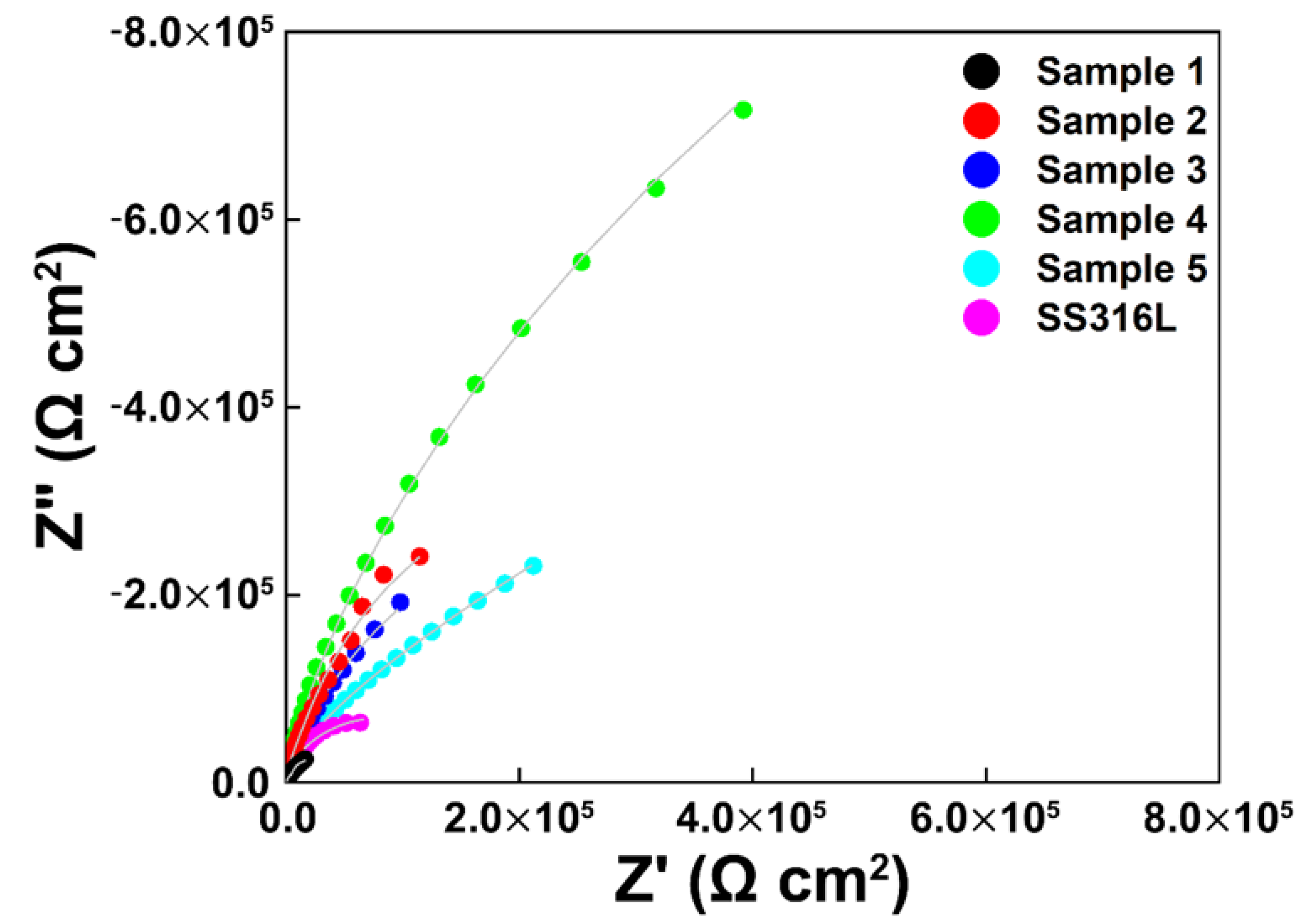
3.3. Electrochemical Impedance Spectroscopy (EIS)

The Nyquist plots and Bode-phase angle plots for the TaN/(Ta,Ti)N/TiN/Ti coatings and bare SS316L at their respective EOCP are shown in Figure 5 and Figure 6a–f, respectively. Both the coated samples and bare SS316L are an incomplete semicircle in 10−2 Hz to 105 Hz. The capacitive semicircle diameter of the coated sample was larger than that of the bare SS316L. In general, the capacitive arc diameter is an indicator of corrosion resistance. A larger diameter usually represents better corrosion resistance [40]. From the Bode plots (Figure 6a–f), the coated samples show a broader plateau around the maximum phase angle of −85°, which corresponded to the slope of the linear change between log |Z| and log f (frequency), which is almost −1 from 10−1 Hz to 103 Hz. This major feature of capacitive behavior suggested that the TaN/(Ta,Ti)N/TiN/Ti coating is an isolation layer with high resistance and low capacitance [41]. The bare SS316L substrate has a maximum phase angle of −80° and presents a narrower peak. The impedance modulus value in the low-frequency area was lower, and it decreased with the decreasing phase angle. These data indicate that the passive coating of the coated sample exhibits a more purely capacitive behavior in corrosive media compared to the bare SS316L [42].
We further utilized equivalent electrical circuits to simulate and calculate EIS data. For the bare SS316L substrate, since the Bode phase diagram from 10−2 Hz to 105 Hz presents a one-time constant process, an equivalent circuit was used (Figure 7a). In this corrosion system, Rs is the solution resistance and QP is a CPE with capacitive characteristics. Rct is passivation film resistance. In the case of coated samples, their Bode phase diagrams show asymmetrically wide peaks, which are caused by two-time constant processes corresponding to the mid–low frequency region of electrochemical behavior [43]. Therefore, an equivalent circuit diagram (as shown in Figure 7b) was adopted, where Rct represents the charge transfer resistance at the solution/coating interface and Qdl represents the double-layer capacitance associated with the passivation film. RC in the main circuit represents the resistance. QC is the capacitance of the coating. The fitting results are summarized in Figure 7c.
Rct stands for charge transfer resistance, and its value reflects the speed of the electrochemical reaction. The Rct value represents the corrosion resistance of the coating; the greater the value, the better the corrosion resistance. This is because a dense and stable passivation layer (TA-O-N) is formed on the coating, which can protect the coating from corrosive PEMFCs [22]. A lower double-layer capacitance (Qdl) was observed for the coated samples in an accelerated corrosion environment. The double-layer capacitance (Qdl) relates to the charge accumulation caused by the corrosion reaction and the thickness of the passivation film. The lower the double-layer capacitance (Qdl), the better the corrosion resistance [44]. A higher double-layer capacitance of SS316L is related to the instability of its passive film in the corrosive liquid [44]. In comparison, the passivation film of the coated sample showed stronger stability, which is also consistent with the constant potential polarization test result. Furthermore, the leakage capacitance, which deviates from the ideal capacitance, is described by the phase element and the coefficient n. When CPE is the ideal capacitance, n = 1. When CPE describes the dispersion of the time constant due to porosity, roughness, and other possible inhomogeneity, n is less than 1. The larger the value of n, the denser the structure of the coating, the fewer the defects, and the better the corrosion resistance [45]. The coated samples all had a high n value, which was attributed to the high ionization rate of the dual-target unbalanced magnetron sputtering technology, leading to a compact coating structure. The existence of the transition layer improves the compatibility between the layers and reduces the defects at the interface. The Rct of SS316L was 9.4 × 10⁴ Ω·cm2 (Figure 7c), which was lower than that of Sample 2 (4.8 × 10⁵ Ω·cm2), and much lower than those of Sample 3 (7.2 × 10⁵ Ω·cm2), Sample 4 (4.1 × 10⁶ Ω·cm2), and Sample 5 (2.9 × 10⁶ Ω·cm2). Compared with the Rct and Qdl values of the individual sample under the OCP potential environment of the accelerated corrosion solution, the coated sample has better corrosion resistance than the uncoated substrate, and Sample 4 has the best corrosion resistance (Rct = 4.1 × 10⁶ Ω·cm2), consistent with the conclusion above.
Rct values of coated samples were two orders of magnitude higher than those of uncoated SS316L in each simulated fuel cell corrosion environment. The results show that the charge transfer resistance of TaN/(Ta,Ti)N/TiN/Ti coating is much higher than that of uncoated SS316L. The TaN/(Ta,Ti)N/TiN/Ti coating significantly inhibits the chemical reaction and ion dissolution of the metal substrate, and has excellent corrosion resistance protection.

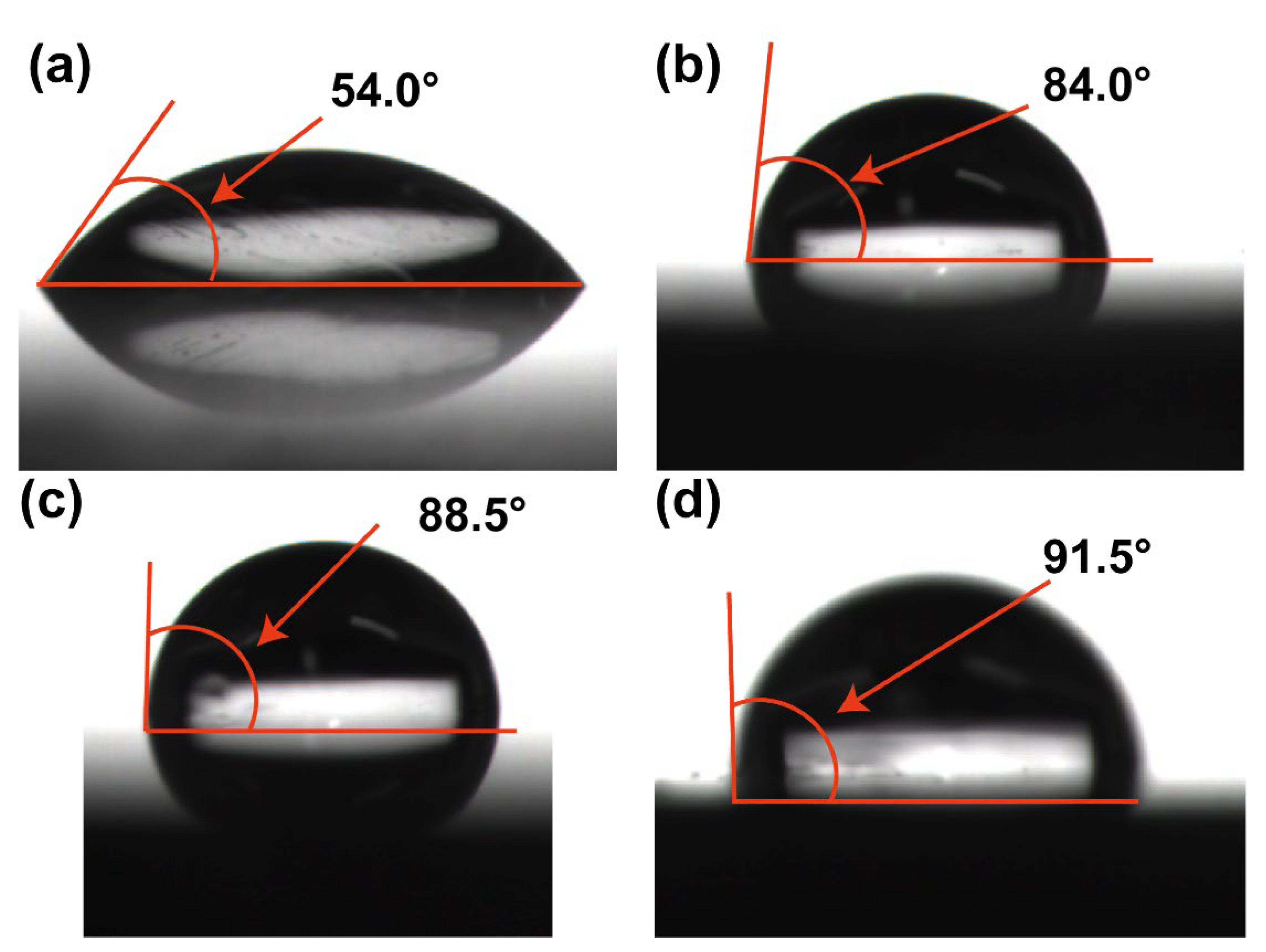
3.4. Contact Angle Measurements

As the product of a proton exchange membrane fuel cell, water can keep the membrane electrode wet [46], but excessive water will hinder the reaction gas from entering the electrode, increase the corrosion rate of the bipolar plate [47], and cause flooding in the catalyst layer. Therefore, the bipolar plate needs to be hydrophobic to prevent water flooding. As shown in Figure 8, the water contact angles of TaN/(Ta,Ti)N/TiN/Ti-coated and uncoated SS316L were measured. The water contact angles between the bare SS316L substrate and TaN/(Ta,Ti)N/TiN/Ti coating were 54.0° (SS316L), 84.0° (Sample 3), 88.5° (Sample 4), and 91.5° (Sample 5), respectively. Compared with SS316L, the water contact angle of the TaN/(Ta,Ti)N/TiN/Ti coating increases significantly, which suggests that SS316L with coating is more hydrophobic due to the non-polar nature of metal nitride surface chemistry [48]. Therefore, the TaN/(Ta,Ti)N/TiN/Ti coating improves the hydrophobicity of the SS316L bipolar plate.

4. Conclusions

In summary, we demonstrated a TaN/(Ta,Ti)N/TiN/Ti coating multilayer on SS316L by direct current unbalanced magnetron sputtering, showing much improved corrosion resistance without harming the conductivity. The corrosion current of the TaN/(Ta,Ti)N/TiN/Ti coating multilayer was only 0.369 μA·cm−2 (at +0.6 V vs. SCE) under 0.5 M H2SO4 + 2 ppm HF at 70 °C, surpassing the DOE standard. The corrosion current was only 0.075 μA·cm−2 (at +0.6 V vs. SCE) upon 5 h of electrostatic potential polarization testing. Importantly, the TaN/(Ta,Ti)N/TiN/Ti multilayer coating showed low contact resistance (6 mΩ cm2 at 138 N/cm2) and met the DOE standard simultaneously. Based on EIS and an equivalent circuit model, the oxidation reaction and dissolution of metal were largely impeded. The design of the TaN/(Ta,Ti)N/TiN/Ti coating multilayer provides a valid pathway to overcoming the dilemma between low electric resistance and high corrosion resistance.

Supplementary Materials

The following supporting information can be downloaded at: https://www.mdpi.com/article/10.3390/coatings12050689/s1, Table S1: Deposition parameters of Ta/(Ta,Ti)N/TiN/Ti multilayer coatings; Figure S1: Schematic diagram of interface contact resistance measuring fixture; Figure S2: Electrochemical performance of thin films; Table S2: Tantalum series protective coating test data reported in literature; Table S3: Comparison of graphite bipolar plate and SS316L.

Author Contributions

Conceptualization, R.T., Q.L., S.Z. and J.S.; methodology, R.M.; software, B.J.; validation, M.Y. (Mai Yang), Y.Y. and L.Z.; formal analysis, R.T. and R.M.; investigation, M.Y. (Meijun Yang); data curation, R.T.; writing—original draft preparation, R.M. and Q.L.; writing—review and editing, Q.L. All authors have read and agreed to the published version of the manuscript.

Funding

This work was supported by the Guangdong Major Project of Basic and Applied Basic Research (2021B0301030001); Key-Area Research and Development Program of Guangdong Province (2021B0707050001, 2019B121204001, and 2020B010181001); the Chaozhou Science and Technology Project (2019PT01); the Self-innovation Research Funding Project of Hanjiang Laboratory (HJL202012A001, HJL202012A002, and HJL202012A003); and the Major Science and Technology Project in Zhongshan City, Guangdong Province (2019AG029). This work was also supported by the Joint Fund of the Ministry of Education for Pre-research of Equipment (6141A02022257), the Science Challenge Project (TZ2016001), the National Natural Science Foundation of China (51861145306, 51872212, and 51972244), and the 111 Project (B13035). It was also supported by the International Science and Technology Cooperation Program of China (2018YFE0103600) and the Technological Innovation of Hubei Province, China (2019AAA030).

Institutional Review Board Statement

Not applicable.

Informed Consent Statement

Not applicable.

Data Availability Statement

Data sharing is not applicable to this article.

Conflicts of Interest

The authors declare no conflict of interest.

References

  1. Li, M.C.; Zeng, C.L.; Luo, S.Z.; Shen, J.N.; Lin, H.C.; Cao, C.N. Electrochemical Corrosion Characteristics of Type 316 Stainless Steel in Simulated Anode Environment for PEMFC. Electrochim. Acta 2003, 48, 1735–1741. [Google Scholar] [CrossRef]
  2. Lee, S.J.; Lai, J.J.; Huang, C.H. Stainless Steel Bipolar Plates. J. Power Sources 2005, 145, 362–368. [Google Scholar] [CrossRef]
  3. Cho, E.A.; Jeon, U.S.; Hong, S.A.; Oh, I.H.; Kang, S.G. Performance of a 1 KW-Class PEMFC Stack Using TiN-Coated 316 Stainless Steel Bipolar Plates. J. Power Sources 2005, 142, 177–183. [Google Scholar] [CrossRef]
  4. Kim, M.; Lim, J.W.; Lee, D.G. Electrical Contact Resistance between Anode and Cathode Bipolar Plates with Respect to Surface Conditions. Compos. Struct. 2018, 189, 79–86. [Google Scholar] [CrossRef]
  5. Hermann, A.; Chaudhuri, T.; Spagnol, P. Bipolar Plates for PEM Fuel Cells: A Review. Int. J. Hydrogen Energy 2005, 30, 1297–1302. [Google Scholar] [CrossRef]
  6. Middelman, E.; Kout, W.; Vogelaar, B.; Lenssen, J.; de Waal, E. Bipolar Plates for PEM Fuel Cells. J. Power Sources 2003, 118, 44–46. [Google Scholar] [CrossRef]
  7. Cooper, J.S. Design Analysis of PEMFC Bipolar Plates Considering Stack Manufacturing and Environment Impact. J. Power Sources 2004, 129, 152–169. [Google Scholar] [CrossRef]
  8. Akhtar, M.N.; Sulong, A.B.; Umer, A.; Yousaf, A.B.; Khan, M.A. Multi-Component MWCNT/NG/EP-Based Bipolar Plates with Enhanced Mechanical and Electrical Characteristics Fabricated by Compression Moulding. Ceram. Int. 2018, 44, 14457–14464. [Google Scholar] [CrossRef]
  9. Lin, K.; Li, X.; Dong, H.; Du, S.; Lu, Y.; Ji, X.; Gu, D. Surface Modification of 316 Stainless Steel with Platinum for the Application of Bipolar Plates in High Performance Proton Exchange Membrane Fuel Cells. Int. J. Hydrogen Energy 2017, 42, 2338–2348. [Google Scholar] [CrossRef]
  10. Paulauskas, I.E.; Brady, M.P.; Meyer, H.M.; Buchanan, R.A.; Walker, L.R. Corrosion Behavior of CrN, Cr2N and π Phase Surfaces on Nitrided Ni-50Cr for Proton Exchange Membrane Fuel Cell Bipolar Plates. Corros. Sci. 2006, 48, 3157–3171. [Google Scholar] [CrossRef]
  11. Barranco, J.; Barreras, F.; Lozano, A.; Maza, M. Influence of CrN-Coating Thickness on the Corrosion Resistance Behaviour of Aluminium-Based Bipolar Plates. J. Power Sources 2011, 196, 4283–4289. [Google Scholar] [CrossRef]
  12. Haye, E.; Deschamps, F.; Caldarella, G.; Piedboeuf, M.L.; Lafort, A.; Cornil, H.; Colomer, J.F.; Pireaux, J.J.; Job, N. Formable Chromium Nitride Coatings for Proton Exchange Membrane Fuel Cell Stainless Steel Bipolar Plates. Int. J. Hydrogen Energy 2020, 45, 15358–15365. [Google Scholar] [CrossRef]
  13. Yang, M.; Zhang, D. Effect of Surface Treatment on the Interfacial Contact Resistance and Corrosion Resistance of Fe-Ni-Cr Alloy as a Bipolar Plate for Polymer Electrolyte Membrane Fuel Cells. Energy 2014, 64, 242–247. [Google Scholar] [CrossRef]
  14. Yun, Y.H. Deposition of Gold-Titanium and Gold-Nickel Coatings on Electropolished 316L Stainless Steel Bipolar Plates for Proton Exchange Membrane Fuel Cells. Int. J. Hydrogen Energy 2010, 35, 1713–1718. [Google Scholar] [CrossRef]
  15. Kumar, A.; Ricketts, M.; Hirano, S. Ex Situ Evaluation of Nanometer Range Gold Coating on Stainless Steel Substrate for Automotive Polymer Electrolyte Membrane Fuel Cell Bipolar Plate. J. Power Sources 2010, 195, 1401–1407. [Google Scholar] [CrossRef]
  16. Asri, N.F.; Husaini, T.; Sulong, A.B.; Majlan, E.H.; Daud, W.R.W. Coating of Stainless Steel and Titanium Bipolar Plates for Anticorrosion in PEMFC: A Review. Int. J. Hydrogen Energy 2017, 42, 9135–9148. [Google Scholar] [CrossRef]
  17. Musil, J.; Baroch, P.; Vlček, J.; Nam, K.H.; Han, J.G. Reactive Magnetron Sputtering of Thin Films: Present Status and Trends. Thin Solid Films 2005, 475, 208–218. [Google Scholar] [CrossRef]
  18. Firouzabadi, S.S.; Dehghani, K.; Naderi, M.; Mahboubi, F. Numerical Investigation of Sputtering Power Effect on Nano-Tribological Properties of Tantalum-Nitride Film Using Molecular Dynamics Simulation. Appl. Surf. Sci. 2016, 367, 197–204. [Google Scholar] [CrossRef]
  19. Riekkinen, T.; Molarius, J.; Laurila, T.; Nurmela, A.; Suni, I.; Kivilahti, J.K. Reactive Sputter Deposition and Properties of Ta N Thin Films. Microelectron. Eng. 2002, 64, 289–297. [Google Scholar] [CrossRef]
  20. Bi, F.; Hou, K.; Yi, P.; Peng, L.; Lai, X. Mechanisms of Growth, Properties and Degradation of Amorphous Carbon Films by Closed Field Unbalanced Magnetron Sputtering on Stainless Steel Bipolar Plates for PEMFCs. Appl. Surf. Sci. 2017, 422, 921–931. [Google Scholar] [CrossRef]
  21. Feng, K.; Shen, Y.; Mai, J.; Liu, D.; Cai, X. An Investigation into Nickel Implanted 316L Stainless Steel as a Bipolar Plate for PEM Fuel Cell. J. Power Sources 2008, 182, 145–152. [Google Scholar] [CrossRef]
  22. Wang, L.; Li, L.; Liu, H.; Wang, S.; Fang, H.; Gao, H.; Gao, K.; Zhang, Y.; Sun, J.; Yan, J. Polylaminate TaN/Ta Coating Modified Ferritic Stainless Steel Bipolar Plate for High Temperature Proton Exchange Membrane Fuel Cell. J. Power Sources 2018, 399, 343–349. [Google Scholar] [CrossRef]
  23. U.S. Department of Energy (2017) 3.4-18; 2017. Available online: https://www.energy.gov/eere/fuelcells/doe-technical-targets-polymer-electrolyte-membrane-fuel-cell-components (accessed on 27 March 2022).
  24. Bräuer, G.; Szyszka, B.; Vergöhl, M.; Bandorf, R. Magnetron Sputtering-Milestones of 30 Years. Vacuum 2010, 84, 1354–1359. [Google Scholar] [CrossRef]
  25. Wang, H.; Sweikart, M.A.; Turner, J.A. Stainless Steel as Bipolar Plate Material for Polymer Electrolyte Membrane Fuel Cells. J. Power Sources 2003, 115, 243–251. [Google Scholar] [CrossRef]
  26. Wang, L.; Li, L.; Shen, J.; Gao, H.; Sun, J.; Wang, H.; Cao, Y. High Conductivity and Anti-Corrosive Tantalum Surface Modified Ferritic Stainless Steel Bipolar Plate for Direct Ethanol Fuel Cell. Results Phys. 2019, 14, 102394. [Google Scholar] [CrossRef]
  27. Choe, C.; Choi, H.; Hong, W.; Lee, J.J. Tantalum Nitride Coated AISI 316L as Bipolar Plate for Polymer Electrolyte Membrane Fuel Cell. Int. J. Hydrogen Energy 2012, 37, 405–411. [Google Scholar] [CrossRef]
  28. Manso, A.P.; Marzo, F.F.; Garicano, X.; Alegre, C.; Lozano, A.; Barreras, F. Corrosion Behavior of Tantalum Coatings on AISI 316L Stainless Steel Substrate for Bipolar Plates of PEM Fuel Cells. Int. J. Hydrogen Energy 2020, 45, 20679–20691. [Google Scholar] [CrossRef]
  29. Wu, B.; Fu, Y.; Xu, J.; Lin, G.; Hou, M. Chromium Nitride Films on Stainless Steel as Bipolar Plate for Proton Exchange Membrane Fuel Cell. J. Power Sources 2009, 194, 976–980. [Google Scholar] [CrossRef]
  30. Alishahi, M.; Mahboubi, F.; Mousavi Khoie, S.M.; Aparicio, M.; Hübner, R.; Soldera, F.; Gago, R. Electrochemical Behavior of Nanocrystalline Ta/TaN Multilayer on 316L Stainless Steel: Novel Bipolar Plates for Proton Exchange Membrane Fuel-Cells. J. Power Sources 2016, 322, 1–9. [Google Scholar] [CrossRef]
  31. Mendizabal, L.; Oedegaard, A.; Kongstein, O.E.; Lædre, S.; Walmsley, J.; Barriga, J.; Gonzalez, J.J. TaNX Coatings Deposited by HPPMS on SS316L Bipolar Plates for Polymer Electrolyte Membrane Fuel Cells: Correlation between Corrosion Current, Contact Resistance and Barrier Oxide Film Formation. Int. J. Hydrogen Energy 2017, 42, 3259–3270. [Google Scholar] [CrossRef]
  32. Fu, Y.; Hou, M.; Lin, G.; Hou, J.; Shao, Z.; Yi, B. Coated 316L Stainless Steel with CrxN Film as Bipolar Plate for PEMFC Prepared by Pulsed Bias Arc Ion Plating. J. Power Sources 2008, 176, 282–286. [Google Scholar] [CrossRef]
  33. Chen, G.S.; Chen, S.T.; Huang, S.C.; Lee, H.Y. Growth Mechanism of Sputter Deposited Ta and Ta ± Nthin Ælms Induced by an Underlying Titaniumlayer and Varying Nitrogen Flow Rates. Appl. Surf. Sci. 2001, 169, 353–357. [Google Scholar] [CrossRef]
  34. Zhao, Y.; Wei, L.; Yi, P.; Peng, L. Influence of Cr-C Film Composition on Electrical and Corrosion Properties of 316L Stainless Steel as Bipolar Plates for PEMFCs. Int. J. Hydrogen Energy 2016, 41, 1142–1150. [Google Scholar] [CrossRef]
  35. Jin, J.; Liu, H.; Zheng, D.; Zhu, Z. Effects of Mo Content on the Interfacial Contact Resistance and Corrosion Properties of CrN Coatings on SS316L as Bipolar Plates in Simulated PEMFCs Environment. Int. J. Hydrogen Energy 2018, 43, 10048–10060. [Google Scholar] [CrossRef]
  36. Xu, Z.; Qiu, D.; Yi, P.; Peng, L.; Lai, X. Towards Mass Applications: A Review on the Challenges and Developments in Metallic Bipolar Plates for PEMFC. Prog. Natl. Sci. Mater. Int. 2020, 30, 815–824. [Google Scholar] [CrossRef]
  37. Xu, J.; Li, Z.; Xu, S.; Munroe, P.; Xie, Z.H. A Nanocrystalline Zirconium Carbide Coating as a Functional Corrosion-Resistant Barrier for Polymer Electrolyte Membrane Fuel Cell Application. J. Power Sources 2015, 297, 359–369. [Google Scholar] [CrossRef] [Green Version]
  38. Liu, C.; Jin, N.; Li, Z.; Liu, X. First-Principles Calculations on the Electronic Structure and Bonding Nature of TaN(111)/TiN(111) Interface. J. Alloys Comp. 2017, 717, 326–332. [Google Scholar] [CrossRef]
  39. Yang, Y.; Guo, L.; Liu, H. Influence of Fluoride Ions on Corrosion Performance of 316L Stainless Steel as Bipolar Plate Material in Simulated PEMFC Anode Environments. Int. J. Hydrogen Energy 2012, 37, 1875–1883. [Google Scholar] [CrossRef]
  40. Pugal Mani, S.; Rajendran, N. Corrosion and Interfacial Contact Resistance Behavior of Electrochemically Nitrided 316L SS Bipolar Plates for Proton Exchange Membrane Fuel Cells. Energy 2017, 133, 1050–1062. [Google Scholar] [CrossRef]
  41. Li, M.; Luo, S.; Zeng, C.; Shen, J.; Lin, H.; Cao, C. Corrosion Behavior of TiN Coated Type 316 Stainless Steel in Simulated PEMFC Environments. Corros. Sci. 2004, 46, 1369–1380. [Google Scholar] [CrossRef]
  42. Balasubramanian, S.; Ramadoss, A.; Kobayashi, A.; Muthirulandi, J. Nanocomposite Ti-Si-N Coatings Deposited by Reactive Dc Magnetron Sputtering for Biomedical Applications. J. Am. Ceram. Soc. 2012, 95, 2746–2752. [Google Scholar] [CrossRef]
  43. Wang, Y.; Northwood, D.O. An Investigation of the Electrochemical Properties of PVD TiN-Coated SS410 in Simulated PEM Fuel Cell Environments. Int. J. Hydrogen Energy 2007, 32, 895–902. [Google Scholar] [CrossRef]
  44. Pugal Mani, S.; Srinivasan, A.; Rajendran, N. Effect of Nitrides on the Corrosion Behaviour of 316L SS Bipolar Plates for Proton Exchange Membrane Fuel Cell (PEMFC). Int. J. Hydrogen Energy 2015, 40, 3359–3369. [Google Scholar] [CrossRef]
  45. Er, D.; Taghavi Pourian Azar, G.; Kazmanlı, K.; Ürgen, M. The Corrosion Protection Ability of TiAlN Coatings Produced with CA-PVD under Superimposed Pulse Bias. Surf. Coat. Technol. 2018, 346, 1–8. [Google Scholar] [CrossRef]
  46. Ous, T.; Arcoumanis, C. Degradation Aspects of Water Formation and Transport in Proton Exchange Membrane Fuel Cell: A Review. J. Power Sources 2013, 240, 558–582. [Google Scholar] [CrossRef]
  47. Wang, L.; Sun, J.; Li, P.; Jing, B.; Li, S.; Wen, Z.; Ji, S. Niobized AISI 304 Stainless Steel Bipolar Plate for Proton Exchange Membrane Fuel Cell. J. Power Sources 2012, 208, 397–403. [Google Scholar] [CrossRef]
  48. Blanco, D.; Viesca, J.L.; Mallada, M.T.; Ramajo, B.; González, R.; Battez, A.H. Wettability and Corrosion of [NTf2] Anion-Based Ionic Liquids on Steel and PVD (TiN, CrN, ZrN) Coatings. Surf. Coat. Technol. 2016, 302, 13–21. [Google Scholar] [CrossRef] [Green Version]
Figure 1. Structural and compositional characterizations of coatings. (a) Design of coating structures (not to scale). Cross-sectional SEM images of (b) Sample 1, (c) Sample 2, (d) Sample 3, (e) Sample 4, and (f) Sample 5. Surface morphology SEM images of (g) Sample 1, (h) Sample 2, (i) Sample 3, (j) Sample 4, and (k) Sample 5.
Coatings 12 00689 g001
Figure 2. X-ray diffraction patterns recorded for the as-deposited TaN/(Ta,Ti)N/TiN/Ti coatings. The orange reference peak is TaN PDF#89-5196. The purple reference peak is TiN PDF#76-1934. The dark green reference peak is Ti PDF#51-0613.
Coatings 12 00689 g002
Figure 3. Cross-sectional SEM images of (a) Sample 3, (c) Sample 4, and (e) Sample 5. Energy-dispersive spectroscopy (EDS) line analysis results of (b) Sample 3, (d) Sample 4, and (f) Sample 5. (g) Atomic percentages of Samples 3, 4, and 5.
Coatings 12 00689 g003
Figure 4. Electrochemical and electrical performance of coatings. (a) Potentiodynamic polarization curves of bare SS316L and coated samples in 0.5 M H2SO4 + 2 ppm HF solution at 70 °C. (b) Self-corrosion potential and corrosion current at 0.6 V measured by potentiodynamic polarization curves. (c) Potentiostatic polarization curves of uncoated SS316L and coated samples in 0.5 M H2SO4 + 2 ppm HF solution at 70 °C (at 0.6 V vs. SCE). (d) Current magnitude at 18,000 seconds after the potentiostatic program test (at 0.6 V vs. SCE). (e) Interface contact resistance test results after 5 h of potentiostatic polarization. (f) Contact resistance at the applied pressure of 138 N/cm2.
Coatings 12 00689 g004
Figure 5. EIS measurements and analysis of coatings. Representative Nyquist plots of uncoated SS316L and coated samples at their respective EOCP in a 0.5 M H2SO4 + 2 ppm HF solution at 70 °C.
Coatings 12 00689 g005
Figure 6. EIS measurements and analysis of coatings. Bode phase angle plots of (a) SS316L, (b) Sample 1, (c) Sample 2, (d) Sample 3, (e) Sample 4, and (f) Sample 5.
Coatings 12 00689 g006
Figure 7. An equivalent circuit was used to simulate experimental EIS data of (a) RS(QPRct) and (b) RS(QCRC(QdlRct)). (c) Fitted data based on the equivalent electrical circuits.
Coatings 12 00689 g007
Figure 8. Photographs of water droplet on (a) SS316L, (b) Sample 3, (c) Sample 4, and (d) Sample 5.
Coatings 12 00689 g008
Publisher’s Note: MDPI stays neutral with regard to jurisdictional claims in published maps and institutional affiliations.

