Article

Sandwich Structure to Enhance the Mechanical and Electrochemical Performance of TaN/(Ta/Ti)/TiN Multilayer Films Prepared by Multi-Arc Ion Plating

1
State Key Laboratory of Advanced Technology for Materials Synthesis and Processing, Wuhan University of Technology, 122 Luoshi Road, Wuhan 430070, China
2
Chaozhou Branch of Chemistry and Chemical Engineering Guangdong Laboratory, Chaozhou 521000, China
3
Advanced Engineering Technology Research Institute of Zhongshan City, Wuhan University of Technology, Zhongshan 528400, China
4
Hubei Key Laboratory of Advanced Technology for Automotive Components, Wuhan University of Technology, Wuhan 430070, China
5
Hubei Key Laboratory of Roadway Bridge and Structure Engineering, Wuhan University of Technology, 122 Luoshi Road, Wuhan 430070, China
*
Author to whom correspondence should be addressed.
Coatings 2022, 12(5), 694; https://doi.org/10.3390/coatings12050694
Submission received: 17 April 2022 / Revised: 14 May 2022 / Accepted: 17 May 2022 / Published: 19 May 2022

Abstract

:
TaN/(Ta/Ti)/TiN multilayer films at various target to substrate distances (dts), composed of hexagonal TaN, (t-Ta/fcc-Ti) and fcc-TiN with a sandwich structure, were prepared via multi-arc ion plating. With increasing dts, the deposition rate of the films first increased and then decreased, and the average grain size increased from 11.9 to 13.9 nm and then decreased to 10.4 nm. The TaN/(Ta/Ti)/TiN multilayer films have a high ratio of hardness to elastic modulus (H/E*) and H3/E*2 ratios, displaying an outstanding level of both hardness and toughness compared with Ta-related films. The nano-multilayer TaTi interlayers inhibited the columnar structure and prolonged the corrosion diffusion path by increasing stable interfaces. The TaN/(Ta/Ti)/TiN multilayer film at dts = 220 mm exhibited comprehensive properties, including a high hardness of 25 GPa, strong adhesion strength of 68 N, low coefficient of friction of 0.41, low wear rate of 2.7 × 10⁻⁶ mm3(mN)−1 and great corrosion resistance in 3.5 wt% NaCl solution, showing promising application as a protective coating.

1. Introduction

Transition metal nitrides (TMN, TM: Cr, Ti, Al, Zr, Mo, etc.) prepared by physical vapor deposition (PVD) have been widely applied in the fields of cutting tools, mold processing, turbine blades, and marine corrosion resistance [1,2]. Currently, research mainly focuses on the design of multilayer structures of nitrides to improve the wear rate and corrosion resistance simultaneously [3,4,5]. Owing to the fact that wear rate is inversely proportional to hardness, as proposed by Hutchings et al. [6,7], most films aim to pursue higher hardness to improve wear resistance. The hardness of multilayer films is drastically improved by introducing stress fields on interfaces to inhibit the generation and mobility of dislocations and hinder the slip of grain boundaries [8,9]. Several enhancement mechanisms for the multilayer structure have been proposed and applied, including Koehler type [10,11] and Hall–Petch type [5,12,13,14]. Alternate deposition of the multilayer is useful to restrain typical columnar microstructures and reduce vertical voids, and multiple interfaces are beneficial to delay corrosion penetration, thus improving corrosion resistance [15,16]. However, traditional multilayer films still face challenges in some extremely harsh environments and are often seriously damaged or even flaked off due to the synergetic effect of external factors, i.e., mechanical wear, thermal shock, oxidation at high temperature, and chemical corrosion [17,18].
In order to meet these requirements, a series of tantalum nitrides, carbides, and borides as protective coatings have been granted attention due to their high melting points, outstanding mechanical properties, and great corrosion and thermal shock resistance [19,20,21,22,23]. As the first generation of PVD coatings, TiN [15,24] has been widely used as a protective coating due to its mechanical properties and corrosion resistance, and is used here to form multilayer films with TaN. Soe et al. [1] investigated the modulation period of TaN/TiN multilayer films using magnetron sputtering (MS), and proposed that hardness was improved due to the elastic anomalies and dislocation suppression caused by different dislocation energies. Nordin et al. [25] reported that TaN/TiN multilayer films with nanoscale grains prepared using MS obtained a super-hard rating at a modulation period of 11.1 nm, based on the Hall–Petch relation, showing the highest hardness and best wear resistance compared with TiN/CrN, TiN/MoN, and TiN/NbN multilayer films. As reported by Patel et al. [26], TaN/TiN isostructural and non-isostructural superlattice coatings prepared via pulsed laser deposition (PLD) exhibited hardness enhancement and great thermal stability. However, it has been pointed out in the published literature that the difference in lattice constants between the near nitride layers leads to poor adhesion of multilayer films [3,27]. Moreover, microcracks tend to expand alone in the tangential direction and cause local spalling of films due to the huge modulus difference and interlayer stress between films and substrates during the wear process [16]. The problems mentioned above limit the applications of TaN/TiN multilayer film. In addition, the comprehensive properties of TaN/TiN, including adhesion strength, wear resistance, and corrosion behavior have rarely been reported and are worth investigating.
Multi-arc ion plating (MAIP) is widely applied in manufacturing for hard coatings due to the high deposition rate and the significant ionization of working gas and metal atoms. Because of the high kinetic energy and strong surface migration ability of metal ions, films prepared using MAIP have excellent adhesive strength. Previous research has reported that the mounting position of substrates has substantial effects on the film thickness and the mechanical, tribological and anti-corrosion properties [28,29]. However, the effects of the target to substrate distance (dts) on deposition rate, microstructure, and properties of the films in MAIP have received little attention. The study of dts is meaningful to provide ideas for the design of sample placement and loading, so as to reach the best performance of the films and manufacturing efficiency in terms of production.
In this study, we introduced Ta/Ti intermediate layers between the TaN and TiN layers to establish a sandwich structure. The insertion of the softer Ta/Ti metallic interlayer is beneficial to reduce brittleness and improve the toughness of the whole film [30,31]. In addition, more interfaces and boundaries were introduced by the TaTi interlayers, where the corrosion diffusion paths from the surface to the substrate were deflected or blocked, which improved the corrosion resistance [32]. Therefore, TaN/(Ta/Ti)/TiN multilayer films were prepared using MAIP at various distances from the target to the substrate.

2. Experimental Details

2.1. Film Preparation and Characterization

The TaN/(Ta/Ti)/TiN multilayer films were prepared using a MAIP system (Guangdong HuiCheng Vacuum Technology Co., Ltd., Guangdong, China) with a high pure Ta target (99.99%, Φ124 mm × 16 mm) and a Ti target (Shenzhen Tgt Targets Co. Ltd., Shenzhen, China, 99.999%, Φ124 mm × 16 mm) on rectangular steel substrates of PCrNi1MoA and P-type single crystalline Si (100) wafers. The steel substrates, 25 mm × 10 mm × 2 mm in size, were ground with SiC abrasive paper with grits of 800, 1000, 2000, 3000, and 5000. Afterward, the steel and Si specimens were ultrasonically cleaned in acetone for 15 min to remove debris and organic contamination. The steel and Si substrates were placed pairwise on the rotating holders at distances of 180, 200, 220, and 240 mm from the target surfaces, as shown in Figure 1a,b. During the whole process, the holders were rotated at 3 rpm and the deposition temperature was kept at 450 °C, more details are shown in Table 1. The design of the sandwich structure of TaN/(Ta/Ti)/TiN multilayer films was shown in Figure 2. The Ta/Ti interlayers were prepared in between every TiN and TaN layer. In addition, the TiN, TaN and TaN/TiN film at dts = 220 mm was deposited using the same experimental conditions for comparison.
The phase composition and orientation of the films were characterized using X-ray diffraction (XRD) applying an Empyrean (PANalytical, Malvern, UK, at 40 kV, 40 mA) equipped with Cu-Kα radiation (λ = 0.154 nm) in Bragg–Brentano configuration (B-B, 30–44°) at a speed of 0.5°/min. The surface morphology of the films was observed using a SLynx (SENSOFAR, Shanghai, China) 3D surface profilometer. The cross-sectional microstructure was observed by an FEI Quanta-250 (FEI, Houston, TX, USA, at 20 kV) field emission scanning electron microscope (FESEM) and a Talos-F200S G2 (Thermofisher, Waltham, MA, USA, at 200 kV) transmission electron microscope (TEM) with an energy dispersive X-ray spectrometer (EDS, Mn-Kα, at 10 kcps). The deposition rate of the films was calculated from the thickness divided by the deposition time (Table 1).
In order to evaluate the thermodynamic state of the plasma during deposition, the following classical formula for the mean free path was used [33]:
λ = k T 2 π d 2 P
where k = 1.381 × 10⁻²³ J/K is the Boltzmann constant, T the temperature in K, P the pressure in Pa, and d the molecular diameter of gas in m.

2.2. Mechanical Tests

The hardness and elastic modulus of the TaN/(Ta/Ti)/TiN films on PCrNi1MoA alloys were investigated based on the Oliver and Pharr method with a TI980 TriboIndenter (Bruker, Billerica, MA, USA) nano-indenter with a Berkovich 142.3° diamond indenter. Each specimen was tested and averaged for six indentations at 2 mN. The loading/unloading rate was 400 μN/s.

2.3. Tribological and Adhesive Test

The tribological properties and adhesive strengths were tested with a MFT4000 (Lanzhou HuaHui instrument technology Co., Ltd., Lanzhou, China) multi-functional surface tester. Ball-on-disc dry sliding tests were conducted using a Si3N4 ball (Φ5 mm, H = 15 GPa, Ra < 0.05 μm) as the counterpart. The wear tests were carried out at a normal load of 15 N, sliding speed of 200 mm/min, reciprocating sliding distance of 8 mm, a temperature of 20 °C and a sliding time of 3600 s. The typical morphologies of wear tracks were observed using an ST400 (NANOVEA, Allentown, USA, at 1000 Hz) three-dimensional profile system and a MX6RT (Sunny Optical Technology Co., Ltd., Yuyao, China) optical microscope (OM). The cross-sectional depth curves of the wear tracks were measured using a 90° taper angle diamond indenter using an applied load of 50 mN at a displacement distance of 2000 μm and speed of 33 μm/s. The wear rate of each wear track was calculated with the following classic formula:
W = V L × F
where V is the wear volume in mm3, L the total wear length in m, and F the applied load in N. A scratch test using an MFT4000 was carried out to evaluate the adhesive strength of TaN/(Ta/Ti)/TiN films at a maximum load of 80 N, scratch speed of 40 N/min and a scratch length of 5 mm. The details of the scratch were observed by OM.

2.4. Electrochemical Corrosion Test

Potentiodynamic polarization curves were obtained to evaluate the corrosion behaviors of TaN/(Ta/Ti)/TiN films in 3.5 wt% NaCl solution using a CHI604E electrochemical workstation (Shanghai ChenHua instrument technology Co., Ltd., Shanghai, China) at 25 °C, maintained by a thermostatic waterbath. The specimens were immersed in the 3.5 wt% NaCl solution for 3 h before the tests, and the open circuit potential (OCP) was measured for 1 h to establish an equilibrium. A three-electrode system, i.e., the standard saturated calomel electrode (SCE), platinum mesh (Pt), and TaN/(Ta/Ti)/TiN films were employed as the reference, auxiliary, and working electrode respectively. The exposed area of all specimens was 1 cm2. The polarization tests were conducted in the potential range from –1 V to 1 V at a scanning rate of 2 mV/s. Each specimen was measured three times and the corroded surfaces were observed by OM.

3. Results and Discussion

3.1. Phase Composition and Microstructure

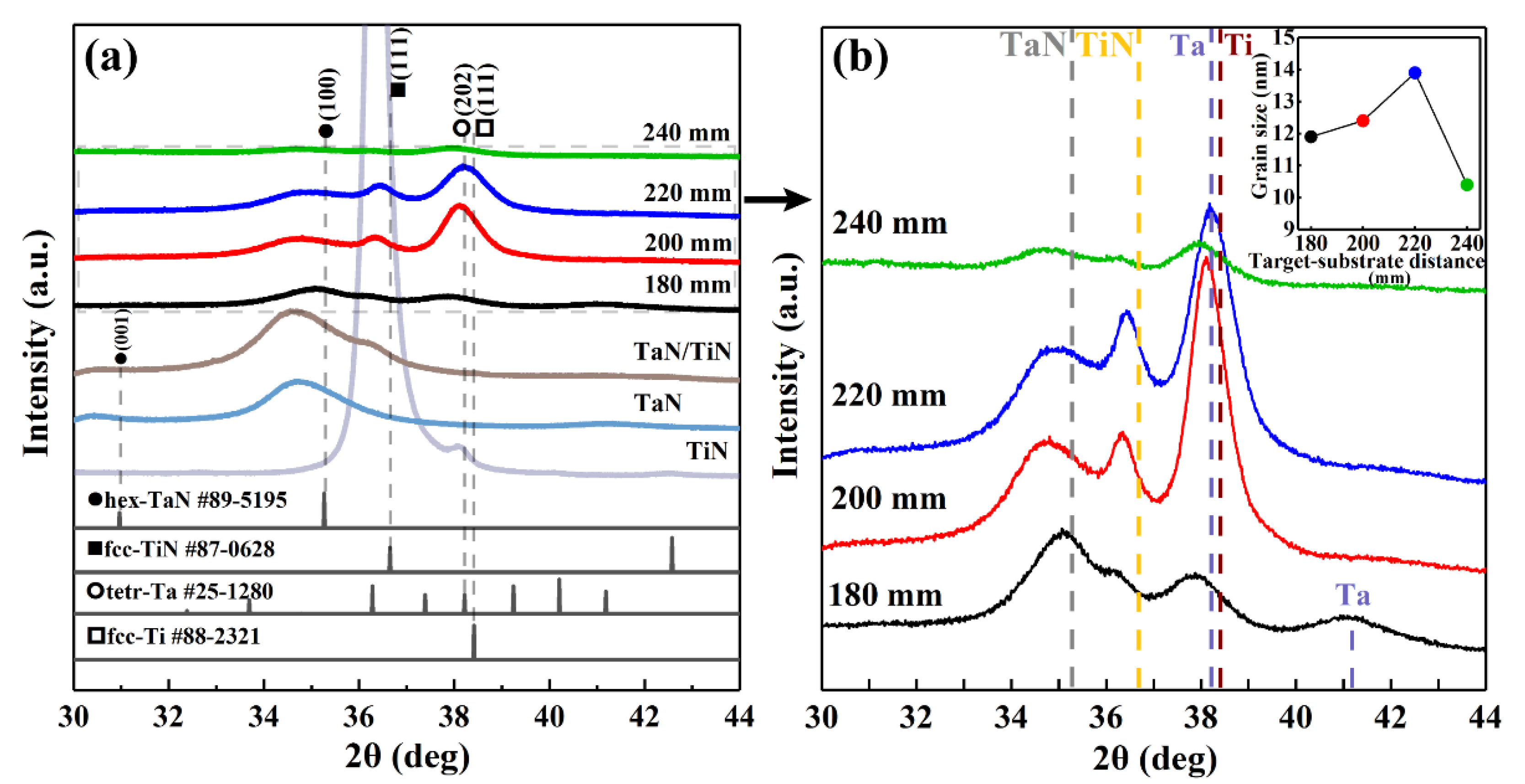
Figure 3 shows the XRD patterns of the TaN/(Ta/Ti)/TiN multilayer films, as well as those of reference specimens, including TiN, TaN, and TaN/TiN films. As displayed in Figure 3a, hexagonal TaN and face-centered cubic TiN were identified. The peak near 2θ = 34.7° was indexed to the (100) peak of the hex-TaN (No. 89-5195) and the peak near 2θ = 36.3° corresponded to the (111) peak of the fcc-TiN (No. 87-0628). In addition, the peak near 2θ = 38.0° was detected after inserting interlayers into the TaN/TiN multilayer film, indicating it probably came from the Ta/Ti layers. With the increase in dts, the crystallinity of the film first increased and then decreased, and a higher crystallinity at dts = 200 and 220 mm was found. The broadening of the peaks was mainly attributed to the increase in the lattice defects and the decrease in the grain size [34].
A significant displacement to a lower diffraction angle caused by lattice distortion was observed at various dts, indicating the existence of residual stress [35,36], as shown in Figure 3b. With an increasing dts, the peaks of TaN and TiN showed different offset angles, which indicated a complex distribution of residual stress. The average grain size of TaN, calculated using the Scherrer formula from the peak near 2θ = 34.7°, was about 4 nm with no obvious difference when dts increased, while that of TiN, calculated from the peak near 2θ = 36.3°, increased from 11.9 to 12.4 and 13.9, and then decreased to 10.4 nm at dts = 240 mm. Based on the measurement setup, the lattice planes parallel to the coating–substrate–interface were involved in the calculation. According to Formula (1), the mean free paths of Ar and N2 were 9.7 and 8.5 mm under the conditions in this work, respectively, which were less than the interval of dts for each specimen (20 mm). With the increase in dts, the metal ions collided with gas particles at a higher frequency, resulting in more energy loss. Therefore, the kinetic energy of the metal ions decreased gradually when dts increased, which is consistent with a previous report [29]. The prevention of the migration of grain boundaries introduced by enhanced ion bombardment helped to form small grains at dts = 180 mm. In addition, particles with a lower kinetic energy have poor bonding and easily fall off from the film surface at dts = 240 mm. The increasing number of nucleation sites introduced by the defects may be the reason for the decrease in grain size [37].
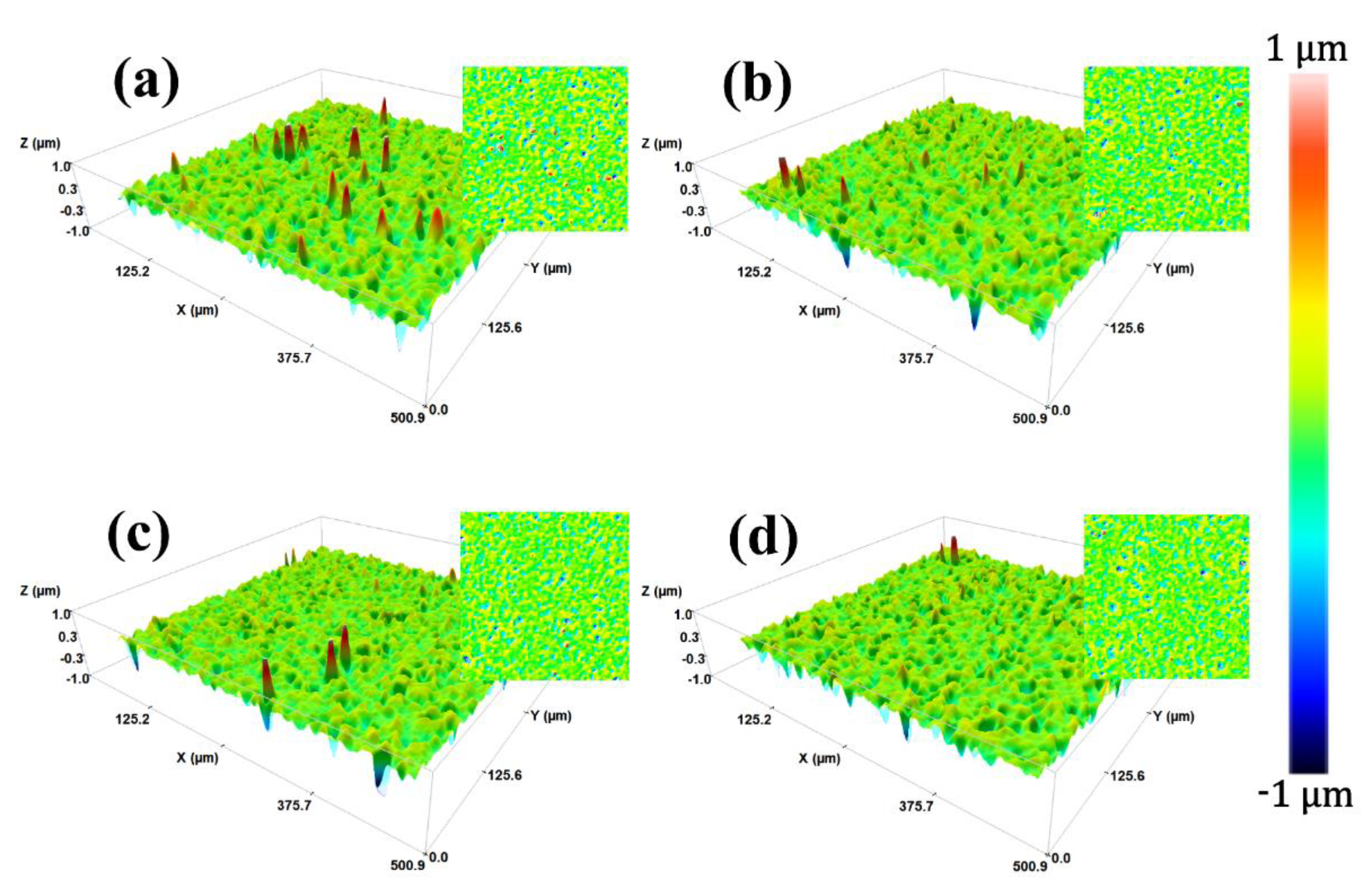
Figure 4 shows the 2D and corresponding 3D surface morphology images of TaN/(Ta/Ti)/TiN films. It was found that a number of large droplets and pits appeared on the film surface at various distances. The number of large droplets gradually decreased with the increase in the dts from 180 to 240 mm. It is well known that the droplets emitted by AIP are subjected to gravity during flying and decrease in energy as they collide with other particles. Thus, droplets at the nearest distance of 180 mm with greater kinetic energy were attached firmly to the surface of the substrate, compared with the droplets with less energy at 240 mm, which showed difficulty in adhering and fell off, forming pits. The total number of particles and pits on the film surface was almost the same when dts = 200 and 220 mm.
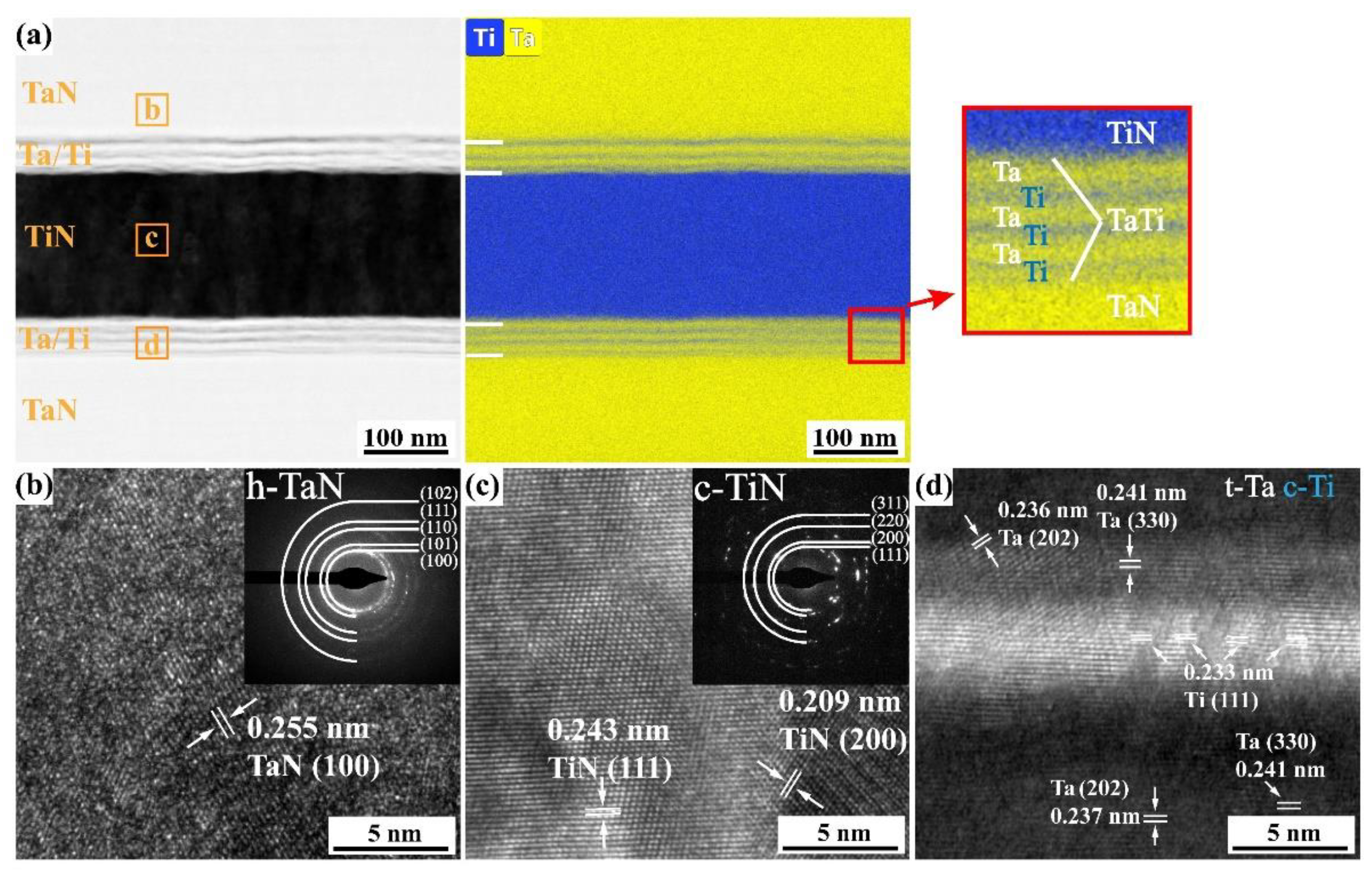
The cross-sectional SEM images of TaN/(Ta/Ti)/TiN films at various distances are shown in Figure 5a–d. The thickness of the films at dts = 180, 200, 220, and 240 mm were 1.21, 1.41, 1.50 and 0.84 μm, respectively. The deposition rate first increased and then decreased with a dts from 180 to 240 mm. Recent research has shown the electric field force from the negative bias on the substrates accelerates ions only in the sheath, close to the surface [38], which is significantly smaller than dts. Therefore, the film with a maximum dts = 240 mm had the lowest deposition rate of 22.7 nm/min. However, the thickness of the film with a smaller dts was reduced under stronger ion bombardment. The TaN/(Ta/Ti)/TiN film reached the maximum deposition rate at 40.5 nm/min when dts = 220 mm. The columnar microstructure of the TiN layer is restrained by the Ta/Ti interlayer as shown in the inset of Figure 5c, which reduced the voids between columnar crystals. The cross-sectional TEM image of TaN/(Ta/Ti)/TiN film at dts = 220 mm is shown in Figure 5e. Composed of TaN, Ta/Ti, and TiN layers, the sandwich structure with sharp interfaces is exactly the same as the design in Figure 2. The thickness of the monolayer TaN or TiN was about 200 nm. A nano-multilayer structure of Ta/Ti interlayers was about 50 nm.
As shown in Figure 6a, the interlayer Ta/Ti with the nano-multilayer structure is composed of six-layered metallic Ta and Ti, corresponding to an alternate deposition of three times for each target within 1 min due to the rotation rate of 3 rpm. The thickness of single layer Ta and Ti is about 10 and 5 nm, respectively. The fringe spacing was measured to be ~0.255 nm and the corresponding selected area electron diffractions (SAED) displayed sharp rings, where the (100), (101), etc., planes of hex-TaN are identified in Figure 6b, and fcc-TiN is identified in Figure 6c, corroborating the XRD results above. The tetragonal Ta (β-Ta), which easily forms at a low thickness [20], and the fcc-Ti are identified in the Ta/Ti layer in the HRTEM images in Figure 6d.

3.2. Mechanical Properties

As shown in the loading/unloading curves in Figure 7a, all the maximum depths of indentations are 60~65 nm, less than 1/10 the thickness of the films, to eliminate the substrate effects. Figure 7b reveals that the elastic recovery ratio ranges from 56% to 72%, calculated by WR/WI × 100%, and the multilayer structure leads to a higher recovery ratio, which is consistent with previous research [4]. The high recovery ratio of TaN/(Ta/Ti)/TiN films indicates that most of the total energy can be released in the form of elastic recovery after impact deformation from experiencing a strong external force, implying that the TaN/(Ta/Ti)/TiN films have strong impact resistance. The plastic deformation and a small part of elastic deformation energy are irreversibly stored in the material. The nanohardness (H) and elastic modulus (E) of TaN/(Ta/Ti)/TiN at various dts values are given in Figure 7c. The hardness of the films varied from 25 to 30 GPa, while the elastic modulus varied from 230 to 280 GPa, indicating a great improvement in hardness compared to the substrate (PCrNi1MoA steel, H = 3 GPa, E = 220 GPa). By increasing dts from 180 to 220 mm, the hardness decreased gradually and then increased at dts = 240 mm, while the elastic modulus showed a nearly opposite trend. The trend of hardness is attributed to the change in grain size, and is almost the opposite of that of the grain size. With the decrease of grain size, the number of grain boundaries increased, which improved the resistance of the dislocation movement, thus improving the hardness [3]. The hardness of TaN/(Ta/Ti)/TiN films is similar to that of ultra-thin nano-multilayer TaN/TiN film, reported previously [25]. The highest hardness and lowest elastic modulus are found at dts = 180 mm. Figure 7d shows the H/E* and H3/E*2 (effective modulus, E* = E/(1 − ν2), where ν is the Poisson’s ratio), which has been applied to evaluate the resistance against elastic strain to failure and plastic deformation [39], respectively. H/E* and H3/E* are usually applied to predict the toughness and friction performance of films [40]. The evaluation of H/E* and H3/E*2 is consistent with the trend for H.
To assess the mechanical performance of TaN/(Ta/Ti)/TiN multilayer films, H3/E*2 as a function of H/E* is plotted in Figure 8. The H/E* and H3/E*2 of TaC are higher than TaN, and much higher than Ta. In the literature [7,20,40,41,42,43,44,45,46,47,48,49], many elements were incorporated into TiN films to form TaMeN (Me: Zr, W, B, Al, MoAl, etc.) films, resulting in an improvement of H/E* and H3/E*2. The H/E* and H3/E*2 of TaN/(Ta/Ti)/TiN multilayer films in this work ranked at an outstanding level, indicating that the hardness and toughness were simultaneously improved.

3.3. Tribological and Adhesive Properties

Figure 9 shows the COF and acoustic signal as a function of the applied load at various dts. LC2 is the critical load of the cohesive fracture of internal films, while LC3 is the spalling failure of the films. During the scratch tests, there was no obvious local peeling of films with the acoustic signal during scratching for all the specimens due to the high ductility. The COF kept constant in the range of 12~20 N, and then increased slowly until reaching 0.6, which was exactly the COF of the substrate, and finally became stable at the maximum load. The slope change of the COF clearly reflects the critical position of the scratch test. LC2 of TaN/(Ta/Ti)/TiN films at various dts was between 20 to 25 N with no significant difference. The LC3 of TaN/(Ta/Ti)/TiN films at dts = 180, 200, 220, and 240 mm are 49, 69, 68, and 59 N, respectively, indicating great improvement in adhesive strength compared to 37 N of TaN/TiN deposited at dts = 220 mm. With increasing dts, the adhesive strength increased from 49 to 69 N, and decreased from 68 to 59 N. Previous work reported that the adhesive strength is mainly affected by the residual stresses in the film 3. The TaN and TiN layers of the TaN/(Ta/Ti)/TiN film at dts = 180 and 240 mm were subjected to different residual stresses, and the microcracks were more likely to generate and expand in the stress field between the nitride layers, leading to a lower adhesive strength. In contrast, different nitride layers in the films at 200 and 220 mm have almost the same residual stresses, which improves the homogeneity of the films and leads to stronger bonding. As the details of LC2 show, small spallation zones with local shedding of the TaN/(Ta/Ti)/TiN films occurred, similar to the results of previous research [48].
The tribological behavior, i.e., coefficient of friction (COF), wear rate, and cross-sectional profile of the wear track of the PCrNi1MoA alloy, TaN/TiN film, and TaN/(Ta/Ti)/TiN films at various dts are presented in Figure 10. The substrate exhibits a maximum COF of 0.60, a maximum wear depth of 5.2 μm and the maximum wear rate of 6.17 × 10⁻⁵ mm3(mN)−1. After being coated with the TaN/(Ta/Ti)/TiN films, the COF declined to 0.41~0.494, and the wear depth varied from 1.0~1.6 μm with the wear rate of 2.8 × 10⁻⁶~7.0 × 10⁻⁶ mm3(mN)−1, indicating the improvement in wear resistance, as displayed in Figure 10a,b. The COF of the substrate remains constant with the wear process, while that of the films gradually decreased. With increasing dts, the COF and wear rate first decreased and then increased, and the best wear resistance was obtained at dts = 220 mm. However, the tribological properties of films are independent of H, H/E* and H3/E*2 ratio, especially in systems with more than two monolayers, consistent with previous reports 35. As shown in Figure 10c,d, the effect of Ta/Ti interlayers on tribological properties is discussed. After the insertion of Ta/Ti layers, the COF, wear rate and wear depth are obviously reduced, indicating a significant improvement in wear resistance. This may be attributed to the enhancement of the overall toughness of the films by the metallic Ta/Ti interlayers [30,31].
Figure 11a–d displays the three-dimensional topography and the FESEM images of the local areas of the TaN/(Ta/Ti)/TiN films. Partial flake-off was observed on the specimen at dts = 180 mm and the friction depth exceeded the overall thickness of the film and contacted with the substrate, which was further proved by the spectrum of EDS analysis. According to Ref. [49], the lower COF of TaN/(Ta/Ti)/TiN is also related to the shearing effect of the density-arranged hex-TaN phase. The hexagonal-layered structure is prone to slip along the crystal plane under low shear stress and helps to reduce the COF. In addition, widely distributed attachments were found on the wear tracks, which were TiOx and self-lubricating TaOx, formed during the wear process in air, as reported previously [7,49]. The EDS illustrations further confirm the formation of oxidation. However, it has to be noted that there were errors in assessing the chemical composition of heavy (Ti, Ta) and light elements (C, N, O). The oxidation products can be only qualitatively determined. As shown in Figure 11e,f, a local exposure of substrate at dts = 200 mm was observed in the SEM-EDS mappings, whereas no exposure was identified at 220 mm. This result is consistent with the preceding wear depth test.

3.4. Corrosion Behavior

The corrosion behavior of TaN/(Ta/Ti)/TiN multilayer films in 3.5 wt% NaCl solution was explored through electrochemical tests, which can further evaluate the number and status of large particles and pits on the film surfaces.
The potentiodynamic polarization curves with optical photos of the corrosion morphology are shown in Figure 12a. The corrosion damage appears as broken glass-like pits at dts = 200, 220 and 240 mm, while those of the substrate and TaN/TiN film appear as a large area of corrosion pits. The film at dts = 180 mm shows serrated fluctuations when the voltage exceeds 0.2 V, attributing to that a large number of corrosion pits developing into great areas of local corrosion gradually, accompanied by persistent passivation. The critical parameters including self-corrosion potential (Ecorr) and corrosion current density (Icorr), as presented in Figure 12b, denote corrosion thermodynamic tendency and corrosion dynamic rate 7, respectively. The Ecorr and Icorr of the substrate are −0.2296 V and 3.121×10⁻⁷ A/cm2, respectively. The Ecorr of the TaN/(Ta/Ti)/TiN film at dts = 220 mm (−0.2088 V) is higher than that of the substrate, while the Ecorr of others is lower. The Icorr of TaN/(Ta/Ti)/TiN films at dts = 180, 200, 220, and 240 are 0.9811, 1.284, 1.233, and 1.509×10⁻⁷ A/cm2, respectively, suggesting distinct enhancement of corrosion resistance after coating. With the increase in dts, the Ecorr first increased and then decreased, while Icorr showed the opposite trend, and the film at dts = 220 mm showed the best corrosion resistance including the highest Ecorr and a 69% reduction of Icorr compared to the substrate. This is attributed to the TaN/(Ta/Ti)/TiN film at middle dts having fewer surface defects, i.e., adsorbed large droplets and pits introduced by shedding of droplets, consistent with the analysis in Figure 4, thus providing fewer invasion sites for the corrosive solution.
As shown in Figure 12c, the nano-multilayer structure of Ta/Ti interlayers provides more interfaces perpendicular to the growth direction for passivation, prolonging the diffusion path of the corrosion medium and thus improving corrosion resistance [32]. Therefore, the corrosion resistance of the film is significantly improved by the insertion of Ta/Ti interlayers, compared with the TaN/TiN film prepared at dts = 220 mm. The prevention of longitudinal corrosion penetration parallel to the growth direction introduced by the restraint to the columnar microstructure also improves the corrosion resistance [50].
As shown in Figure 12d, it is worth mentioning that the unavoidable large Ta droplets during the deposition of the bottom layer led to the abnormal growth of the upper layers. The abnormal growth of the bulge increased the area exposed to the corrosive solution, resulting in easier damage by the corrosive medium along with defects in the bulge. However, the design of the multilayer structure avoids the further deterioration of the abnormal growth of the TiN layer, and the bulge gradually disappears with the deposition of the multilayer, minimizing adverse effect and improving corrosion resistance.

4. Conclusions

TaN/(Ta/Ti)/TiN multilayer films enhanced by a sandwich structure were prepared at various target-to-substrate distance (dts) using multi-arc ion plating. Composed of hex-TaN and fcc-TiN, the crystallinity and grain size of the films first increased and then decreased with the increasing dts. The TaN/(Ta/Ti)/TiN multilayer films have a high hardness of 25~30 GPa, and the H, H/E* and H3/E*2 decreased first and then increased, controlled mainly by the grain size. The adhesive strength of the films increased firstly and then decreased due to the influence of the residual stresses, and the film at dts = 200 and 220 mm had higher bonding forces of 69 and 68 N, respectively. The wear behavior of the TaN/(Ta/Ti)/TiN multilayer was abrasive wear, accompanied by oxidation, and the film at dts = 220 mm had the lowest COF (0.41) and wear rate (2.7 × 10⁻⁶ mm3(mN)−1). Depending on the surface defects, the corrosion resistance of the films increased first and then decreased. The highest Ecorr of −0.2088 V and the lowest of Icorr of 0.9811 × 10⁻⁷ A/cm2 of the TaN/(Ta/Ti)/TiN multilayer film at dts = 220 mm suggested the best corrosion resistance. After the insertion of Ta/Ti interlayers, the adhesive strength was significantly improved due to the enhancement in film toughness, compared to the TaN/TiN film (37 N). In addition, the prolonging of the corrosion path by the nano-multilayer Ta/Ti improved the corrosion resistance of the TaN/(Ta/Ti)/TiN multilayer films.

Author Contributions

Conceptualization, R.T. and S.Z.; methodology, R.M. and M.Y. (Mai Yang); software, B.J.; validation, M.Y. (Mai Yang) and Y.Y.; formal analysis, R.T. and M.Y. (Mai Yang); investigation, M.Y. (Meijun Yang); data curation, R.T. and M.Y. (Mai Yang); writing—original draft preparation, M.Y. (Mai Yang) and Q.L.; writing—review and editing, Q.L. All authors have read and agreed to the published version of the manuscript.

Funding

This work was supported by the Guangdong Major Project of Basic and Applied Basic Research (2021B0301030001); Key-Area Research and Development Program of Guangdong Province (2021B0707050001, 2019B121204001, and 2020B010181001); the Chaozhou Science and Technology Project (2019PT01); the Self-innovation Research Funding Project of Hanjiang Laboratory (HJL202012A001, HJL202012A002, and HJL202012A003); and the Major Science and Technology Project in Zhongshan City, Guangdong Province (2019AG029). This work was also supported by the Joint Fund of the Ministry of Education for Pre-research of Equipment (6141A02022257), the Science Challenge Project (TZ2016001), the National Natural Science Foundation of China (51861145306, 51872212, and 51972244), and the 111 Project (B13035). It was also supported by the International Science and Technology Cooperation Program of China (2018YFE0103600) and the Technological Innovation of Hubei Province, China (2019AAA030).

Institutional Review Board Statement

Not applicable.

Informed Consent Statement

Not applicable.

Data Availability Statement

Data sharing is not applicable to this article.

Conflicts of Interest

The authors declare no conflict of interest.

References

  1. Soe, W.H.; Yamamoto, R. Mechanical Properties of Ceramic Multilayers: TiN/CrN, TiN/ZrN, and TiN/TaN. Mater. Phys. 1997, 50, 176–181. [Google Scholar] [CrossRef]
  2. Zhang, R.F.; Sheng, S.H.; Veprek, S. Stability of Ti–B–N solid solutions and the formation of nc-TiN/a-BN nanocomposites studied by combined ab initio and thermodynamic calculations. Acta Mater. 2008, 56, 4440–4449. [Google Scholar] [CrossRef]
  3. Xu, X.; Su, F.H.; Li, Z.J. Tribological properties of nanostructured TiAlN/W2N multilayer coating produced by PVD. Wear 2019, 430–431, 67–75. [Google Scholar] [CrossRef]
  4. Bobzin, K.; Brögelmann, T.; Kruppe, N.C.; Arghavani, M.; Mayer, J.; Weirich, T.E. Plastic Deformation Behavior of Nanostructured CrN/AlN Multilayer Coatings Deposited by Hybrid dcMS/HPPMS. Surf. Coat. Technol. 2017, 332, 253–261. [Google Scholar] [CrossRef]
  5. Azizpour, A.; Rainer, H.; Klimashin, F.F.; Wojcik, T.; Poursaeidi, E.; Mayrhofer, P.H. Deformation and Cracking Mechanism in CrN/TiN Multilayer Coatings. Coatings 2019, 9, 363. [Google Scholar] [CrossRef] [Green Version]
  6. Bressan, J.D.; Daros, D.P.; Sokolowski, A.; Mesquita, R.A.; Barbosa, C.A. Influence of Hardness on the wear resistance of 17-4 PH stainless steel evaluated by the pin-on-disc testing. J. Mater. Process. Technol. 2008, 205, 353–359. [Google Scholar] [CrossRef]
  7. Ren, P.; Mao, W.; Zhang, K.; Du, S.X.; Zhang, Y.D.; Chen, J.H.; Zheng, W.T. Self-Assembly of TaC@Ta Core-Shell-Like Nanocomposite Film via Solid-State Dewetting: Toward Superior Wear and Corrosion Resistance. Acta Mater. 2018, 160, 72–84. [Google Scholar] [CrossRef]
  8. Helmersson, U.; Todorova, S.; Barnett, S.A. Growth of single-crystal TiN/VN strained-layer superlattices with extremelyhigh mechanical hardness. Appl. Phys. 1987, 62, 481–484. [Google Scholar] [CrossRef]
  9. Koehler, J.S. The production of large tensile stresses by dislocations. Phys. Rev. B 1970, 2, 547–551. [Google Scholar] [CrossRef]
  10. Shinn, M.; Hultman, L.; Barnett, S.A. Growth structure and microhardness of epitaxial TiN/NbN superlattices. J. Mater. Res. 1992, 7, 901–911. [Google Scholar] [CrossRef]
  11. Madan, A.; Chu, X.; Barnett, S.A. Reactive unbalanced magnetron sputter deposition of polycrystalline TiN/NbN superlattice coatings. Surf. Coat. Technol. 1993, 57, 13–18. [Google Scholar] [CrossRef]
  12. Veprek, S.; Nesladek, P.; Niederhofer, A.; Mannling, H.; Jilek, M. Superhard nanocrystalline composites: Present status of the research and possible industrial applications. J. Vac. Sci. Technol. A 1999, 17, 2401–2420. [Google Scholar]
  13. Li, Y.; Ye, Q.W.; Zhu, Y.J.; Zhang, L.; He, Y.Y.; Zhang, S.Z.; Xiu, J.J. Microstructure, adhesion and tribological properties of CrN/CrTiAlSiN/WCrTiAlN multilayer coatings deposited on nitrocarburized AISI 4140 steel. Surf. Coat. Technol. 2019, 362, 27–34. [Google Scholar] [CrossRef]
  14. Illana, A.; Almandoz, E.; Fuentes, G.G.; Perez, F.J.; Mato, S. Comparative study of CrAlSiN monolayer and CrN/AlSiN superlattice multilayer coatings: Behavior at high temperature in steam atmosphere. J. Alloys Compd. 2019, 778, 652–661. [Google Scholar] [CrossRef]
  15. Vega, J.; Scheerer, H.; Andersohn, G.; Oechsner, M. Experimental studies of the effect of Ti interlayers on the corrosion resistance of TiN PVD coatings by using electrochemical methods. Corros. Sci. 2018, 133, 240–250. [Google Scholar] [CrossRef]
  16. Bi, F.F.; Hou, K.; Yi, P.Y.; Peng, L.F.; Lai, X.M. Mechanisms of growth, properties and degradation of amorphous carbon films by closed field unbalanced magnetron sputtering on stainless steel bipolar plates for PEMFCs. Appl. Surf. Sci. 2017, 422, 921–931. [Google Scholar] [CrossRef]
  17. Sopok, S.; Rickard, C.; Dunn, S. Thermal-chemical-mechanical gun bore erosion of an advanced artillery system part one: Theories and mechanisms. Wear 2005, 258, 671–683. [Google Scholar] [CrossRef]
  18. Mulligan, C.P.; Smith, S.B.; Vigilante, G.N. Characterization and Comparison of Magnetron Sputtered and Electroplated Gun Bore Coatings. J. Press. Vessel. Technol. 2006, 128, 240–245. [Google Scholar] [CrossRef]
  19. Lee, S.L.; Windover, D.; Audino, M.; Matson, D.W.; McClanahan, E.D. High-rate sputter deposited tantalum coating on steel for wear and erosion mitigation. Surf. Coat. Technol. 2002, 149, 62–69. [Google Scholar] [CrossRef]
  20. Myers, S.; Lin, J.L.; Souza, R.M.; Sproul, W.D.; Moore, J.J. The β to α phase transition of tantalum coatings deposited by modulated pulsed power magnetron sputtering. Surf. Coat. Technol. 2013, 214, 38–45. [Google Scholar] [CrossRef]
  21. Wang, B.Z.; Li, D.X.; Yang, Z.H. Microstructural evolution and mechanical properties of in situ nano Ta4HfC5 reinforced SiBCN composite ceramics. J. Adv. Ceram. 2020, 9, 739–748. [Google Scholar] [CrossRef]
  22. Yu, Z.J.; Yang, Y.J.; Mao, K.W. Single-source-precursor synthesis and phase evolution of SiC-TaC-C ceramic nanocomposites containing core-shell structured TaC@C nanoparticles. J. Adv. Ceram. 2020, 9, 320–328. [Google Scholar] [CrossRef]
  23. Ren, X.R.; Lv, J.S.; Li, W. Influence of MoSi2 on oxidation protective ability of TaB2-SiC coating in oxygen-containing environments within a broad temperature range. J. Adv. Ceram. 2020, 9, 703–715. [Google Scholar] [CrossRef]
  24. Chang, C.L.; Shih, S.G.; Chen, P.H. Effect of duty cycles on the deposition and characteristics of high power impulse magnetron sputtering deposited TiN thin films. Surf. Coat. Technol. 2014, 259, 232–237. [Google Scholar] [CrossRef]
  25. Nordin, M.; Larsson, M.; Hogmark, S. Mechanical and tribological properties of multilayered PVD TiN/CrN, TiN/MoN, TiN/NbN and TiN/TaN coatings on cemented carbide. Surf. Coat. Technol. 1998, 106, 234–241. [Google Scholar] [CrossRef]
  26. Patel, N.; Wang, S.L.; Inspektor, A.; Salvador, P.A. Secondary hardness enhancement in large period TiN/TaN superlattices. Surf. Coat. Technol. 2014, 254, 21–27. [Google Scholar] [CrossRef]
  27. Chang, C.L.; Chiou, T.H.; Chen, P.H. Characteristics of TiN/W2N multilayers prepared using magnetron sputter deposition with dc and pulsed dc powers. Surf. Coat. Technol. 2016, 303, 25–31. [Google Scholar] [CrossRef]
  28. Čekada, M.; Panjan, P.; Drnovšek, A.; Drobnič, M. Increase of coating thickness on sharp edges, deposited by cathodic arc evaporation. Surf. Coat. Technol. 2021, 405, 126691. [Google Scholar] [CrossRef]
  29. Ma, Y.H.; Yang, J.G.; Tian, X.B.; Gong, C.G.; Zheng, W.J.; He, Y.M.; Li, H.X.; Gao, Z.L.; Zhang, K.X.; Wei, L.F. Enhanced discharge and surface properties of TiSiCN coatings deposited by pulse-enhanced vacuum arc evaporation. Surf. Coat. Technol. 2020, 403, 126413. [Google Scholar] [CrossRef]
  30. Cai, X.J.; Gao, Y.; Cai, F.; Zhang, L.; Zhang, S.H. Effects of multi-layer structure on microstructure, wear and erosion performance of the Cr/CrN films on Ti alloy substrate. Appl. Surf. Sci. 2019, 483, 661–669. [Google Scholar] [CrossRef]
  31. Cai, F.; Zhang, J.M.; Wang, J.M.; Zheng, J.; Wang, Q.M.; Zhang, S.H. Improved adhesion and erosion wear performance of CrSiN/Cr multi-layer coatings on Ti alloy by inserting ductile Cr layers. Tribol. Int. 2021, 153, 106657. [Google Scholar] [CrossRef]
  32. Liang, F.K.; Shen, Y.F.; Pei, C.R.; Qiu, B.; Lei, J.; Sun, D. Microstructure evolution and corrosion resistance of multi interfaces Al-TiAlN nanocomposite films on AZ91D magnesium alloy. Surf. Coat. Technol. 2019, 357, 83–92. [Google Scholar] [CrossRef]
  33. Lutisan, J.; Cvengros, J. Mean free path of molecules on molecular distillation. Chem. Eng. J. Biochem. Eng. J. 1995, 56, 39–50. [Google Scholar] [CrossRef]
  34. Lee, J.W.; Tien, S.K.; Kuo, Y.C. The effects of pulse frequency and substrate bias to the mechanical properties of CrN coatings deposited by pulsed DC magnetron sputtering. Thin Solid Film. 2006, 494, 161–167. [Google Scholar] [CrossRef]
  35. Elo, R.; Jacobson, S.; Kubart, T. Tailoring residual stresses in CrNx films on alumina and silicon deposited by high-power impulse magnetron sputtering. Surf. Coat. Technol. 2020, 397, 125990. [Google Scholar] [CrossRef]
  36. Elbert, C.R.; Joan, C.O.; Roberto, T.S.; Abel, H.M.; Maryory, G.B. Microstructure, mechanical and tribological performance of nanostructured TiAlTaN-(TiAlN/TaN)n coatings: Understanding the effect of quaternary/multilayer volume fraction. Surf. Coat. Technol. 2019, 377, 124875. [Google Scholar] [CrossRef]
  37. Cao, H.T.; Wen, F.; Kumar, S.; Rudolf, P.; Hosson, J.T.M.D.; Pei, Y.T. On the S/W stoichiometry and triboperformance of WSxC(H) coatings deposited by magnetron sputtering. Surf. Coat. Technol. 2019, 365, 41–51. [Google Scholar] [CrossRef] [Green Version]
  38. Du, H.; Zanáka, M.; Brenning, N.; Helmersson, U. Bipolar HiPIMS: The role of capacitive coupling in achieving ion bombardment during growth of dielectric thin films. Surf. Coat. Technol. 2021, 416, 127152. [Google Scholar] [CrossRef]
  39. Shtanskii, D.V.; Kulinich, S.A.; Levashov, E.A.; Moore, J.J. Structure and physical-mechanical properties of nanostructured thin films. Phys. Solid State 2003, 45, 1177–1184. [Google Scholar] [CrossRef]
  40. Glechner, T.; Hahn, R.; Wojcik, T.; Holec, D. Assessment of ductile character in superhard Ta-C-N thin films. Acta Mater. 2019, 179, 17–25. [Google Scholar] [CrossRef]
  41. Koller, C.M.; Marihart, H.; Bolvardi, H.; Kolozsvári, S.; Mayrhofer, P.H. Structure, phase evolution, and mechanical properties of DC, pulsed DC, and high power impulse magnetron sputtered Ta-N films. Surf. Coat. Technol. 2018, 347, 304–312. [Google Scholar] [CrossRef]
  42. Elizabeth, A.E.; Markus, C.; Han, S.C.; Shefford, P.B. Effect of sputter pressure on microstructure and properties of β-Ta thin films. Acta Mater. 2020, 183, 504–513. [Google Scholar] [CrossRef]
  43. Li, J.L.; Wang, J.; Kumar, A.; Li, H.; Xiong, D.S. High temperatures tribological properties of Ta-Ag films deposited at various working pressures and sputtering powers. Surf. Coat. Technol. 2018, 349, 186–197. [Google Scholar] [CrossRef]
  44. Wang, J.; Li, J.L.; Li, H.; Zhang, X.F.; Huang, J.W.; Xiong, D.S. Friction and wear properties of amorphous and nanocrystalline Ta-Ag films at elevated temperatures as function of working pressure. Surf. Coat. Technol. 2018, 353, 135–147. [Google Scholar] [CrossRef]
  45. Asempah, I.; Xu, J.H.; Yu, L.H.; Wang, L. Effect of boron concentration on the mechanical, tribological and corrosion properties of Ta–B–N films by reactive magnetron sputtering. Ceram. Int. 2019, 45, 19395–19403. [Google Scholar] [CrossRef]
  46. Koller, C.M.; Hollerweger, R.; Rachbauer, R.; Kolozsvári, S.; Paulitsch, J.; Mayrhofer, P.H. Annealing studies and oxidation tests of a hybrid multilayer arrangement of cathodic arc evaporated Ti-Al-N and reactively sputtered Ta–Al–N coatings. Surf. Coat. Technol. 2015, 283, 89–95. [Google Scholar] [CrossRef]
  47. Hernández-Navarro, C.; Rivera, L.P.; Flores-Martínez, M.; Camps, E.; Muhl, S.; García, E. Tribological study of a mono and multilayer coating of TaZrN/TaZr produced by magnetron sputtering on AISI-316L stainless steel. Tribol. Int. 2019, 131, 288–298. [Google Scholar] [CrossRef]
  48. Yang, L.; Wen, L.; Dai, X.; Cheng, G.; Zhang, K. Ultrafine Ceramic Grains Embedded in Metallic Glass Matrix: Achieving Superior Wear Resistance via Increase in Both Hardness and Toughness. ACS Appl. Mater. Interfaces 2018, 10, 16124–16132. [Google Scholar] [CrossRef]
  49. Hao, K.; Zhang, Y.D.; Ren, P.; Zhang, K.; Chen, J.H.; Du, S.X.; Wang, M.J. Spinodal decomposition in the Ta-Mo-Al-N films activated by Mo incorporation: Toward enhanced hardness and toughness. Ceram. Int. 2018, 44, 21358–21364. [Google Scholar] [CrossRef]
  50. Duan, H.; Du, K.; Yan, C.; Wang, F. Electrochemical corrosion behavior of composite coatings of sealed MAO film on magnesium alloy AZ91D. Electrochim. Acta 2006, 51, 2898–2908. [Google Scholar] [CrossRef]
Figure 1. Schematic diagram of the multi-arc ion plating system: (a) front view, (b) top view.
Coatings 12 00694 g001
Figure 2. Schematic representation of the sandwich structure of TaN/(Ta/Ti)/TiN multilayer films.
Coatings 12 00694 g002
Figure 3. (a) XRD patterns of TaN/(Ta/Ti)/TiN films and the reference specimens; (b) enlarged XRD of the TaN/(Ta/Ti)/TiN films.
Coatings 12 00694 g003
Figure 4. Surface 2D and 3D profile photographs of TaN/(Ta/Ti)/TiN multilayer films of (a) 180 mm, (b) 200 mm, (c) 220 mm, (d) 240 mm.
Coatings 12 00694 g004
Figure 5. Cross-sectional SEM images of TaN/(Ta/Ti)/TiN multilayer films of (a) 180, (b) 200, (c) 220, (d) 240 mm, (e) TEM images of the TaN/(Ta/Ti)/TiN multilayer film deposited at 220 mm.
Coatings 12 00694 g005
Figure 6. (a) TEM images with TEM-EDS mappings of the TaN/(Ta/Ti)/TiN multilayer film deposited at 220 mm, (b) HRTEM with SAED image of the TaN layer in square b, (c) TiN layer in square c, (d) HRTEM image of the Ta/Ti interlayer in square d.
Coatings 12 00694 g006
Figure 7. Nanomechanical properties of TaN/(Ta/Ti)/TiN multilayer films at various dts value from nanoindentation. (a) Load–displacement curves, (b) recovery percentage of elastic, (c) hardness and elastic modulus, (d) H/E* and H3/E*2 ratios.
Coatings 12 00694 g007
Figure 8. The H3/E*2 ratios as a function of H/E* for TaN/(Ta/Ti)/TiN multilayer films and films containing Ta in the literature, in comparison with the values measured under nanoindentation [7,20,40,41,42,43,44,45,46,47,48,49]. The average values of H/E* and H3/E*2 ratios are plotted in the figure, and the error bars are used as numerical intervals. Rectangles, circles and triangles refer to Ta based, TaN-based and TaC-based, respectively.
Coatings 12 00694 g008
Figure 9. The COF and acoustic signal as a function of scratching load, and local optical photographs of the scratch and illustrations of details for LC2 and LC3 of the TaN/(Ta/Ti)/TiN multilayer films of (a) 180, (b) 200, (c) 220, (d) 240 mm.
Coatings 12 00694 g009
Figure 10. Tribological properties including (a,c) the coefficient of friction curves, (b,d) COF and wear rate.
Coatings 12 00694 g010
Figure 11. Three-dimensional topography and SEM images of worn surfaces of the TaN/(Ta/Ti)/TiN multilayer films at (a) 180, (b) 200, (c) 220, (d) 240 mm and EDS mappings of TaN/(Ta/Ti)/TiN multilayer films at (e) 200 mm, (f) 220 mm.
Coatings 12 00694 g011
Figure 12. The electrochemical corrosion behaviors of TaN/(Ta/Ti)/TiN multilayer films. (a) The potentiodynamic polarization curves and optical images for local details, (b) the corrosion potential (Ecorr) and corrosion current density (Icorr), (c) typical cross-sectional TEM image of the film of 220 mm, (d) TEM-EDS mapping.
Coatings 12 00694 g012
Table 1. Deposition parameters of the TaN/(Ta/Ti)/TiN multilayer films.
LayerTime
(min)
Pressure
(Pa)
Bias Voltage
(V)
Cathode Current (A)Flow Rate (Sccm)
TaTiArN2
TaN52.0−100200/65300
(Ta/Ti)10.4−10020013065/
TiN52.0−100/13065300
Ti20.4−100/13065/
Ion etching200.4−160////
Ar etching202.0−1000////
Heating and pumping608 × 10−3/////
Publisher’s Note: MDPI stays neutral with regard to jurisdictional claims in published maps and institutional affiliations.