Review

Intumescent Coatings for Fire Resistance of Steel Structures: Current Approaches for Qualification and Design

1
Department of Structures for Engineering and Architecture, University of Naples Federico II, 80138 Napoli, Italy
2
Construction Technologies Institute, National Research Council of Italy, Polo Tecnologico di San Giovanni a Teduccio, 80146 Napoli, Italy
*
Author to whom correspondence should be addressed.
Coatings 2022, 12(5), 696; https://doi.org/10.3390/coatings12050696
Submission received: 19 April 2022 / Revised: 10 May 2022 / Accepted: 17 May 2022 / Published: 19 May 2022

Abstract

:
Intumescent coatings (ICs) are often used for protecting steel buildings during a fire when the structural, aesthetic, and architectural features of the structural members should be preserved. Indeed, ICs form a thin protective layer on the steel surface, that if exposed to fire or elevated temperatures, expands in volume with a consequent reduction in density. Hence, the protective layer captivates heat and protects the structural member from damage or elevated deformation. This reactive fire protection is designed using prescriptive tables, in which the IC thickness is chosen according to the required fire resistance, critical temperature, and section factor of the steel element. These tables are elaborated on the basis of the tests results according to the UNI EN 13381-8 standard, which is the reference for characterizing reactive systems such as ICs. For its reactive nature, this fire protection has to be applied to the structure in a controlled manner, and it is good practice to verify its correct application by measuring thickness and adhesion in situ through regulated methods. The qualification process of IC systems in Italy can be realized through a voluntary certification within the scope of a European technical assessment or by means of a national technical assessment certificate that is mandatory. All these aspects related to qualification, assessment, and design of ICs are often ignored by both designers and manufacturers, especially in Italy. Therefore, this paper describes all the approaches, introducing the main technical differences, in order to provide a sort of guideline on the use of these reactive fire protections.

1. Introduction

In the current Italian regulatory framework, when a steel structure is designed, a given fire resistance is often required, but generally due to the low fire performance of steel, this requirement cannot be satisfied. An increase in the fire resistance duration for steel structures can be reached by applying fire protection materials, preventing the achievement of high temperatures in steel members during fire [1]. These protection materials can be divided into two categories: passive materials (e.g., incombustible boards) and reactive materials (e.g., intumescent coatings). Intumescent coating (IC) is reactive because it swells as a result of heat exposure, increasing many times its original thickness and decreasing in density, producing a carbonaceous char formed by a large number of small bubbles that act as an insulating layer to protect the substrate.
The advantages of this protection system include reduced invasiveness compared to other materials, an easy application, and a good surface finishing. Indeed, the rapid growth in the use of ICs in the built environment is associated with the low impact in the attractive architectural appearance of bare steel structures, along with their light weight and their flexibility for both on- and off-site applications [2]. Thin film intumescent coatings (ICs) are solvent- or water-based systems applied with a dry thickness ranging between 400 and 3000 μm, and they are typically used for general construction including structural steel with an ISO834 fire curve. In contrast, thick film coatings tend to find use in the oil and gas industry, such as for protecting petroleum refineries, considering the hydrocarbon fire curve [3]. These ICs can be used not only for fire protection of steel but also for wood or concrete structures. In the case of wood, novel methods for calcium carbonate deposition in wood that increases carbon dioxide concentration and fire resistance are also proposed in the literature [4]. For concrete, especially if a geopolymer one is considered, several coating types can be considered in order to increase its fire resistance [5]. While, for steel, IC remains one of the best ways to prevent high temperatures in the structures, during fires.
According to the Italian design code NTC2018 [6], all materials and products employed for structural use shall comply with a qualification process that can be pursued according to three alternative cases.
In case A, the performance assessment of the material/product is regulated by a specific harmonized European standard (hEN) published in the Official Journal of European Union (OJEU). Manufacturers are obliged to mark CE on their products if covered by hENs and to report the relative essential characteristics in the Declaration of Performance (DoP), according to the European construction product regulation (CPR) no. 305/2011 [7]. In case B, due to the absence of such harmonized regulations, the qualification process is controlled by the NTC2018 code itself. This is, for instance, the case of reinforced concrete. Finally, case C refers to all materials and products not belonging to cases A or B, comprehending the most innovative and new solutions.
In this case, the manufacturer shall achieve the CE labeling of the product on the basis of a European Technical Assessment (ETA) or shall obtain a technical assessment certificate. The ETA can be released by a specific body called TAB (i.e., Technical Assessment Body), designated by a Member State and part of the European Organization of Technical Assessment (EOTA). The ETA is a document providing the product performances assessed according to methods and criteria described in a European Assessment Document (EAD), that is a specific product standard. Once the ETA is released, the manufacturer can produce the Declaration of Performance and obtain a voluntary certification that allows the free trade of the product on the European market.
Alternatively, the manufacturer of a product belonging to case C can opt for obtaining a national technical assessment certificate, released by the President of the Superior Council of Public Works on the basis of guidelines produced by the Central Technical Service, eventually in agreement with the National Fire and Rescue Service for those products requiring the assessment of the resistance to fire.
Performance of the assessment of IC systems is not covered by any harmonized standard, and there are no indications in the NTC2018 design code. Thus, the qualification process of such product complies with case C described above. In order to obtain a national technical assessment certificate concerning the IC resistance to fire, EN 13381-8:2013 [8] shall be exclusively adopted for reactive materials according to indications by the National Fire and Rescue Service [9].
On the basis of test results according to EN 13381-8:2013, it is possible to relate the fire resistance period, section factor, and the thickness of the fire protection material to maintain the steel’s temperature below the design temperature. These data are input into the design process of ICs for the protection of steel structures. Alternatively, the manufacturer can undertake a voluntary certification process with a TAB in order to get an ETA on the basis of EAD 350402-00-1106 [10], which comes from the conversion of ETAG 018 part 2 [11], and specifically concerns the performance assessment of reactive coatings for fire protection of steel elements. However, there is still a lack of a harmonized reference that provide manufacturers, designers, and contractors with recommendations for testing, design, installation, and control.
The aim of the paper was to give an overview of the various approaches in terms of assessment and certification of the IC and to design the fire resistance of protected steel structures, highlighting the various aspects that characterize national and European procedures, after introducing a technical description of the IC system and its functioning. Indeed, the complicated industrial and low requirements for the use of these products for the fire-protected steels in practice is commonly not well known. Thus, the work is intended as a guidance concerning certification procedures required in Italy in relation to the EU norms and regulations. A general outlook of the required tests and procedures is presented.

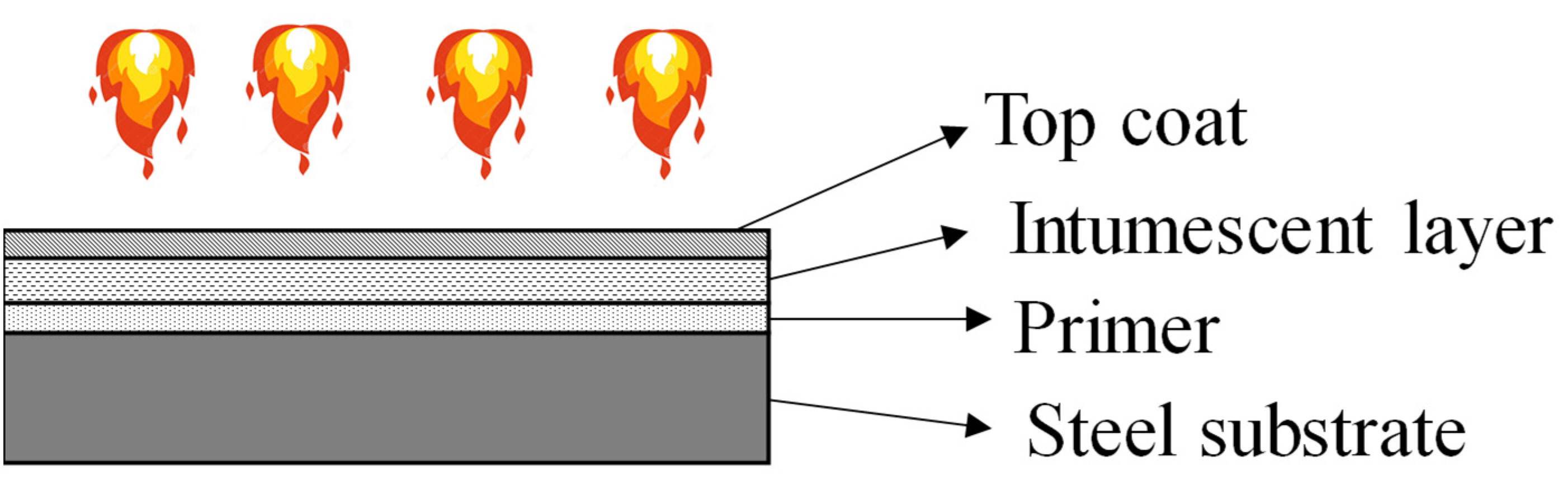
2. IC Technical Solution

ICs are always part of a system including an anticorrosive primer and, generally, a topcoat are used for steel structures. The primer ensures adhesion to the substrate in the normal state, anticorrosion protection, and stickability of the intumescent char formed during fire exposure, while the topcoat has both aesthetic function, and it is used to promote weathering resistance in end-use conditions (see Figure 1).
As also described before, this reactive protection, by swelling and forming a large number of small bubbles, acts as an insulating layer, with very small thermal conductivity, to protect the steel substrate from the high temperatures generated by the fire (see Figure 2).
The behavior of ICs subjected to elevated temperatures has been largely investigated in recent studies, especially from the chemical point of view. It is well known that the intumescent process is a complex chemistry including the organic (coating) binder resin and an acid catalyst like the ammonium polyphosphate, which decomposes to yield a mineral acid. This acid reacts with a carbonific source, such as pentaerythritol, to produce a carbon char. The melanine, which is a foam-producing agent, reacts with the acid source and decays, changing into an inert gas that then expands the char. This is the description of the main reactions that basically take place, although more complex interactions occur too. For example, filler particles are incorporated into the formulation to act as nucleating sites or “bubble growth” locations and the resin binder theatres a large part in softening and charring [12]. This chemical transformation affects the thermal properties of ICs [13]. Andersen [14] proposed the development of thermal resistance over time divided into four general phases, which were also confirmed and identified by de Silva et al. in [15], investigating the thermal conductivity and swelling of ICs (Figure 3).
The phases of IC behavior reported in Figure 3 are briefly described in the following.
1. Inert phase
Before reaching its reaction temperature, the dry IC is inert to the temperature and the thickness is equal to the initial one. During this phase, the IC is gradually melting and increasing its viscosity significantly. The thermal resistance provided to the steel is minimal and the measured protected temperature is similar to the unprotected one.
2. Transient phase
During the transient phase, the IC starts to swell and quickly increases in volume. When all the virgin material is consumed and the blowing agent is exhausted, a multicellular black char structure forms the IC. Generally, at this moment, the minimum thermal IC conductivity within the transient phase and the intumescent char is considered fully developed (see Figure 3). Furthermore, at this point, the char assembly is characterized by a black color due to the high carbon binder quantity. Later, the increase in the thermal IC’s conductivity is related to the gradual consumption of the carbon binder, which is the main component creating the char structure.
3. Steady phase
The endothermic reaction finishes when all the combustible materials burned and the IC pass in the steady phase. At this stage, only the white expanded char structure contributes to the thermal conductivity, keeping it to a constant value or sometimes it slightly increases.
4. Post-austenitization phase
For temperatures greater than 700 °C, after reaching the austenitization point, the IC char structure looks like a fragile and inconsistent material, characterized by a light white color. At this point, the carbon binder is all burned, and with that the char structure is degraded, losing its cohesion. During the post-austenitization phase and at high temperatures, the char structure starts to crack. The thermal IC conductivity increases by a steady value with a consequent increment in the steel temperature. The cracks act as thermal channels, and the char structure stops providing good insulation to the steel surface.

3. Qualification Process

The qualification process of ICs in Italy can follow a national or a European approach. In the first case, fire resistance shall be tested according to UNI EN 13381-8 [8], which contains a series of fire tests on steel elements protected with the IC that has to be qualified. In order to ensure free trade in the European market, the qualification process is regulated by EAD 350402-00-1106 [10] in the context of voluntary certification. Key points of both procedures are addressed in the following section in order to provide an overview of the main differences.

3.1. National Qualification Process

The UNI EN 13381-8 specifies a test method for determining the contribution of applied fire protection systems to structural steel members. This evaluation was designed to cover a range of thicknesses of ICs, a range of steel sections characterized by their section factors Am/V (which is the ration between the element surface exposed to fire Am and its total volume V), a range of design temperatures, and a range of valid fire protection classification periods. In particular, several steel elements have to be tested: unloaded tall columns and short columns, unloaded and loaded beams, and varying the section factors and the IC thickness. Generally, the beams are mounted to the ceiling of the furnace and the ends of the beams are protected in accordance with EN 13381-8:2013, and these beams are heated from three sides. The standard furnace is generally 4 m long and 3 m wide, equipped with several burners and controlled by a programmable logic controller to simulate different fire curves. Figure 4 shows an example of an arrangement in a furnace of fire tests conducted according to EN 13381-8:2013, in which the IC thickness varies between 1500 and 2500 μm.
This European Standard contains the fire test procedures that specify the tests that should be carried out to determine the efficiency of the fire protection system to remain attached to the steelwork and to provide data on the thermal properties of the fire protection system when exposed to the standard temperature/time curve specified in EN 1363-1 [16]. In some cases, the code require tests in furnaces under a slow heating curve in order to evaluate whether the performances of the ICs are affected by fire curves (Figure 5) with low thermal gradients (e.g., smoldering fire) [17]. If the ICs are used to protect structures in which the potential fire is similar to a hydrocarbon one, the standard curve appropriate to this fire has to be used.
In addition, current methods for testing and approving ICs for commercial use implicate the coating in a full-scale beam and column using a standard process in a furnace. This procedure must be repeated, even if the manufacturer has only made a minor change to the chemical formulation.
The fire test methodology makes provisions for the collection of data, which can be used as direct input into the calculation of the fire resistance of the steel structural members in accordance with the procedures given in EN 1993-1-2 [18] and EN 1994-1-2 [19]. This European Standard also contains the assessment, which prescribes how the analysis of the test data should be made and gives guidance on the procedures by which interpolation should be undertaken.
The assessment is performed in two main steps: first is the physical presentation, which is generally determined by evaluating the difference in temperature data between loaded and unloaded elements and checking if there is a negative influence from the application of a load. From this assessment, a temperature-dependent correction factor is calculated, which is applied to all the unloaded columns involved in the test set. These unloaded columns are in accordance with the standard tests included in the thermal performance evaluation.
The results of these tests and the assessment obtained according to this standard are directly applicable to steel sections of I and H cross-sectional shapes and hollow sections (see Figure 6).
The second step is the elaboration of the test data for the drafting of prescriptive tables useful for the design of the IC thickness as a function of required fire resistance, critical temperature, and section factor of the steel element (see Table 1). The critical temperature ranges between 500 and 600 °C and is the one at which the steel element loses its load-bearing capacity at a specific load; the higher the critical temperature, the lower the fire protection required by the structure.
This assessment prescriptive method treats ICs as chemically nonreactive materials, and it implicitly assumes that thermal properties only depend on the temperature, representing, in some cases, a limitation of IC use in design and verification methods.

3.2. European Qualification Process

The European qualification of reactive coating for fire protection of steel elements is regulated by the EAD 350402-00-1106 [10], published in the OJEU in 2017. This standard covers the reacting coating only or the reactive coating kit, composed of the primer for corrosion protection or as a bonding agent, the reactive component, and the topcoat (see Figure 1). The assessment methods included in the EAD refers to the fire protective coating element/kit with an intended working life from a minimum of 10 years up to 25 years. The product performances can be expressed through the assessment of the essential characteristics provided in Table 2.
Table 2. Essential characteristics and relative assessment methods for reactive coating systems according to EAD 350402-00-1106.
No.Essential
Characteristic
Assessment Method
Basic Work Requirement 2: Safety in case of fire
1Reaction to fireTest methods and classification according to EN 13501-1 [20]
2Resistance to fireTest methods and classification according to EN 13501-2 [21]
Basic Work Requirement 3: Hygiene, health, and the environment
3Content, emission, and/or release of dangerous substancesSVOCs and VOCs according to EN 16516
Basic Work Requirement 4: Safety and accessibility in use
4AdhesionInsulating efficiency tests according to EN 1363-1
5DurabilityInsulating efficiency tests on initial and exposed specimens according to EN 1363-1
Reaction to fire tests can be performed according to EN 13823 [22] or EN 11925-2 [23], applying the largest possible quantity of reactive fire protection on a steel surface with a thickness of at least 2 mm. The result of the tests applies to all reactive coating systems with application quantities smaller than or equal to the application quantity tested according to [22], including all primers and topcoats.
Fire resistance is assessed by means of the test method described in EN 13381-8 [5]. Because a reactive coating system does not possess fire resistance on its own, the classification applies to the protected element, including the reactive coating system, and not to the protection itself.
The performance of the product in terms of content, emission, and/or release of dangerous substances needs to be assessed on the basis of the intended release scenario that can be:
  • IA1: Product with direct contact to indoor air;
  • IA2: Product with indirect contact to indoor air but possible impact on indoor air;
  • S/W2: Product with indirect contact soil, ground, and surface water.
Semi-volatile organic compounds (SVOCs) and volatile organic compounds (VOCs) should be determined in accordance with EN 16516 [24].
The durability of the fire protective coating system is assessed with respect to service conditions, such as humidity, variations in temperature and relative humidity, rain and radiation of the sun, and chemical attacks. The durability assessment is achieved by means of indirect testing, i.e., through the measurement and comparison of insulating efficiency in initial (virgin) and exposed (to several conditioning) specimens. Insulating efficiency tests are performed according to a small-scale furnace fire test under the conditions of the standard time–temperature curve as defined in EN 1363-1 [16]. Specimens can be panels or I-section short columns. Fire tests finish when the specimen’s mean temperature reaches 500 °C. When the mean time to achieve the critical steel temperature t500 on exposed specimens is not less than 85% of the time t500 registered on virgin specimens, the durability is deemed to be met.
In order to ensure the required fire protective performance, adhesion of the reactive coating system to its substrate is fundamental. Adhesion is covered by testing the insulating efficiency as previously introduced.

4. Design and Control of the Application: Overview of Available Codes

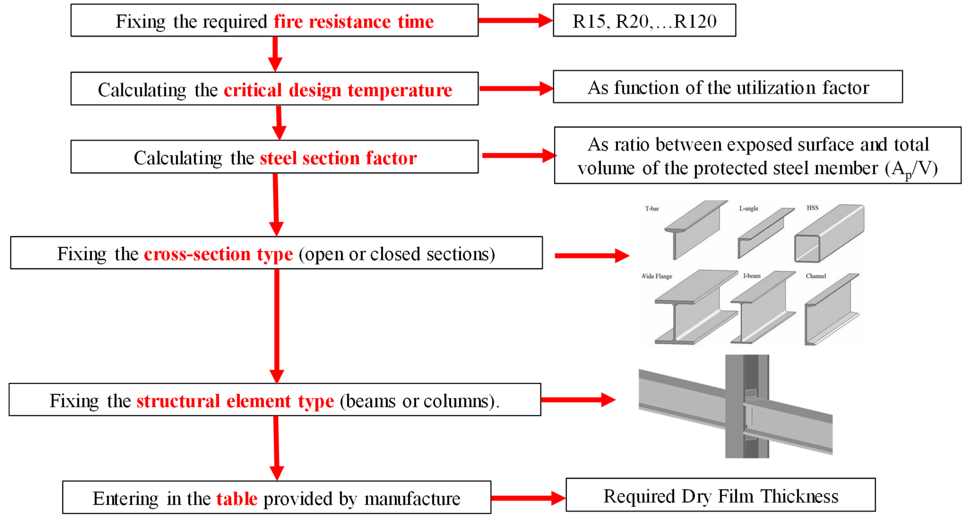
4.1. Design and Verification Methods with a Prescriptive-Based Approach

According to current regulations, the fire resistance of steel structures protected with intumescent coating is based on the standard fire resistance test, described before (EN 13381-8). Based on these results, tables that list the minimum dry film thickness (DFT) of the product required for achieving a certain fire resistance in terms of time are provided. In this way, the structural fire engineer can design or assess the fire resistance of the steel element protected with IC in a very simple way. In Figure 7, the main steps are described.
The Annex E of EN13381-8 describes another method to assess and design the fire resistance of steel structures protected with IC by using the effective thermal conductivity. This empirically informed procedure is called the “variable λ method”. It derives from an energy balance taken during a given time interval during heating for unidirectional heat flux conditions. This method is intended for evaluating the equivalent thermal conductivity of fire protection systems and is defined by the following expression:
λ I C = d I C × V A p × c a × ρ a × 1 ( θ t θ a , t ) × Δ t × Δ θ a , t
where:
  • dIC = dry film thickness of reactive product, in meters;
  • V/Ap = inverse of the steel section factor, in meters;
  • ca = temperature-dependent specific heat capacity of steel at θa, in J/kgK;
  • ρa = density of the steel, in kg/m3;
  • θt = furnace temperature, in Celsius degrees;
  • θa,t = steel temperature, in Celsius degrees;
  • Δt = time step, in seconds;
  • Δθa,t = steel temperature increase over time step Δt, in Kelvin degrees.
Figure 8 shows the typical development of the IC thermal conductivity calculated both with equation 1 and with simplified law, as suggested by de Silva et al. [25,26,27]. Starting from a thermal conductivity very similar to the steel one (λs), the IC one reaches a minimum value, and after it seems to stabilize. Knowing the thermal conductivity of the IC allows for the assessment of the behaviour of the protected steel elements using both simplified and advanced calculation methods. However, the effective thermal conductivity of IC is not only temperature dependent. Indeed, as demonstrated by researchers [15,26,27], it can also be dependent on the rate of heating, the steel section factor, the intumescent coating dry film thickness, and nonuniform temperature distribution within the intumescent coatings. These effects on the steel element temperature can be observed by analyzing Figure 9, obtained from an experimental campaign presented in [15]. In particular, it can be observed that when setting the section factor, the higher temperature was recorded in the sample protected by the smaller IC thickness.

4.2. Design and Verification Methods with a Performance-Based Approach

The new knowledge in the field of fire safety engineering (FSE) is directing the current regulations towards performance-based design. The design flexibility of this approach can enable the consideration of a safe and economical solution for the design of eventual fire protection for structures. Indeed, with this approach, natural fire curves are considered, according with the intended use of each part of the structure, geometry, ventilation, and distribution of the fire loads, in order to obtain fire scenarios and fire curves as representative as possible of the potential fire of the compartment (Figure 10).
As Figure 10 shows, natural fire curves can be very different from the ISO834 standard, and these differences, especially in the growth phase of the fire, can influence the behaviour of the reactive protections, such as the intumescent coatings, as demonstrated by numerous researchers [15,28]. This strongly indicates that it is not applicable to extrapolate the value of thermal properties, such as the thermal conductivity of IC obtained in accordance with the fire exposure condition in the current assessment method [EN 13381-8], to applications under different fire exposures. Since it is impossible to assess fire-resistance ratings for intumescent-coating-protected structural steel with an infinite number of combinations of parameters in a performance-based fire-resistance approach, it is crucial to characterize the fire performance of intumescent coating in different fire exposures and structure designs.
In actual technical regulations, this topic is generally not yet addressed, but in some countries, such as Italy, guidelines and technical references have been issued. Indeed, the DCPREV 9962 [29], enacted in July 2020, clarifies the use of fire protections with natural fire curves, prohibiting the design and assessment of steel elements protected with IC, as their behaviour under natural curves is unknown both in terms of thermal and mechanical properties (e.g., adhesion); this severely limits the adoption of FSE. In addition, in the FSE approach, advanced calculation methods are usually used for thermo-mechanical analyses and all the thermal properties have to be known including their variation with temperature. Right here, a problem arises; indeed, this variation is known only with standard fire curves used during the certification process in accordance with UNI EN 13381-8 as described before.
Even if numerous researchers have studied the behaviour of ICs under fire curves different from the nominal ones, it is clear that the problem of designing and assessing protected steel element by means of a performance-based approach is still open and more research is needed in order to generalize a common methodology for identifying the IC temperature-dependent thermal properties.

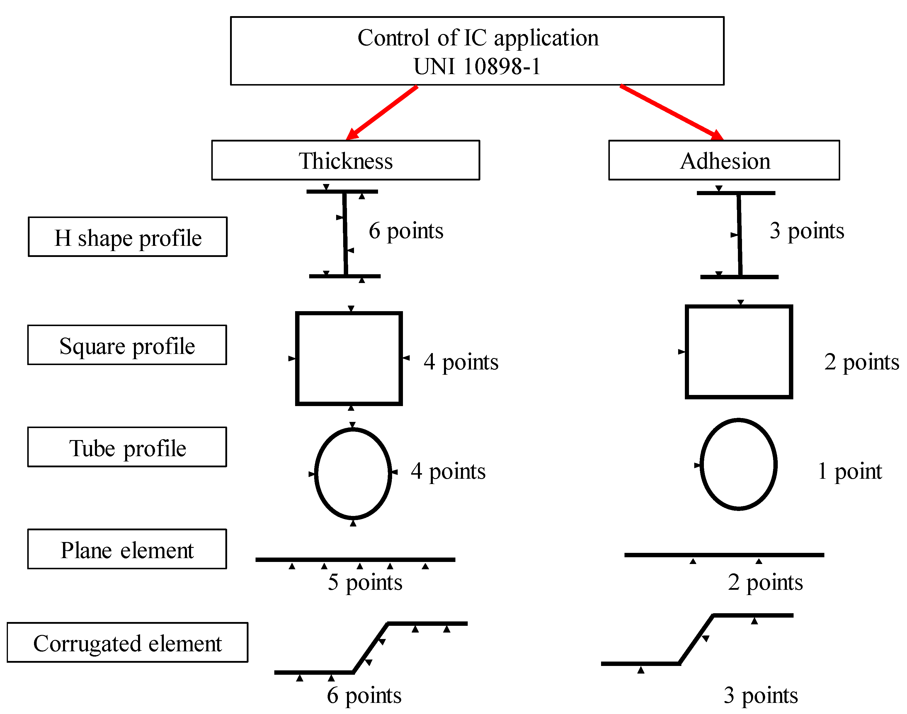
4.3. Control of IC Application

For its nature, the fire behaviour of IC mainly depends on dry film thickness (DFT), adhesion during normal and fire situation, and swelling reaction in fire situations. Therefore, in order to obtain a full characterization of these protections, several tests have to be performed before and after its application. All the surface properties are generally assessed according to several techniques, which are well described in [25].
While in the case of ICs, the UNI 10898-1 [30] establishes the methods for controlling the application of IC systems, suitable for checking their compliance with the project specifications, drawn up in operation of the element to be protected and the degree of fire resistance required (Figure 11).
The thickness consistency of the IC applied on an element can be measured according to UNI EN 2808 [31], which contains several methods for determining both the wet-film and dry-film thicknesses of generic coatings applied to a steel substrate.
The wet-film thickness has to be measured both during and immediately after applying the IC in order to verify the uniform application of each layer of the IC and the overall thickness. To measure the wet-film thickness, several alternative methods are suggested by UNI EN 2808 (see Figure 11). One of the most common methods is the use of a comb gauge, consisting of a flat plate made of a corrosion-resistant material with teeth along its edges (see Figure 12).
The reference teeth at the corners of the plate define a baseline along which the inner teeth are arranged to give a graduated series of gaps. Each tooth is labeled with the assigned gap value.
With commercially available comb gauges, the maximum thickness that can be measured is typically 2000 μm and the smallest increment is typically 5 μm.
After drying of the IC, it is necessary to check that the measured dry-film thickness is equal to the designed one as well as the uniformity of the IC application. In addition, in this case, the UNI EN 2808 suggests a series of measuring methods, which are summarized Figure 11. Among the suggested methods, two widely used ones are acoustic (ultrasonic thickness gauge) and optical instruments. The first type identifies the coating thickness by measuring the propagation time of the waves through the layer to be measured up to the steel substrate. Noninvasiveness and high precision are the advantages of using this instrument; moreover, the new generation ones are very simple to use, also in situ, after the application of the IC to the steel elements. The optical instrument allows for a direct measurement of the thickness up to the steel substrate via a slight cut on the painted surface. The blades are normalized, and the thickness can be obtained directly by reading the value through a graduated microscope. The instrument is slightly invasive, and it can be considered a good tool to check the measurements obtained by the ultrasonic one (Figure 13).
Another important parameter for the IC is the adhesion to the steel support and the compatibility between the layers of the protective package (i.e., primer, coating, and topcoat), which can be assessed according to UNI EN ISO 4624 [32]. In particular, the minimum tensile force necessary to detach the IC from the steel surface (adhesive failure) or the weakest layer of the IC system from the other ones (cohesive failure) has to be measured. The nature and preparation of the substrate and the IC type may influence the test results. Then, it is necessary to refer to standardized procedures (see Figure 14). The main steps for the preparation and execution of the test are summarized below:
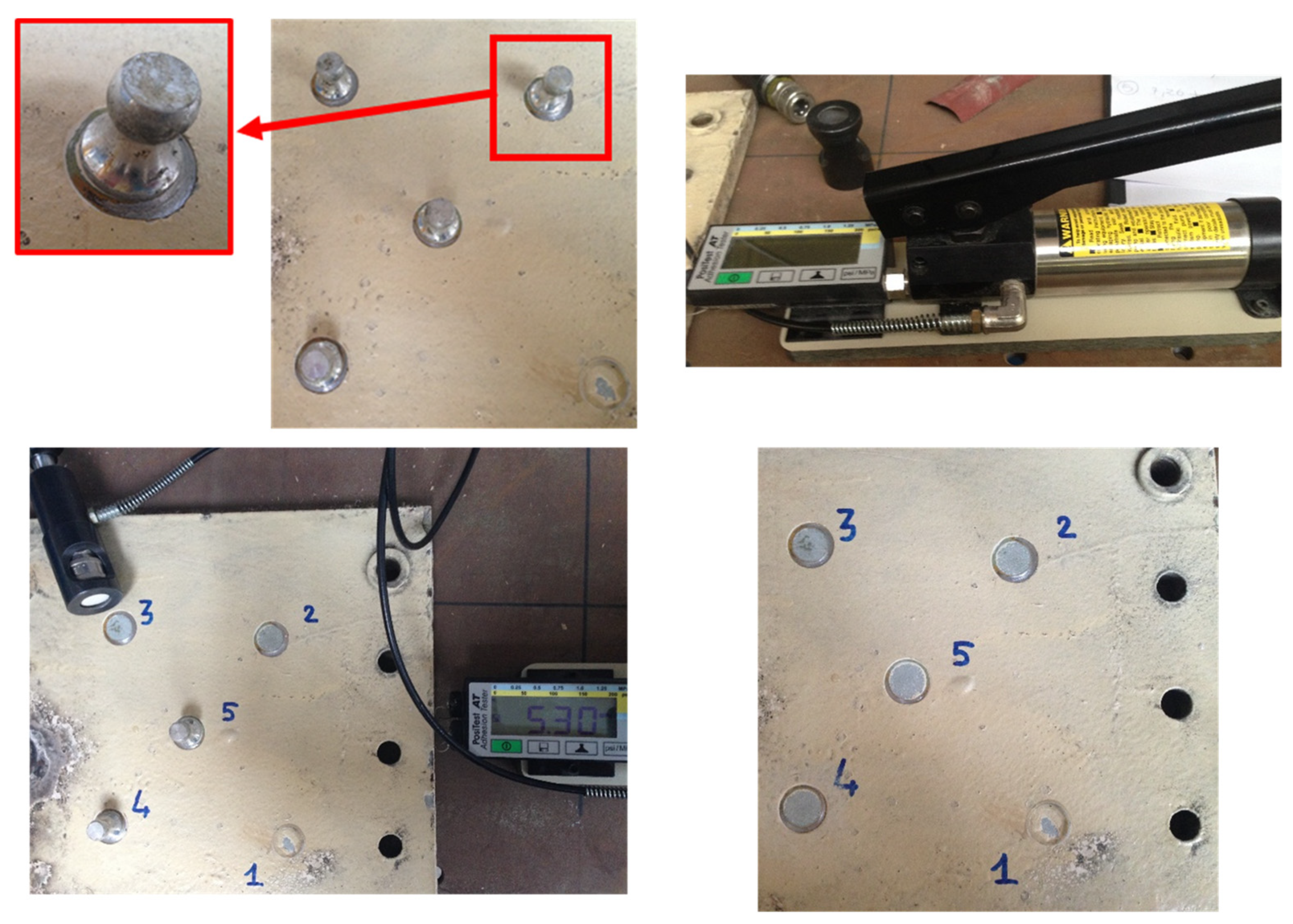
  • Step (a)—surface preparation: to guarantee the bond between the dolly and the coating, degrease the dolly and the area of the coating to be tested using alcohol or acetone to remove any oil, moisture, or dust;
  • Step (b)—application of adhesive: It must have cohesive and fixing properties greater than those of the coating under test in order to obtain a failing of the coating. The dolly should be gently pushed down to squeeze out excess adhesive and remove it from around the edges of the dolly (Figure 14). Finally, wait the necessary time for the adhesive to dry;
  • Step (c)—separation of test area: after the adhesive dries, before starting the test, the paint around the dolly should be removed to isolate a specific diameter test area. Generally, a drill with a diameter approximately 1 mm larger than the diameter of the dolly can be used;
  • Step (d)—load application: The contact between the dolly and the actuator should be carefully checked (Figure 14). The force must be applied perpendicularly to the plane of the coated support at a uniform speed, less than approximately 1 MPa/s.
Both thickness and adhesion tests, for the control of the IC application (UNI 10898-1), have to be carried out on several points of the element according to its shape (see Figure 15). After measuring, the conditions of acceptability have to be satisfied according to UNI 10898-1.

5. Conclusions

Intumescent coating is one of the most common materials for protecting steel structures from fire. Its particular nature of reactive material causes a thickness variation during the thermal transience with a decrease in its thermal conductivity. Even if this material is well studied in the literature from the chemical and physical points of view, a lack of information is sometimes found in the field of certification and design. Indeed, on one hand, the development of new products with always higher fire performance are required from the protection market; on the other hand, these protections should be compliant with the fire safety engineering approach in which natural fire curves are required. Therefore, the main objective of this paper was to provide a comprehensive overview of the certifications, design, and control of application procedures for the correct approach to the use of these fire protections, especially in Italy.
The qualification process of all materials and products employed for structural use is mandatory in Italy. Provided that performance assessment of IC systems is not covered by any harmonized standard, their quality certification can be pursued through a national assessment procedure, regulated by indications of the National Fire and Rescue Service by means of EN 13381-8:2013 or a European assessment procedure. The latter consists of a voluntary certification process to be undertaken with the guidance of a TAB and finally achieving the release of an ETA on the basis of EAD 350402-00-1106, i.e., a product code concerning the performance assessment of reactive coatings for fire protection of steel elements.
Regarding the IC design and control of application procedures, it emerges that:
-
The data provided by manufacturers allow for application on only a prescriptive-based approach, obtaining, trough tabular data, the IC thickness necessary for a given structural element to reach a required fire resistance time;
-
Generally, no information is provided about the thermal properties of these materials;
-
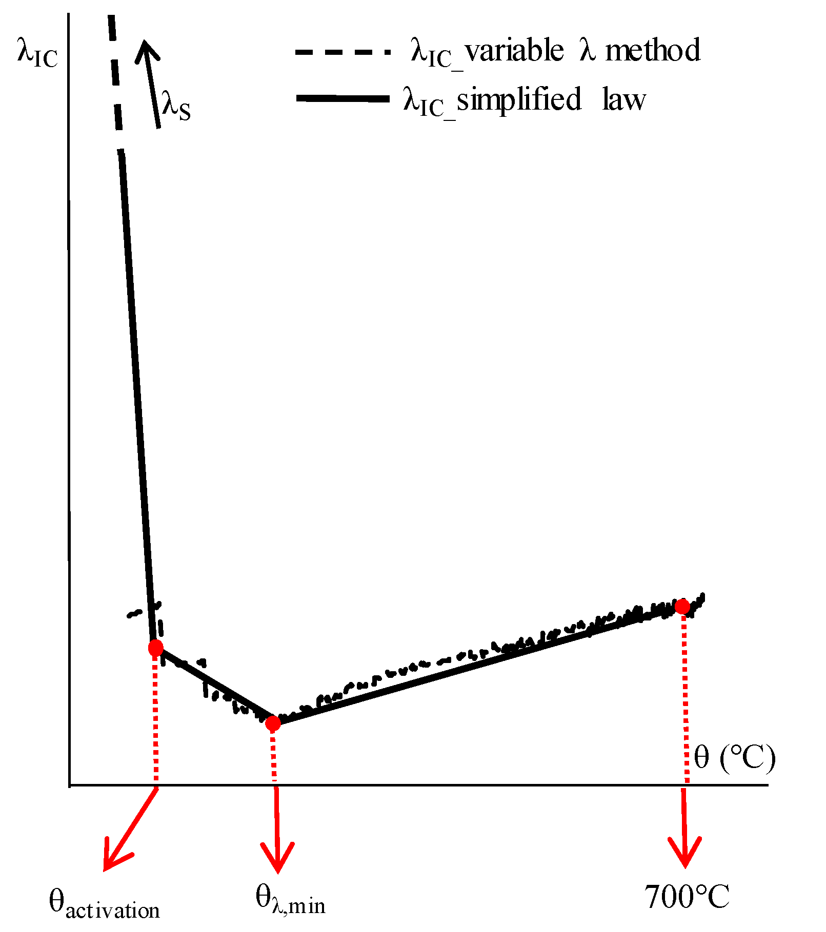
According to EN 13381-8, a variable thermal conductivity can be calculated starting from the experimental results, allowing to assess the behaviour of the protected steel elements using both simplified and advanced calculation methods if the ISO834 curve is used;
-
The voluntary application regulations describing the control of intumescent coating application are often ignored and not applied.
Another important conclusion is that, at the moment in Italy, to model steel structures protected with intumescent coating is forbidden if the modern fire safety engineering approach is used, because not much information is available on the behaviour of intumescent systems under natural fire curves. Therefore, it is necessary to carry out experimental tests in order to investigate the performance of the intumescent coating under fire curves with different heating rates in order to identify a common methodology for the definition of IC temperature-dependent thermal properties.

Funding

This research received no external funding.

Institutional Review Board Statement

Not applicable.

Informed Consent Statement

Not applicable.

Data Availability Statement

Not applicable.

Conflicts of Interest

The authors declare no conflict of interest.

References

  1. Beh, J.H.; Yew, M.C.; Saw, L.H.; Yew, M.K. Fire Resistance and Mechanical Properties of Intumescent Coating Using Novel BioAsh for Steel. Coatings 2020, 10, 1117. [Google Scholar] [CrossRef]
  2. Lucherini, A.; Maluk, C. Intumescent coatings used for the fire-safe design of steel structures: A review. J. Constr. Steel Res. 2019, 162, 105712. [Google Scholar] [CrossRef]
  3. An Overview of Intumescent Coatings. American Coating Association. Available online: https://www.paint.org/coatingstech-magazine/articles/overview-intumescent-coatings/ (accessed on 18 April 2022).
  4. Hernandez, V.; Romero, R.; Arias, S.; Contreras, D. A Novel Method for Calcium Carbonate Deposition in Wood That Increases Carbon Dioxide Concentration and Fire Resistance. Coatings 2022, 12, 72. [Google Scholar] [CrossRef]
  5. Luhar, S.; Nicolaides, D.; Luhar, I. Fire Resistance Behaviour of Geopolymer Concrete: An Overview. Buildings 2021, 11, 82. [Google Scholar] [CrossRef]
  6. Norme Tecniche per le Costruzioni—NTC2018; Decreto del 17 Gennaio 2018; Gazzetta Ufficiale n. 42 del 20 Febbraio 2018. (In Italian). Available online: https://www.gazzettaufficiale.it/eli/gu/2018/02/20/42/so/8/sg/pdf (accessed on 18 April 2022).
  7. Construction Products Regulation (CPR)—Regulation (EU) No 305/2011 of the European Parliament and of the Council of 9 March 2011; Official Journal of the European Union. Available online: https://eur-lex.europa.eu/legal-content/EN/TXT/PDF/?uri=CELEX:32011R0305&rid=2 (accessed on 18 April 2022).
  8. EN 13381-8; Test Methods for Determining the Contribution to the Fire Resistance of Structural Members—Part 8: Applied Reactive Protection to Steel Members. European Committee for Standardization: Brussels, Belgium. Available online: https://standards.iteh.ai/catalog/standards/cen/df0cdd6b-9ef2-47fc-874b-414ae34aa5cc/en-13381-8-2013 (accessed on 18 April 2022).
  9. Qualificazione di Resistenza al Fuoco di Protettivi da Applicare ad Elementi in Acciaio; Lettera Circolare n°17381 of 2013; Ministero dell’interno–Dipartimento dei Vigili del Fuoco, del Soccorso Pubblico e Della Difesa Civile. Direzione Centrale per la Prevenzione e la Sicurezza Tecnica–Area Protezione Passiva: Rome, Italy, 2013. (In Italian)
  10. EAD 350402-00-1106; Reactive Coatings for Fire Protection of Steel Elements. EOTA: Brussels, Belgium, 2017.
  11. ETAG 018; Part 2. Guideline for European Technical Approval of Fire Protective Products. Part 2: Reactive Coatings for Fire Protection of Steel Elements. EOTA: Brussels, Belgium, 2006.
  12. Bourbigot, S.; Bras, M.L.; Dabrowski, F.; Gilman, J.W.; Kashiwagi, T. PA-6 clay nanocomposite hybrid as char forming agent in intumescent formulations. Fire Mater. 2000, 24, 201–208. [Google Scholar] [CrossRef]
  13. Kang, S.; Kwon, M.; Choi, J.Y.; Choi, S. Thermal Boundaries in Cone Calorimetry Testing. Coatings 2019, 9, 629. [Google Scholar] [CrossRef] [Green Version]
  14. Andersen, J. Experimental Study of the Thermal Resistance of Intumescent Coatings Exposed to Different Heating Rates. Master’s Thesis, Civil Engineering Department, Technical University of Denmark, Copenhagen, Denmark, 2015. [Google Scholar]
  15. De Silva, D.; Bilotta, A.; Nigro, E. Experimental investigation on steel elements protected with intumescent coating. Constr. Build. Mater. 2019, 205, 232–244. [Google Scholar] [CrossRef]
  16. EN 1363-1; Fire Resistance Tests—Part 1: General Requirements. CEN-CENELEC Management Centre: Brussels, Belgium, 2020.
  17. De Silva, D.; Bilotta, A.; Nigro, E. Effect of the thermal input on the behavior of intumescent coatings. In Proceedings of the International Conference of Applications of Structural Fire Engineering, Manchester, UK, 7–8 September 2017; pp. 325–334. [Google Scholar]
  18. EN 1993-1-2; Eurocode 3: Design of Steel Structures—Part 1–2: General Rules-Structural Fire Design. CEN-CENELEC Management Centre: Brussels, Belgium, 2005.
  19. EN 1994-1-2; Eurocode 4—Design of composite steel and concrete structures—Part 1–2: General rules-Structural Fire Design. CEN-CENELEC Management Centre: Brussels, Belgium, 2005.
  20. EN 13501-1; Fire Classification of Construction Products and Building Elements—Part 1: Classification Using Test Data from Reaction Fire Tests. CEN-CENELEC Management Centre: Brussels, Belgium, 2018.
  21. EN 13501-2; Fire Classification of Construction Products and Building Elements—Part 1: Classification Using Test Data from Resistance Fire Tests. CEN-CENELEC Management Centre: Brussels, Belgium, 2016.
  22. EN 13823; Reaction to Fire Tests for Building Products—Building Products Excluding Floorings Exposed to the Thermal Attack by a Single Burning Item. CEN-CENELEC Management Centre: Brussels, Belgium, 2020.
  23. EN ISO 11925-2; Reaction to Fire Tests—Part 2: Ignitability of Products Subjected to Direct Impingement of Flame. ISO: Brussels, Belgium, 2020.
  24. EN 16516; Construction Products—Assessment of Release of Dangerous Substances–Determination of Emissions into Indoor Air. CEN-CENELEC Management Centre: Brussels, Belgium, 2017.
  25. De Silva, D.; Alam, N.; Nadjai, A.; Nigro, E.; Ali, F. Finite Element Modelling for Structural Performance of Slim Floors in Fire and Influence of Protection Materials. Appl. Sci. 2021, 11, 11291. [Google Scholar] [CrossRef]
  26. De Silva, D.; Bilotta, A.; Nigro, E. Approach for modelling thermal properties of intumescent coating applied on steel members. Fire Saf. J. 2020, 116, 103200. [Google Scholar] [CrossRef]
  27. Zhang, C.; Li, G.Q.; Wang, Y.-C. Probabilistic analysis of steel columns protected by intumescent coatings subjected to natural fires. Struct. Saf. 2014, 5, 16–26. [Google Scholar] [CrossRef]
  28. Lucherini, A.; Giuliani, L.; Jomaas, G. Experimental study of the performance of intumescent coatings exposed to standard and non-standard fire conditions. Fire Saf. J. 2018, 95, 42–50. [Google Scholar] [CrossRef] [Green Version]
  29. Circolare DCPREV 9962 del 24/07/2020—Implementazione di Soluzioni Alternative di Resistenza al Fuoco; Chiarimenti e Indirizzi Applicativi; Ministero dell’interno—Dipartimento dei Vigili del Fuoco, del Soccorso Pubblico e Della Difesa Civile. Direzione Centrale per la Prevenzione e la Sicurezza Tecnica,–Area Protezione Passiva: Rome, Italy, 2020. (In Italian)
  30. UNI 10898-1; Fire Proofing Systems—Inspection Modes for the Installation—Part 1: Intumescent Coating. UNI: Milano, Italy, 2012.
  31. EN 2808; Paint and Varnishes—Determination of Film Thickness. CEN-CENELEC Management Centre: Brussels, Belgium, 2007.
  32. EN ISO 4624; Paint and Varnishes—Pull-Off Test for Adhesion. CEN-CENELEC Management Centre: Brussels, Belgium, 2006.
Figure 1. Intumescent system.
Coatings 12 00696 g001
Figure 2. Fire behavior of ICs.
Coatings 12 00696 g002
Figure 3. Common trends in the thermal equivalent conductivity and IC swelling and definition of the four general phases in their development.
Coatings 12 00696 g003
Figure 4. Typical disposition of specimens for a fire test according to EN 13381-8.
Coatings 12 00696 g004
Figure 5. Fire curves.
Coatings 12 00696 g005
Figure 6. Specimens’ temperatures measured during the fire test.
Coatings 12 00696 g006
Figure 7. The main step for designing IC thickness.
Coatings 12 00696 g007
Figure 8. IC thermal conductivity calculated with accurate (EN 13381-8) and simplified laws.
Coatings 12 00696 g008
Figure 9. The temperature evolution in steel samples.
Coatings 12 00696 g009
Figure 10. Natural fire curve compared with the ISO834 one.
Coatings 12 00696 g010
Figure 11. Methods for assessing the correct IC application.
Coatings 12 00696 g011
Figure 12. Example of a comb gauge.
Coatings 12 00696 g012
Figure 13. Example of DFT measurement gauges.
Coatings 12 00696 g013
Figure 14. Example of DFT measurement gauges.
Coatings 12 00696 g014
Figure 15. Measurement points for checking.
Coatings 12 00696 g015
Table 1. Typical table for the prescriptive design of IC thickness.
Fire Resistance Classification
Critical temperature (°C)350400450500550600650
Section factor A/V (m−1)Thickness of IC (μm)
70600400400400400400400
75600400400400400400400
80600400400400400400400
85600400400400400400400
90600400400400400400400
95750400400400400400400
100750400400400400400400
105750400400400400400400
Publisher’s Note: MDPI stays neutral with regard to jurisdictional claims in published maps and institutional affiliations.

