Article

Wear Resistance, Patterns of Wear and Plastic Properties of Cr,Mo-(Cr,Mo,)N-(Cr,Mo,Al)N Composite Coating with a Nanolayer Structure

by
Alexey Vereschaka
1,*,
Anton Seleznev
2 and
Vladislav Gaponov
2
1
Institute of Design and Technological Informatics of the Russian Academy of Sciences (IDTI RAS), 127055 Moscow, Russia
2
VTO Department, Moscow State Technological University STANKIN, 127994 Moscow, Russia
*
Author to whom correspondence should be addressed.
Coatings 2022, 12(6), 758; https://doi.org/10.3390/coatings12060758
Submission received: 5 May 2022 / Revised: 28 May 2022 / Accepted: 31 May 2022 / Published: 31 May 2022
(This article belongs to the Special Issue Technologies of Coatings and Surface Hardening for Tool Industry II)

Abstract

:
This paper discusses the results of studies focused on the wear resistance, patterns of wear and plastic properties of Cr,Mo-(Cr,Mo,)N-(Cr,Mo,Al)N coating, containing 20 at.% Mo. The coating had a nanolayer structure with a modulation period λ = 50 nm. The studies revealed the hardness, fracture resistance in scratch testing, as well as elemental and phase composition of the coating. The studies of the tool life of carbide cutting tools with the Cr,Mo-(Cr,Mo,)N-(Cr,Mo,Al)N coating proved their longer tool life compared to that of uncoated tools and tools with the reference Cr-(Cr,Al)N coating of equal thickness and equal content of aluminum (Al). The studies included the comparison of the tools coated with Cr,Mo-(Cr,Mo,)N-(Cr,Mo,Al)N and Cr-(Cr,Al)N. The experiments focused on the specific features of the coating nanostructure and were conducted using a transmission electron microscope (TEM), revealing the different mechanisms of fracture. The penetration of particles of the material being machined between nanolayers of the coating results in interlayer delamination. When exposed to a moving flow of the material being machined, plastic deformation (bending) of the coating nanolayers occurs. The diffusion of iron into the coating (up to 200 nm) and diffusion of Cr and Mo into the cut material to a depth of up to 250 nm are observed. The presented information can help in the design of metal cutting tools and the choice of coatings for them.

1. Introduction

One of the most efficient ways to enhance the performance properties of materials is to modify their surface parameters by the deposition of special coatings [1,2,3,4]. Similar materials, composite in nature, including substrates and coatings, are increasingly used in products for various purposes (cutting tools, friction pairs, medical implants, etc.).
The production of metal-cutting tools is one of the spheres where modifying coatings is widely used. Modern machine equipment allows machining with high efficiency. In particular, the cutting speed can be increased considerably without loss of system rigidity. The cutting tool is a weak link in cutting system technology, which limits the further growth of cutting speeds and machining [5,6,7]. New tool materials, including composite materials consisting of a substrate and a coating, are introduced in order to improve the characteristics of cutting tools. At the same time, the coatings themselves are improved due to the development of a more complex structure and composition [8,9,10]. In particular, the introduction of additional elements into the coating composition can increase its hardness, heat resistance, and, finally, its general ability to resist wear [11,12,13,14,15,16,17,18].
Coatings based on the (Crx,Al1-x)N system are widely used, and they provide good wear properties for tools during cutting [19,20,21,22]. The additional increase in the characteristics of the considered coating can be obtained due to the introduction into its composition of such elements as molybdenum (Mo), niobium (Nb), boron (B), vanadium (V), tantalum (Ta), yttrium (Y), as well as silicon (Si) [23,24,25,26,27,28]. Several studies demonstrate that the most favorable properties can be ensured with the introduction of molybdenum, simultaneously providing an increase in hardness, heat resistance, and an improvement of its tribological properties due to the formation of MoO3 oxides at high temperatures [28,29,30,31].
On the other hand, coatings based on the (Crx,Mo1−x)N system are characterized not only by sufficient hardness and heat resistance but also by excellent tribological properties at high temperatures due to the possibility of the formation of MoO3 oxide films [32,33,34]. In the considered system, molybdenum performs the functions described above by providing thermal stability and improving tribological properties. In particular, with the introduction of 17 at.% Mo into the considered system, the temperature threshold of the start of active oxidation increases considerably in comparison with the CrN coating [32]. The presence of molybdenum also contributes to the preservation of a dense columnar structure upon heating to at least 700 °C, while at the same temperatures, the columnar structure of the CrN coating begins to fracture with the growth of internal stresses, which results in the destruction of the coating on separate fragments [32,34]. On the coating surface, a film of MoO3 begins to form at a temperature of 600 °C, performing at the same time the protective (prevention of further oxidation) and lubrication (decrease in the coefficient of friction) functions [32,34]. With the introduction of molybdenum into the composition of the (Crx,Mo1−x)N system, a substitution solid solution based on the cubic structure of CrN is formed, but with an increase in the content of Mo, a phase of γ-Mo2N is also detected. When the content of Mo is prevailing (69.3 at.%), a certain amount of the bcc-Mo phase also arises [35]. Changes in the phase composition of the coating also affect its mechanical properties. In particular, the introduction of molybdenum into the composition of the system increases the hardness of the coating, but with an increase in the Mo content to 45 at.% and above, a decrease in hardness is detected [35,36].
When comparing the available data on the hardness of CrN and Mo2N, it can be concluded that despite a wide variety of data on the hardness of these materials, the hardness of Mo2N is still slightly higher (19–51 GPa [37,38,39,40,41,42]) than the hardness of CrN (16–27 GPa [43,44,45]).
The introduction of aluminum into the composition of the coatings provides a considerable improvement in their properties due to the formation of a substitution solid solution with the distortion of the crystal lattice, as the atomic radius of aluminum is noticeably smaller than those of titanium (Ti), chromium (Cr), or molybdenum (Mo). In particular, the experiments reveal that the (Cr,Al,Mo)N coating is characterized by higher heat resistance and hardness than the (Cr,Mo)N coating [28,29,30,31,46]. In addition to the described advantages, the (Cr,Al,Mo)N coating also demonstrates good tribological properties at high temperatures due to the formation of oxide films based on Cr2O3, Al2O3, and MoO3 [28,29,30,31,46]. The coating hardness slightly decreases with an increase in the content of Mo [47,48,49] (37 GPa with the Mo content of 7 at.% [47], 35 GPa with the Mo content of 24 at.% [48], and 34 GPa with the Mo content of 41 at.% [48]). Meanwhile, the hardness is still much higher than the hardness of the (Cr,Al)N coating (29 GPa [47,49]). It is reported that with the introduction of a small amount of molybdenum (4 at.%), there is a slight decrease (by 1 GPa) in the coating hardness compared to the coating containing no molybdenum [49].
A decrease in the coefficient of friction is even more noticeable (from 0.90 for the (Cr,Al)N coating to 0.48 for the (Cr,Al,Mo)N coating with 33.2 at.% Mo [48]), which can be associated with the active formation of the above-mentioned phase of MoO3. It is also important that the formation of tribologically active oxides in the (Cr,Al,Mo)N coating starts at lower temperatures than in the (Cr,Al)N coating. This fact can be explained by the lower temperature of molybdenum nitride oxidation and, accordingly, the formation of MoO3, compared to the temperatures of oxidation of (Cr,Al)N and formation of Cr2O3 and Al2O3.
In addition to the elemental composition, the properties of the coatings are significantly affected by the parameters of the coating structure. The transition to the multilayer structure additionally increases the key properties of the coatings [50,51,52]. The application of the multilayer structure with a nanometric thickness of layers improves the properties of the coating, such as resistance to cracking and brittle fracture [51,52], as well as tribological properties [52]. Earlier studies of the coatings based on the (Cr,Mo,Al)N system (in particular, Ti-TiN-(Ti,Cr,Mo,Al)N [53], Cr,Mo-(Cr,Mo,Zr,Nb)N-(Cr,Mo,Zr,Nb,Al)N [11], and Cr,Mo-(Cr,Mo)N-(Cr,Mo,Al)N [10]) proved their high efficiency as coatings for cutting tools.
The choice of molybdenum content in the coating was associated with the need to provide a balanced combination of properties. On the one hand, if the content of molybdenum is too low, there is no noticeable change in the tribological properties since a sufficient amount of molybdenum oxide is not formed [48]. On the other hand, an excessive increase in the content of molybdenum (more than 45 at.%) leads to a decrease in the hardness of the coating [35,36,48]. The temperature threshold for the onset of active oxidation noticeably increases at a content of 17 at.% Mo [32]. Based on the above, the molybdenum content was chosen to be about 20 at.%. Thus, the Cr,Mo-(Cr,Mo)N-(Cr,Mo,Al)N coating with three-layer architecture was chosen for the present study [54,55]. The adhesive layer of Cr,Mo provides high adhesion to the substrate and smooths out the surfaces of the substrate by filling places of microroughness. The transition layer of (Cr,Mo)N solves the problem of a smooth transition of the properties from the adhesive layer to the wear-resistance layer, and the wear-resistant layer of (Cr,Mo,Al)N, which, in turn, has a nanolayer structure, provides resistance to wear and optimization of the contact conditions in the cutting zone [16].

2. Materials and Methods

The coating of Cr,Mo-(Cr,Mo)N-(Cr,Mo,Al)N was deposited with the specialized VIT-2 unit (IDTI RAS—MSTU STANKIN, Moscow, Russia) using evaporators operating under filtered cathodic vacuum arc deposition (FCVAD) technology [54,56,57,58,59,60,61] (for an aluminum cathode) and Controlled Accelerated Arc (CAA-PVD) [62] (for cathodes of chromium and molybdenum). Three cathode systems were used, including cathodes of Al (99.8%, installed in the FCVAD system), cathodes of Cr,Mo (50 + 50%), and cathodes of Cr (99.9%, installed in the CAA-PVD systems). The cathode of Al (99.8%) and two cathodes of Cr (99.9%) were used to deposit the reference coating of Cr-(Cr,Al)N.
The Cr,Mo-(Cr,Mo)N-(Cr,Mo,Al)N coating had the following functional layer parameters: the Cr,Mo adhesive layer, 20–50 nm thick, the (Cr,Mo)N transition layer, about 700 nm thick, and the (Cr,Mo,Al)N wear-resistant layer, about 2000 nm thick. Thus, the total thickness of the Cr,Mo-(Cr,Mo)N-(Cr,Mo,Al)N coating was about 2750 nm. For the reference Cr-(Cr,Al)N coating, the thickness of the Cr adhesive layer was 20–50 nm, and the thickness of the (Cr,Al)N layer was 2600–2800 nm. Thus, the coatings under comparison had equal total thickness. The layers of (Cr,Mo,Al)N and (Cr,Al)N had a nanolayer structure with a modulation period λ = 45–50 nm.
The conditions of the coating deposition are presented in Table 1.
The characteristics of the nanolayer structure of the coatings (the thickness of the nanolayers and the nanolayer period) were determined by the rotation speed of the turntable (n = 0.7 rpm), the deposition time, and the process parameters [16].
Carbide inserts SNUN ISO 1832:2012 (WC + 15% TiC + 6% Co) were used as a substrate. Sample preparation consisted of washing the samples in a special solution with ultrasonic assistance, rinsing in distilled water, and drying. No additional impact on the samples (for example, polishing) was carried out. Thus, the technological sequence of sample preparation and coating deposition fully corresponded to the real conditions for the production of metal-cutting tools.
A JEM 2100 (JEOL Company, Tokyo, Japan) transmission electron microscope (TEM) was used to study the structure; the accelerating voltage was 200 kV. The elemental composition was determined by TEM with an EDX INCA Energy (OXFORD Instruments, Abingdon, Oxfordshire, UK) system. Samples (lamellae) were cut using a focused ion beam (FIB) on Strata 205 (FEI, Hillsboro, OR, USA) equipment.
Resistance of samples to wear was determined during the turning of 1045 steel at a CU 500 MRD lathe (ZMM-BULGARIA HOLDING, Sofia, Bulgaria) with a ZMM CU 500 MRD variable-speed drive at dry cutting. Geometric parameters of the cutting process were as follows: γ = −7°, α = 7°, λ = 0, r = 0.4 mm; at cutting mode: f = 0.1 rpm, ap = 0.5 mm, and vc = 400 m/min. A tool with the reference coating of Cr-(Cr,Al)N and an uncoated tool were considered for comparison. For each type of cutting tool (coated or uncoated), five cutting tests were carried out. The presented wear graph shows the average wear values for five tests. The corresponding error bars show the spread of values. Four experiments were conducted for each coating, and the obtained values of flank wear were processed to obtain the polynomial functions exhibited on the curve. The limit wear criterion was assumed as VBmax = 0.4 mm.
Wear resistance was studied when turning steel 1045 on a CU 500 MRD (ZMM-BULGARIA HOLDING, Sofia, Bulgaria) lathe with a ZMM CU 500 MRD variator, under dry cutting conditions. The following cutting geometry was used: γ = −7°, α = 7°, λ = 0, r = 0.4 mm; with cutting parameters: f = 0.1 rpm, ap = 0.5 mm, vc = 400 m/min. As objects of comparison, we used a tool with a commercial coating of Cr-(Cr,Al)N and without a coating. For each type of coating, five tests were carried out under similar conditions. The graphs show average wear values, the spread of values is described by error bars. The wear limit criterion was assumed to be VBmax = 0.4 mm.
To measure the hardness of the coatings, a mechanical tester (CSM Instruments, Needham, MA, USA) was used, the Oliver–Pharr method [63] was used, and the load was 10 mN. Scratch fracture resistance was determined according to ASTM1624-05 [64] on a Nanovea M1 (Micro Scratch, Nanovea, Irvine, CA, USA). The value of the critical load LC2, which characterizes the beginning of the complete destruction of the coating, was determined by the method of acoustic emission. When choosing parameters and research methods, the data presented in [65,66,67,68,69,70,71,72,73,74] were taken into account.

3. Results

Research results prove that its wear-resistant layer contains on average (given a change in the proportion of elements over the thickness of each nanolayer) 70 (±12) at.% Cr, 20 (±11) at.% Mo, and 10 (±5) at.% Al (Figure 1a). On the presented diffraction patterns, copper is the peak from the copper mesh on which the lamella is attached. A single phase of c-(Cr,Mo,Al)N is detected in the wear-resistant layer of the coating (Figure 1b). The reference coating of CrAlN contains 89 (±2) at.% Cr and 11(±2) at.% Al.
The hardness of the Cr,Mo-(Cr,Mo)N-(Cr,Mo,Al)N coating (27.6 ± 0.9 GPa) is slightly lower than the hardness of the Cr-(Cr,Al)N coating (30.0 ± 1.1 GPa), with equal values of the critical load of destruction LC2 for both coatings (40 N). The study of the structure of the Cr,Mo-(Cr,Mo)N-(Cr,Mo,Al)N coating reveals nanolayer construction with a modulation period λ = 50 nm (Figure 1c). The nanolayer structure has a complex construction with variable thickness of nanolayers formed during the planetary rotation of the sample in the unit chamber [16].
The study of wear resistance of the cutting tool finds (Figure 2) that the uncoated tool has a very short tool life at the given cutting modes. The tool with the Cr,Mo-(Cr,Mo)N-(Cr,Mo,Al)N coating demonstrates the best wear resistance both along the rake and flank faces compared to the tool with the Cr-(Cr,Al)N coating and the uncoated tool.
The study of the wear dynamics on the rake face of the tool reveals a noticeably more active formation of wear crater on the tool with the Cr-(Cr,Al)N coating compared to the tool with the Cr,Mo-(Cr,Mo)N-(Cr,Mo,Al)N coating (Figure 3). The formation of a wear crater on the rake face is typical both for the Cr-(Cr,Al)N-coated and Cr,Mo-(Cr,Mo)N-(Cr,Mo,Al)N-coated tools, but the process is more intensive for the Cr-(Cr,Al)N-coated tool. There is a more intensive formation of the wear crater and noticeable differences in its geometry. In contrast, for the tool with the Cr,Mo-(Cr,Mo)N-(Cr,Mo,Al)N coating, the edge of the wear crater, far from the cutting edge, resembles a circular arc, then for the tool with the Cr-(Cr,Al)N coating, an almond-like shape of the wear crater is typical. In turn, this (almond-like) shape of the crater is typical for the high cutting speeds and, accordingly, high temperatures in the cutting zone [3,4,75,76]. Thus, it can be assumed that during cutting with the Cr,Mo-(Cr,Mo)N-(Cr,Mo,Al)N-coated tool, the temperature in the cutting zone is slightly lower compared to the temperature during the cutting with the Cr-(Cr,Al)N-coated tool.
For the more detailed studies of the wear processes on the tool with the Cr,Mo-(Cr,Mo)N-(Cr,Mo,Al)N coating, lamella A (see Figure 3) is cut out, which intersects the coating fracture area on the edge of the wear crater, far from the cutting edge.
Figure 4a depict the “cut material flow-coating” interface. Particles of the material being machined (steel) penetrate into the coating structure. Plastic deformation (bending) of the structure of coating nanolayers takes place due to the adhesive contact between the cut material flow and the coating (Figure 4c).
The structure of the material being machined (steel) can include not only a softer fraction of iron but also harder carbonaceous (for example, martensite) fractions, as well as hard oxide grains [77,78,79]. These solid particles can affect the structure of the coating (Figure 5). In particular, such particles wedge between the coating nanolayers, resulting in plastic deformation and delamination of the nanolayers.
Figure 6 exhibit an example of the steel penetrating into the coating of the structure. A particle of the machined steel wedges between the coating nanolayers to a depth of no more than 200 nm, breaking the bond between the outer nanolayer, rich in aluminum (light in contrast), and the main structure of the coating. In terms of the interdiffusion processes between the machined steel and the coating (Line L1, Figure 6a), there is the iron diffusion into the coating structure to the depth of no more than 200 nm and the chromium and molybdenum diffusion into the structure of the machined steel to the depth no more than 250 nm (Figure 6d). The Fourier analysis (Figure 6c) of the “coating-material being machined” interface reveals the presence of F m 3 ¯ m , the main phase of the (Cr,Mo,Al)N coating, and Im3m, the phase of iron.
The cut material flow has a diverse effect on the structure of the coating. In particular, Figure 7b depict the fracture of a fragment in the coating nanolayer. It can be assumed that later, the fragment could be completely separated from the coating structure and carried away by the cut material flow. Along with the earlier considered mechanism when particles of the machined steel wedge between the nanolayers of the coating, the described mechanism of fracture and separation of fragments from the coating can affect the general pattern of wear of the coating.
Another example of the effect of the cut material flow on the coating structure is the rounding of the ends of the collapsing nanolayers. The described effect results in the formation of a fan-like structure exhibited in Figure 7c.
The study of the boundary between the contact of the cut material flow and the coating reveals the presence of the grains of c-(Cr,Mo,Al)N in the coating, while both grains of iron and harder grains of oxide iron (see Figure 8) are detected in the material being machined.

4. Conclusions

  • Introduction of 20 at.% Mo into the composition of the (Cr,Al)N coating increases the wear resistance of metal-cutting tools.
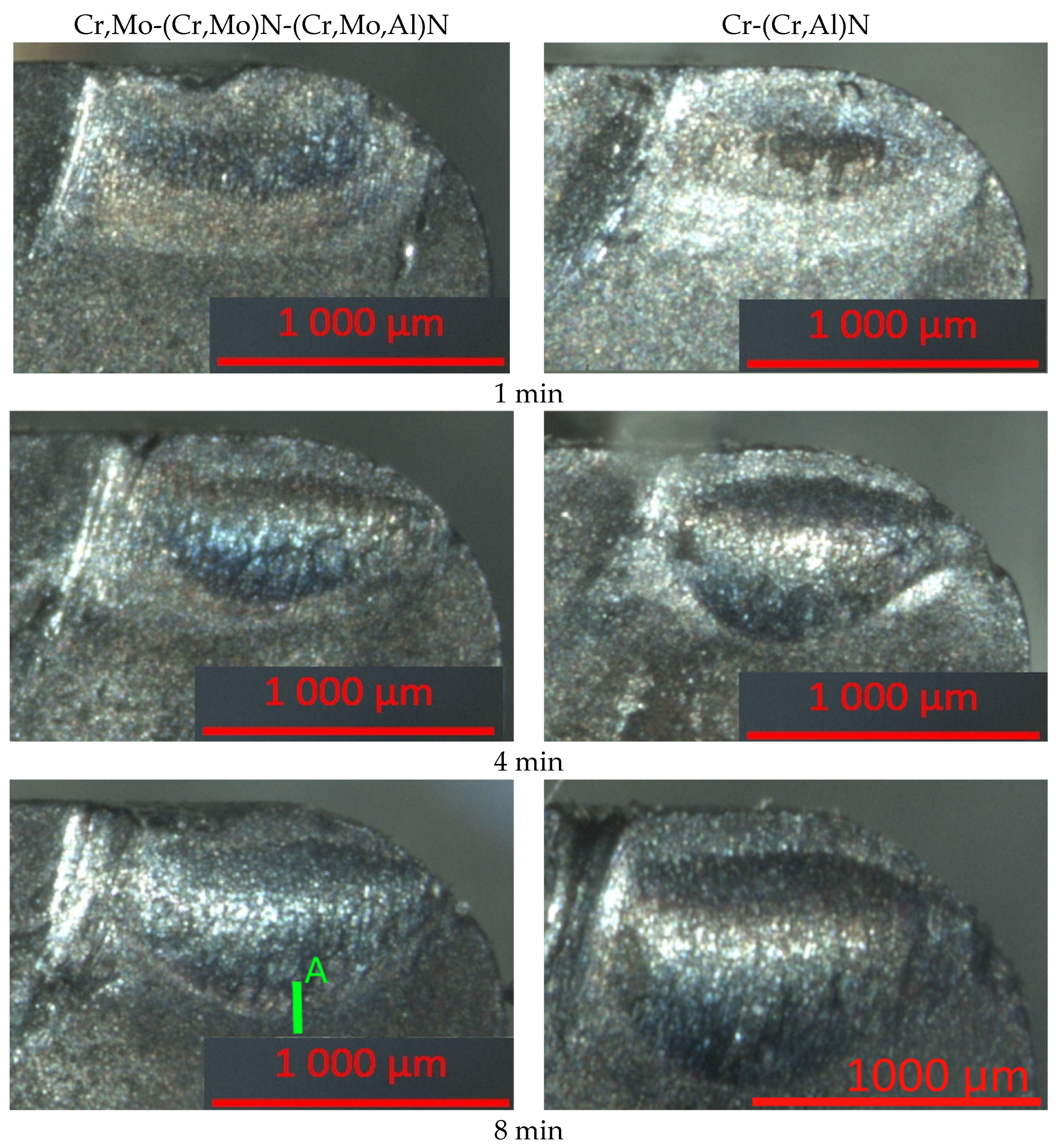
  • For the coating based on the (Cr,Al)N system, more active growth of wear crater on the rake face is typical compared to the coating based on the (Cr,Mo,Al)N system.
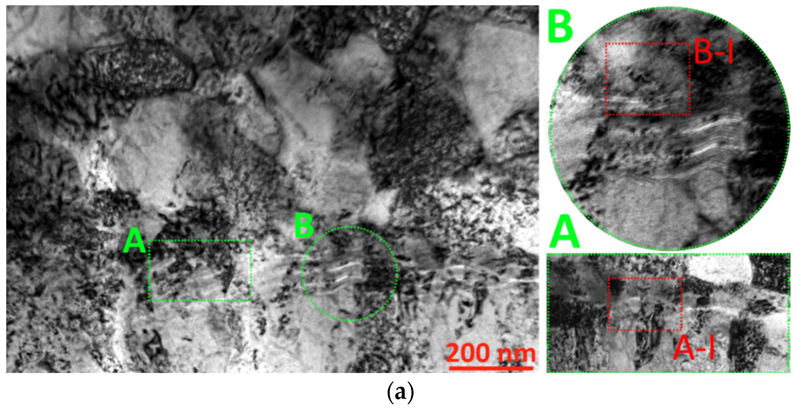
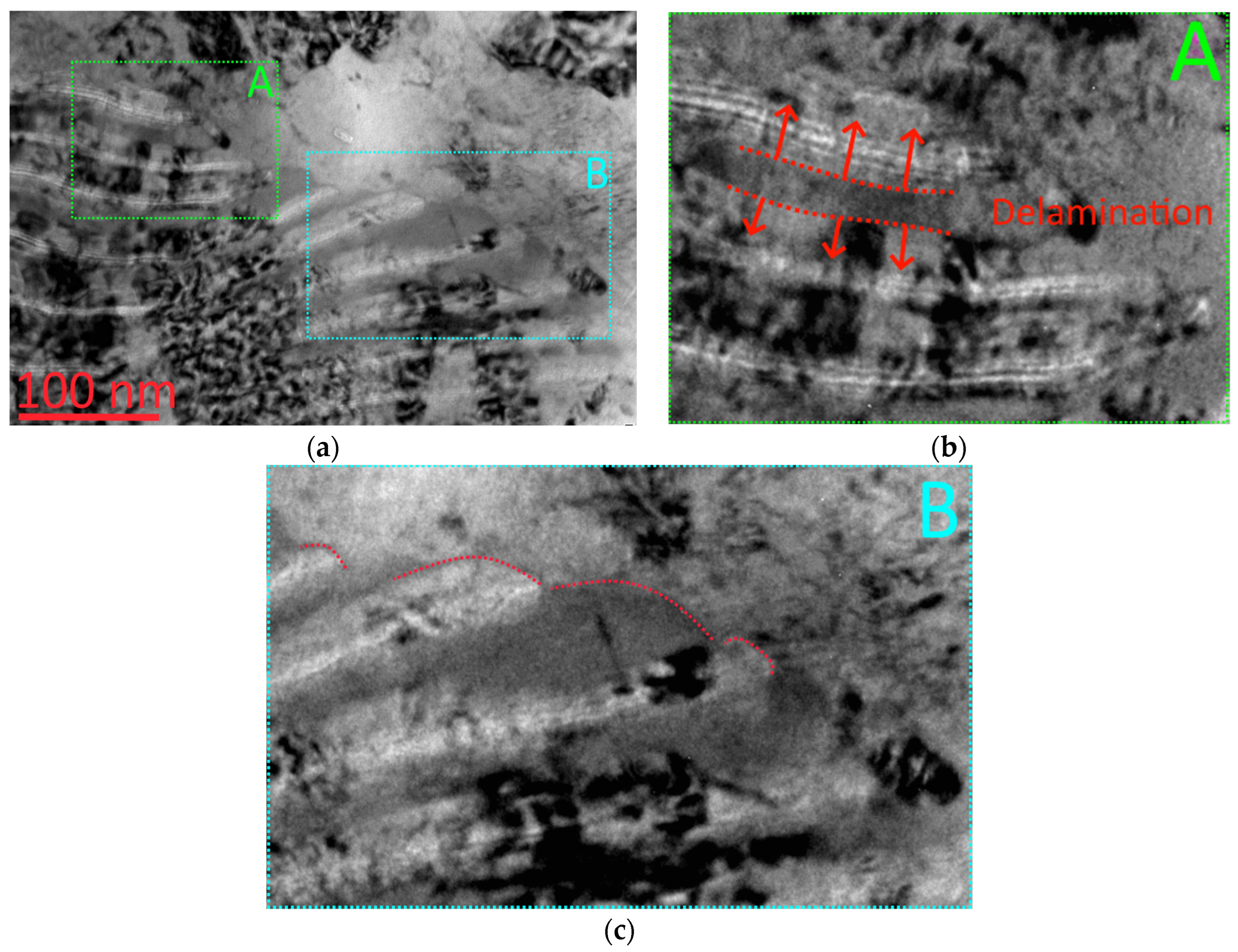
  • The analysis of the pattern of wear on the coating with nanolayer structure in contact with the cut material flow reveals the following fracture mechanisms:
  • Penetration of particles of the machined steel between nanolayers of the coating, resulting in interlayer delamination;
  • Plastic deformation (bending) of nanolayers of the coating under the influence of the moving flow of the machined steel;
  • Fracture of fragments from nanolayers of the coating with their further separation and removal by the cut material flow;
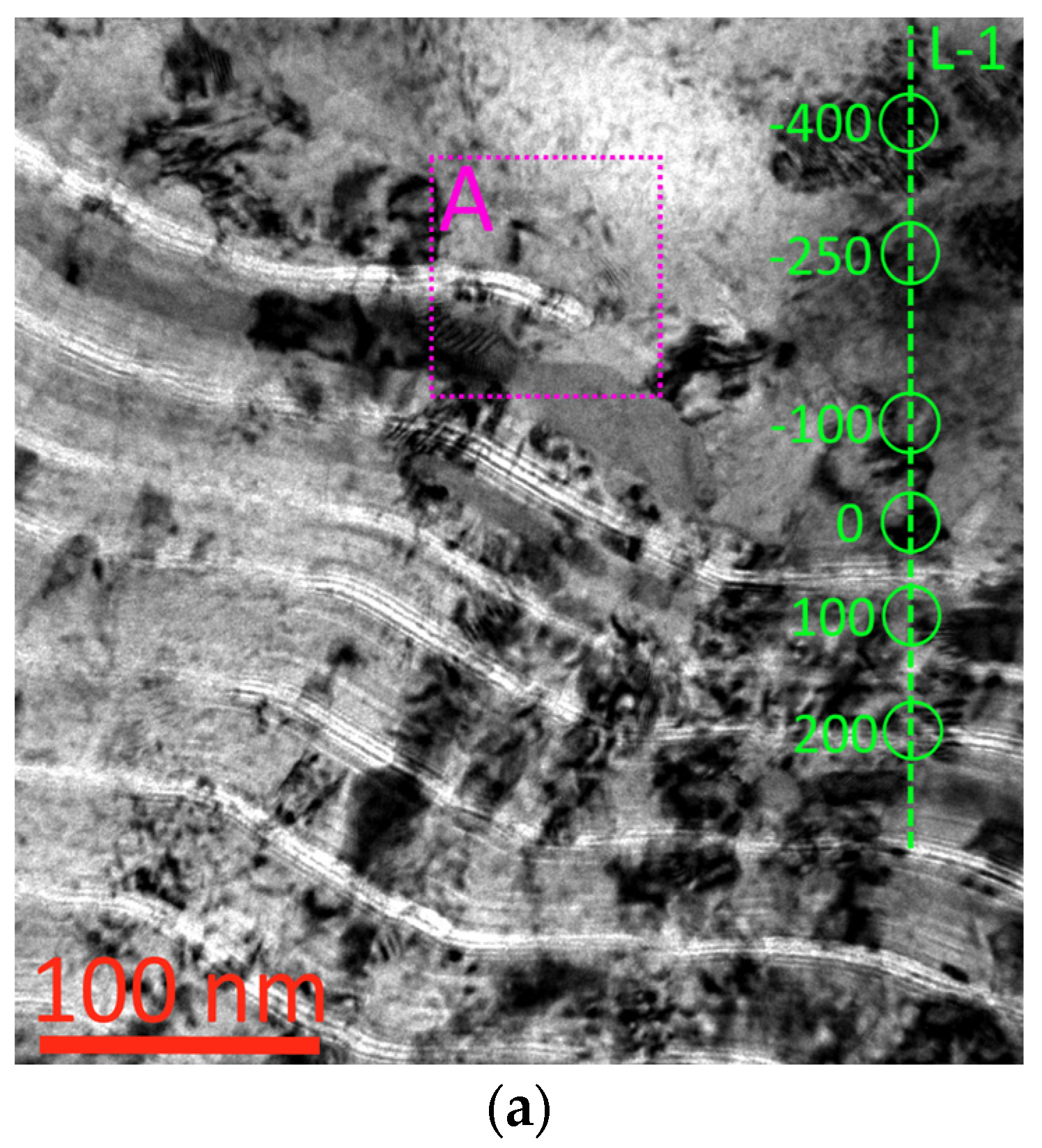
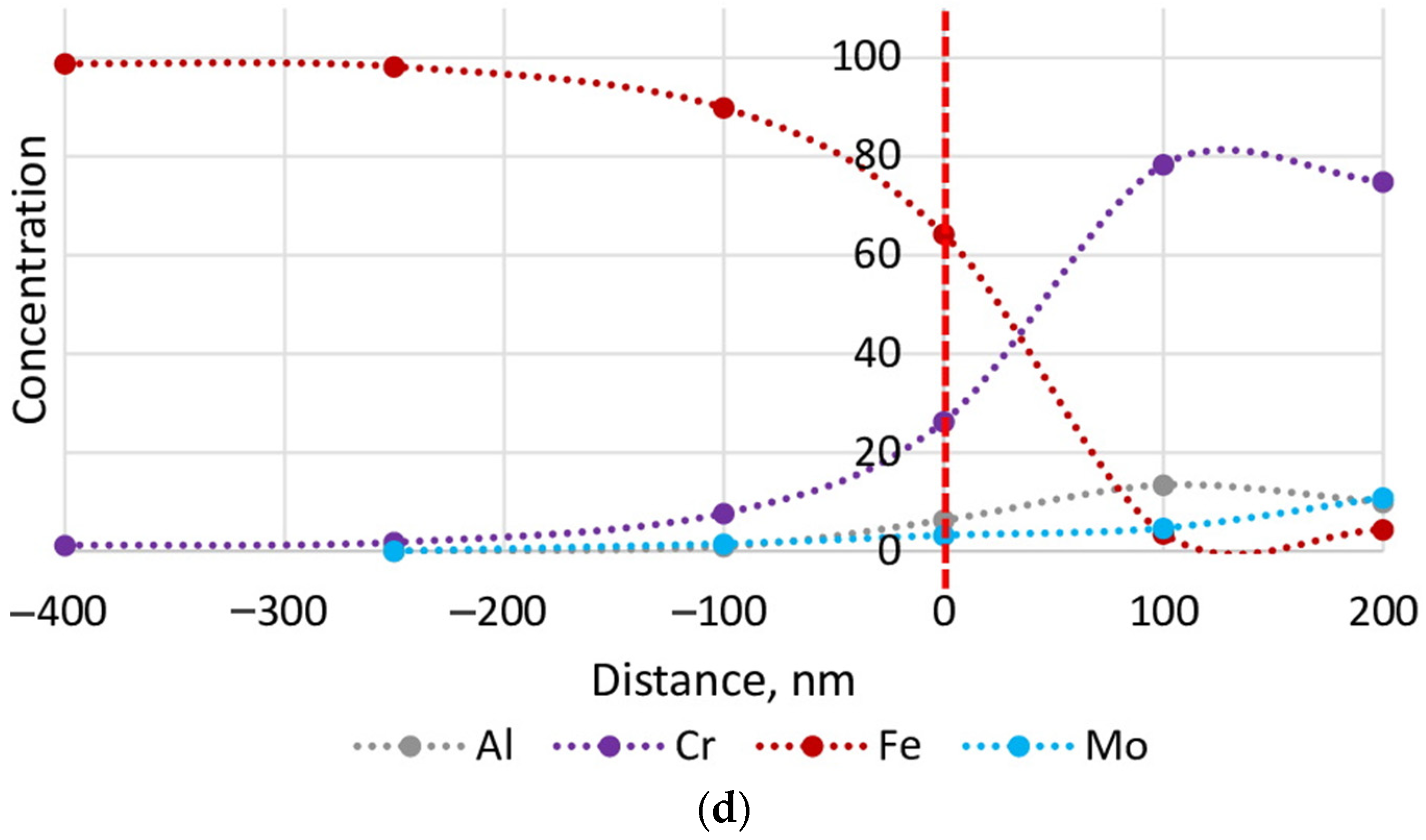
  • During the cutting, the diffusion of iron into the coating (to the depth not exceeding 200 nm) and the diffusion of coating elements (Cr and Mo) into the machined steel to the depth not exceeding 250 nm occur;
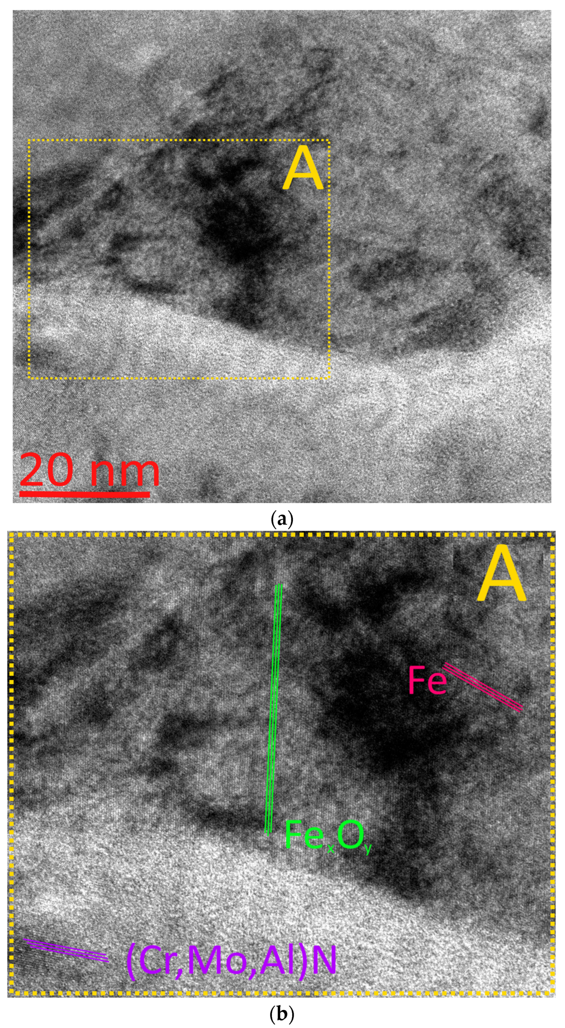
  • Along with the particles of iron on the “coating- machined steel” interface, the particles of iron oxides are detected with significantly higher hardness compared to iron, which can thereby more actively affect the wear of the coating.

Author Contributions

Conceptualization, A.V. and A.S.; methodology, A.V. and A.S.; writing—original draft preparation, A.V.; project administration, V.G. All authors have read and agreed to the published version of the manuscript.

Funding

This research was funded by Russian Science Foundation, grant number 20-79-00222.

Institutional Review Board Statement

Not applicable.

Informed Consent Statement

Not applicable.

Acknowledgments

The study used the equipment from the Centre for collective use of Moscow State Technological University STANKIN (agreement No. 075-15-2021-695, 26 July 2021). The coating structure was investigated using the equipment of the Centre for collective use of scientific equipment “Material Science and Metallurgy”, purchased with the financial support of the Ministry of Science and Higher Education of the Russian Federation (GK 075-15-2021-696).

Conflicts of Interest

The authors declare no conflict of interest.

References

  1. PalDey, S.; Deevi, S.C. Single layer and multilayer wear resistant coatings of (Ti, Al)N: A review. Mater. Sci. Eng. A 2003, 342, 58–79. [Google Scholar] [CrossRef]
  2. Bobzin, K. High-performance coatings for cutting tools CIRP. J. Manuf. Sci. Technol. 2017, 18, 1–9. [Google Scholar] [CrossRef]
  3. Ariharan, N.; Sriram, C.G.; Radhika, N.; Aswin, S.; Haridas, S. A comprehensive review of vapour deposited coatings for cutting tools: Properties and recent advances. Trans. Inst. Met. Finish. 2022, in press. [Google Scholar] [CrossRef]
  4. Klaus, M.; Genzel, C. Multilayer systems for cutting tools: On the relationship between coating design, surface processing, and residual stress. Adv. Eng. Mater. 2011, 13, 845–850. [Google Scholar] [CrossRef]
  5. Deng, Y.; Chen, W.; Li, B.; Wang, C.; Kuang, T.; Li, Y. Physical vapor deposition technology for coated cutting tools: A review. Ceram. Int. 2020, 46, 18373–18390. [Google Scholar] [CrossRef]
  6. Kuzin, V.V.; Grigoriev, S.N.; Volosova, M.A. The role of the thermal factor in the wear mechanism of ceramic tools: Part 1. Macrolevel. J. Frict. Wear 2014, 35, 505–510. [Google Scholar] [CrossRef]
  7. Grigoriev, S.N.; Gurin, V.D.; Volosova, M.A.; Cherkasova, N.Y. Development of residual cutting tool life prediction algorithm by processing on CNC machine tool. Mater. Werkst. 2013, 44, 790–796. [Google Scholar] [CrossRef]
  8. Grigoriev, S.; Fominski, V.; Gnedovets, A.; Romanov, R. Experimental and numerical study of the chemical composition of WSex thin films obtained by pulsed laser deposition in vacuum and in a buffer gas atmosphere. Appl. Surf. Sci. 2012, 258, 7000–7007. [Google Scholar] [CrossRef]
  9. Fominski, V.Y.; Grigoriev, S.N.; Celis, J.P.; Romanov, R.I.; Oshurko, V.B. Structure and mechanical properties of W-Se-C/diamond-like carbon and W-Se/diamond-like carbon bi-layer coatings prepared by pulsed laser deposition. Thin Solid Film. 2012, 520, 6476–6483. [Google Scholar] [CrossRef]
  10. Grigoriev, S.; Vereschaka, A.; Milovich, F.; Sitnikov, N.; Andreev, N.; Bublikov, J.; Kutina, N. Investigation of the properties of the Cr,Mo-(Cr,Mo,Zr,Nb)N-(Cr,Mo,Zr,Nb,Al)N multilayer composite multicomponent coating with nanostructured wear-resistant layer. Wear 2021, 468–469, 203597. [Google Scholar] [CrossRef]
  11. Grigoriev, S.; Vereschaka, A.; Milovich, F.; Tabakov, V.; Sitnikov, N.; Andreev, N.; Sviridova, T.; Bublikov, J. Investigation of multicomponent nanolayer coatings based on nitrides of Cr, Mo, Zr, Nb, and Al. Surf. Coat. Technol. 2020, 401, 126258. [Google Scholar] [CrossRef]
  12. Vereschaka, A.; Grigoriev, S.; Milovich, F.; Sitnikov, N.; Migranov, M.; Andreev, N.; Bublikov, J.; Sotova, C. Investigation of tribological and functional properties of Cr,Mo-(Cr,Mo)N-(Cr,Mo,Al)N multilayer composite coating. Tribol. Int. 2021, 155, 106804. [Google Scholar] [CrossRef]
  13. Grigoriev, S.; Vereschaka, A.; Milovich, F.; Andreev, N.; Bublikov, J.; Sitnikov, N.; Sotova, C.; Kutina, N. Investigation of wear mechanisms of multilayer nanostructured wear-resistant coatings during turning of steel. Part 2: Diffusion, oxidation processes and cracking in Ti-TiN-(Ti,Cr,Mo,Al)N coating. Wear 2021, 486–487, 204096. [Google Scholar] [CrossRef]
  14. Mayrhofer, P.H.; Mitterer, C.; Hultman, L.; Clemens, H. Microstructural design of hard coatings. Prog. Mater. Sci. 2006, 51, 1032–1114. [Google Scholar] [CrossRef]
  15. Yamamoto, K.; Sato, T.; Takahara, K.; Hanaguri, K. Properties of (Ti,Cr,Al)N coatings with high Al content deposited by new plasma enhanced arc-cathode. Surf. Coat. Technol. 2003, 174–175, 620–626. [Google Scholar] [CrossRef]
  16. Vereschaka, A.; Tabakov, V.; Grigoriev, S.; Sitnikov, N.; Milovich, F.; Andreev, N.; Sotova, C.; Kutina, N. Investigation of the influence of the thickness of nanolayers in wear-resistant layers of Ti-TiN-(Ti,Cr,Al)N coating on destruction in the cutting and wear of carbide cutting tools. Surf. Coat. Technol. 2020, 385, 125402. [Google Scholar] [CrossRef]
  17. Vereschaka, A.; Milovich, F.; Migranov, M.; Andreev, N.; Alexandrov, I.; Muranov, A.; Mikhailov, M.; Tatarkanov, A. Investigation of the tribological and operational properties of (Mex,Moy,Al1−(x+y))N (Me–Ti, Zr or Cr) coatings. Tribol. Int. 2022, 165, 107305. [Google Scholar] [CrossRef]
  18. Fox-Rabinovich, G.S.; Yamomoto, K.; Veldhuis, S.C.; Kovalev, A.I.; Dosbaeva, G.K. Tribological adaptability of TiAlCrN PVD coatings under high performance dry machining conditions. Surf. Coat. Technol. 2005, 200, 1804–1813. [Google Scholar] [CrossRef]
  19. Mayrhofer, P.H.; Willmann, H.; Reiter, A.E. Structure and phase evolution of Cr-Al-N coatings during annealing. Surf. Coat. Technol. 2008, 202, 4935–4938. [Google Scholar] [CrossRef]
  20. Reiter, A.E.; Derflinger, V.H.; Hanselmann, B.; Bachmann, T.; Sartory, B. Investigation of the properties of Al1-xCrxN coatings prepared by cathodic arc evaporation. Surf. Coat. Technol. 2005, 200, 2114–2122. [Google Scholar] [CrossRef]
  21. Wistrela, E.; Schmied, I.; Schneider, M.; Gillinger, M.; Mayrhofer, P.M.; Bittner, A.; Schmid, U. Impact of sputter deposition parameters on the microstructural and piezoelectric properties of CrxAl1−xN thin films. Thin Solid Film. 2018, 648, 76–82. [Google Scholar] [CrossRef]
  22. Bobzin, K.; Brögelmann, T.; Kruppe, N.C.; Engels, M. Correlation of the Debye sheath thickness and (Cr,Al)N coating properties for HPPMS, dcMS, CAE and PCAE processes. Surf. Coat. Technol. 2017, 332, 233–241. [Google Scholar] [CrossRef]
  23. Hu, C.; Xu, Y.X.; Chen, L.; Pei, F.; Zhang, L.J.; Du, Y. Structural, mechanical and thermal properties of CrAlNbN coatings. Surf. Coat. Technol. 2018, 349, 894–900. [Google Scholar] [CrossRef]
  24. Hu, C.; Chen, L.; Moraes, V. Structure, mechanical properties, thermal stability and oxidation resistance of arc evaporated CrAlBN coatings. Surf. Coat. Technol. 2021, 417, 127191. [Google Scholar] [CrossRef]
  25. Chen, Y.; Zhang, Z.; Yuan, T.; Mei, F.; Lin, X.; Gao, J.; Chen, W.; Xu, Y. The synergy of V and Si on the microstructure, tribological and oxidation properties of AlCrN based coatings. Surf. Coat. Technol. 2021, 412, 127082. [Google Scholar] [CrossRef]
  26. Wang, R.; Mei, H.; Li, R.; Zhang, T.; Wang, Q. Influence of V addition on the microstructure, mechanical, oxidation and tribological properties of AlCrSiN coatings. Surf. Coat. Technol. 2021, 407, 126767. [Google Scholar] [CrossRef]
  27. Hu, C.; Xu, Y.X.; Chen, L.; Pei, F.; Du, Y. Mechanical properties, thermal stability and oxidation resistance of Ta-doped CrAlN coatings. Surf. Coat. Technol. 2019, 368, 25–32. [Google Scholar] [CrossRef]
  28. Miyake, T.; Kishimoto, A.; Hasegawa, H. Tribological properties and oxidation resistance of (Cr,Al,Y)N and (Cr,Al,Si)N films synthesized by radio-frequency magnetron sputtering method. Surf. Coat. Technol. 2010, 205 (Suppl. 1), S290–S294. [Google Scholar] [CrossRef]
  29. Zhao, Y.; Feng, K.; Yao, C.; Li, Z. Effect of MoO3 on the microstructure and tribological properties of laser-clad Ni60/nanoCu/h-BN/MoO3 composite coatings over wide temperature range. Surf. Coat. Technol. 2020, 387, 125477. [Google Scholar] [CrossRef]
  30. Tao, H.; Tsai, M.T.; Chen, H.W.; Huang, J.C.; Duh, J.G. Improving high-temperature tribological characteristics on nanocomposite CrAlSiN coating by Mo doping. Surf. Coat. Technol. 2018, 349, 752–756. [Google Scholar] [CrossRef]
  31. Lu, Y.C.; Chen, H.W.; Chang, C.C.; Wu, C.Y.; Duh, J.G. Tribological properties of nanocomposite Cr-Mo-Si-N coatings at elevated temperature through silicon content modification. Surf. Coat. Technol. 2018, 338, 69–74. [Google Scholar] [CrossRef]
  32. Li, F.; Zhu, S.; Cheng, J.; Qiao, Z.; Yang, J. Tribological properties of Mo and CaF2 added SiC matrix composites at elevated temperatures. Tribol. Int. 2017, 111, 46–51. [Google Scholar] [CrossRef]
  33. Qi, D.; Chen, J.; Liu, J.; Lv, W.; Song, J.; Shen, L. Influence of Molybdenum Addition on Oxidation Resistance of CrN Coatings. Rare Metal Mater. Eng. 2021, 50, 1505–1512. [Google Scholar]
  34. Qi, D.; Lei, H.; Fan, D.; Pei, Z.; Gong, J.; Sun, C. Effect of Mo content on the microstructure and properties of CrMoN composite coatings. Acta Metall. Sin. 2015, 51, 371–377. [Google Scholar]
  35. Wang, Y.; Tang, Y.; Wan, W.; Zhang, X. High-Temperature Oxidation Resistance of CrMoN Films. J. Mater. Eng. Perform. 2020, 29, 6412–6416. [Google Scholar] [CrossRef]
  36. Amaya-Roncancio, S.; Arias-Mateus, D.F.; Gómez-Hermida, M.M.; Riaño-Rojas, J.C.; Restrepo-Parra, E. Molecular dynamics simulations of the temperature effect in the hardness on Cr and CrN films. Appl. Surf. Sci. 2012, 258, 4473–4477. [Google Scholar] [CrossRef]
  37. Cai, Z.; Zhang, P.; Di, Y. Microstructure, hardness and oxidation resistance of CrN and CrAlN coatings synthesized by multi-arc ion plating technology. Adv. Mater. Res. 2011, 168–170, 2430–2433. [Google Scholar] [CrossRef]
  38. Zeilinger, A.; Daniel, R.; Schöberl, T.; Stefenelli, M.; Sartory, B.; Keckes, J.; Mitterer, C. Resolving depth evolution of microstructure and hardness in sputtered CrN film. Thin Solid Film. 2015, 581, 75–79. [Google Scholar] [CrossRef]
  39. Ichimura, H.; Ando, I. Mechanical properties of arc-evaporated CrN coatings: Part I—Nanoindentation hardness and elastic modulus. Surf. Coat. Technol. 2001, 145, 88–93. [Google Scholar] [CrossRef]
  40. Tian, C.X.; Han, B.; Zou, C.W.; Xie, X.; Li, S.Q.; Liang, F.; Tang, X.S.; Wang, Z.S.; Pelenovich, V.O.; Zeng, X.M.; et al. Synthesis of monolayer MoNx and nanomultilayer CrN/Mo2N coatings using arc ion plating. Surf. Coat. Technol. 2019, 370, 125–129. [Google Scholar] [CrossRef]
  41. Shirazi, M.; Ghasemloo, M.; Etaati, G.R.; Hosseinnejad, M.T.; Toroghinejad, M.R. Plasma focus method for growth of molybdenum nitride thin films: Synthesis and thin film characterization. J. Alloys Compd. 2017, 727, 978–985. [Google Scholar] [CrossRef]
  42. Wang, J.; Munroe, P.; Zhou, Z.; Xie, Z. Nanostructured molybdenum nitride-based coatings: Effect of nitrogen concentration on microstructure and mechanical properties. Thin Solid Film. 2019, 682, 82–92. [Google Scholar] [CrossRef]
  43. Wang, T.; Zhang, G.; Ren, S.; Jiang, B. Effect of nitrogen flow rate on structure and properties of MoNx coatings deposited by facing target sputtering. J. Alloys Compd. 2017, 701, 1–8. [Google Scholar] [CrossRef]
  44. Klimashin, F.; Koutná, N.; Euchner, H.; Holec, D.; Mayrhofer, P. The impact of nitrogen content and vacancies on structure and mechanical properties of Mo–N thin films. J. Appl. Phys. 2016, 120, 185301. [Google Scholar] [CrossRef] [Green Version]
  45. Vetter, J.; Eriksson, A.O.; Reiter, A.; Derflinger, V.; Kalss, W. Quo vadis: Alcr-based coatings in industrial applications. Coatings 2021, 11, 344. [Google Scholar] [CrossRef]
  46. Yoon, C.S.; Kim, K.H.; Kwon, S.H.; Park, I.W. Syntheses and properties of Cr-Al-Mo-N coatings fabricated by using a hybrid coating system. J. Korean Phys. Soc. 2009, 54, 1237–1241. [Google Scholar] [CrossRef]
  47. Klimashin, F.F.; Mayrhofer, P.H. Ab initio-guided development of super-hard Mo-Al-Cr-N coatings. Scr. Mater. 2017, 140, 27–30. [Google Scholar] [CrossRef]
  48. Bobzin, K.; Brögelmann, T.; Kalscheuer, C.; Stahl, K.; Lohner, T.; Yilmaz, M. Effects of (Cr,Al)N and (Cr,Al,Mo)N coatings on friction under minimum quantity lubrication. Surf. Coat. Technol. 2020, 402, 126154. [Google Scholar] [CrossRef]
  49. Wang, Y.; Lou, B. Microstructure and High-Temperature Friction and Wear Properties of CrAlMoN Film. Oxid. Met. 2021, 95, 239–250. [Google Scholar] [CrossRef]
  50. Iram, S.; Cai, F.; Wang, J.; Zhang, J.; Liang, J.; Ahmad, F.; Zhang, S. Effect of addition of Mo or V on the structure and cutting performance of AlCrN-based coatings. Coatings 2020, 10, 298. [Google Scholar] [CrossRef] [Green Version]
  51. Bobzin, K.; Brögelmann, T.; Kalscheuer, C. Arc PVD (Cr,Al,Mo)N and (Cr,Al,Cu)N coatings for mobility applications. Surf. Coat. Technol. 2020, 384, 125046. [Google Scholar] [CrossRef]
  52. Iram, S.; Wang, J.; Cai, F.; Zhang, J.; Ahmad, F.; Liang, J.; Zhang, S. Effect of bilayer number on mechanical and wear behaviours of the AlCrN/AlCrMoN coatings by AIP method. Surf. Eng. 2021, 37, 536–544. [Google Scholar] [CrossRef]
  53. Grigoriev, S.; Vereschaka, A.; Milovich, F.; Sitnikov, N.; Andreev, N.; Bublikov, J.; Sotova, C.; Oganian, G.; Sadov, I. Investigation of the properties of Ti-TiN-(Ti,Cr,Mo,Al)N multilayered composite coating with wear-resistant layer of nanolayer structure. Coatings 2020, 10, 1236. [Google Scholar] [CrossRef]
  54. Vereshchaka, A.A.; Vereshchaka, A.S.; Mgaloblishvili, O.; Morgan, M.N.; Batako, A.D. Nano-scale multilayered-composite coatings for the cutting tools. Int. J. Adv. Manuf. Technol. 2014, 72, 303–317. [Google Scholar] [CrossRef]
  55. Vereschaka, A.; Tabakov, V.; Grigoriev, S.; Aksenenko, A.; Sitnikov, N.; Oganyan, G.; Seleznev, A.; Shevchenko, S. Effect of adhesion and the wear-resistant layer thickness ratio on mechanical and performance properties of ZrN-(Zr,Al,Si)N coatings. Surf. Coat. Technol. 2019, 357, 218–234. [Google Scholar] [CrossRef]
  56. Metel, A.S.; Grigoriev, S.N.; Melnik, Y.A.; Bolbukov, V.P. Characteristics of a fast neutral atom source with electrons injected into the source through its emissive grid from the vacuum chamber. Instrum. Exp. Tech. 2012, 55, 288–293. [Google Scholar] [CrossRef]
  57. Metel, A.; Grigoriev, S.; Melnik, Y.; Panin, V.; Prudnikov, V. Cutting Tools Nitriding in Plasma Produced by a Fast Neutral Molecule Beam. Jpn. J. Appl. Phys. 2011, 50, 08JG04. [Google Scholar] [CrossRef]
  58. Metel, A.S.; Grigoriev, S.N.; Melnik, Y.A.; Bolbukov, V.P. Broad beam sources of fast molecules with segmented cold cathodes and emissive grids. Instrum. Exp. Tech. 2012, 55, 122–130. [Google Scholar] [CrossRef]
  59. Grigoriev, S.N.; Metel, A.S.; Fedorov, S.V. Modification of the structure and properties of high-speed steel by combined vacuum-plasma treatment. Met. Sci. Heat Treat. 2012, 54, 8–12. [Google Scholar] [CrossRef]
  60. Fominski, V.Y.; Grigoriev, S.N.; Gnedovets, A.G.; Romanov, R.I. Pulsed laser deposition of composite Mo–Se–Ni–C coatings using standard and shadow mask configuration. Surf. Coat. Technol. 2012, 206, 5046–5054. [Google Scholar] [CrossRef]
  61. Grigoriev, S.N.; Melnik, Y.A.; Metel, A.S.; Panin, V.V.; Prudnikov, V.V. A compact vapor source of conductive target material sputtered by 3-keV ions at 0.05-Pa pressure. Instrum. Exp. Tech. 2009, 52, 731–737. [Google Scholar] [CrossRef]
  62. Grigoriev, S.; Vereschaka, A.; Zelenkov, V.; Sitnikov, N.; Bublikov, J.; Milovich, F.; Andreev, N.; Mustafaev, E. Specific features of the structure and properties of arc-PVD coatings depending on the spatial arrangement of the sample in the chamber. Vacuum 2022, 200, 111047. [Google Scholar] [CrossRef]
  63. Oliver, W.C.; Pharr, G.M.J. An improved technique for determining hardness and elastic modulus using load and displacement sensing indentation. J. Mater. Res. 1992, 7, 1564–1583. [Google Scholar] [CrossRef]
  64. ASTM C1624-05(2015); Standard Test Method for Adhesion Strength and Mechanical Failure Modes of Ceramic Coatings by Quantitative Single Point Scratch Testing. ASTM International: West Conshohocken, PA, USA, 2010. [CrossRef]
  65. Grigoriev, S.; Vereschaka, A.; Zelenkov, V.; Sitnikov, N.; Bublikov, J.; Milovich, F.; Andreev, N.; Sotova, C. Investigation of the influence of the features of the deposition process on the structural features of microparticles in PVD coatings. Vacuum 2022, 202, 111144. [Google Scholar] [CrossRef]
  66. Mohamed, Y.S.; El-Gamal, H.; Zaghloul, M.M.Y. Micro-hardness behavior of fiber reinforced thermosetting composites embedded with cellulose nanocrystals. Alex. Eng. J. 2018, 57, 4113–4119. [Google Scholar] [CrossRef]
  67. Zaghloul, M.M.Y.; Zaghloul, M.Y.M.; Zaghloul, M.M.Y. Experimental and modeling analysis of mechanical-electrical behaviors of polypropylene composites filled with graphite and MWCNT fillers. Polym. Test. 2017, 63, 467–474. [Google Scholar] [CrossRef]
  68. Zaghloul, M.M.Y.; Steel, K.; Veidt, M.; Heitzmann, M.T. Wear behaviour of polymeric materials reinforced with man-made fibres: A comprehensive review about fibre volume fraction influence on wear performance. J. Reinf. Plast. Compos. 2022, 41, 215–241. [Google Scholar] [CrossRef]
  69. Mahmoud Zaghloul, M.Y.; Yousry Zaghloul, M.M.; Yousry Zaghloul, M.M. Developments in polyester composite materials—An in-depth review on natural fibres and nano fillers. Compos. Struct. 2021, 278, 114698. [Google Scholar] [CrossRef]
  70. Zaghloul, M.M.Y.M. Mechanical properties of linear low-density polyethylene fire-retarded with melamine polyphosphate. J. Appl. Polym. Sci. 2018, 135, 46770. [Google Scholar] [CrossRef]
  71. Zaghloul, M.M.Y.; Zaghloul, M.M.Y. Influence of flame retardant magnesium hydroxide on the mechanical properties of high density polyethylene composites. J. Reinf. Plast. Compos. 2017, 36, 1802–1816. [Google Scholar] [CrossRef]
  72. Varga, G.; Ferencsik, V. Analysis of Cylindricity Error of High and Low Temperature Storage Tested Alternator Stators. Int. J. Automot. Technol. 2020, 21, 1519–1526. [Google Scholar] [CrossRef]
  73. Kundrák, J.; Pálmai, Z.; Varga, G. Analysis of Tool Life Functions in Hard Turning. Teh. Vjesn. 2020, 27, 166–173. [Google Scholar]
  74. Karpuschewski, B.; Kundrák, J.; Felhő, C.; Varga, G.; Borysenko, D. Effects of the tool edge design on the roughness of face milled surfaces. Iop Conf. Ser. Mater. Sci. Eng. 2018, 448, 012056. [Google Scholar] [CrossRef]
  75. Astakhov, V.P. Tribology of Cutting Tools, Chapter 1. In Tribology in Manufacturing Technology; Springer: Dordrecht, The Netherlands, 2013; pp. 1–66. [Google Scholar]
  76. Gates, J.D. Two-body and three-body abrasion: A critical discussion. Wear 1998, 214, 139–146. [Google Scholar] [CrossRef]
  77. Moore, M.A. Abrasive wear. Mater. Eng. Appl. 1978, 1, 97–111. [Google Scholar] [CrossRef]
  78. Torrance, A.A. An explanation of the hardness differential needed for abrasion. Wear 1981, 68, 263–266. [Google Scholar] [CrossRef]
  79. Coronado, J.J.; Rodríguez, S.A.; Sinatora, A. Effect of particle hardness on mild-severe wear transition of hard second phase materials. Wear 2013, 301, 82–88. [Google Scholar] [CrossRef]
Figure 1. (a) Diffraction patterns, (b) selected area electron diffraction (SAED) pattern, (c) micro- and nanostructure of the Cr,Mo-(Cr,Mo)N-(Cr,Mo,Al)N coating.
Coatings 12 00758 g001
Figure 2. Investigation of tool wear during the turning. (a) flank face wear, (b) rake face wear.
Coatings 12 00758 g002
Figure 3. Wear dynamics on the rake face of carbide inserts with the Cr,Mo-(Cr,Mo)N-(Cr,Mo,Al)N coating and the reference coating of Cr-(Cr,Al)N. Localization of lamella A.
Coatings 12 00758 g003
Figure 4. Deformation in the structure of nanolayers of the Cr,Mo-(Cr,Mo)N-(Cr,Mo,Al)N coating under the influence of the cut material flow. (a) General view of the investigated coverage area; (b) Deformation of the outer layers of the coating under the influence of a moving layer of the cut material; (c) Deformation of coating nanolayers under the influence of grains of cut material introduced into the structure.
Coatings 12 00758 g004aCoatings 12 00758 g004b
Figure 5. (a) Specifics of the interaction between the cut material flow and the structure of coating nanolayers, (bd) penetration of grains of the machined steel into the structure of the coating.
Coatings 12 00758 g005
Figure 6. (a,b) Penetration of a fragment of the machined steel into the structure of the coating, (c) Fourier analysis of the area of the “coating-machined steel” interface, (d) study of the diffusion processes on the area of the “coating-machined steel” interface (line L1).
Coatings 12 00758 g006aCoatings 12 00758 g006bCoatings 12 00758 g006c
Figure 7. (ac) Effect of the cut material flow on the nanolayer structure of the coating.
Coatings 12 00758 g007
Figure 8. Study of the crystal structure of the area on the boundary between the contact of the cut material layer and the coating. (a) General view of the studied coverage area; (b) Identification of grains: iron, iron oxide and cubic structure of the coating.
Coatings 12 00758 g008
Table 1. The conditions of the coating deposition.
Gas Pressure
pN (Pa)
Voltage on Substrate U (V)Cathode Arc Current (A)
AlCr-MoCr
Heating and subsequent cleaning of samples with gas plasma2.0100 DC7511075
Coating deposition0.42−150 DC16011075
Product cooling0.06----
Publisher’s Note: MDPI stays neutral with regard to jurisdictional claims in published maps and institutional affiliations.

