Article

A High-Efficiency Technology for Manufacturing Aircraft Carbon Brake Discs with Stable Friction Performance

1
School of Materials and Chemical Engineering, Xi’an Technological University, Xi’an 710021, China
2
Xi’an Chaoma Technology Co., Ltd., Xi’an 710025, China
3
Xi’an Aerospace Composites Research Institute, Xi’an 710025, China
4
Representative Office in Datong of PLA, Datong 037036, China
*
Authors to whom correspondence should be addressed.
Coatings 2022, 12(6), 768; https://doi.org/10.3390/coatings12060768
Submission received: 8 May 2022 / Revised: 31 May 2022 / Accepted: 1 June 2022 / Published: 3 June 2022
(This article belongs to the Special Issue Structural, Mechanical and Tribological Properties of Hard Coatings)

Abstract

:
A binary C/C brake disc (i.e., the test brake disc) was prepared with a C/C (pyrolytic carbon/resin carbon) matrix using modified natural gas as the carbon source through the isothermal chemical vapor infiltration (ICVI) process with a directed flow and the pressure impregnation carbonization (PIC) process with liquid-phase furfural acetone resin. The microstructural, mechanical, thermal, friction and wear properties of the test brake disc were comprehensively analyzed and compared with commercial ones. The results showed that the production efficiency of the test brake disc was 36% higher than that of the commercial ones, which were manufactured through a thermal-gradient chemical vapor infiltration (TCVI) process. The favorable mechanical and thermal properties of the test brake disc were comparable to the commercial ones. While the test brake disc had a more consistently rough laminar microstructure on the worn surface of the brake disc than the commercial ones, this avoided the annular grinding grooves on the worn surface after the braking tests. In addition, the test brake disc had a stable friction coefficient with a low dispersion coefficient of 3.90%, which would improve the friction stability of C/C brake discs used in aircrafts.

1. Introduction

Carbon/carbon (C/C) composites are pure-carbon multiphase structures with carbon fiber or fabric as the reinforcement phase, pyrolytic carbon obtained with chemical vapor infiltration (CVI), resin or asphalt carbon obtained from liquid-phase impregnation carbonization as the matrix. C/C composites have attracted extensive attention from the global military industry due to the fact of their unique structural and functional properties. Since the 1960s, developed countries have been competing regarding the development of C/C composite material [1,2]. The US and France have initiated a series of programs developing C/C composite-based applications, including the Launch Vehicle Materials Program and the Program for Finding Opportunities for Carbon–Carbon Nozzles, using C/C composites first in critical components such as the nose cones of strategic missiles, the nozzle throat linings and the expanding segments of solid rocket motors. In addition, C/C composites have good friction properties, long service lives, and high heat absorption capacities, which make these composites the most advanced materials for aircraft brake discs, accounting for more than 90% of the world’s total output of C/C composites. Carbon brake discs have been widely used in various types of aircraft [3,4,5].
Chinese corporations began researching C/C brakes for civil aircraft in the mid-1980s. As of 2022, several Chinese companies, including Xi’an Chaoma Technology Co., Ltd.; Hunan Boyun New Materials Co., Ltd.; Huaxing Aviation Aircraft Wheel Co., Ltd.; Beijing Institute of Aeronautical Materials; Beijing Bei Mo Gao Ke Friction Material Co., Ltd.; Shaanxi Lantai Aviation Equipment Co., Ltd.; have obtained airworthiness certifications for use on a number of aircrafts such as the Boeing 757 and 767; the Airbus A319/A320, A321, and A330; the Modern Ark 60 and 600; the COMAC C919. At present, there are two major technical routes for Chinese-made aircraft brakes. One is the binary mix carbon matrix technical route using the thermal gradient method with propylene as the carbon source, as used by Xi’an Chaoma Technology Co., Ltd., and Hunan Boyun New Materials Co., Ltd. The other is the pure pyrolytic–carbon matrix technical route using an isothermal method with natural gas as the carbon source as used by Huaxing Aviation Aircraft Wheel Co., Ltd. The first method has the disadvantages of long manufacturing times, high manufacturing costs and large brake vibrations, whereas the second method has the disadvantages of low coefficients of friction, short service lives, long manufacturing times and high costs. As of 2022, European and American manufacturers, by virtue of their low-price sales models of mainstream aircrafts, still have a market share of more than 90% of the C/C brake discs used in Chinese civil aircrafts [6,7].
There are many factors affecting the friction and mechanical properties of C/C composites including the carbon fiber preform, densification process, high-temperature heat treatment, mechanical processing and the synergistic effect of these factors. After years of development, the performance of Chinese-made aircraft brake discs prepared by various methods is still deficient. As a braking material, the mechanical properties and frictional wear performance of the carbon materials are important indicators of brake discs. Carbon/carbon composites must have sufficient strength, including flexural, tensile, compressive, fracture toughness, and shear properties, to meet structural design requirements. The friction coefficient and wear amount are important parameters affecting the braking performance of carbon brake discs. By adjusting their composition, microstructure and densification process, carbon brake discs with excellent performance can be prepared [8,9]. The polarized structure of matrix pyrolytic carbon is the brake disc’s main influencing factor. For pyrolytic carbon, it is generally divided into a rough layer, smooth layer and isotropic structure according to the extinction angle and polarization structure, among which the rough-layer pyrolytic carbon will form a uniform and dense friction layer on the friction surface during the braking process to meet the requirements of different braking conditions of the aircraft [10]. The preparation methods for carbon/carbon aircraft brake disc matrix carbon include pyrolytic carbon obtained by chemical vapor deposition and resin carbon obtained by liquid-phase impregnation. The porosity of the brake discs obtained using the resin-impregnated carbon method is so high that their mechanical properties and wet state brake performance are poor. Compared with the resin-impregnated carbon method, the matrix carbon obtained by the chemical vapor-phase infiltration method has denser structures and is widely used in the production of carbon/carbon brake discs. Chemical vapor permeation methods mainly include the homogeneous temperature method, the temperature gradient method and the pressure difference method. The temperature gradient method can improve the deposition rate, while the temperature difference will cause an uneven distribution of the pyrolytic carbon between the inner and outer rings and poor friction stability, etc. The disadvantage of the pressure difference method is that it facilitates the formation of carbon black on the product surface, resulting in an uneven radial density of the product, which is not suitable for industrial production [11,12,13,14,15]. Therefore, the current Chinese-made carbon brake discs generally have the problems of uneven chemical vapor-phase penetration, rough-layer pyrolytic carbon distribution and an unstable friction coefficient as well as long production preparation cycles and high production costs [16,17].
In order to overcome the shortcomings of the technologies described above, including improving the density and structural homogeneity of carbon/carbon composites, maintaining the brake disc products with good friction and vibration properties, shortening the production cycles, reducing the costs and further improving the market competitiveness of Chinese-made C/C aircraft brake discs, the preparation of aircraft carbon brake discs with stable friction coefficients and high efficiency was carried out and compared with commercial discs. The production efficiency and cost, microstructure and mechanical, thermal, frictional and wear properties of three different C/C brake discs for the same aircraft model were investigated: the binary C/C brake disc manufactured, with natural gas as the carbon source (referred to as the test brake disc); the binary C/C brake disc manufactured using the thermal gradient method, with propylene as the carbon source (referred to as commercial brake disc 1); the carbon brake disc manufactured using the CVI method (referred to as commercial brake disc 2) [18,19].

2. Materials and Methods

2.1. Manufacturing of the Test Brake

The preforms were manufactured by laminating and needle-punching alternative layers of unidirectional carbon fiber textile and felt, produced by the Yixing Tianniao Company (Wuxi, China). The preform had an initial density of 0.58–0.62 g/cm3. After pretreatment at high temperatures, ranging from 1800 to 2100 °C, the preform was densified in an induction CVI reactor using modified natural gas as a gaseous precursor for three cycles totaling 384 h. The preform was further densified using resin pressure impregnation carbonization (PIC) for two cycles, and the density was 1.81 g/cm3. Then, the preform was graphitized and antioxidized at a temperature range from 2000 to 2300 °C, followed by machining, riveting and, finally, assembly to form the test brake disc [20,21]. The preparation processes of the test discs are shown in Figure 1.
The test brake disc was compared with commercial brake disc 1 and commercial brake disc 2.

2.2. Microstructural Characterization

The texture and extinction angle of the microstructure of the deposited pyrolytic carbon was examined using a polarized light microscope (Axioskop 40, Zeiss, Germany). The facture morphology of the C/C composite and the interfaces were characterized through scanning electron microscopy (SEM, JSM-6460LV, Japan Electronics Co., Ltd, Tokyo, Japan).

2.3. Physical Property Characterization

The lattice constant, d002, and the crystal size were determined through XRD (D8 X-ray diffractometer, Bruker Company, Billerica, MA, USA) according to QJ 2507-93. The degree of graphitization was calculated using the Franklin model and a simplified equation based on a 3 g powder sample [22]. The bulk density was measured according to JB/T 8133.14-2013.

2.4. Mechanical Property Characterization

The compressive, flexural and shear strengths of the specimens were measured using a DSS-10T-S electronic universal material tester (Instron 5966, Instron Instrument Company, Norwood, MA, USA) according to QJ 2305-92, QJ 2099-91 and Q/GB 97-92, with specimens measuring 20 mm × 20 mm × 20 mm, 80 mm × 10 mm × 6 mm and Φ50/Φ10.5 × 4 mm, respectively.

2.5. Thermal Property Characterization

The thermal diffusivity and specific heat capacity were measured using a laser thermophysical tester (TC-3000, Netzsch, Germany) according to the ISO 22007-2:2015 standard. The thermal conductivity was then calculated. The test was conducted on specimens measuring Φ12.7 × 3 mm at temperatures from room temperature to 800 °C.

2.6. Characterization of Friction and Wear Properties

The friction and wear properties of the carbon brake discs were tested using an HJDS-II aircraft tire/wheel brake assembly dynamic simulation tester at the Guilin Chemical Industry Special Tire Quality Inspection and Testing Center, which has been used to test the friction and wear properties of carbon brake discs in multiple models for different manufacturers. The dynamic simulation tester meets the ground test standard requirements of CAAC and FAA [23,24]. The test brake discs were subjected to 20 dynamic tests at a design landing energy of 28.22 MJ, one dynamic test at an overload landing energy of 37.8 MJ and one static torque test at a braking pressure of 20.7 MPa.
For comparison, the commercial brake disc 1 was subjected to 101 dynamic tests at the design landing energy, five dynamic tests at an overload landing energy and one static braking torque test. The commercial brake disc 2 was subjected to 62 dynamic tests at the design landing energy, six dynamics tests at an overload landing energy and one static braking torque test. Table 1 shows the parameters of the ground dynamic simulation tests.

3. Results

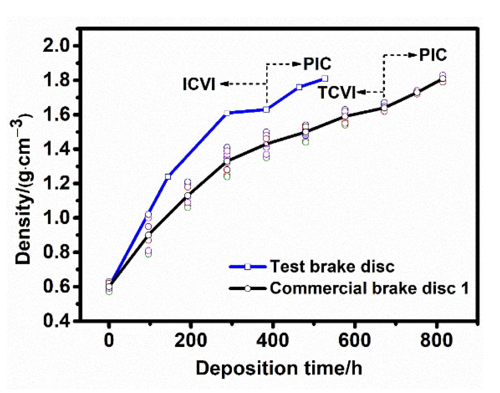
3.1. Densification Efficiency
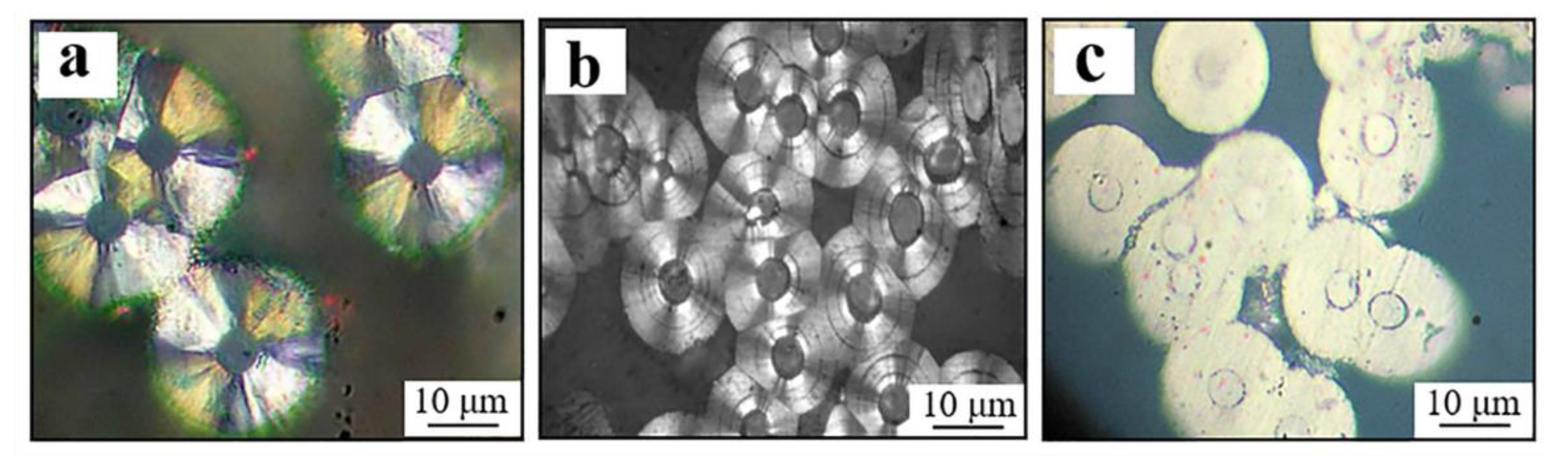
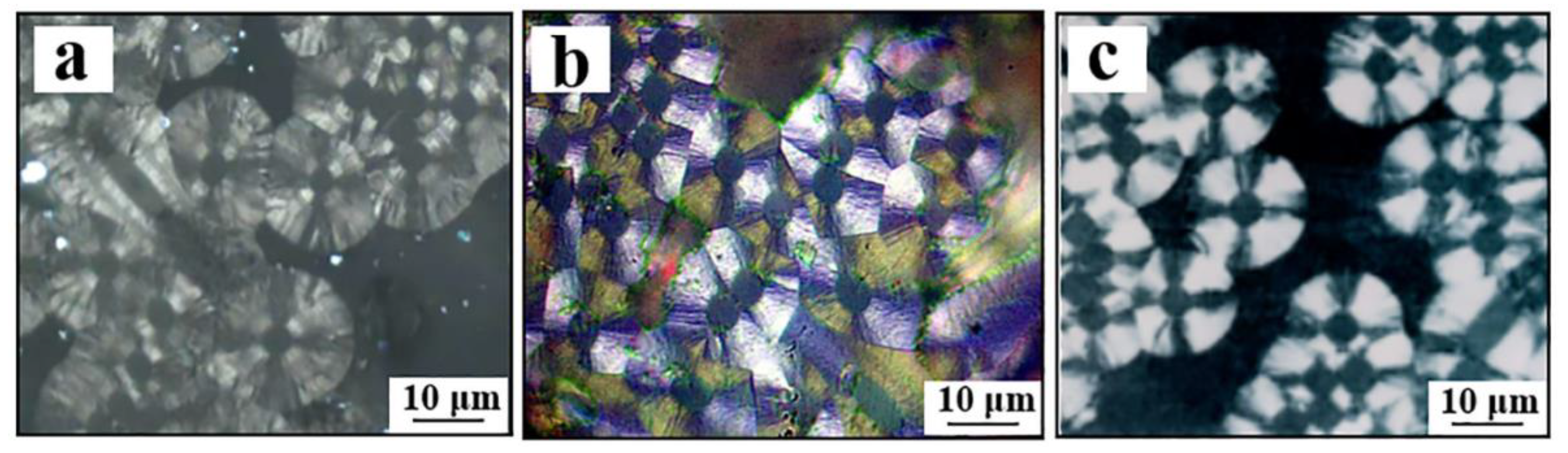
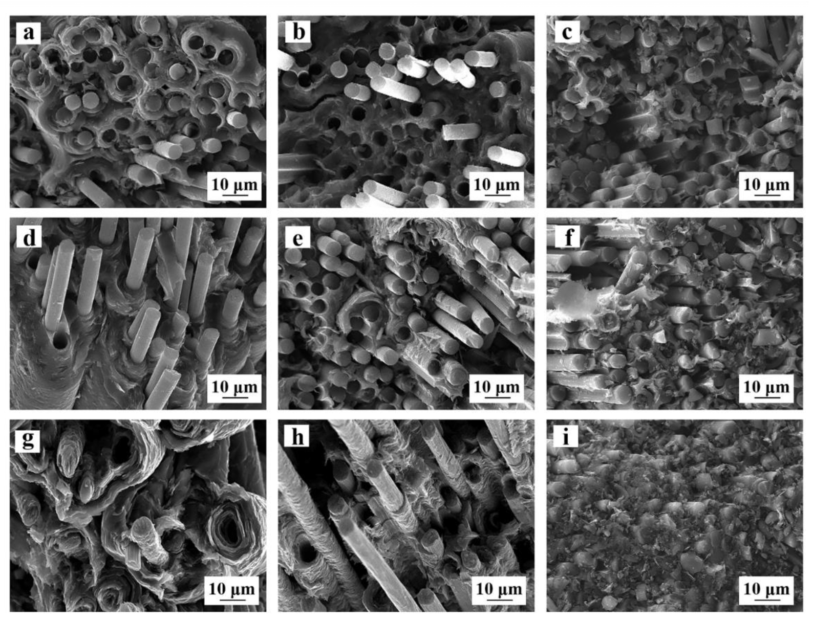
The test brake disc was densified using a natural gas formula and isothermal CVI (ICVI) in a 250 kW class induction CVI reactor for three cycles and for a total time of 384 h. The average density reached a mean value of 1.63 g/cm3. Commercial brake disc 1 was densified using propylene gas and a thermal gradient CVI (TCVI) process, which required an average time of 672 h to reach the same density of 1.63 g/cm3. The brake disc performances were densified to an average density of 1.81 g/cm3 after two cycles of PIC, and the density stabilized at 1.79 g/cm3 after a graphitization treatment. Regarding the test brake disc and commercial brake disc 1, their densities reached 1.63 g/cm3 after CVI, which satisfied the product density requirement after two cycles of PIC, with no obvious differences in the liquid densification efficiency.
Figure 2 shows the variation in the density over the deposition time for the test brake disc and the fitted curves for commercial brake disc 1. Figure 3 shows the variation in the densification rate with deposition time for the two brake discs, which were obtained by differentiating the data in Figure 2 through Origin software. With natural gas as the carbon source, the test brake disc reached densities of 1.24 and 1.61 g/cm3 after 144 h and 288 h of deposition, respectively, which indicates a high densification rate. The density was increased to 1.63 g/cm3 after 384 h of deposition. In this stage, the densification rate decreased remarkably due to the low porosity of the preform, while the density uniformity improved. The densification rate in the TCVI stage was lower than that in the ICVI stage. As a result, the densification time needed to achieve the same density in the ICVI stage of the test brake disc decreased to 57% of that in the TCVI stage of commercial brake disc 1. The introduction of the PIC process led to a marked increase in the densification rate, which was mainly attributed to the different deposition mechanisms of pyrolytic carbon and resin carbon. The pyrolytic carbon was deposited outwards layer by layer along the fibers, whereas the resin carbon was deposited to fill the pores. Thus, the spatial positions of the binary matrix carbons complemented each other [25,26].
The densification efficiency of the test brake disc substantially increased substantially in the CVI stage. The densification of the test brake disc took 43% less times than that of commercial brake disc 1. Meanwhile, the total time for the densification and graphitization treatment of the test brake disc was 36% shorter than that for commercial brake disc 1.

3.2. Microstructure

The C/C brake disc materials consisted of carbon fiber reinforcement, carbon matrix and various interfaces and pores. In particular, the difference in the microstructure of the pyrolytic carbon in the carbon matrix was the root cause of the differences in the friction behaviors of the C/C composites as shown in Figure 4. The pyrolytic carbon formed with different gaseous precursors, and the CVI process conditions (i.e., temperature, pressure and gas residence time) exhibited four different microstructures including a strongly anisotropic rough-layer structure (RL), a weakly anisotropic smooth-layer structure (SL), a dark-layer structure (DL) and an isotropic structure (ISO). The reflectivity of the DL-structured pyrolytic carbon continued to decrease, and the ISO-structured pyrolytic carbon had almost zero reflectivity as well as the fiber. Table 2 shows the material properties of the four different structures. Among them, the rough-layer structure exhibited high thermal conductivity and excellent friction and wear properties, making it an ideal structure for aircraft carbon brake disc materials.
To obtain pyrolytic carbon with a rough-layer structure, other gaseous hydrocarbons were added to the natural gas formula to form a mixed precursor. Different gaseous precursors have different dehydrogenation and aromatization capacities and, hence, lead to different reaction intermediates. According to the particle filling theory, the different components in a complex-composition material, under the same conditions, form particles of different sizes, which organize to form materials with highly ordered crystals. In contrast, molecules of the same size in a single-composition material stack onto each other but do not produce a gradation effect. Hence, it was difficult to achieve a high degree of order. Figure 5 shows the microstructures of the pyrolytic carbon in the test brake disc, commercial brake disc 1, and commercial brake disc 2. As seen in Figure 5a, the structure of the pyrolytic carbon in the test brake disc showed an irregular cruciform extinction outline in a radial pattern and rough edges in a wrinkled and layered pattern, with an extinction angle between 18° and 20°, which is typical of pyrolyzed carbon with a rough-layer structure. The test brake disc, commercial brake disc 1 and commercial brake disc 2 all had a rough-layer structure of pyrolytic carbons.
The interfaces between the carbon fiber and carbon matrix served as a bridge between the connecting fiber and matrix, which directly affected the mechanical, thermophysical, friction and wear properties of the material. Figure 6 shows the microstructures of the three brake discs. As shown in the Figure 6, the fracture surfaces of the three brake discs were uneven, and the fiber pull-out lengths were consistent and short, indicating high bonding strength at the fiber–carbon matrix interface and good toughness of the carbon matrix. Figure 6a–f show the fracture surfaces of the test brake disc and commercial brake disc 1 co-densified by chemical vapor deposition and resin impregnation. A resin sludge block could be found from the fracture surfaces. Figure 6g–i show the fracture surfaces of commercial brake disc 2 densified by chemical vapor deposition. The fracture surface revealed that the pyrolytic carbon wrapped around the carbon fibers with large voids between the fiber bundles. Therefore, the binary carbon matrix material with pyrolysis carbon and resin carbon complementing each other had better mechanical properties than the pure pyrolytic carbon brakes, which was consistent with the results in Table 3. During the compression test, the Z-directional carbon fibers and matrix carbon were destroyed. The pull-out phenomenon of the fiber was not significant. Due to the dominant role of carbon fiber in the mechanics, the compressive strength was significantly higher than the bending and shearing strength, and the results are shown in Table 3.

3.3. Thermophysical and Mechanical Properties

The heat-reservoir function (i.e., the capacity for absorbing energy) is one of the basic functions of C/C aircraft brake discs and mainly depends on the thermal properties of the material. The thermal properties of the C/C brake disc material are related to the orientation and content of the carbon fibers in the preform, the type and microstructure of the carbon matrix as well as the density and defects of the material. The thermal conductivity increased in the direction perpendicular to the brake disc surface, which was conducive to the transfer of friction-generated heat to the brakes and could decrease the temperature at the friction surface and stabilize the coefficient of friction [27].
The structural function (i.e., the capacity for transferring the braking torque) is another basic function of C/C aircraft brake discs. The C/C composites should have sufficient strength to meet the structural design requirements. The mechanical properties of the C/C brake material mainly depend on the combined effects of the content and orientation of the carbon fibers, the type and microstructure of the carbon matrix as well as the interfacial structures [28,29,30,31]. Table 3 shows the physical, mechanical and thermal properties of the three different types of C/C brake materials.
The mechanical, thermal and physical properties of the test brake disc were comparable to those of commercial brake disc 1. The test brake disc exhibited a slightly higher degree of graphitization and markedly better mechanical properties than commercial brake disc 2, while the two had comparable thermal conductivities. The needle-punched carbon fiber preforms adopted in the test brake disc and commercial brake disc 1 had higher fiber contents than the needle-punched pre-oxidized fiber preform used for commercial brake disc 2. In addition, the resin carbon introduced in the binary carbon matrices strongly contributed to the improvement in the mechanical properties of the brake disc.

3.4. Friction and Wear Properties

The friction function is the most critical of the three major functions for aircraft brakes. The friction and wear properties of C/C brakes are closely related to the orientation and content of the carbon fibers, the type and microstructure of the carbon matrix and the density and graphitization degree of the material. In particular, the microstructure of the pyrolytic carbon had a major influence on the friction and wear properties [32,33,34,35].
Figure 7 shows the worn surfaces of the three brake discs after wear test. The friction surface of the test brake disc had a more complete lubrication film. There was an incomplete lubrication film with exposed fibers on the worn surface of commercial brake disc 1, while the worn surface of commercial brake disc 2 was rougher with a large number of carbon fibers exposed and no continuous friction film formed.
As shown in Figure 8 and Figure 9 and Table 4, the mean friction coefficient of the test brake disc was comparable to that of commercial brake disc 2 and lower than that of commercial brake disc 1. The braking torque–time curve of the test brake disc had characteristics of a projecting head and an upward tail, which indicates that a rapid braking torque responded to a short braking distance and time. The friction coefficient remained stable with only small variations during the multiple braking tests, which met the operating requirements for C/C aircraft brake discs [36,37,38].
The friction properties of the three different brake materials were compared on the basis of the data from the first 20 braking tests as shown in Figure 9. The friction coefficient of commercial brake disc 1 decreased markedly with the increase in the braking test numbers. In contrast, with the increase in the braking test numbers, the friction coefficients of the test brake disc and commercial brake disc 2 were relatively stable at approximately 0.33. In the CVI stage, both the test brake disc and commercial brake disc 2 used the ICVI process, whereas commercial brake disc 1 was subjected to the TCVI process. The pyrolytic carbon obtained through the ICVI process had better density uniformity than that obtained through TCVI. As shown in Table 4, the test brake disc had a friction coefficient comparable to that of commercial brake disc 2 and lower than that of commercial brake disc 1. However, the friction coefficient of the test brake disc had a coefficient of dispersion of 3.90%, which was lower than those of the other two brake discs. The test brake disc had better friction stability than the other two. The test brake disc material was manufactured through the ICVI and PIC processes with natural gas. Natural gas molecules have relatively low molecular weights; thus, they could infiltrate the body easily. When the body’s density reached a certain level and the closing of many pores had not yet been achieved, the timely switch to the use of resin carbon to fill pores could densify the body further.
As a result, the test brake disc manufactured using this material had a flat, smooth worn surface after tests to form uniform construction. The test brake disc had better uniformity than commercial brake discs 1 and 2. Commercial brake disc 1 was manufactured using the TCVI and PIC processes with propylene. In the TCVI stage, the temperature difference resulted in poor uniformity in the inner and outer layers of the pyrolytic carbon. The resin carbon deposited in the subsequent PIC stage improved the overall density uniformity of the brake disc. However, pyrolytic carbon had a decisive effect on the coefficient of friction. Therefore, the friction coefficient of commercial brake disc 1 still had a large coefficient dispersion and annular grinding grooves on the worn surface after tests. Commercial brake disc 2 was manufactured using the ICVI process with natural gas. The large dispersion of its friction coefficient was mainly due to the poor uniformity of the surface and inner layers of the material caused by the closing of many pores in the later stage of densification. Better material uniformity leads to a more stable friction coefficient [39,40,41].
Table 5 and Figure 10 show the friction coefficients tested in the overload condition. The friction coefficient of the test brake disc was slightly higher than that of commercial brake disc 1 and 21% higher than that of commercial brake disc 2. In the overload braking tests, as the temperature increased, the braking torque of commercial brake disc 2 decreased rapidly, whereas those of the test brake disc and commercial brake disc 1 decreased only slightly and remained at high levels. Commercial brake disc 2 consisted of pure pyrolytic carbon with a soft single-phase carbon structure. The high temperature produced during the overload braking led to the formation of CO and CO2 gaseous films on the friction surface, which would weaken the adhesive wear effect and thereby decrease the friction coefficient. In contrast, the materials of the test brake disc and commercial brake disc 1 had a binary carbon matrix in which hard regions (resin carbon) were embedded in the soft pyrolytic carbon. During the overload braking, the plowing wear and abrasive wear increased so that the friction coefficient increased, which compensated for the unfavorable decrease in the friction coefficient in the adhesive wear [42,43].
Table 6 shows that the static friction coefficients of the three brake discs. The test brake disc’s friction coefficient was much higher than those of commercial brake disc 1 and commercial brake disc 2, higher than its own mean dynamic friction coefficient from the first 20 braking tests (0.33) and equal to the maximum dynamic coefficient of friction (0.37).
Table 7 shows the wear rates of the three brake discs at the design landing energy. Commercial brake disc 1 had the lowest wear rate, and the test brake disc had a slightly lower wear rate than commercial brake disc 2. Commercial brake disc 1 had a graphitization degree of 30%, which was higher than that of the test brake disc with a value of 27% and the commercial brake disc 2 with a value of 14%. A higher graphitization degree led to a more ordered arrangement of graphite crystals along the fibers and better chemical stability, which facilitated the formation of a stable friction film that could self-lubricate during the braking process so that it decreased the wear rate [44,45].

4. Conclusions

Based on a comparison of the newly prepared binary C/C brake disc and the two commercial brake discs, several conclusions could be drawn as follows:
(1)
The test brake disc had a rough layer of pyrolytic carbon with a highly uniform structure as well as a flat, smooth friction surface, retaining a binary carbon matrix composed of pyrolytic carbon and resin carbon;
(2)
The test brake discs were densified through CVI with natural gas and PIC processes, which presented enhanced furrow wear and abrasive wear compensating for the adhesive wear, which decreased the friction coefficient and stabilized the friction coefficient;
(3)
The density and thermal conductivity of the test disc produced in this work were comparable to those of the commercial discs. The degree of graphitization was comparable to that of commercial disc 1 and slightly higher than that of commercial disc 2. The mechanical properties were comparable to commercial disc 1 and significantly higher than commercial disc 2;
(4)
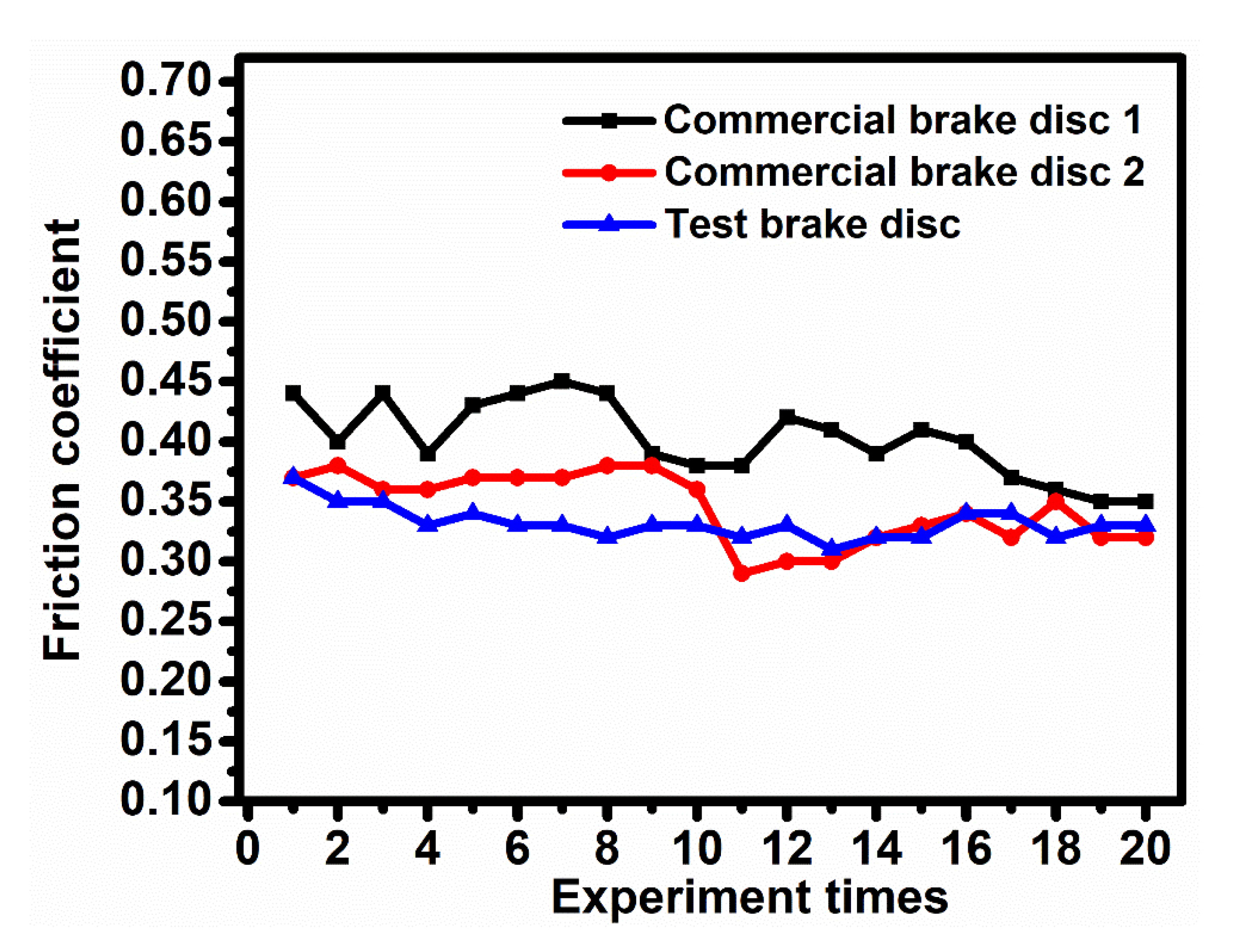
The produced test disc had a friction coefficient comparable to that of commercial disc 2 and lower than that of commercial disc 1. The test brake disc had a stable friction coefficient, with the friction coefficient dispersion decreasing to 3.90%, which was approximately 50% lower than those of the two commercial discs. The wear rate was intermediate between the two commercial discs;
(5)
The test brake disc’s production efficiency was 36% higher than that of commercial brake disc 1 manufactured using the TCVI process with gaseous propylene as the carbon source and, thus, provided a more cost-effective solution for C/C aircraft brake discs.

Author Contributions

Conceptualization, D.Z., H.C. (Hong Cui), J.L., P.G. and Q.G.; methodology, D.Z., H.C., J.L., P.G., H.C. (Hao Cheng), R.L., Q.L. and W.H.; software, D.Z., P.G. and H.C. (Hao Cheng); validation, D.Z., H.C. (Hong Cui) and P.G.; formal analysis, D.Z. and P.G.; investigation, D.Z., P.G., J.L., H.C. (Hao Cheng), R.L., Q.L. and W.H.; data curation, H.C. (Hong Cui); writing—original draft preparation, D.Z.; writing—review and editing, P.G.; project administration, H.C. (Hong Cui); funding acquisition, P.G. and Q.G. All authors have read and agreed to the published version of the manuscript.

Funding

This work was funded by the National Natural Science Foundation of China (51771140), Shaanxi Key Science and Technology Innovation Team (2017KCT-05), The Youth Innovation Team of Shaanxi Universities: Metal Corrosion Protection and Surface Engineering Technology, Shaanxi Provincial Key Research and Development Project (2019ZDLGY05-09, 2022GY-404), the Natural Science Foundation of Shandong Province (ZR2021ME041), the Local Serving Special Scientific Research Projects of Shaanxi Provincial Department of Education (19JC022), and the Project of Yulin Science and Technology Bureau (2019-121).

Institutional Review Board Statement

Not applicable.

Informed Consent Statement

Not applicable.

Data Availability Statement

Not applicable.

Conflicts of Interest

The authors declare no conflict of interest.

References

  1. Wu, S.; Yi, M.; Ge, Y.; Ran, L.; Peng, K. Effect of carbon fiber reinforcement on the tribological performance and behavior of aircraft carbon brake discs. Carbon 2017, 117, 279–292. [Google Scholar] [CrossRef]
  2. Hao, M.; Luo, R.; Hou, Z.; Yang, W.; Xiang, Q.; Yang, C. Effect of fiber-types on the braking performances of carbon/carbon composites. Wear 2014, 319, 145–149. [Google Scholar] [CrossRef]
  3. Yevtushenko, A.A.; Grzes, P.; Adamowicz, A. The temperature mode of the Carbon-Carbon Multi-Disc brake in the view of the interrelations of its operating characteristics. Materials 2020, 13, 1878. [Google Scholar] [CrossRef]
  4. Su, J.M.; Xiao, Z.C.; Liu, Y.Q.; Meng, F.C.; Peng, Z.G.; Gu, L.M.; Li, G.F.; Xing, R.P. Preparation and characterization of carbon/carbon aircraft brake materials with long service life and good frictional properties. New Carbon Mater. 2010, 25, 329–334. [Google Scholar] [CrossRef]
  5. Lyu, Y.; Olofsson, U. On black carbon emission from automotive disc brakes. J. Aerosol Sci. 2020, 148, 105610. [Google Scholar] [CrossRef]
  6. Sinnur, K.H.; Selvam, P.; Rao, J.G. Effect of type of carbon matrix on tribological properties of C/C aircraft brake discs. Defence Sci. J. 2019, 69, 585–590. [Google Scholar]
  7. Fan, S.-W.; Yang, C.; He, L.-Y.; Du, Y.; Krenkel, W.; Greil, P.; Travitzky, N. Progress of ceramic matrix composites brake materials for aircraft application. Rev. Adv. Mater. Sci. 2016, 44, 313–325. [Google Scholar]
  8. Zaghlou, M.M.Y.M. Mechanical properties of linear low-density polyethylene fire-retarded with melamine polyphosphate. J. Appl. Polym. Sci. 2018, 135, 46770. [Google Scholar] [CrossRef]
  9. Zaghloul, M.M.Y.; Steel, K.; Veidt, M.; Heitzmann, M.T. Wear behaviour of polymeric materials reinforced with man-made fibres: A comprehensive review about fibre volume fraction influence on wear performance. J. Reinf. Plast. Comp. 2021, 41, 215–241. [Google Scholar] [CrossRef]
  10. Ambrosio, E.P.; Pavese, M.; Biamino, S.; Epicoco, P.; Tulliani, J.M.; Fossati, P.; Marino, F.; Fino, P. Cost effective glassy carbon brake pad solution for automotive systems. Adv. Appl. Ceram. 2013, 111, 427–432. [Google Scholar] [CrossRef]
  11. Dietrich, S.; Gebert, J.M.; Stasiuk, G.; Wanner, A.; Weidenmann, K.A.; Deutschmann, O.; Tsukrov, I.; Piat, R. Microstructure characterization of CVI-densified carbon/carbon composites with various fiber distributions. Compos. Sci. Technol. 2012, 72, 1892–1900. [Google Scholar] [CrossRef]
  12. Zhao, J.-G.; Li, K.-Z.; Li, H.-J.; Wang, C. The influence of thermal gradient on pyrocarbon deposition in carbon/carbon composites during the CVI process. Carbon 2006, 44, 786–791. [Google Scholar] [CrossRef]
  13. Wu, S.; Liu, Y.; Ge, Y.; Ran, L.; Peng, K.; Yi, M. Structural transformation of carbon/carbon composites for aircraft brake pairs in the braking process. Tribol. Int. 2016, 102, 497–506. [Google Scholar] [CrossRef]
  14. Kumar, P.; Srivastava, V.K. Tribological behaviour of C/C–SiC composites-A review. J. Adv. Ceram. 2016, 5, 1–12. [Google Scholar] [CrossRef] [Green Version]
  15. Kim, H.-G.; Ji, W.; Kwon, H.J.; Yoon, S.; Kim, J.-I.; Bae, S.; Cho, N.C. Full-scale multi-physics numerical analysis of an isothermal chemical vapor infiltration process for manufacturing C/C composites. Carbon 2021, 172, 174–188. [Google Scholar] [CrossRef]
  16. Stadler, Z.; Krnel, K.; Kosmač, T. Friction and wear of sintered metallic brake linings on a C/C-SiC composite brake disc. Wear 2008, 265, 278–285. [Google Scholar] [CrossRef]
  17. Kepekci, H.; Kosa, E.; Ezgi, C.; Cihan, A. Three-dimensional CFD modeling of thermal behavior of a disc brake and pad for an automobile. Int. J. Low Carbon Technol. 2020, 15, 543–549. [Google Scholar] [CrossRef]
  18. Li, G.; Yan, Q.; Jianren, X.; Qi, G.; Yang, X. The Stability of the Coefficient of Friction and Wear Behavior of C/C–SiC. Tribol. Lett. 2015, 58, 13. [Google Scholar] [CrossRef]
  19. Aijun, L.; Hejun, L.; Kezhi, L.; Zhengbing, G. Applications of neural networks and genetic algorithms to CVI processes in carbon/carbon composites. Acta Mater. 2004, 52, 299–305. [Google Scholar] [CrossRef]
  20. Kuo, H.H.; Chern Lin, J.H.; Ju, C.P. Tribological behavior of fast-carbonized PAN/phenolic-based carbon/carbon composite and method for improving same. Wear 2005, 258, 1555–1561. [Google Scholar] [CrossRef]
  21. Li, G.; Yan, Q. Comparison of friction and wear behavior between C/C, C/C-SiC and metallic composite materials. Tribol. Lett. 2015, 60, 15. [Google Scholar] [CrossRef]
  22. Zhang, L.; She, D.; Shi, L. Influence of graphitization degree of nuclear graphite on HTGR reactor physics calculation. Ann. Nuc. Energy. 2020, 143, 107458. [Google Scholar] [CrossRef]
  23. Fan, S.; Zhang, L.; Xu, Y.; Cheng, L.; Tian, G.; Ke, S.; Xu, F.; Liu, H. Microstructure and tribological properties of advanced carbon/silicon carbide aircraft brake materials. Comp. Sci. Technol. 2008, 68, 3002–3009. [Google Scholar] [CrossRef]
  24. Cai, R.; Zhang, J.; Nie, X.; Tjong, J.; Matthews, D.T.A. Wear mechanism evolution on brake discs for reduced wear and particulate emissions. Wear 2020, 452–453, 203–283. [Google Scholar] [CrossRef]
  25. Fan, S.; Zhang, L.; Cheng, L.; Tian, G.; Yang, S. Effect of braking pressure and braking speed on the tribological properties of C/SiC aircraft brake materials. Comp. Sci. Technol. 2010, 70, 959–965. [Google Scholar] [CrossRef]
  26. Faga, M.G.; Casamassa, E.; Iodice, V.; Sin, A.; Gautier, G. Morphological and structural features affecting the friction properties of carbon materials for brake pads. Tribol. Int. 2019, 140, 105889. [Google Scholar] [CrossRef]
  27. Zhou, X.; Zhu, D.; Xie, Q.; Luo, F.; Zhou, W. Friction and wear properties of C/C–SiC braking composites. Ceram. Inter. 2012, 38, 2467–2473. [Google Scholar] [CrossRef]
  28. Gadow, R.; Jiménez, M. Carbon fiber-reinforced carbon composites for aircraft brakes. AM. Ceram. Soc. Bull. 2019, 98, 28–34. [Google Scholar]
  29. Yevtushenko, A.; Kuciej, M.; Topczewska, K. Frictional heating during braking of the C/C composite disc. Materials 2020, 13, 2691. [Google Scholar] [CrossRef]
  30. Zaghloul, M.M.Y.; Zaghloul, M.Y.M.; Zaghloul, M.M.Y. Experimental and modeling analysis of mechanical-electrical behaviors of polypropylene composites filled with graphite and MWCNT fillers. Polym. Test. 2017, 63, 467–474. [Google Scholar] [CrossRef]
  31. Mahmoud Zaghloul, M.Y.; Yousry Zaghloul, M.M.; Yousry Zaghloul, M.M. Developments in polyester composite materials—An in-depth review on natural fibres and nano fillers. Compos. Struct. 2021, 278, 114698. [Google Scholar] [CrossRef]
  32. Sharma, S.; Patel, B.; Patel, R. Friction and wear characteristics of robust carbon-carbon composites developed solely from petroleum pitch without reimpregnation. Friction 2019, 8, 945–956. [Google Scholar] [CrossRef] [Green Version]
  33. Policandriotes, T.; Filip, P. Effects of selected nanoadditives on the friction and wear performance of carbon–carbon aircraft brake composites. Wear 2011, 271, 2280–2289. [Google Scholar] [CrossRef]
  34. Goo, B.C. Tribological properties of a C/C–SiC–Cu composite brake disc. J. Frict. Wear. 2017, 38, 455–461. [Google Scholar] [CrossRef]
  35. Zhang, C.; Zhang, L.; Zeng, Q.; Fan, S.; Cheng, L. Simulated three-dimensional transient temperature field during aircraft braking for C/SiC composite brake disc. Mater. Design. 2011, 32, 2590–2595. [Google Scholar] [CrossRef]
  36. Shi, Q.; Xiao, P. Effect of pyrolytic carbon content on microstructure and tribological properties of C/C–SiC brake composites fabricated by isothermal chemical vapor infiltration. Solid State Sci. 2012, 14, 26–34. [Google Scholar] [CrossRef]
  37. Byeong-Choon, G.; In-Sik, C. Microstructural analysis and wear performance of Carbon-Fiber-Reinforced SiC composite for brake pads. Materials 2017, 10, 701. [Google Scholar] [CrossRef]
  38. Pevec, M.; Oder, G.; Potrč, I.; Šraml, M. Elevated temperature low cycle fatigue of grey cast iron used for automotive brake discs. Eng. Fail. Anal. 2014, 42, 221–230. [Google Scholar] [CrossRef]
  39. Fan, S.; Sun, H.; Ma, X.; Deng, J.; Yang, C.; Cheng, L.; Zhang, L. Microstructure and properties of a new structure-function integrated C/C-SiC brake material. J. Alloy. Compd. 2018, 769, 239–249. [Google Scholar] [CrossRef]
  40. Mohanty, R.M. Climate based performance of Carbon-Carbon disc brake for high speed aircraft braking system. Defence. Sci. J. 2013, 63, 531–538. [Google Scholar] [CrossRef] [Green Version]
  41. Li, W.; Yang, X.; Wang, S.; Xiao, J.; Hou, Q. Comprehensive analysis on the performance and material of automobile brake discs. Metals 2020, 10, 377. [Google Scholar] [CrossRef] [Green Version]
  42. Li, Z.; Xiao, P.; Zhang, B.-g.; Li, Y.; Lu, Y.-h. Preparation and tribological properties of C/C–SiC brake composites modified by in situ grown carbon nanofibers. Ceram. Inter. 2015, 41, 11733–11740. [Google Scholar] [CrossRef]
  43. Zhang, B.; Xiao, P.; Li, Y.; Li, Z.; Zhou, W.; Luo, H.; Lu, Y. Microstructures and tribological properties of carbon/carbon-boron nitride composites fabricated by powdered additives and chemical vapor infiltration. Ceram. Inter. 2017, 43, 7607–7617. [Google Scholar] [CrossRef]
  44. Kwak, N.S.; Kim, J.Y.; Gao, J.C. Detection of small-flaw in carbon brake disc (C-C) using air-coupled ultrasonic C-scan technique. Int. J. Precis. Eng. Man. 2017, 18, 987–994. [Google Scholar] [CrossRef]
  45. Djafri, M.; Bouchetara, M.; Busch, C.; Khatir, S.; Khatir, T.; Weber, S.; Shbaita, K.; Abdel Wahab, M. Influence of thermal fatigue on the wear behavior of brake discs sliding against organic and semimetallic friction materials. Trib. T. 2018, 61, 861–868. [Google Scholar] [CrossRef]
Figure 1. The preparation processes of the test discs.
Coatings 12 00768 g001
Figure 2. Variations in the densities of the test brake disc and commercial brake disc 1 over time.
Coatings 12 00768 g002
Figure 3. Densification rates of the test brake disc and commercial brake disc 1 over time.
Coatings 12 00768 g003
Figure 4. Microstructures of the pyrolytic carbons through a polarized light microscope: (a) rough layer; (b) smooth layer; (c) isotropic layer.
Coatings 12 00768 g004
Figure 5. Pyrolytic C/C microstructures of the three different types of brake discs: (a) test brake disc; (b) commercial brake disc 1; (c) commercial brake disc 2.
Coatings 12 00768 g005
Figure 6. Fracture surfaces of the three brake discs: (a) bend fracture of the test brake disc; (b) shear fracture of the test brake disc; (c) compression fracture of the test brake disc; (d) bend fracture of commercial brake disc 1; (e) shear fracture of commercial brake disc 1; (f) compression fracture of commercial brake disc 1; (g) bend fracture of commercial brake disc 2; (h) shear fracture of commercial brake disc 2; (i) compression fracture of commercial brake disc 2.
Coatings 12 00768 g006
Figure 7. Worn surfaces of the three brake discs after wear test: (a) test brake disc; (b) commercial brake disc 1; (c) commercial brake disc 2.
Coatings 12 00768 g007
Figure 8. Typical braking curves of the three C/C brake discs in dynamic tests at the design landing energy: (a) test brake disc; (b) commercial brake disc 1; (c) commercial brake disc 2.
Coatings 12 00768 g008
Figure 9. Variations in the friction coefficients of the three C/C brake discs with the number of braking tests.
Coatings 12 00768 g009
Figure 10. Typical braking curves of the three types of C/C brake discs in dynamic tests at an overload landing energy: (a) test brake disc; (b) commercial brake disc 1; (c) commercial brake disc 2.
Coatings 12 00768 g010aCoatings 12 00768 g010b
Table 1. Ground dynamic simulation test parameters.
Test ConditionBrake Pressure (MPa)Braking Speed (km/h)Braking Energy (MJ)
Designed landing energy8.0–11.523928.22
Overload landing energy9.0–11.527537.8
Static torque test20.7--
Table 2. Properties of pyrolytic carbon with different structures.
Structured002 (nm)Density (g/cm3)Thermal Conductivity (W/m·K)Extinction Angle
RL0.34612.07–2.1296.14Ae ≥ 18
SL0.34761.95–2.0725.0812 ≤ Ae < 18
ISO---4 ≤ Ae < 12
DL0.3541.66–1.7525.08Ae < 4
Table 3. Physical, mechanical and thermal properties of the three different types of brake discs.
PropertiesTest Brake DiscCommercial Brake Disc 1 (Envelope)Commercial Brake Disc 2 (Envelope)
Density (g/cm3)1.781.76~1.821.71~1.82
Graphitization degree (%)2718~547~14
Compressive strength
(axial direction) (MPa)
258211.4~280125~154
Bending strength
(radial direction) (MPa)
83.370.5~14049.6~81.6
Shearing strength
(radial direction) (MPa)
64.347.1~76.435.7~36.4
Thermal conductivity in the axial direction (800 °C) (W/m·K)25.7525.78~43.1525.24
Table 4. Distributions of the friction coefficient measurements of the three C/C brake discs (based on data from the first 20 tests at the design landing energy).
ExperimentMinimum ValueMaximum ValueMean
Value
Data RangeNumber of
Experiments
Coefficient of Dispersion
Test brake disc0.310.370.330.32~0.33203.90%
Commercial brake disc 10.350.450.400.37~0.44207.70%
Commercial brake disc 20.290.380.340.30~0.38208.45%
Table 5. Friction coefficients of the three brake discs in the dynamic tests at an overload landing energy.
ExperimentNumber of ExperimentsMean Friction Coefficient
Test brake disc10.34
Commercial brake disc 150.32
Commercial brake disc 260.28
Table 6. Friction coefficients of the three brake discs in static torque tests.
ExperimentNumber of
Experiments
Friction
Coefficient
Mean Friction
Coefficient
Test brake disc10.370.37
Commercial brake disc 130.23, 0.24, 0.270.25
Commercial brake disc 230.18, 0.21, 0.270.22
Table 7. Wear rates of the three brake discs at the design landing energy.
ExperimentNumber of
Experiments
Linear Wear Amount (mm)Linear Wear Rate
(10−3mm/(Times · Friction Surface))
Test brake disc200.310.97
Commercial brake disc 11011.520.94
Commercial brake disc 2620.970.98
Publisher’s Note: MDPI stays neutral with regard to jurisdictional claims in published maps and institutional affiliations.

