1. Introduction:
Titanium alloys are widely used in the aerospace industry due to their high specific strength, superior corrosion resistance and excellent mechanical properties at elevated temperatures. Ti6Al4V alloy is extensively used to manufacture critical structural parts in the aviation sector, such as aircraft frame beam structures, compressor blades, turbine blades, undercarriages and so forth [
1]. In recent years, with the rapid development of high-speed transport equipment, the demand for structural components with a higher strength, a higher reliability and a longer service life has increasingly risen.
During the last decade, additive manufacturing (AM) technologies have received extensive interest among researchers since they have various advantages against traditional processing methods in consideration of energy consumption, material utilization and design flexibility [
2]. Hence, an increasing number of institutes and enterprises have established their own AM processing systems. However, there are still several issues that restrict the application of AM technologies into actual mass production, such as limited productivity, anisotropic performance, high porosity and poor plasticity.
For metal materials, there are four typical AM technologies: wire arc additive manufactured (WAAM), selective laser melting (SLM), electron beam melting (EBM) and direct energy deposition (DED). Each of them has several nomenclatures by different scholars but share an identical processing principle. It is well known that there are many large-scale titanium components in an aircraft structure. However, manufacturing large-scale titanium parts using traditional methods involves a high buy-to-fly ratio due to the costly price and poor machinability of titanium alloys. In the future, manufacturing large-scale titanium components using AM technologies is of great practical significance in terms of both ecological and economic purpose. Among the common AM technologies, direct energy deposition (DED) is the best candidate, which owns a moderate deposition efficiency and controllable processing accuracy. In the laser cladding process, it is well known that the width and height of a single-track increase with the increase of the applied laser power. Therefore, a higher laser power in the DED process will consequently lead to an enhanced processing efficiency, thus shortening the processing time.
Hitherto, there are limited open literatures in relation to fabricating titanium components using AM technologies with a laser power greater than 4 kw. Ren et al. successfully fabricated a Ti6Al4V part using direct energy deposition with a laser power of 7.6 kw. Afterwards, he conducted a series of investigations regarding fatigue crack growth (FCG) behavior [
3] and low cycle fatigue (LCF) performance [
4,
5]. Wang et al. [
6] fabricated a Ti-6.5Al-3.5Mo-1.5Zr part using laser additive manufacturing (LAM) with a laser power of 4–6 kw, and clarified the relationship between microstructural anisotropy and FCG behavior. Brandl fabricated a Ti6Al4V part using wire-feed direct energy deposition with a laser power of 3.5 kw, and systematically studied the microstructure feature [
7] and tensile behavior [
8] of as-fabricated alloy.
In summary, limited investigations have been carried out regarding the microstructure characterization and fatigue performance of Ti6Al4V as it is part fabricated by HP-DED. Therefore, a deep understanding for the HP-DED process is still needed in terms of microstructure evolution, defect characterization and service performance. In the process of HP-DED, the formation of a keyhole is inevitable due to a higher heat input and subsequent recoil pressure caused by metallic vapor, which is the same as laser welding. The unstable molten pool and keyhole will consequently lead to greater entrapments of gas bubbles and a higher porosity, and could thus deteriorate the fatigue performance.
Processing-induced porosity is the main issue that restricts the application of AM fabricated components [
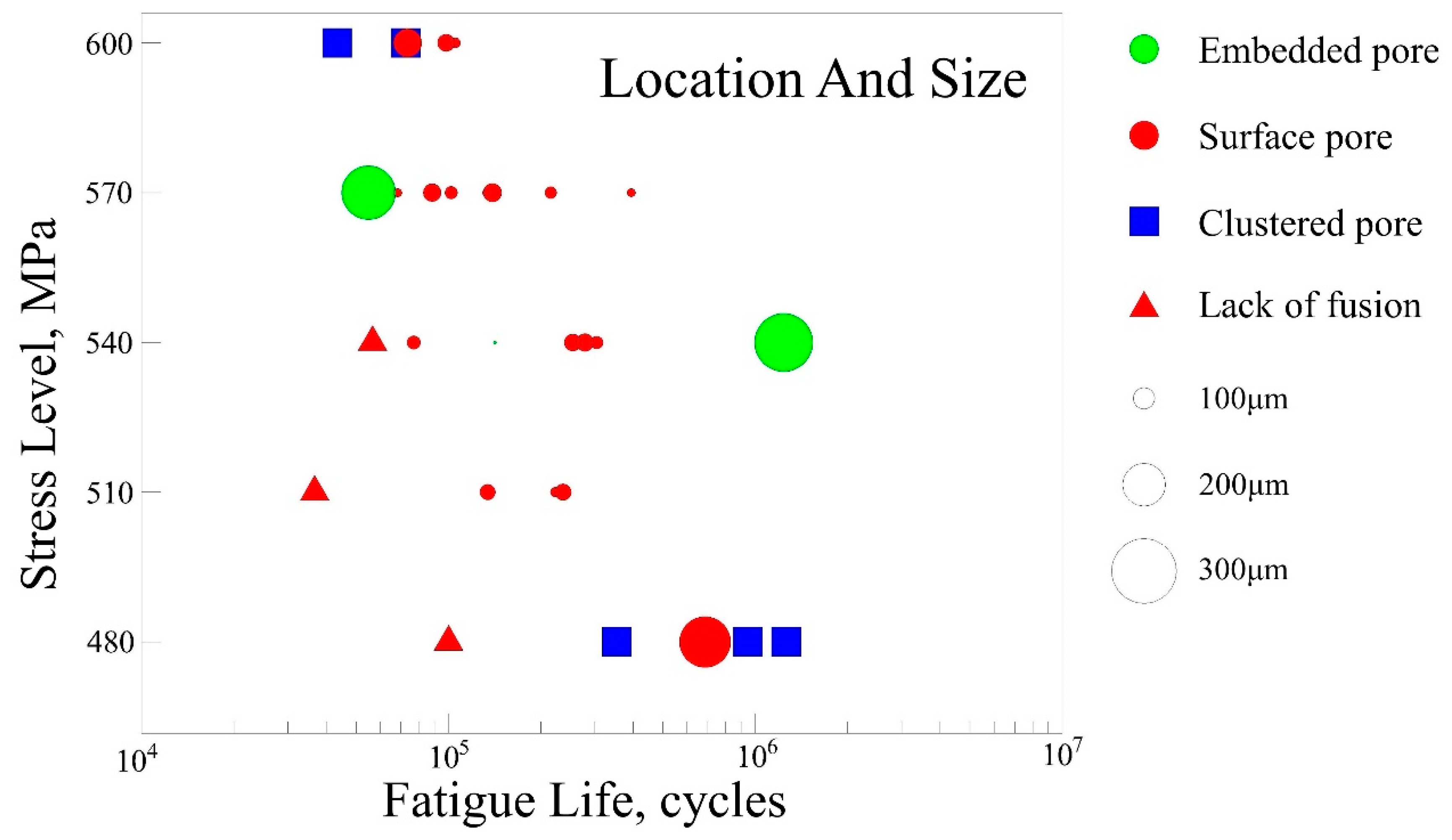
9]. There are three main porosity defects within AM fabricated parts.
A lack of fusion (LOF) occurs due to the insufficient laser energy input between layers, un-melted particles and pores with different shapes due to the entrapped gas bubbles during solidification [
10]. The effect of porosity on the fatigue life has been well established through statistical analysis methods in recent years [
11,
12,
13,
14,
15,
16,
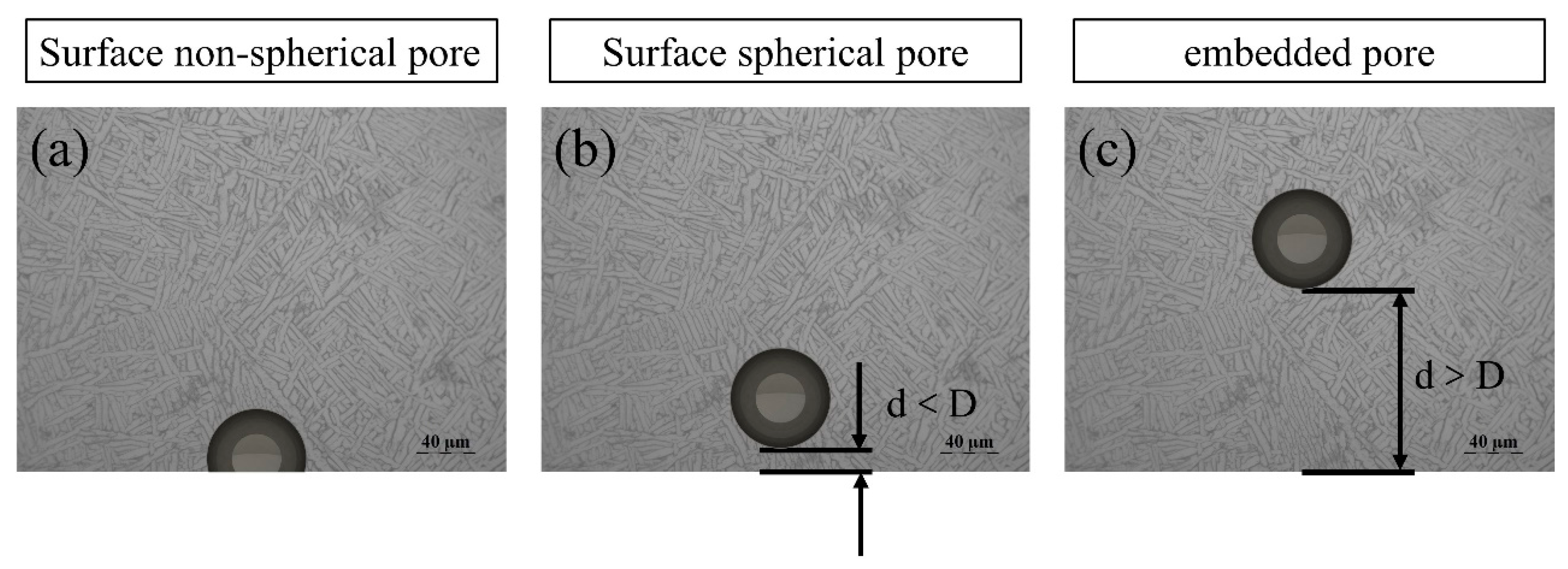
17], and a corresponding modified Kitagawa-Takahashi diagram has been proposed to predict the fatigue life. In addition, Romali Biswal studied the effect of the pore location on the fatigue performance of AM fabricated Ti6Al4V through finite element analysis [
18], and established the relationship between the stress concentration factor and pore shape. The result shows that the oblate spherical pore has the highest stress concentration factor. Moreover, machine learning is also a feasible approach for predicting the fatigue life of AM fabricated parts [
19,
20].
To the best knowledge of the authors, no investigation has been published to date in relation to the effect of processing-induced porosity on fatigue performance of Ti6Al4V parts fabricated by HP-DED. In the present work, the high cycle fatigue (HCF) performance of HP-DED fabricated Ti6Al4V parts was investigated. The influence of porosity on HCF performance is thoroughly discussed.
2. Experimental Material and Methods
2.1. Manufacturing Procedures
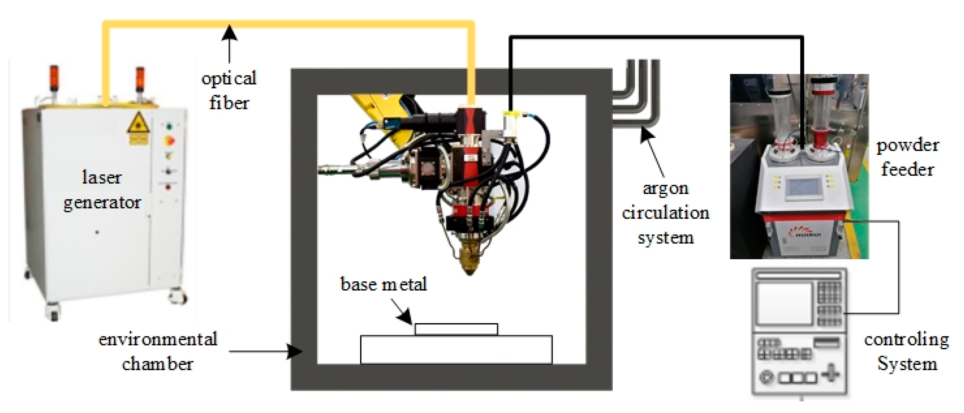
In an enclosed environmental chamber, an additive manufacturing (AM) system was established based on coaxially powder-blown direct energy deposition. Specifically, the AM system consisted of an argon atmosphere protecting chamber with a volume of approximately 20 cubic meters, a laser generator with a maximum output power of 6 kw, a three-axis CNC controlling mechanism, a powder feeder, an argon circulatory system, and an integrated controlling computer. The layout of the whole AM system is schematically shown in
Figure 1.
Ti6Al4V wrought plate and Ti6Al4V commercial powder (provided by Xi’an Bright Laser Technologies Co., Ltd., Xi’an, China) were used as a base metal and a feedstock material, respectively. Chemical composition of the powder is characterized by a high-frequency combustion infrared absorption method (C element), inert gas melting thermal conductivity method (O, N, H elements) and an inductively coupled plasma optical emission spectrometer method (other elements), which is listed in
Table 1. Prior to the high-power direct energy deposition (HP-DED) process, the circulatory system was activated to pump argon gas into the chamber until the content of oxygen is below 30 ppm. The inner pressure of the chamber was kept slightly higher than the ambient pressure during the manufacturing process. The optimum processing parameters have been determined through previous single-track experiments, which are listed in
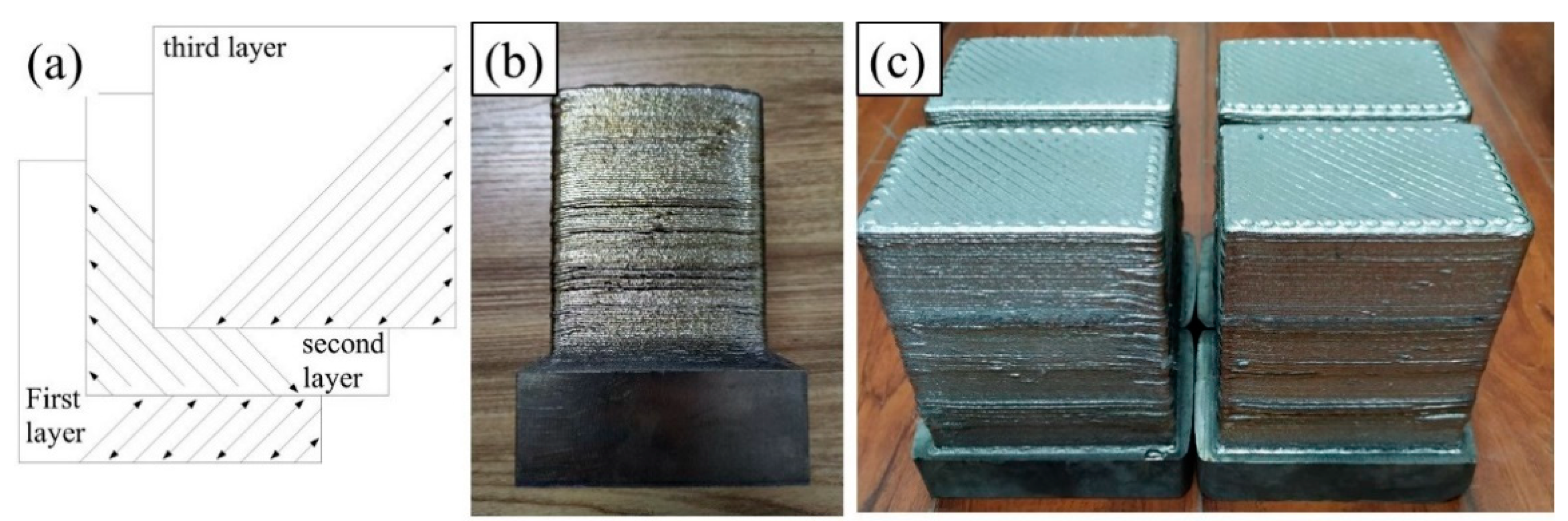
Table 2. In addition, the scanning direction was kept at 90 degrees between the two successive layers for diminishing the residual stress and deformation, which is shown in
Figure 2a.
In order to study the effect of processing-induced porosity on fatigue performance, two batches of powder materials were prepared and one of them was deliberately contaminated. The powder was contaminated by being placed in the ambient environment for several hours without protection. Afterwards, two Ti6Al4V bulks were deposited using original powder and contaminated powder, respectively. For simplicity, the fabricated parts with the contaminated powder and the original powder were denoted as bulk1 and bulk2 in the remaining parts, respectively. The macroscopic morphology of the two bulks in their as-deposited state are shown in
Figure 2b,c.
2.2. Microstructure Characterization, Tensile Testing and Fatigue Testing
The fabricated bulks were taken from the chamber after the HP-DED process was finished. Subsequently, the as-deposited bulks were separated from the base metal, and the additional material on the rough surface was removed by milling. The middle section in the height of the fabricated parts was chosen as the representative zone for subsequent characterization.
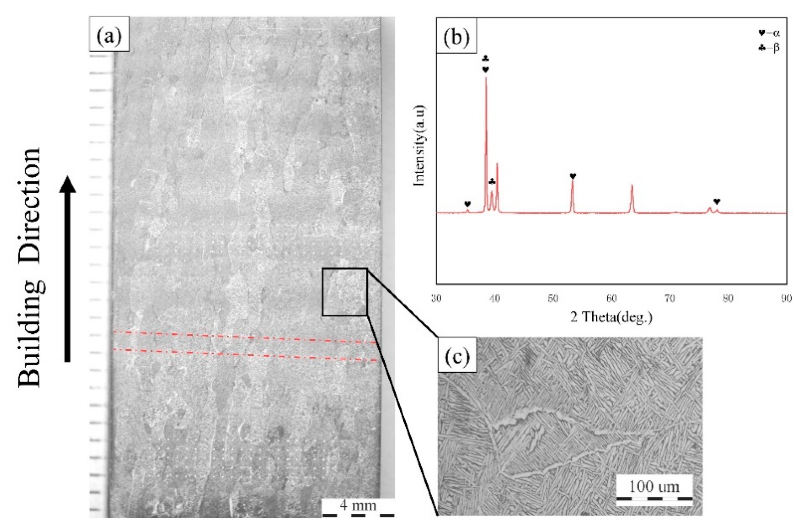
Specimens used for metallography characterization, tensile testing and high cycle fatigue (HCF) testing were cut by electric discharging machining. Then, the specimen for microstructure observation was prepared according to standard metallographic procedures, including mounting with resin and polishing with silica suspension. Subsequently, the scratches in the specimen were removed with a MIR-EPLAB-01 electrolytic polishing instrument, and then a solution of 5 mL HF, 12 mL HN3O, and 83 mL H2O was used to etch the specimen. The macroscopic morphology and microstructure were observed using a stereo microscope and an optical microscope (ZEISS Observer.A1m, Gottingen, Germany), respectively.
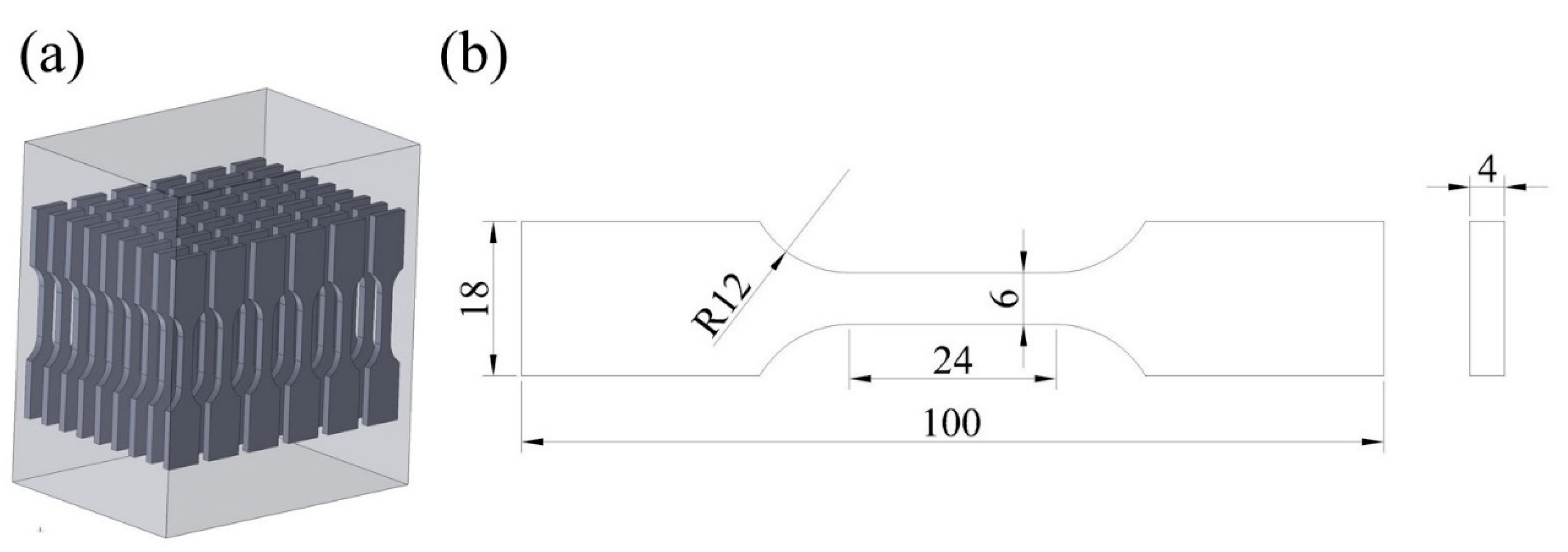
Axial tensile testing was conducted using an electronic universal tester (MTS-CMT5105, MTS, Eden Prairie, MN, USA) at room temperature. During the testing, an extensometer was fixed on the specimen to obtain a more accurate value of deformation. The ultimate tensile strength (UTS), yield strength (YS) and elongation (EI) were calculated by the average value of three specimens. The specimens for HCF testing were cut out along the deposition direction (i.e., height direction), with the sampling configuration and the dimension of the specimen as shown in
Figure 3.
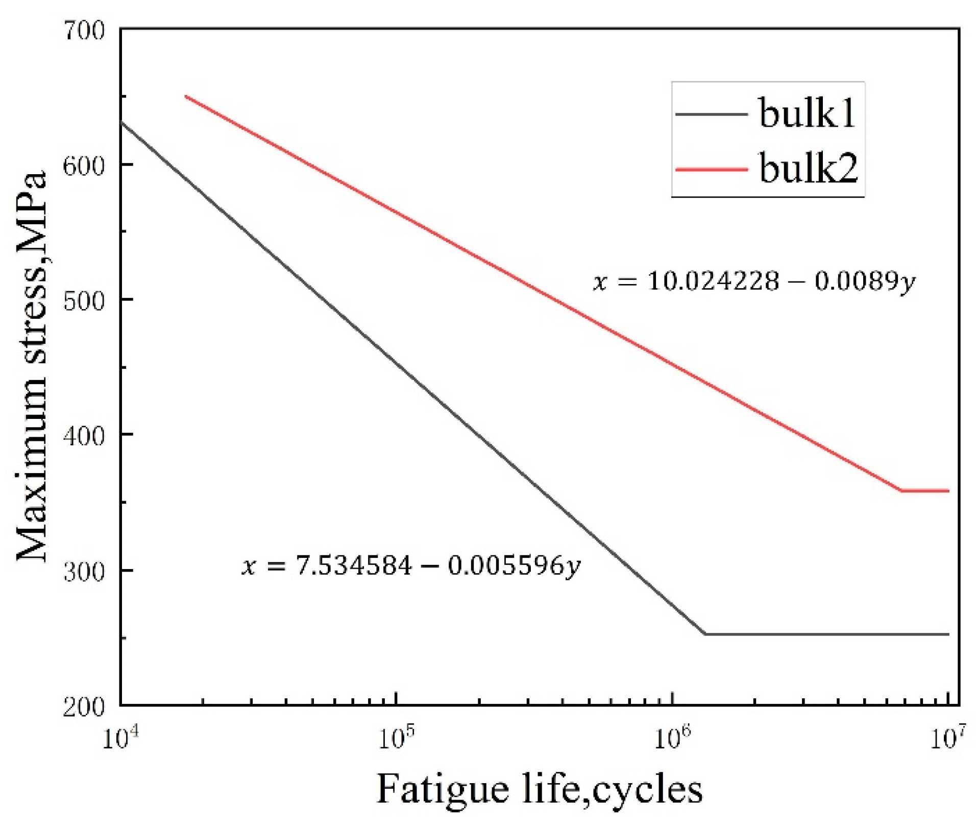
Load-controlled axial fatigue tests were conducted using a QBG-100 fatigue tester in air and ambient temperature, with a stress ratio of 0.1 and a frequency range from 80 to 90 Hz. The testing frequency was controlled by the fatigue tester automatically, which is related to the intrinsic property of the material. Referring to ISO 12107-2003, a staircase method and a group method were employed to obtain the fatigue limit and the S-N curve of the HP-DED fabricated Ti6Al4V part, respectively. The mean value and the standard deviation of the fatigue strength were calculated using the following equations.
where
is the minimum stress level in the fracture case,
is the stress spacing10 MPa for bulk1 and 20 MPa for bulk2, and
are the parameters relating to the testing results. The high cycle fatigue (HCF) testing was interrupted above 10
7 cycles if the specimen did not fail and if the unbroken specimen was denoted as a “run-out”.
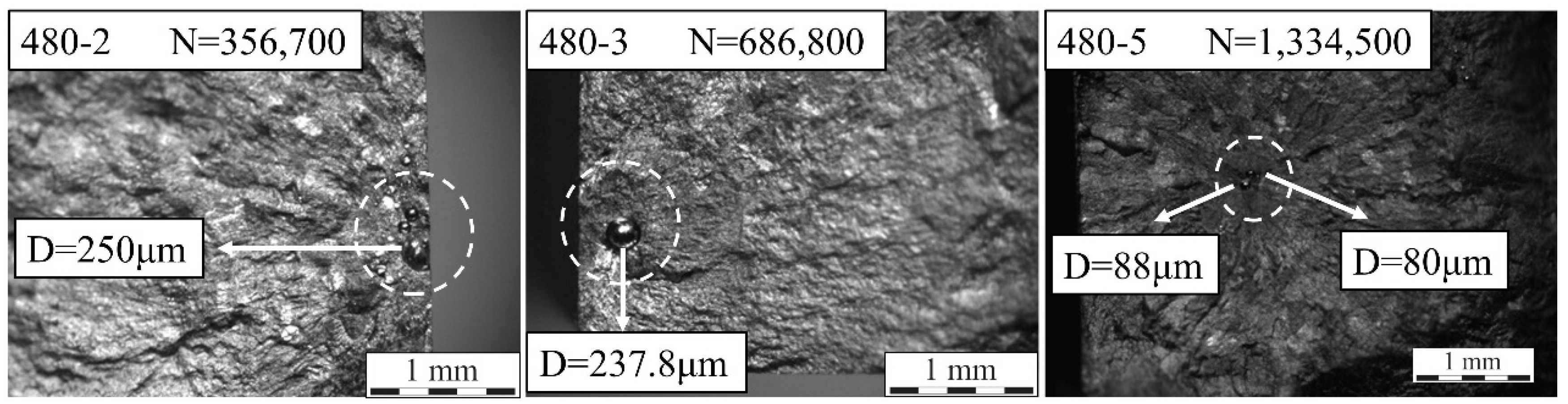
For the group method, the selected stress level for bulk1 is in a range from 300 MPa to 540 MPa, with a spacing of 30 MPa. Two specimens were tested in each stress step in consideration of the limited bulk material. The selected stress level for bulk2 is in a range from 480 MPa to 600 MPa, with a spacing of 30 MPa, and the sample size of each stress step is 6–7. Finally, the S-N curve of the two bulks were depicted according to the results of the group method. The fracture surface of the failed specimens was cut by electric discharging machining (EDM) and was cleaned in anhydrous alcohol ultrasonically. Subsequently, a stereo microscope and a scanning electron microscope (ZEISS Gemini 300, Oberkochen, Germany) were used to observe the fracture morphology. The equivalent diameter of the defect and the distance from the free surface were measured under scanning electron microscope (SEM) for subsequent analysis.


 ,
, 


