
Microstructure and Tribological Properties of Lubricating-Reinforcing Laser Cladding Composite Coating with the Ti2SC-Ti2Ni Mosaic Structure Phase

Abstract
:1. Introduction
2. Materials and Methods
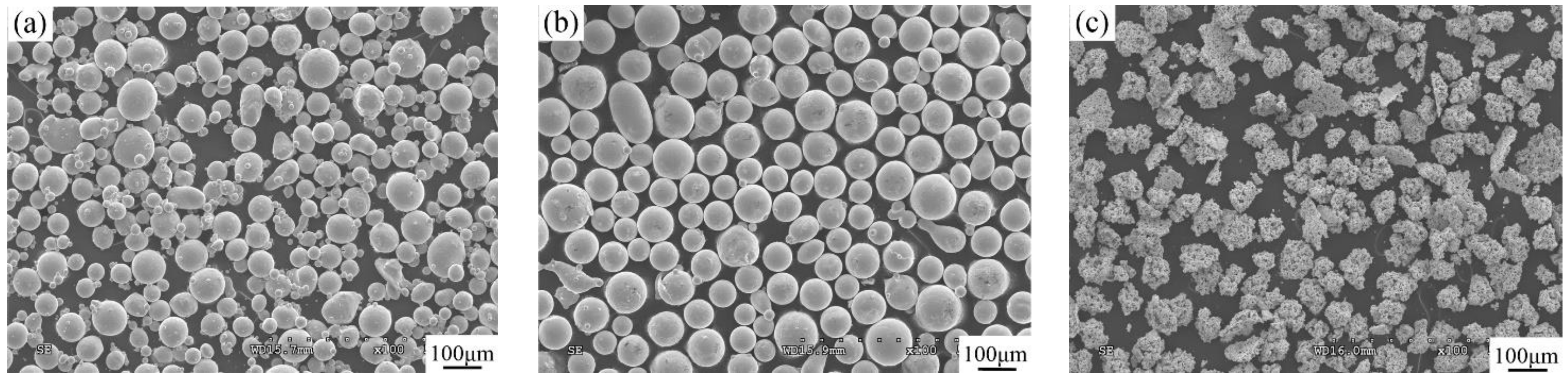
2.1. Materials
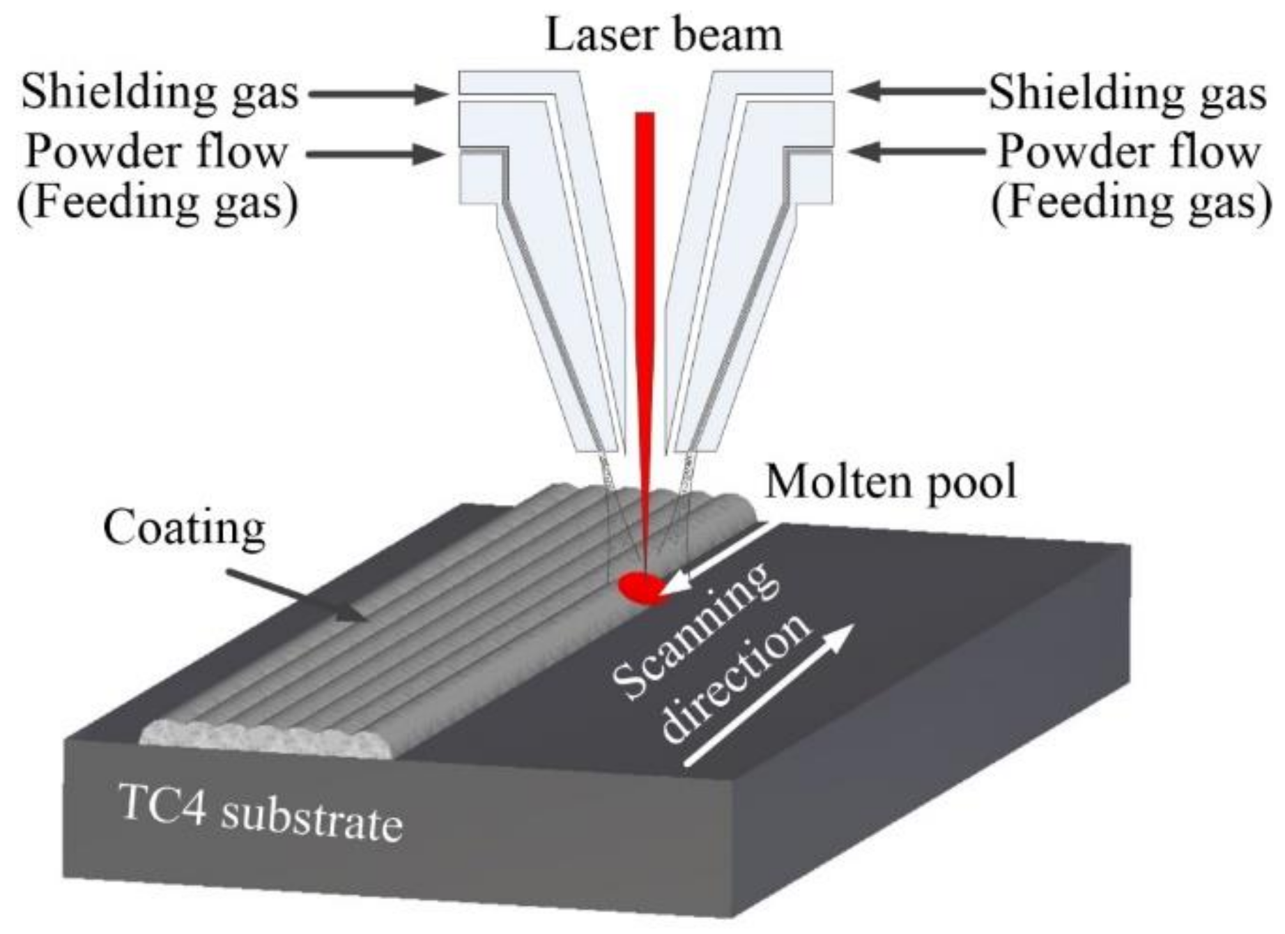
2.2. Preparation and Laser Cladding Process
2.3. Microstructure Characterization and Property Tests
3. Results and Discussion
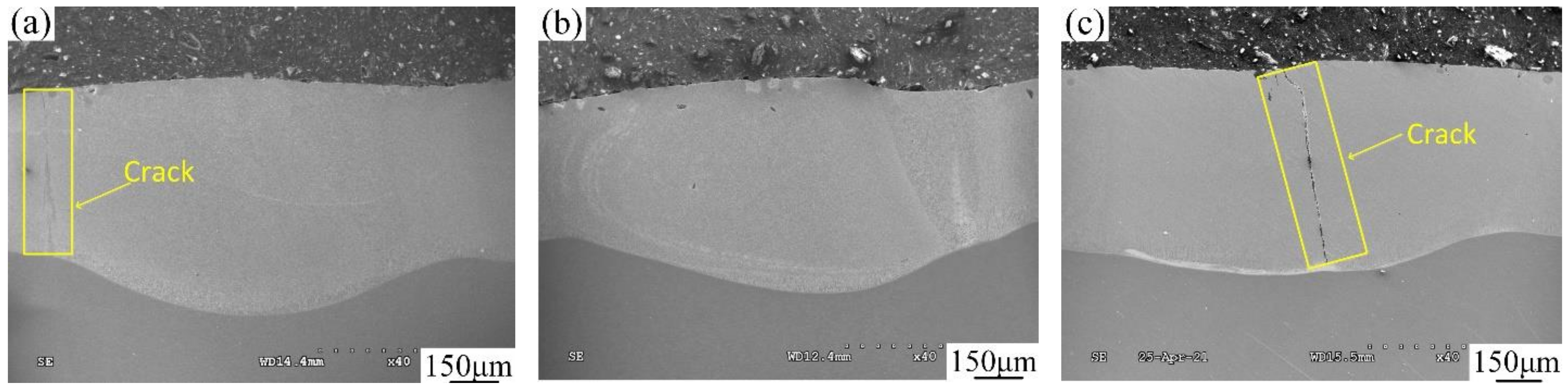
3.1. Cross-Sectional Morphology
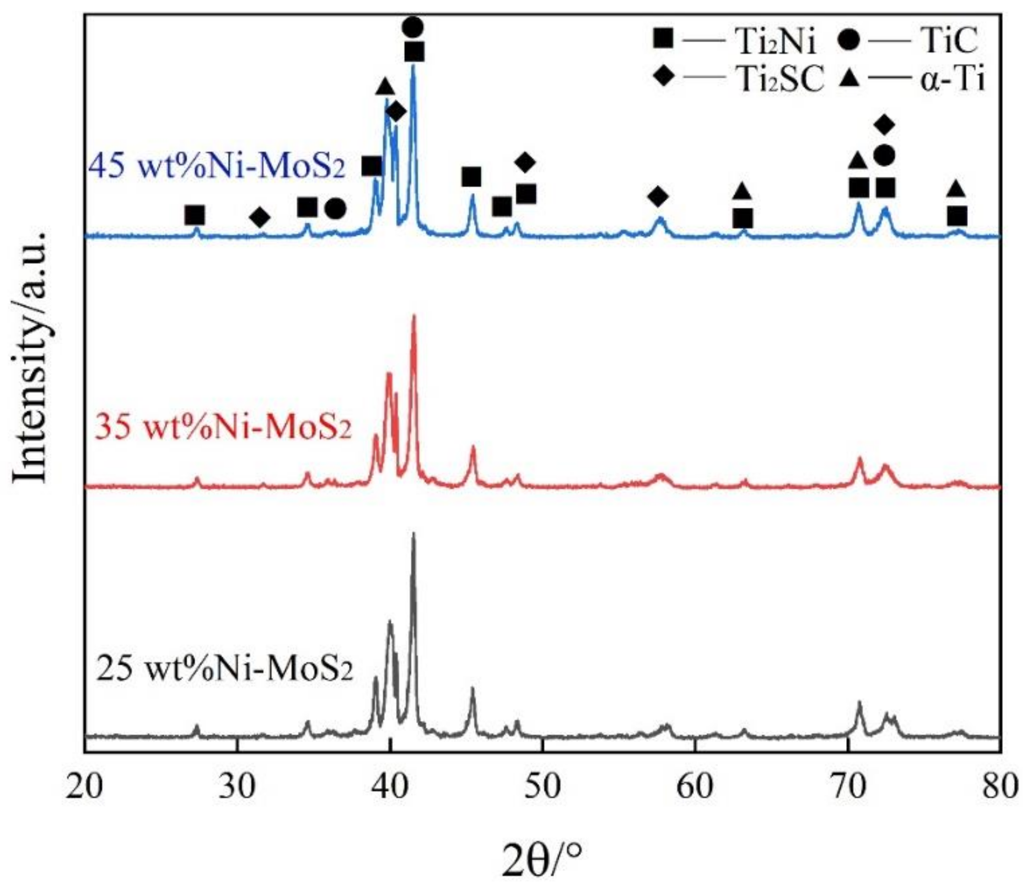
3.2. Phase Composition
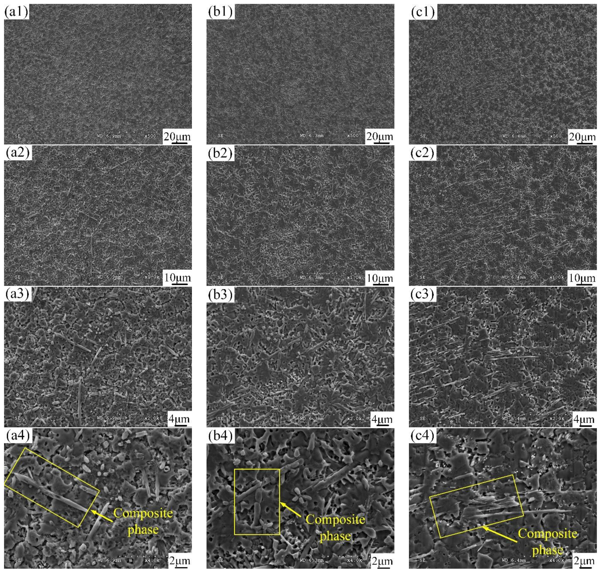
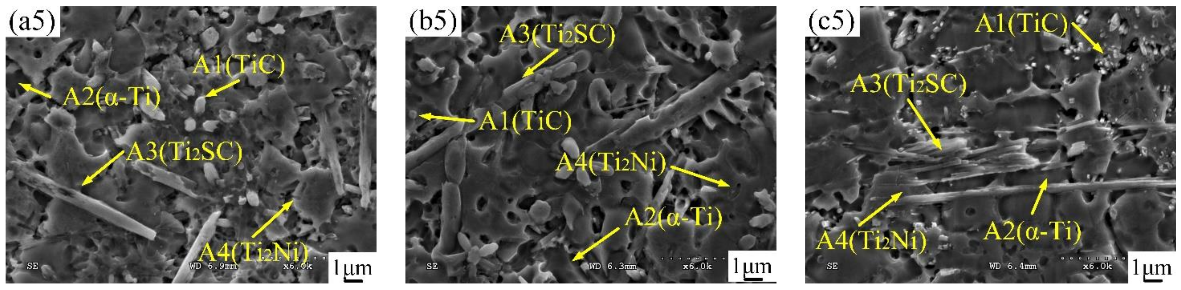
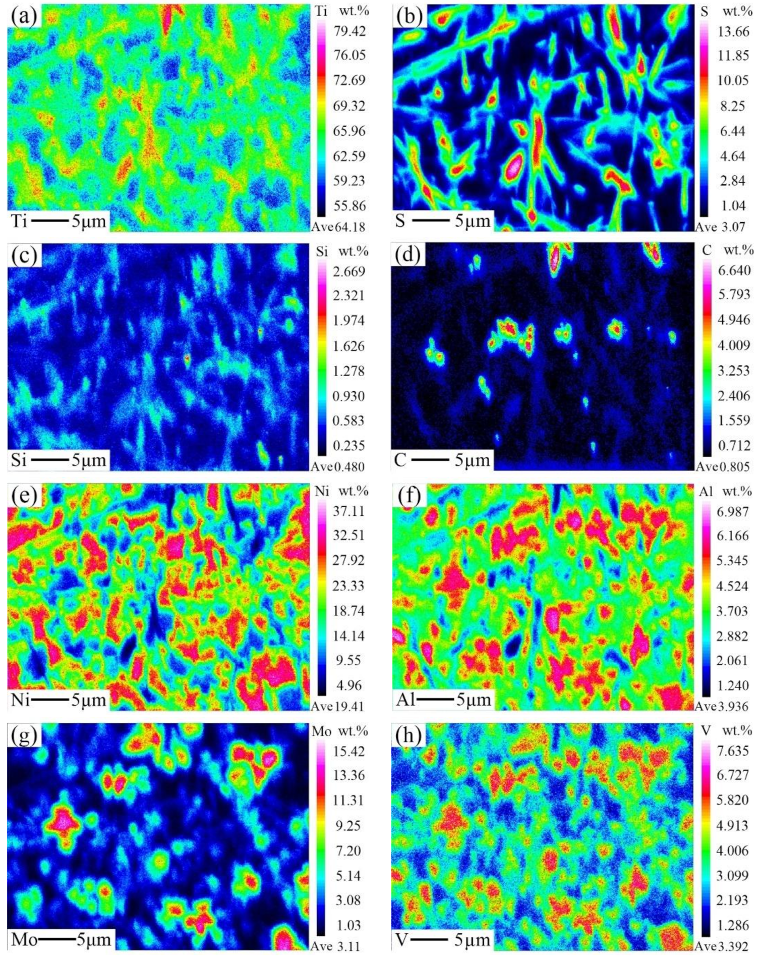
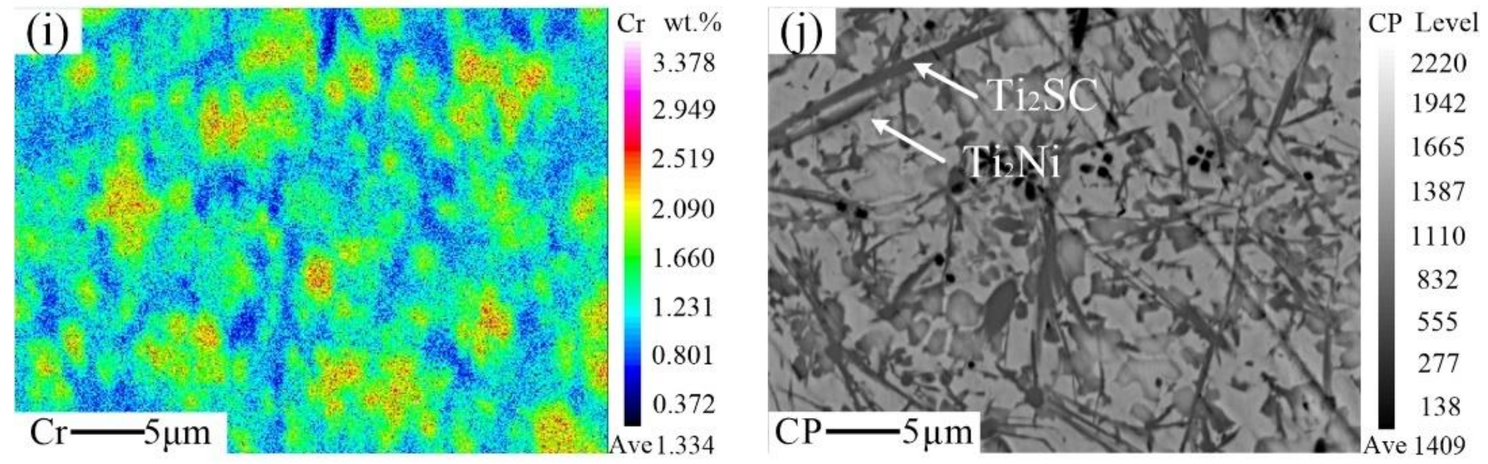
3.3. Microstructural Characterization
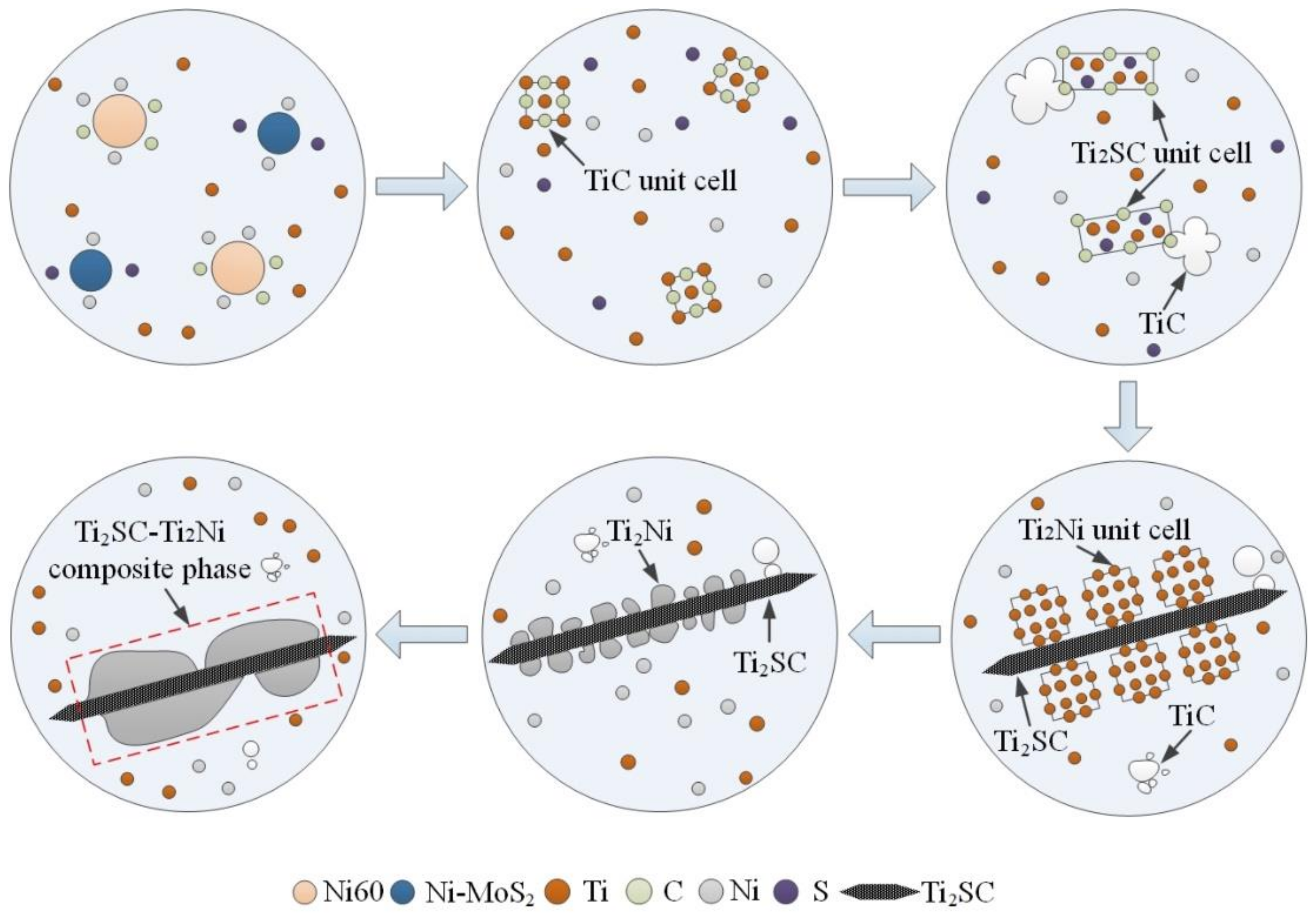
3.4. Formation Mechanism of the Ti2SC–Ti2Ni Mosaic Structure Phase
3.5. Microhardness
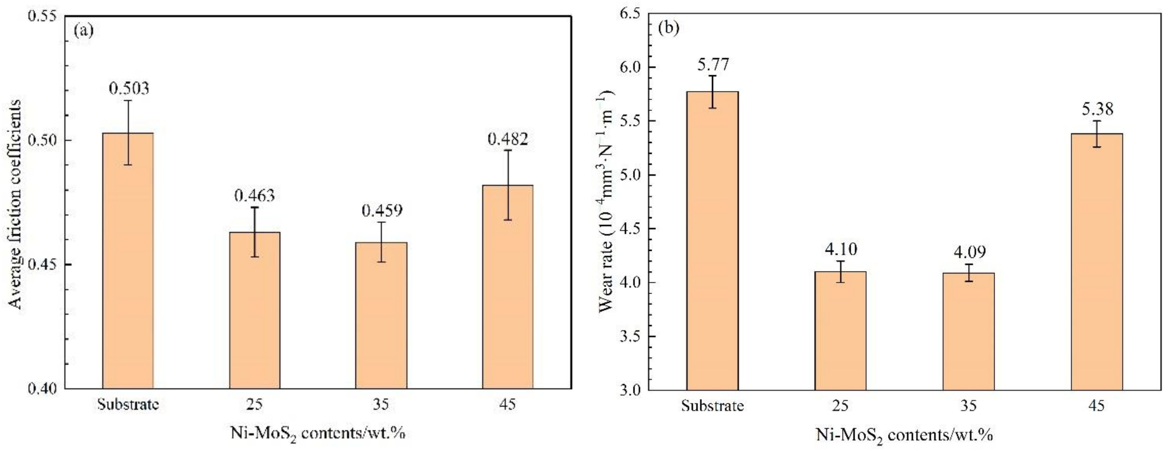
3.6. Tribological Properties
4. Conclusions
Author Contributions
Funding
Institutional Review Board Statement
Informed Consent Statement
Data Availability Statement
Conflicts of Interest
References
- Weng, F.; Yu, H.J.; Chen, C.Z.; Liu, J.L.; Zhao, L.J.; Dai, J.J.; Zhao, Z.H. Effect of process parameters on the microstructure evolution and wear property of the laser cladding coatings on Ti-6Al-4V alloy. J. Alloys Compd. 2017, 692, 989–996. [Google Scholar] [CrossRef]
- Zhao, Z.; Chen, J.; Guo, S.; Tan, H.; Lin, X.; Huang, W.D. Influence of α/β interface phase on the tensile properties of laser cladding deposited Ti-6Al-4V titanium alloy. J. Mater. Sci. Technol. 2017, 33, 675–681. [Google Scholar] [CrossRef]
- Nabhani, M.; Razavi, R.S.; Barekat, M. Corrosion study of laser cladded Ti-6Al-4V alloy in different corrosive environments. Eng. Fail. Anal. 2019, 97, 234–241. [Google Scholar] [CrossRef]
- Zhang, T.G.; Zhuang, H.F.; Zhang, Q.; Yao, B.; Yang, F. Influence of Y2O3 on the microstructure and tribological properties of Ti-based wear-resistant laser-clad layers on Ti6Al4V alloy. Ceram. Int. 2020, 46, 13711–13723. [Google Scholar] [CrossRef]
- Deng, C.; Wang, C.; Chai, L.J.; Wang, T.; Luo, J. Mechanical and chemical properties of CoCoFoNoMo0.2 high entropy alloy coating fabricated on Ti6Al4V by laser cladding. Intermetallics 2022, 144, 107504. [Google Scholar] [CrossRef]
- Zhu, L.D.; Xue, P.S.; Lan, Q.; Meng, G.R.; Ren, Y.; Yang, Z.C.; Xu, P.H.; Liu, Z. Recent research and development status of Laser Cladding: A Review. Opt. Laser Technol. 2021, 138, 106915. [Google Scholar] [CrossRef]
- Liu, Y.N.; Ding, Y.; Yang, L.J.; Sun, R.L.; Zhang, T.G.; Yang, X.J. Research and progress of laser cladding on engineering alloys: A review. J. Manuf. Process. 2021, 66, 341–363. [Google Scholar] [CrossRef]
- Berger, L.M.; Sempf, K.; Sohn, Y.J.; Vaßen, R. Influence of feedstock powder modification by heat treatments on the properties of APS-Sprayed Al2O3-40% TiO2 coatings. J. Therm. Spray Technol. 2018, 27, 654–666. [Google Scholar] [CrossRef]
- Basha, M.T.; Srikanth, A.; Venkateshwarlu, B. A critical review on nano structured coatings for Alumina-Titania (Al2O3-TiO2) deposited by Air Plasma Spraying Process (APS). Mater. Today 2020, 22, 1554–1562. [Google Scholar] [CrossRef]
- Paleu, C.C.; Munteanu, C.; Istrate, B.; Bhaumik, S.; Vizureanu, P.; Bălţatu, M.S.; Paleu, V. Microstructural analysis and tribological behavior of AMDRY 1371 (Mo–NiCrFeBSiC) atmospheric plasma spray deposited thin coatings. Coatings 2020, 10, 1186. [Google Scholar] [CrossRef]
- Yao, H.; Zhou, Z.; Xue, Y.; Zhou, Z.; Tan, Z.; He, D.; Wang, L. Microstructure and thermal conductivity of wire-arc sprayed FeCrNbBSiC amorphous coating. J. Alloys Compd. 2019, 788, 514–521. [Google Scholar] [CrossRef]
- Boulos, M.I. RF induction plasma spraying: State-of-the-art review. J. Therm. Spray Technol. 1992, 1, 33–40. [Google Scholar] [CrossRef]
- Junior, P.R.C.A.; Pukasiewicz, A.G.M. Evaluation of microstructure, mechanical and tribological properties of a Babbitt alloy deposited by arc and flame spray processes. Tribol. Int. 2019, 131, 148–157. [Google Scholar] [CrossRef]
- Kuroda, S.; Kawakita, J.; Watanabe, M.; Katanoda, H. Warm spraying—A novel coating process based on high-velocity impact of solid particles. Sci. Technol. Adv. Mater. 2008, 9, 033002. [Google Scholar] [CrossRef]
- Srinivasa, R.D.; Sivakumar, G.; Sen, D.; Joshi, S.V. Detonation sprayed coatings and their tribological performances. In Thermal Sprayed Coatings and their Tribological Performances; IGI Global: Hershey, PA, USA, 2015; pp. 294–327. [Google Scholar] [CrossRef] [Green Version]
- Zhou, Z.Y.; Liu, X.B.; Zhuang, S.G.; Yang, X.H.; Wang, M.; Sun, C.F. Preparation and high temperature tribological properties of laser in-situ synthesized self-lubricating composite coatings containing metal sulfides on Ti6Al4V alloy. Appl. Surf. Sci. 2019, 481, 209–218. [Google Scholar] [CrossRef]
- Ke, J.; Liu, X.B.; Liang, J.; Liang, L.; Luo, Y.S. Microstructure and fretting wear of laser cladding self-lubricating anti-wear composite coatings on TA2 alloy after aging treatment. Opt. Laser Technol. 2019, 119, 105599. [Google Scholar] [CrossRef]
- Liu, X.B.; Liu, H.Q.; Meng, X.J.; Sun, C.F.; Wang, M.D.; Qi, L.H.; Shi, G.L.; Wu, S.H. Effects of aging treatment on microstructure and tribological properties of nickel-based high-temperature self-lubrication wear resistant composite coatings by laser cladding. Mater. Chem. Phys. 2014, 143, 616–621. [Google Scholar] [CrossRef]
- Lan, X.D.; Wu, H.; Liu, Y.; Zhang, W.D.; Li, R.D.; Chen, S.Q.; Zai, X.F.; Hu, T. Microstructures and tribological properties of laser cladded Ti-based metallic glass composite coatings. Mater. Char. 2016, 120, 82–89. [Google Scholar] [CrossRef]
- Torres, H.; Vuchkov, T.; Ripoll, M.R.; Prakash, B. Tribological behavior of MoS2-based self-lubricating laser cladding for use in high temperature applications. Tribol. Int. 2018, 126, 153–165. [Google Scholar] [CrossRef]
- Shen, C.; Li, C.G.; Guo, Y.J.; Liu, C.M.; Zhang, X.J.; Feng, X.S. Modeling of temperature distribution and clad geometry of the molten pool during laser cladding of TiAlSi Alloys. Opt. Laser Technol. 2021, 142, 107277. [Google Scholar] [CrossRef]
- Feng, Z.C.; Liu, Y.F.; Li, Y.; Sun, G.B.; Zhang, Z.; Shi, C.X. Microstructure and high temperature reciprocating sliding wear properties of MoSi2/TiC/γ-Ni composite coating in-situ synthesized by co-axial powder feeding plasma transferred arc cladding. Tribol. Int. 2019, 129, 82–91. [Google Scholar] [CrossRef]
- Zhao, X.Y.; Ma, L.Q.; Ding, Y.; Shen, X.D. Structural evolution and electrochemical hydrogenation behavior of Ti2Ni alloy. Intermetallics 2010, 18, 1086–1090. [Google Scholar] [CrossRef]
- Hoseini, S.M.; Heidarpour, A.; Ghasemi, S. On the mechanism of mechanochemical synthesis of Ti2SC from Ti/FeS2/C mixture. Adv. Powder Technol. 2019, 30, 1672–1677. [Google Scholar] [CrossRef]
- Zhai, Y.J.; Liu, X.B.; Qiao, S.J.; Wang, M.D.; Lu, X.L.; Wang, Y.G.; Chen, Y.; Ying, L.X. Characteristics of laser clad α-Ti/TiC+(Ti,W)C1−x/Ti2SC+TiS composite coatings on TA2 titanium alloy. Opt. Laser Technol. 2017, 89, 97–107. [Google Scholar] [CrossRef]
- Zhu, W.B.; Song, J.H.; Mei, B.C. Kinetics and microstructure evolution of Ti2SC during in situ synthesis process. J. Alloys Compd. 2013, 566, 191–195. [Google Scholar] [CrossRef]
- Tao, Y.F.; Li, J.; Lü, Y.H.; Hu, L.F. Residual stress distribution in different depths of TiNi/Ti2Ni-based laser clad coating prepared at different environmental temperatures. Trans. Nonferrous Met. Soc. China 2017, 27, 2043–2054. [Google Scholar] [CrossRef]
- Zhou, W.B.; Liu, L.; Zhu, J.Q.; Tian, S.Q. Facile Synthesis of High-Purity Ti2SC Powders by Spark Plasma Sintering Technique. Ceram. Int. 2017, 43, 9363–9368. [Google Scholar] [CrossRef]
- Ivanovic, N.; Rodic, D.; Koteski, V.; Radisavljevic, I.; Novakovic, N.; Marjanovic, D.; Manasijevic, M.; Koicki, S. Cluster approach to the Ti2Ni structure type. Acta Cryst. 2006, B62, 1–8. [Google Scholar] [CrossRef]
- Qu, C.C.; Li, J.; Bai, L.L.; Shao, J.Z.; Song, R.; Chen, J.L. Effects of the thickness of the pre-placed layer on microstructural evolution and mechanical properties of the laser-clad coatings. J. Alloys Compd. 2015, 644, 450–463. [Google Scholar] [CrossRef]
- Bramfitt, B.L. The Effect of Carbide and Nitride Additions on the Heterogeneous Nucleation Behavior of Liquid Iron. Metall. Trans. 1970, 7, 1987–1995. [Google Scholar] [CrossRef]
- Du, Y.L.; Sun, Z.M.; Hashimoto, H.; Tian, W.B. First-Principles Study on Electronic Structure and Elastic Properties of Ti2SC. Phys. Lett. A 2008, 372, 5220–5223. [Google Scholar] [CrossRef]
- Gao, Z.T.; Ren, H.B.; Yuan, Y.; Gao, Z.M.; Liu, E.Y.; Zhang, C.W. Effect of CeO2 on the Microstructure and Microhardness of Laser-Cladded Ni60 on 35CrMoV Alloys. Micron 2021, 150, 103146. [Google Scholar] [CrossRef] [PubMed]
- Ertugrul, O.; Enrici, T.M.; Paydas, H.; Saggionetto, E.; Boschini, F.; Mertens, A. Laser Cladding of TiC Reinforced 316L Stainless Steel Composites: Feedstock Powder Preparation and Microstructural Evaluation. Powder Technol. 2020, 375, 384–396. [Google Scholar] [CrossRef]
- Zhao, T.; Zhang, S.; Zhou, F.Q.; Zhang, H.F.; Zhang, C.H.; Chen, J. Microstructure Evolution and Properties of in-situ TiC Reinforced Titanium Matrix Composites Coating by Plasma Transferred Arc Welding (PTAW). Surf. Coat. Technol. 2021, 424, 127637. [Google Scholar] [CrossRef]
- Das, A.K.; Shariff, S.M.; Choudhury, A.R. Effect of rare earth oxide (Y2O3) addition on alloyed layer synthesized on Ti-6Al-4V with Ti + SiC + h-BN mixed precursor by laser surface engineering. Tribol. Int. 2016, 95, 35–43. [Google Scholar] [CrossRef]


| No. | Coating | Composition of the Cladding Materials/wt.% | ||
|---|---|---|---|---|
| Ti6Al4V | Ni60 | Ni-MoS2 | ||
| 1 | 25 wt.% Ni-MoS2 coating | 35 | 40 | 25 |
| 2 | 35 wt.% Ni-MoS2 coating | 35 | 30 | 35 |
| 3 | 45 wt.% Ni-MoS2 coating | 35 | 20 | 45 |
| Materials | Elements (wt.%) | |||||||||||
|---|---|---|---|---|---|---|---|---|---|---|---|---|
| Ti | Al | V | Fe | C | N | O | H | Ni | Cr | B | Si | |
| Ti6Al4V | Bal. | 5.5–6.75 | 3.5–4.5 | ≤0.3 | ≤0.08 | ≤0.05 | ≤0.02 | ≤0.015 | - | - | - | - |
| Ni60 | - | - | - | ≤17.0 | 1.0–2.0 | - | - | - | Bal. | 14–18 | 2.5–4.5 | 3.5–4.5 |
| Process Parameter | Value | Process Parameter | Value |
|---|---|---|---|
| Power | 1100 W | Feeding gas flow rate | 7.0 L/min |
| Scanning speed | 400 mm/min | Shielding gas flow rate | 11.0 L/min |
| Spot diameter | 3.0 mm | Laser focus | 16.0 mm |
| Powder flow rate | 1.4 r/min | Overlap ratio | 50% |
| No. | Test Items | Test Equipment | Test Parameters |
|---|---|---|---|
| 1 | Phase composition | X’Pert-Pro MPD X-ray diffraction (XRD) | Scanning velocity: 6°/min, diffraction range: 20–80° |
| 2 | Microstructure observation | Hitachi S-3000N scanning electron microscopy (SEM) | - |
| 3 | Phases analysis | Oxford INCAPentaFET-X3 energy dispersive spectrometry (EDS) | - |
| 4 | Element distribution | JXA-8530F field-emission electron probe X-ray microanalyzer (EPMA) | Electronic optical system resolution: 3 nm |
| 5 | Microhardness | KB30SR-FA digital microhardness tester | Test load: 500 g, dwell time: 12 s |
| 6 | Tribological properties | RTEC MFT-5000 tribometer | Normal load: 50 N, WC counterpart diameter: 6 mm, sliding time: 90 s |
| 7 | Coating wear 3D profiles | Solarius AOP non-contact white-light interferometer | Scanning speed: 50 μm/s |
| Phase | Proportion | Ti | S | C | Ni | Al | Cr | V | Mo | Si |
|---|---|---|---|---|---|---|---|---|---|---|
| A1 (TiC) | Wt.% | 58.68 | - | 12.30 | 6.52 | 3.63 | - | 5.02 | 13.85 | - |
| At. % | 45.52 | - | 39.96 | 4.13 | 1.37 | - | 3.66 | 5.36 | - | |
| A2 (α-Ti) | Wt.% | 70.15 | - | - | 6.84 | 5.66 | 3.04 | 4.86 | 9.45 | - |
| At. % | 72.12 | - | - | 5.89 | 10.61 | 2.96 | 4.06 | 4.36 | - | |
| A3 (Ti2SC) | Wt. % | 69.45 | 19.05 | 5.74 | 5.02 | - | - | - | - | 0.74 |
| At. % | 54.85 | 22.65 | 18.22 | 3.26 | - | - | - | - | 1.02 | |
| A4 (Ti2Ni) | Wt. % | 58.14 | 1.15 | 2.66 | 35.27 | 2.78 | - | - | - | - |
| At. % | 55.81 | 1.65 | 10.18 | 27.62 | 4.74 | - | - | - | - |
| No. | Variable | Definition |
|---|---|---|
| 1 | (hkl)s | a low-index crystal face of the nucleation substrate |
| 2 | [uvw]s | a low-index crystal direction of (hkl)s |
| 3 | (hkl)n | a low-index crystal face of nucleating phase |
| 4 | [uvw]n | a low-index crystal direction of (hkl)n |
| 5 | d[uvw]n | an interatomic spacing of [uvw]n |
| 6 | d[uvw]s | an interatomic spacing of [uvw]s |
| 7 | θ | an angle between the [uvw]s and [uvw]n |
| Crystal | Crystal System | Space Group | Lattice Parameters/Å | ||
|---|---|---|---|---|---|
| a | b | c | |||
| Ti2SC | Hexagonal | P63-MMC | 3.2100 | 3.2100 | 11.2000 |
| Ti2Ni | Cubic | FD-3M | 11.3193 | 11.3193 | 11.3193 |
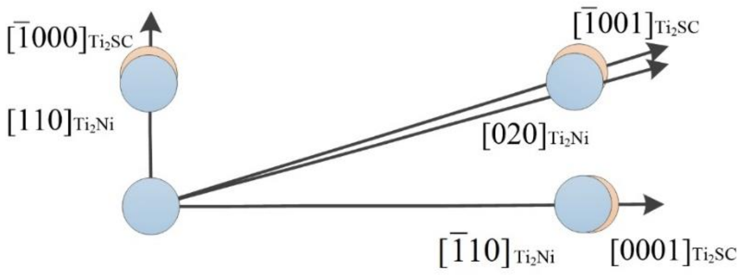
| Matching Face | |||
|---|---|---|---|
| [uvw] Ti2SC | [000] | [001] | [0001] |
| [uvw] Ti2Ni | [110] | [020] | [10] |
| θ (°) | 0 | 0.653 | 0 |
| (Å) | 3.210 | 11.651 | 11.200 |
| (Å) | 3.025 | 11.437 | 11.029 |
| δ (%) | 3.18 | ||
Publisher’s Note: MDPI stays neutral with regard to jurisdictional claims in published maps and institutional affiliations. |
© 2022 by the authors. Licensee MDPI, Basel, Switzerland. This article is an open access article distributed under the terms and conditions of the Creative Commons Attribution (CC BY) license (https://creativecommons.org/licenses/by/4.0/).
Share and Cite
Zhang, T.; Zhen, H.; Liu, T.; Hou, X.; Zhang, Z. Microstructure and Tribological Properties of Lubricating-Reinforcing Laser Cladding Composite Coating with the Ti2SC-Ti2Ni Mosaic Structure Phase. Coatings 2022, 12, 876. https://doi.org/10.3390/coatings12070876
Zhang T, Zhen H, Liu T, Hou X, Zhang Z. Microstructure and Tribological Properties of Lubricating-Reinforcing Laser Cladding Composite Coating with the Ti2SC-Ti2Ni Mosaic Structure Phase. Coatings. 2022; 12(7):876. https://doi.org/10.3390/coatings12070876
Chicago/Turabian StyleZhang, Tiangang, Hao Zhen, Tianxiang Liu, Xiaoyun Hou, and Zhiqiang Zhang. 2022. "Microstructure and Tribological Properties of Lubricating-Reinforcing Laser Cladding Composite Coating with the Ti2SC-Ti2Ni Mosaic Structure Phase" Coatings 12, no. 7: 876. https://doi.org/10.3390/coatings12070876