
Influence of Plasma Torch Power on the Plasma Jet Properties and Microstructure of Alumina Coatings

 ,
,
Abstract
:1. Introduction
2. Materials and Methods
3. Results and Discussion
4. Conclusions
Author Contributions
Funding
Institutional Review Board Statement
Informed Consent Statement
Data Availability Statement
Acknowledgments
Conflicts of Interest
References
- Tamošiūnas, A.; Valatkevičius, P.; Gimžauskaitė, D.; Jeguirim, M.; Mėčius, V.; Aikas, M. Energy recovery from waste glycerol by utilizing thermal water vapor plasma. Environ. Sci. Pollut. Res. 2017, 24, 10030–10040. [Google Scholar] [CrossRef]
- Lv, M.; Zhang, G.; Geng, H. Effect of spraying power on the microstructure and thermoelectric performance of plasma-sprayed higher manganese silicides films. Surf. Coat. Technol. 2019, 363, 152–160. [Google Scholar] [CrossRef]
- Kavaliauskas, Ž.; Kėželis, R.; Milieška, M.; Marcinauskas, L.; Valinčius, V.; Aikas, M.; Uscila, R.; Baltušnikas, A.; Žunda, A. Influence of different plasma spraying methods on the physical properties of YSZ coatings. Surf. Interfaces 2021, 24, 101120. [Google Scholar] [CrossRef]
- Fauchais, P.; Montavon, G. Plasma spraying: From plasma generation to coating structure. Adv. Heat Transf. 2007, 40, 205–344. [Google Scholar]
- Sobhanverdi, R.; Akbari, A. Porosity and microstructural features of plasma-sprayed Yttria stabilized Zirconia thermal barrier coatings. Ceram. Int. 2015, 41, 14517–14528. [Google Scholar] [CrossRef]
- Li, C.J.; Sun, B. Effects of spray parameters on the microstructure and property of Al2O3 coatings sprayed by a low power plasma torch with a novel hollow cathode. Thin Solid Films 2004, 450, 282–289. [Google Scholar] [CrossRef]
- Friis, M.; Persson, C.; Wigren, J. Influence of particle in-flight characteristics on the microstructure of atmospheric plasma sprayed yttria stabilized ZrO2. Surf. Coat. Technol. 2001, 141, 115–127. [Google Scholar] [CrossRef]
- Zhu, J.; Wang, X.; Kou, L.; Zheng, L.; Zhang, H. Prediction of control parameters corresponding to in-flight particles in atmospheric plasma spray employing convolutional neural networks. Surf. Coat. Technol. 2020, 394, 125862. [Google Scholar] [CrossRef]
- Ghara, T.; Bandyopadhyay, P.P. Understanding the role of in-flight particle temperature and velocity on the residual stress depth profile and other mechanical properties of atmospheric plasma sprayed Al2O3 coating. J. Eur. Ceram. Soc. 2022, 42, 4353–4368. [Google Scholar] [CrossRef]
- Vaxevanidis, N.M.; Manolakos, D.E.; Petropoulos, G.P. Surface integrity and tribological behavior of plasma sprayed alumina coatings on steel and aluminum substrates. Tribol. Ind. 2004, 26, 42–47. [Google Scholar]
- Bai, Y.; Zhao, L.; Qu, Y.; Fu, Q.; Wang, Y.; Liu, K.; Tang, J.; Li, B.; Han, Z. Particle in-flight behavior and its influence on the microstructure and properties of supersonic-atmospheric-plasma-sprayed nanostructured thermal barrier coatings. J. Alloys Compd. 2015, 644, 873–882. [Google Scholar] [CrossRef]
- Erickson, L.C.; Hawthorne, H.M.; Troczynski, T. Correlations between microstructural parameters, micromechanical properties and wear resistance of plasma sprayed ceramic coatings. Wear 2001, 250, 569–575. [Google Scholar] [CrossRef]
- Misra, V.C.; Chakravarthy, Y.; Khare, N.; Singh, K.; Ghorui, S. Strongly adherent Al2O3 coating on SS 316L: Optimization of plasma spray parameters and investigation of unique wear resistance behaviour under air and nitrogen environment. Ceram. Int. 2020, 46, 8658–8668. [Google Scholar] [CrossRef]
- Zamani, P.; Valefi, Z. Microstructure, phase composition and mechanical properties of plasma sprayed Al2O3, Cr2O3 and Cr2O3-Al2O3 composite coatings. Surf. Coat. Technol. 2017, 316, 138–145. [Google Scholar] [CrossRef]
- Sabiruddin, K.; Joardar, J.; Bandyopadhyay, P.P. Analysis of phase transformation in plasma sprayed alumina coatings using Rietveld refinement. Surf. Coat. Technol. 2010, 204, 3248–3253. [Google Scholar] [CrossRef]
- Abbas, R.A.; Ajeel, S.A.; Bash, M.A.A.; Kadhim, M.J. Effect of plasma spray distance on the features and hardness reliability of YSZ thermal barrier coating. Mater. Today Proc. 2021, 42, 2553–2560. [Google Scholar] [CrossRef]
- Caliari, F.R.; Miranda, F.S.; Reis, D.A.P.; Filho, G.P.; Charakhovski, L.I.; Essiptchouk, A. Plasma torch for supersonic plasma spray at atmospheric pressure. J. Mater. Process. Technol. 2016, 237, 351–360. [Google Scholar] [CrossRef] [Green Version]
- Xiong, H.B.; Zheng, L.L.; Li, L.; Vaidya, A. Melting and oxidation behavior of in-flight particles in plasma spray process. Int. J. Heat Mass Transf. 2005, 48, 5121–5133. [Google Scholar] [CrossRef]
- Zhang, D.; Zheng, L.; Hu, X.; Zhang, H. Numerical studies of arc plasma generation in single cathode and three-cathode plasma torch and its impact on plasma spraying. Int. J. Heat Mass Transf. 2016, 98, 508–522. [Google Scholar] [CrossRef]
- Gao, Y.; Xu, X.; Yan, Z.; Xin, G. High hardness alumina coatings prepared by low power plasma spraying. Surf. Coat. Technol. 2002, 154, 189–193. [Google Scholar] [CrossRef]
- Marcinauskas, L. Deposition of alumina coatings from nanopowders by plasma spraying. Medziagotyra 2010, 16, 47–51. [Google Scholar]
- Zois, D.; Lekatou, A.; Vardavoulias, M.; Vazdirvanidis, A. Nanostructured alumina coatings manufactured by air plasma spraying: Correlation of properties with the raw powder microstructure. J. Alloys Compd. 2010, 495, 611–616. [Google Scholar] [CrossRef]
- Meierhofer, F.; Hodapp, M.; Achelis, L.; Buss, L.; Noriler, D.; Meier, H.F.; Fritsching, U. Investigation of atomization concepts for large-scale flame spray pyrolysis (FSP). Mater. Und Werkst. 2014, 45, 765–778. [Google Scholar] [CrossRef]
- Bobzin, K.; Ote, M.; Knoch, M.A.; Alkhasli, I.; Heinemann, H. High-Speed Video Analysis of the Process Stability in Plasma Spraying. J. Therm. Spray Technol. 2021, 30, 987–1000. [Google Scholar] [CrossRef]
- Bobzin, K.; Heinemann, H.; O’Brien, A. Capturing the Influence of Jet Fluctuations on Particles in Plasma Spraying. J. Therm. Spray Technol. 2022, 31, 59–69. [Google Scholar] [CrossRef]
- Šuopys, A.; Marcinauskas, L.; Grigaitienė, V.; Kėželis, R.; Aikas, M.; Uscila, R.; Tučkutė, S.; Lelis, M. The effect of heat treatment on the microstructure and phase composition of plasma sprayed Al2O3 and Al2O3-TiO2 coatings for applications in biomass firing plants. Coatings 2021, 11, 1289. [Google Scholar] [CrossRef]
- Brinkiene, K.; Kezelis, R. Effect of alumina addition on the microstructure of plasma sprayed YSZ. J. Eur. Ceram. Soc. 2005, 25, 2181–2184. [Google Scholar] [CrossRef]
- Li, Q.; Hu, J.; Xie, J.; Wang, X.; Yu, C.; Jiang, S.; Liu, Z.; Jiang, X.; Sun, C.; Li, E.; et al. Effect of spray process on dielectric properties of APS-deposited CaO–B2O3–SiO2 glass-ceramic coatings. J. Eur. Ceram. Soc. 2020, 40, 4527–4535. [Google Scholar] [CrossRef]
- Cuglietta, M.; Kesler, O. Relationship between particle and plasma properties and coating characteristics of samaria-doped ceria prepared by atmospheric plasma spraying for use in solid oxide fuel cells. J. Therm. Spray Technol. 2012, 21, 448–460. [Google Scholar] [CrossRef]
- Fauchais, P.; Vardelle, A. Thermal Spray Coatings. In Wiley Encyclopedia of Electrical and Electronics Engineering; John Wiley & Sons, Inc.: Hoboken, NJ, USA, 2007. [Google Scholar]
- Muhammad, M.M.; Jalar, A.; Shamsudin, R.; Isa, M.C. Effect of plasma spray parameters on porosity of fly ash deposited coatings. AIP Conf. Proc. 2014, 1614, 116–121. [Google Scholar]
- Yugeswaran, S.; Selvarajan, V.; Vijay, M.; Ananthapadmanabhan, P.V.; Sreekumar, K.P. Influence of critical plasma spraying parameter (CPSP) on plasma sprayed Alumina-Titania composite coatings. Ceram. Int. 2010, 36, 141–149. [Google Scholar] [CrossRef]
- Jiang, X.-Y.; Hu, J.; Jiang, S.-L.; Wang, X.; Zhang, L.-B.; Li, Q.; Lu, H.-P.; Yin, L.-J.; Xie, J.-L.; Deng, L.-J. Effect of high-enthalpy atmospheric plasma spraying parameters on the mechanical and wear resistant properties of alumina ceramic coatings. Surf. Coat. Technol. 2021, 418, 127193. [Google Scholar] [CrossRef]
- Zhao, D.; Luo, F.; Zhou, W.; Zhu, D. Effect of critical plasma spray parameter on complex permittivity and microstructure by plasma spraying Cr/Al2O3 coatings. Appl. Surf. Sci. 2013, 264, 545–551. [Google Scholar] [CrossRef]
- Yang, E.-J.; Luo, X.-T.; Yang, G.; Li, C.-J.; Takahashi, M.; Kuroda, S.; Kim, K. Impact of deposition temperature on crystalline structure of plasma-sprayed Al2O3 splats revealed by FIB-HRTEM technique. Ceram. Int. 2016, 42, 853–860. [Google Scholar] [CrossRef]


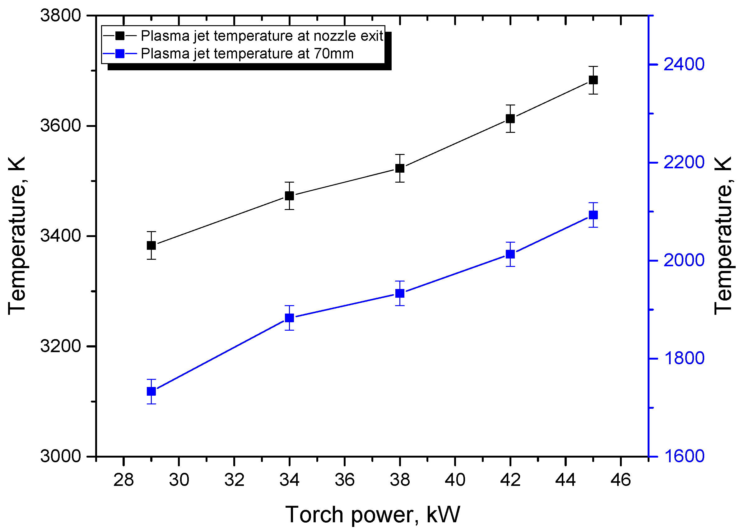
| I, A | P, kW | T1, K | T2, K | T3, K | V1, m/s | V2, m/s |
|---|---|---|---|---|---|---|
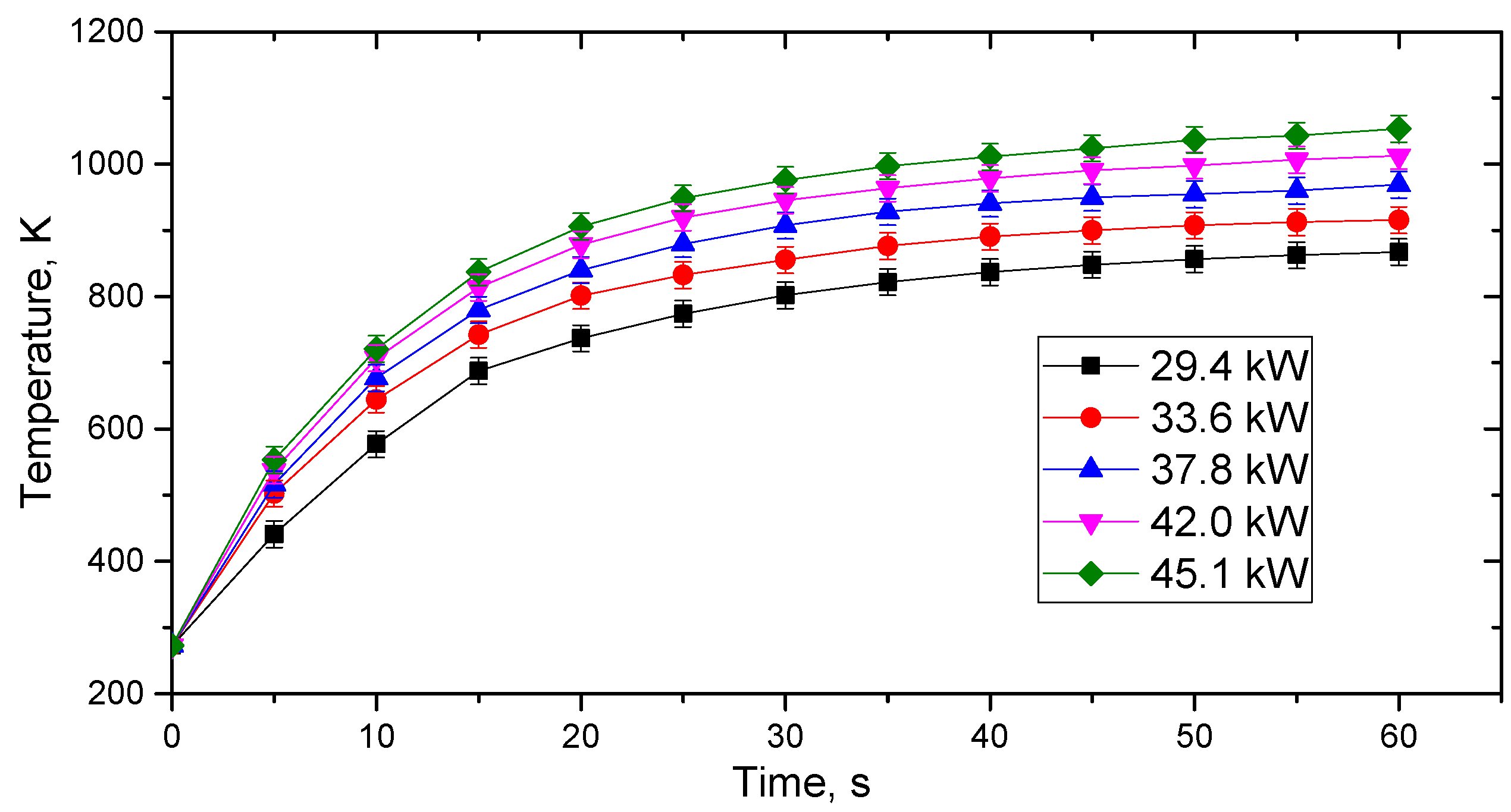
| 140 | 29.4 | 3380 ± 25 | 1730 ± 25 | 870 ± 20 | 965 ± 10 | 380 ± 50 |
| 160 | 33.6 | 3470 ± 25 | 1880 ± 25 | 915 ± 20 | 995 ± 10 | 390 ± 50 |
| 180 | 37.8 | 3520 ± 25 | 1930 ± 25 | 970 ± 20 | 1010 ± 10 | 400 ± 50 |
| 200 | 42.0 | 3610 ± 25 | 2010 ± 25 | 1010 ± 20 | 1040 ± 10 | 420 ± 50 |
| 220 | 45.1 | 3680 ± 25 | 2090 ± 25 | 1050 ± 20 | 1060 ± 10 | 450 ± 50 |
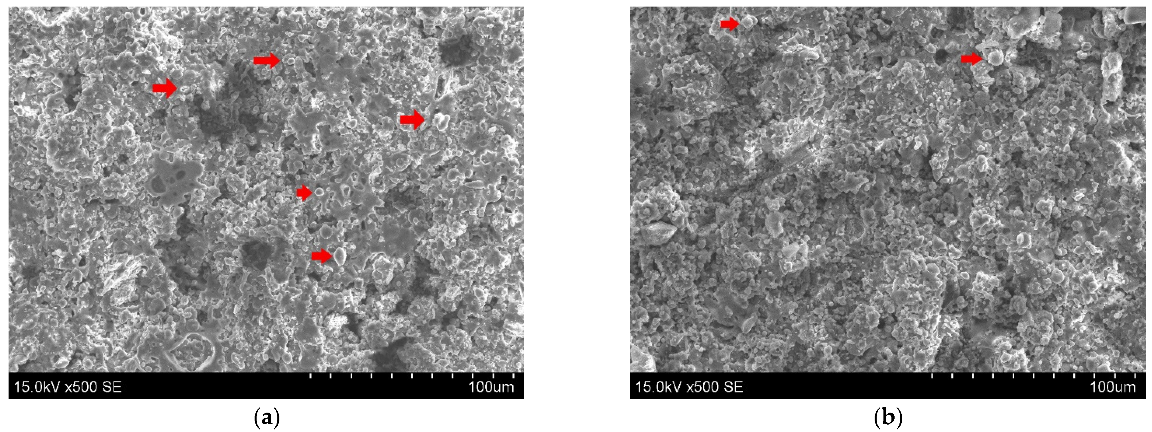
| Torch Input Power, kW | Al, at.% | O, at.% | Rq, µm |
|---|---|---|---|
| 29.4 | 38.7 ± 2 | 61.3 ± 2 | 7.13 |
| 33.6 | 38.9 ± 2 | 61.1 ± 2 | 6.73 |
| 37.8 | 38.5 ± 2 | 61.5 ± 2 | 6.34 |
| 42.0 | 38.4 ± 2 | 61.6 ± 2 | 5.97 |
| 45.1 | 38.8 ± 2 | 61.2 ± 2 | 5.54 |
Publisher’s Note: MDPI stays neutral with regard to jurisdictional claims in published maps and institutional affiliations. |
© 2022 by the authors. Licensee MDPI, Basel, Switzerland. This article is an open access article distributed under the terms and conditions of the Creative Commons Attribution (CC BY) license (https://creativecommons.org/licenses/by/4.0/).
Share and Cite
Šuopys, A.; Grigaitienė, V.; Marcinauskas, L.; Kėželis, R.; Uscila, R.; Aikas, M. Influence of Plasma Torch Power on the Plasma Jet Properties and Microstructure of Alumina Coatings. Coatings 2022, 12, 934. https://doi.org/10.3390/coatings12070934
Šuopys A, Grigaitienė V, Marcinauskas L, Kėželis R, Uscila R, Aikas M. Influence of Plasma Torch Power on the Plasma Jet Properties and Microstructure of Alumina Coatings. Coatings. 2022; 12(7):934. https://doi.org/10.3390/coatings12070934
Chicago/Turabian StyleŠuopys, Airingas, Viktorija Grigaitienė, Liutauras Marcinauskas, Romualdas Kėželis, Rolandas Uscila, and Mindaugas Aikas. 2022. "Influence of Plasma Torch Power on the Plasma Jet Properties and Microstructure of Alumina Coatings" Coatings 12, no. 7: 934. https://doi.org/10.3390/coatings12070934