Abstract
Laser surface texture (LST) technology can be used to increase the adherence of thermal barrier coating (TBC). The primary research method is to conduct a large number of laser experiments to determine the optimal texture parameters. To minimize costs and enhance efficiency, in the current work, five types of circular pit textures were summarized; the plane strain model was established using the transient thermomechanical coupling finite element method; the residual stress field after spraying was used as the prestress field; the influence of different textures on the distribution of the residual stress field after a thermal cycling was analyzed; and the propagation law of cracks in the coating was predicted. The current work focuses on: (1) The two-dimensional cross-sectional morphology of texture; (2) the principal stress perpendicular to the interface (resulting in mode I interface crack) and the shear stress parallel to the interface (resulting in mode II interface crack); (3) texture variables—diameter, depth, and spacing. The results revealed that after thermal cycling, the texture in the ceramic top coat (TC) bore tensile stress of around 350 MPa. Both sides of the pit in the metallic bond coat (BC) bore tensile stress, while the bottom bore compressive stress. Among them, the positive tensile stress of the texture with a sinusoidal section was the greatest, whereas the shear stress was the least. The maximum stress in texture increased as the diameter and depth increased, while the minimum principal stress was obtained by adjusting the spacing among the adjacent textures. The stress level in the coating was reduced by selecting the appropriate texture morphology, and the crack propagation was more complex, that is, it took a longer time before reaching failure, which is expected to improve the life.
1. Introduction
In engineering applications, surface modification technology can give new surface properties, such as hydrophilicity, biocompatibility, adhesion, and so on. Laser surface texture (LST) is considered to be an efficient and economical processing technology, which is suitable for processing irregular surfaces and complex 3D molds, and can achieve very good processing results. It is a hot research direction to apply this technology to the coating to improve the wettability, surface roughness, and bonding strength of the coating. LST can be used to process a series of regular patterns on the surfaces, such as dimples, bumps, grooves, and other microstructures. Therefore, increasing the microstructure can essentially improve the wettability of the solid surfaces, thus promoting the deposition of the thermal sprayed coating. LST can also be used to increase the roughness of the substrate and coating surface, which indicates a larger contact area. The increased contact area can improve the mechanical anchoring between the layers, increasing the bonding strength of the coating.
Meng et al. in 2021 used the Young–Dupre equation to express the relationship between the work of adhesion and the wettability of the substrate. They calculated the average value of the contact angle in the directions parallel and perpendicularly to the grooves, and discovered that the textured substrate surfaces had better surface wettability [1]. To further enhance the adhesion strength or bone tissue fixation in medical implants, Man et al. found that the adhesion strength increases with laser-drilled hole density in a logarithmic manner [2]. The existence of LST will change the initiation and propagation behavior of interlaminar cracks. Son et al. in 2011 compared the sandblasting with and laser surface texturing in two different metal alloys, and found that the porcelain was fractured in a transgranular rather than intergranular fashion at the interface [3]. Wang et al. found that if the roughness of the texture, defined as , was low, the surface cracks propagated vertically to the interface between the ceramic and bonding layers, and turned into transverse cracks, leading to a separation of the ceramic layer; if was larger than 22 , the surface cracks went further down to the interface between the bonding layer and substrate, and propagated horizontally, resulting in the separation of both the ceramic and bonding layers [4]. Laser surface texture increased the contact adhesion area between interfaces, and a large contact area increased the energy release rate at the interface during coating failures. The energy at the interfaces is stored locally due to pattern: pattern morphology, pattern localization and power feed rate are important factors that control the adhesion strength of the thermally sprayed coatings [5]. The texture of the coating surface can resist the delamination or failure stresses caused by a thermal mismatch among the adjacent layers when exposed to high temperature. Dhineshkumar et al. in 2016 set different laser scan speeds, depth, and width on each coating sample; it was found that the laser-textured grooves enhanced the strain tolerance of TBC and provided excellent thermal durability and longer thermal cycle lifetime [6]. The effect of texture depth on the bonding strength of coating has always been the focus of research; the change in depth will directly affect the filling density of the coating spraying process. Tan et al. found that the bonding strength values present an initial increase followed by a decrease when the state of the coatings goes from the full filling state to air entrance in the coatings and partial filling state following the texturing depth [7]. The work of LST is mainly focused on the surface of the metal substrate, while for thermal barrier coating, the interface failure behavior mainly occurs in the forms of cracking, peeling and collapse of the bond coat/top coat layer [8]. Luo et al. meshed patterns at the 8YSZ/NiCoCrAlY bond coat interface by the laser powder deposition (LPD) method; it proved that mesh patterning is effective in impeding the propagation of interface cracks and could dramatically improve the thermal-cycling lifetime of the air–plasma sprayed (APS) TBC [9]. Later, they focused on the geometry parameters of the mesh and the optimal mesh width, height, and spacing length were obtained [10].
There have been many experiments on preparing texture at the coating interface to improve the bonding strength and analyze the crack initiation and propagation behavior [11,12,13], but there are few studies on the influence of texture on the residual stress field of the coating under thermal cycle by using the method of finite element modeling. There have been many studies on the finite element simulation of coatings. The research directions can be summarized as follows: the effects of material properties [14], thermally grown oxide (TGO) [15,16,17] and interface roughness [12,17] on the residual stress of coatings. With the application of LST technology in the coating field more and more widely used, how to obtain the morphology parameters with better performance before the experiment is our focus. In the existing research, the preparation of ideal laser texture on the coating still needs tedious experiments. In order to save time and cost, we proposed to use the finite element method to obtain the optimal texture morphology. Many excellent finite element simulations have considered the influence of the growth of thermally grown oxides on the residual stress in the coating, but our study ignores it because we only consider one thermal cycle.
In this study, the TBC model is established by the finite element method, and laser texture is introduced into the TC/BC interface. This paper focused on the laser surface texture of circular pits, summarizes five cross-section morphologies, considers the prestress field after spraying and the creep effect at high temperature, and analyzes the residual stress field of the TBC model after one thermal cycle load. The results of this study can be used as a reference for laser texture preparation with specific morphology. By adjusting the laser type, output power, scanning speed, and spot diameter, the morphology consistent with the simulation results can be obtained, which can greatly save time and cost.
2. Coupled Transient Thermomechanical Simulations
In a coupled transient thermomechanical finite element analysis (FEA), there are two types of coupling: direct and indirect. The distinction is whether or not the influence of the stress field on the temperature field is taken into account. Given that the influence of a thermal barrier coating’s temperature field on the stress field can be ignored, the temperature field was calculated first, and then imported as a predefined field to obtain the final stress field result.
2.1. The Numerical Model, Boundary Conditions, and Meshing
The schematic view of the numerical model is shown in Figure 1a. The numerical model is composed of the top ceramic layer (TC), the bond coat (BC), and the substrate layer (Sub) based on the structure of the TBC. Gu et al. found that with the increase in the ceramic thickness, the stress gradient became smaller at the BC/Sub interface and became larger at the TC/BC interface [18]. To obtain a clear stress nephogram, we referred to the thickness data in Gu’s article and optimized it. The thickness of the TC, BC, and Sub layers are 0.25 mm, 0.1 mm, and 3 mm, respectively.
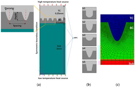
Figure 1.
Schematic of FEM of TBC: (a) geometry of TBC layer, thermal and mechanical boundary conditions, (b) section geometry of laser surface texture, b1: columnar texture, b2: elliptical texture, b3: semicircular texture, b4: sinusoidal texture, b5: trapezoidal texture, (c) mesh generation of TBC, TC: Top Coat, BC: Bond Coat, Sub: Substrate.
The two relevant stresses that should be considered near the TC/BC interface are depicted in Figure 1b. Firstly, the principal stress causes the formation of microcracks along inter-splat boundaries, which are mostly parallel to the x-axis [19]. Secondly, the shear stress leads to interfacial debonding [20]. These two stresses near the TC/BC interface will be examined in this paper.
The FE model is meshed by a quadrilateral element with plane strain approximation and the mesh at the TC/BC interface is refined to ensure accuracy (Figure 1c). To optimize the computation time, symmetrical and periodic boundary conditions are used to represent the periodicity of the model (Figure 1b). The multipoint constraint (MPC) is used to simulate periodic boundary conditions by allowing all the nodes on the rightmost edge to move with the same displacement in the x-direction.
2.2. Section Geometry of Laser Surface Texture
Many surface textures with different morphologies have been developed by laser ablation [2,5,7,13,21]. An Nd: YAG laser working at a wavelength of 1064 nm with a scanning speed of 40 mm/s, laser frequency of 25 kHz and pulse duration of 25 ns integrated with a computer control was used for the generation of surface textures. For the circular pit texture, five cross-sectional morphologies are summarized in Figure 1b. According to the morphological characteristics, they are named columnar texture, elliptical texture, semicircular texture, sinusoidal texture, and trapezoidal texture, respectively. In actual processing, these morphologies can be prepared by adjusting the power, scanning rate, and processing times of the laser [7]. Due to the Gaussian beam generated by the laser, the morphological characteristics of the inverted Gaussian curve (wide at the top and narrow at the bottom) will be formed in the processing process, and these textures are consistent with this characteristic.
We studied the texture of the TC/BC interface for five cycles (Figure 1a) to avoid the influence of boundary conditions. Except for the semicircular texture being different in depth, the other textures are the same in diameter, depth, and spacing (expressed as T-d-h-s), which are T-50-50-90 (unit: ). These three variables will be presented in the following sections.
2.3. Temperature-Dependent Material Properties
All layers of the TBC were assumed to be homogeneous and isotropic. Concerning the works of Bialas [22], the results showed that the effects of plastic and creep of the substrate on the stress level of the coating system were very small. The Sub and TC were treated as linear elastic materials, while the BC was treated as an elastic–plastic material.
The creep properties strongly depend on the temperature. Their effects will be important when the system is at temperatures higher than approximately 600 °C as mentioned by Busso et al. [23]. For the TC and BC layers, the following Norton power-law creep behavior is used [24]:
where is a creep constant (), is the equivalent stress (MPa), and is the creep exponent. The coefficients of and are also temperature-dependent. At the cooling and heating stages during thermal cycling, the time for the temperature held in the range where creep can occur is relatively short. Thus, we only consider the creep at the high-temperature holding stage. For TC, and [25]. For BC, and 2.45 [26].
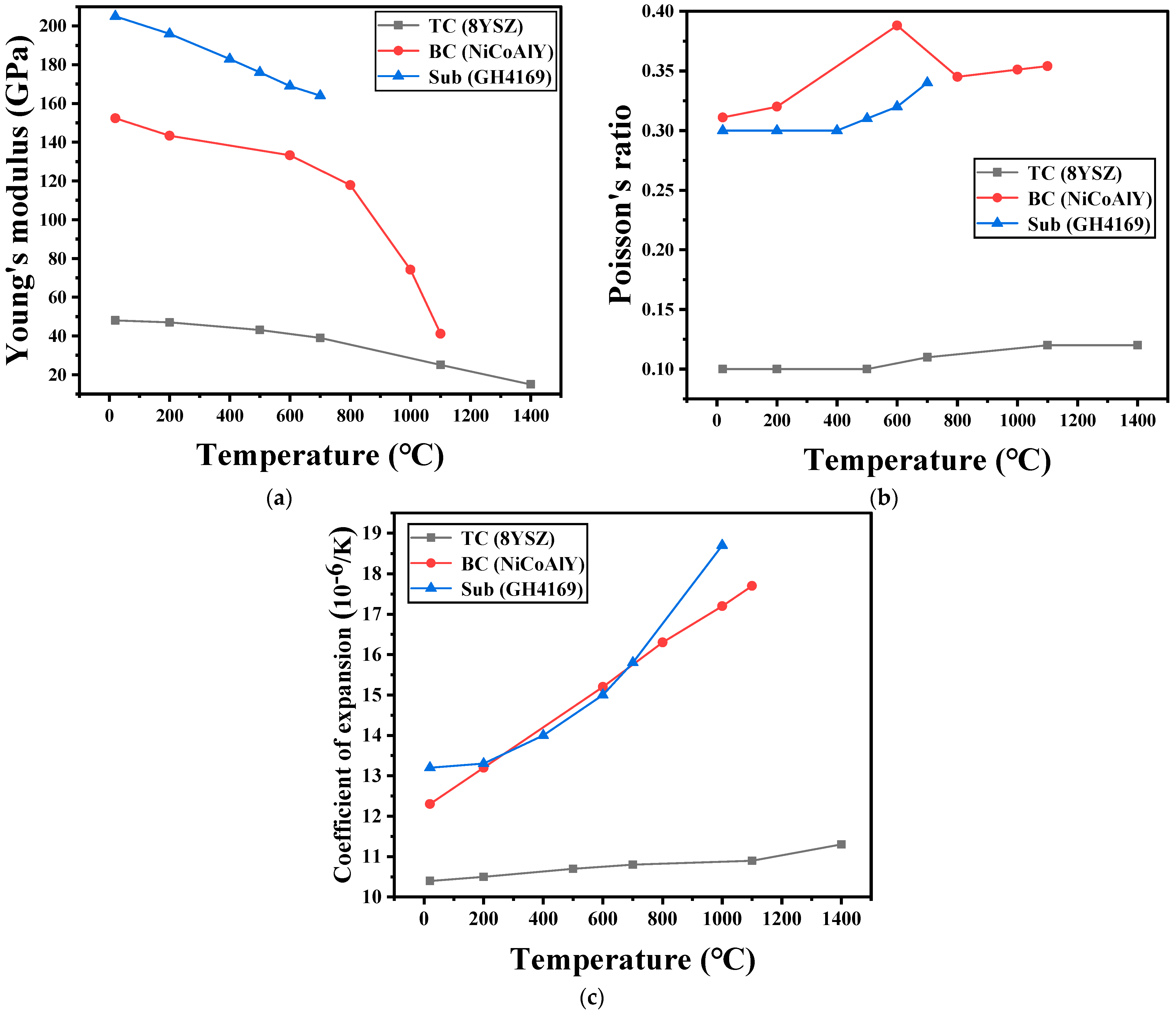
The mechanical properties of all the layers are functions of temperature as listed in Figure 2, Table 1, and Figure 3.
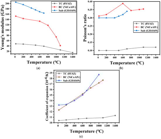
Figure 2.
Temperature-dependent material properties [27]: (a) variation in Young’s modulus with temperature, (b) variation in Poisson’s ratio with temperature, (c) variation in coefficient of thermal expansion with temperature.

Table 1.
Thermal conductivity (λ), specific heat capacity (C), and density (ρ) of TC layer, BC layer, and Sub layer at 20 °C [27].
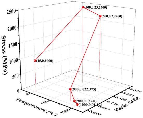
Figure 3.
Plastic parameters of BC [26].
2.4. Thermal Cycling
Our main focus is to study the influence of laser surface texture on the stress field of the coating, and according to the research results of relevant literature [17,28,29,30], the results of multiple thermal cycles on the stress field are relatively small. Therefore, this article mainly covers a single thermal cycling and considers the prestress field after cooling of the coating preparation (natural cooling from 427 °C to 25 °C).
The thermal loads in the model consisting of a high-temperature heat source and low-temperature heat source are shown in Figure 1a. It is assumed that the left and right sides of the model are adiabatic, and natural convection heat transfer occurs outside the TC layer and inside the Sub layer.
For the case of a single thermal cycling, the load consisted of four steps (Figure 4a). Initially, the TBC system was allowed to cool down from 427 °C to room temperature via natural convection, with a convective heat coefficient of 25 . Subsequently, heating from 25 °C to 1200 °C at the high-temperature heat source (25–1000 °C at low-temperature heat source) in 10 min, the top edge of the TC and the bottom edge of the Sub were subjected to a convective heat coefficient of 2000 [31]. This was followed by a dwell-time at 1200 °C at the high-temperature heat source (1000 °C at the low-temperature heat source) for 2 h. In the last step, cooling from 1200 °C to 25 °C (1000 °C to 25 °C) also took 10 min. The TC layer and BC layer creep during the whole stage.
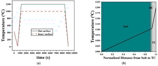
Figure 4.
Thermal cycle used in FEM simulation: (a) four steps of thermal load: cooling of prestress field, heating, holding, and cooling, (b) temperature gradient in TBC at the holding time.
Figure 4b shows the temperature distribution within the TBC system at the holding time. Compared with the Sub layer and BC layer, the temperature drops sharply in the TC layer, which shows the excellent thermal insulation capacity of the TC layer.
3. Results and Discussions
3.1. Distribution of Prestress Field
Because the coating system generates residual stresses during the cooling process after coating completion, many scholars’ assumption that the system was in a stress-free state before thermal cycling [16,28,30,32] was not accurate enough. To ensure that the results are more closely matched to the real situation, the residual stress field generated during the coating cooling process is used as the prestress field in this paper. It is necessary to compare the stress field and prestress field after the whole cycle. As shown in Figure 5, the difference in interface morphology will lead to the change in the stress field. Ignoring the Sub, only the partial coating structure TC/BC is extracted.
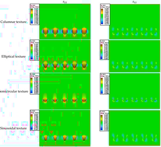
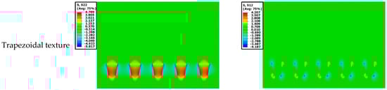
Figure 5.
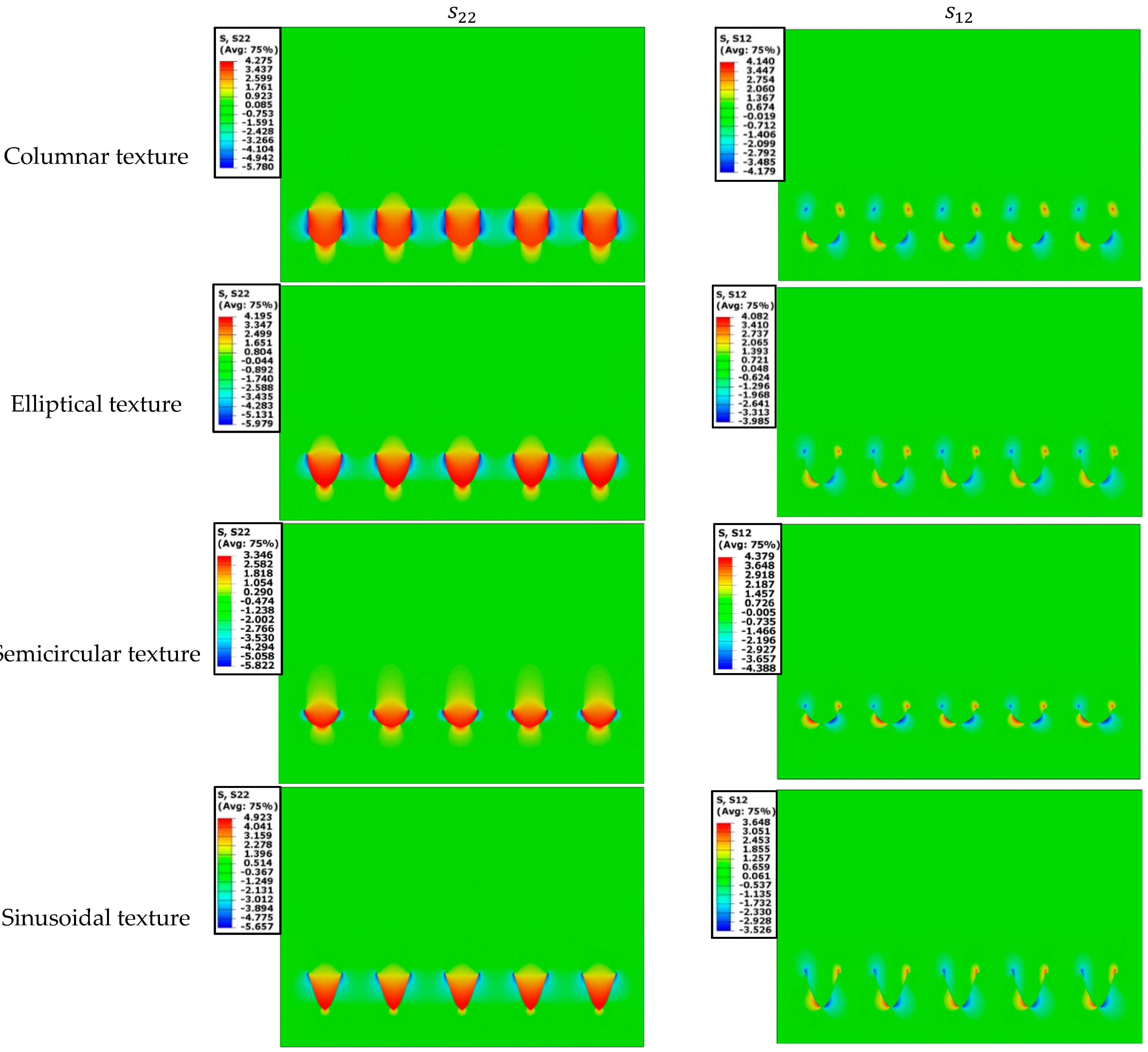
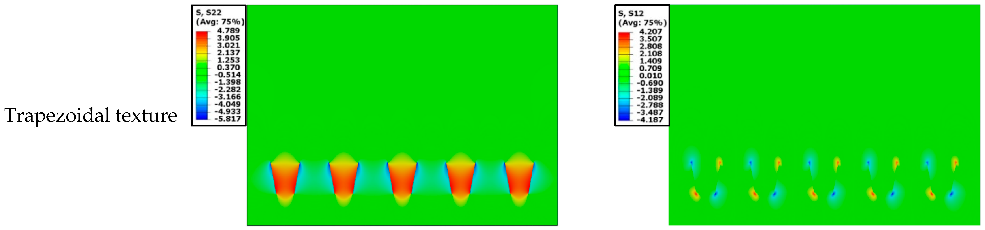
Prestress field distribution of five texture coatings: and .
Observing the prestress field perpendicular to the interface, the texture in the TC layer is subject to positive tensile stress, with a maximum value of about 4 MPa. Except for the semicircular texture being different from the other textures in depth, the maximum tensile stress is 3.346 MPa, and the maximum tensile stress and maximum compressive stress are near the cusp formed by geometric mutation. For the texture in the BC layer, the maximum tensile stress appears at the bottom of the texture, and the maximum compressive stress appears near the cusps at both ends of the texture.
Observing the prestress field : The distribution law of the stress field is the same for all five textures. Positive shear stress exists in the lower left and upper right corners of the texture, while negative shear stress exists in the upper left and lower right, with a maximum value of about 4 MPa.
The results show that for the TC layer processed by laser and cooling to room temperature after spraying, the texture mainly bears tensile stress in the direction perpendicular to the interface, while the two ends of the BC layer bear compressive stress and the bottom is tensile stress. The shear stress of the texture is approximately symmetrical at about the oblique axis in size and direction. By comparing the semicircular texture with other textures, it can be inferred that the change in texture depth will affect the residual stress.
3.2. Stress Field Distribution after a Thermal Cycle
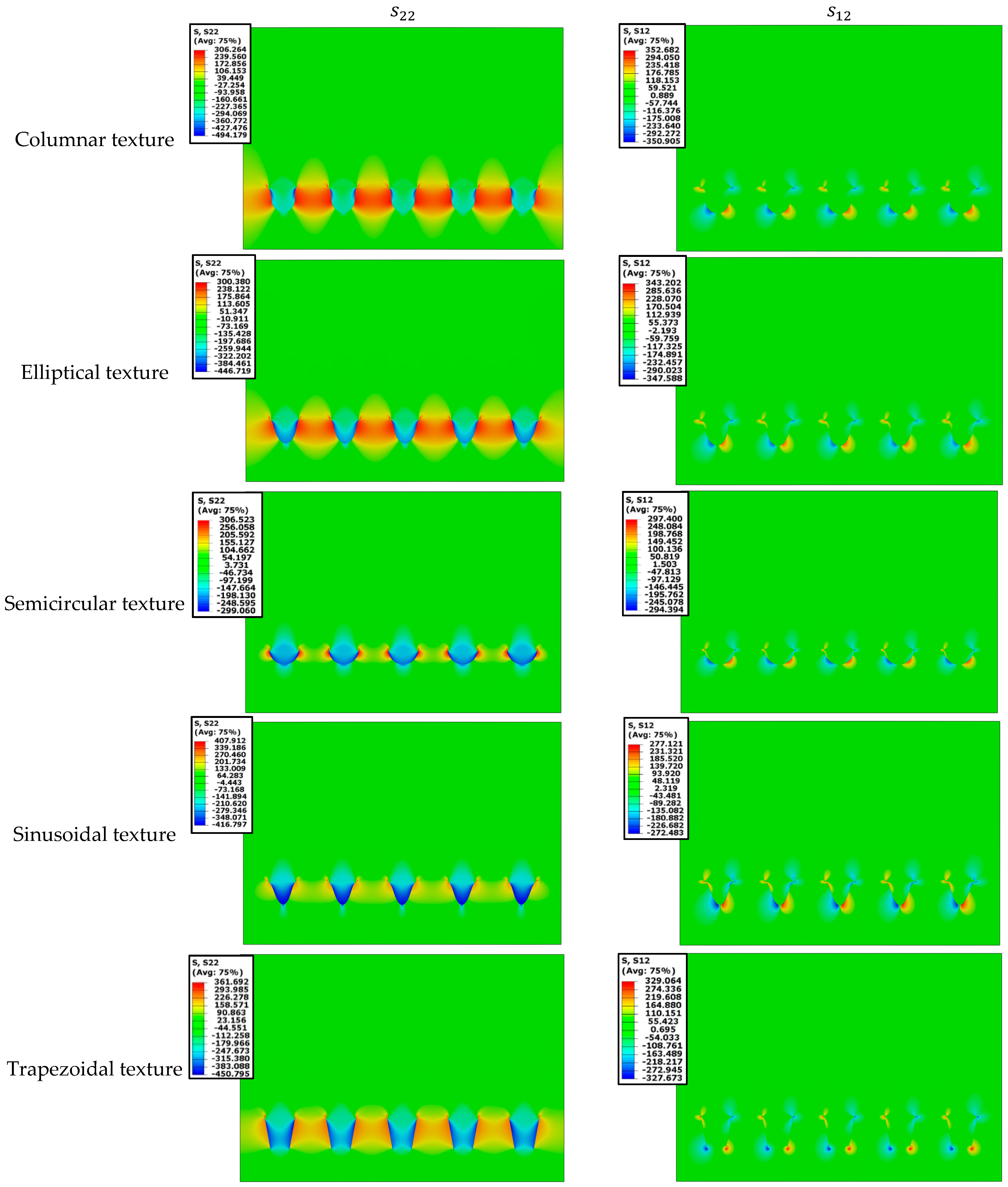
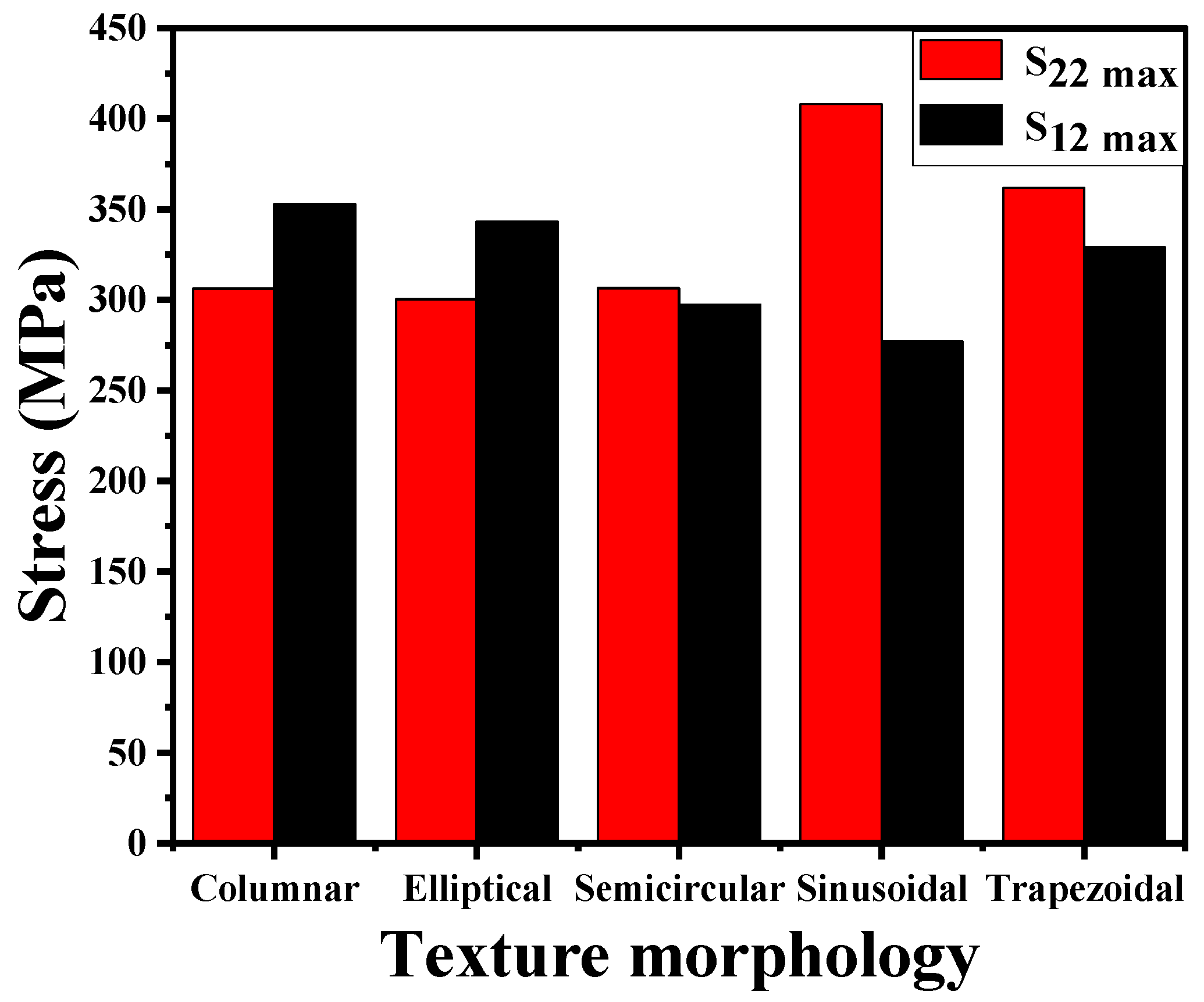
As shown in Figure 6, the stress field near the texture changes significantly after thermal cycling when it is compared to the prestress field. Firstly, the stress increases continuously due to the continuous accumulation of the stress field. Secondly, the stress field distribution at the TC/BC interface differs from that previously observed. Observing the stress field , we find that the texture in the TC layer has shifted from tensile stress to compressive stress; the texture in the BC layer mainly bears tensile stress on both sides and compressive stress on the bottom. The direction of the stress field is opposite to that of the prestress field, and the value has increased. When the effects of texture with different morphologies on the maximum stress and are compared in Figure 7, it is discovered that the coating with sinusoidal texture has the maximum stress and the minimum stress , indicating that sinusoidal texture is most prone to vertical cracks and less prone to transverse cracks.

Figure 6.
Stress field distribution of five texture coatings after one thermal cycle: and .

Figure 7.
Maximum stress and of coatings after one thermal cycling.
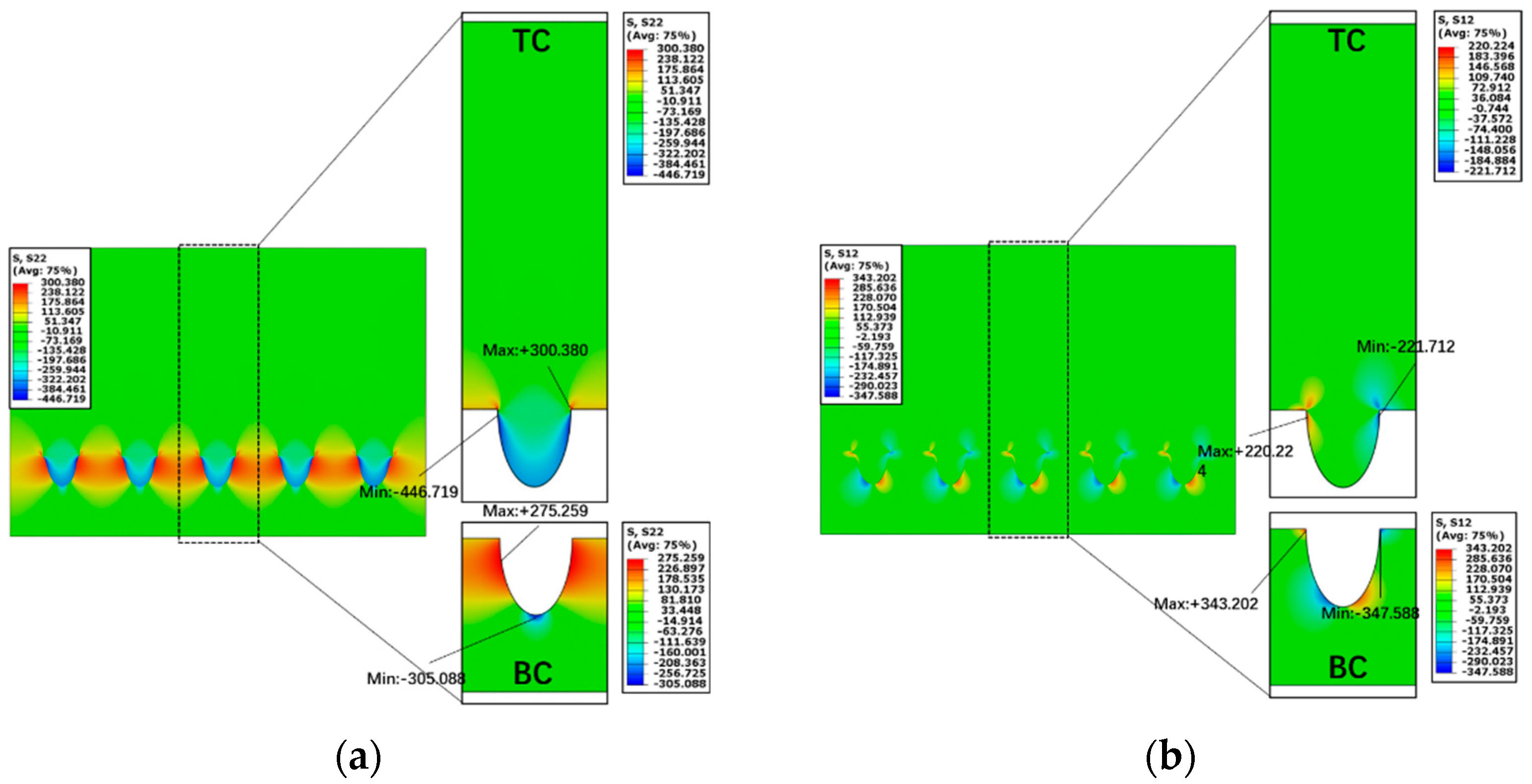
A periodic texture was extracted in order to better analyze the stress field distribution in the TC and BC layers. These five textures all share the same morphological characteristics as described in Section 2.2, so we use the elliptical texture as an example to discuss. The stress field is shown in Figure 8a; the texture in the TC layer bears compressive stress along the edge, while the platform and two cusps bear tensile stress. The maximum tensile stress is 300.380 MPa, and the maximum compressive stress is −446.719 MPa; in the BC layer, the maximum tensile stress near the cusp is 275.259 MPa, and the maximum compressive stress at the bottom of texture is 305.088 MPa. Figure 8b is the stress field . The shear stress is primarily concentrated at the four ends of the texture. In the TC layer, it is natural to believe that the stress concentration will form at the tip of the TC layer. The maximum shear stress in the forward direction is 220.22 MPa, and the maximum shear stress in the reverse direction is −221.712 MPa. Simultaneously, the maximum and minimum shear stress of the BC layer also appear at two cusps, which are 343.202 MPa and −347.588 MPa, respectively.

Figure 8.
Elliptical texture in one cycle: (a) the field, (b) the field.
Due to the different thermophysical properties of the adjacent layers, the texture between the TC layer and BC layer accumulates thermal stress after one thermal cycling. Compared to the TBC system in the prestress field, the stress in the TC layer changes from tensile stress to compressive stress, while the stress in the BC layer changes into tensile stress. The reason for this result is that the coefficient of thermal expansion of the BC layer is larger than that of the TC layer. In the process of temperature change, the deformation of the BC layer is larger than that of the TC layer. After one cycling, the texture in the BC layer expands, bears tensile stress and squeezes the TC layer. Because the maximum and minimum shear stress in the texture appear at the cusp formed by geometric mutation, the laser power should be adjusted in the actual laser preparation of surface texture to make the texture edge smoother, which can reduce stress concentration.
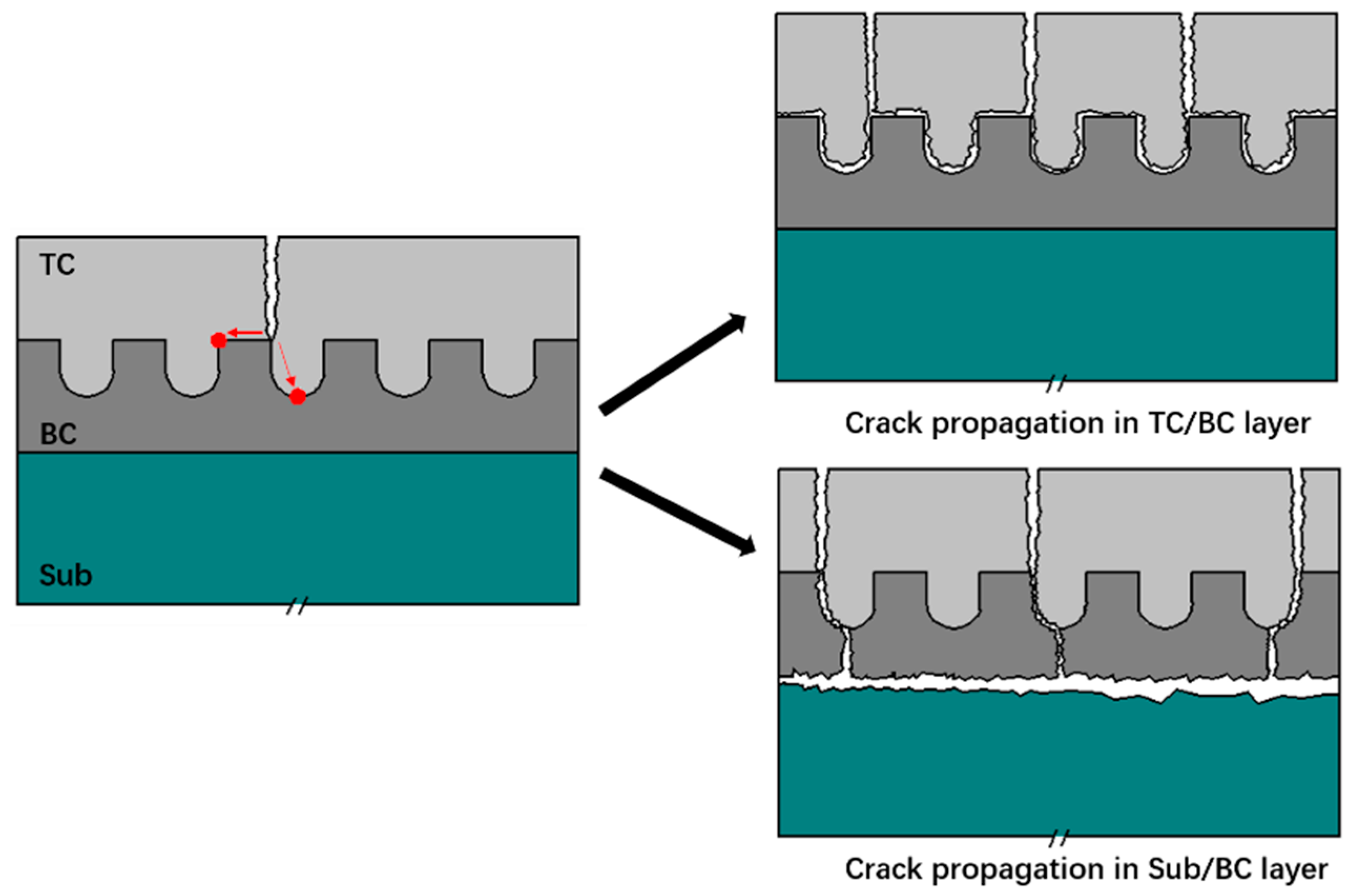
The dominant factor causing crack initiation and propagation at the inner ceramic layer or the bond coat/top coat interface is residual stress in the thermal barrier coating. The crack propagation path is predicted using the residual stress distribution in the coating. The cusp and valley bottom are usually the stress concentration positions, according to research on the stress fields of and . As shown in Figure 9, when the crack initiates on the TC surface and expands inward, it will first expand near the cusp, and then there will be two propagation directions: the other cusp and the valley bottom. The stress concentration at the other cusp is easy to induce the surface cracks with horizontal propagation direction. When multiple cracks are combined in the horizontal direction, the cracking phenomenon in the coating may occur and peel off along the TC/BC interface. Similarly, the stress concentration at the valley bottom makes the surface cracks with a vertical propagation direction easy to induce. The cracks pass through the BC layer to the Sub layer and combine with the interlayer microcracks, causing the coating to crack and spall along the Sub/BC interface.

Figure 9.
Schematic illustration of crack propagation.
3.3. Effect of Texture on Morphology
Circular pit textures with various morphologies can be obtained by varying the properties, power, and processing times of the laser, and cylindrical texture is the most common and easiest to process [4]. In this section, the diameter, depth, and spacing (distribution density) of this texture will be changed to study the distribution of the stress field.
As shown in Figure 10, the influence of the three elements of cylindrical texture (diameter, depth, and spacing) on the two stresses of and is studied by using the control variable method. Considering the situation where cracks are most likely to occur, the maximum stress is mainly compared. The main conclusions are as follows: When the texture diameter is the only variable, the maximum stress of increases with the increase in the diameter, while the maximum stress of is not affected. When the texture depth is the only variable, the maximum stress of and increases with the increase in depth, but the increased range is very small. When the texture spacing is the only variable, the maximum stress of decreases first and then increases with the increase in spacing; when the spacing is 100 , the maximum stress of is the smallest. Likewise, the maximum stress of is unaffected.
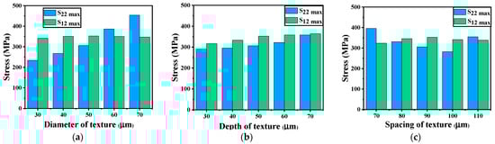
Figure 10.
Effects of diameter, depth, and spacing of columnar texture on two stresses: (a) variable: diameter, depth: 50 μm, spacing: 90 μm, (b) variable: depth, diameter: 50 μm, spacing: 90 μm, (c) variable: spacing, diameter: 50 μm, depth: 50 μm.
In general, the morphological characteristics of texture and distribution density have the greatest influence on coating properties. Without taking into account the effect of actual filling efficiency, increasing the diameter and depth of the texture will increase residual stress, while adjusting the spacing between textures will decrease it.
4. Conclusions
A YSZ-TBC model with laser surface texture (LST) on the TC/BC interface was provided in this paper. According to the section morphology, five types of circular pit texture were identified. Using a coupled transient finite element simulation, the stress near the textures in the TBC after one thermal cycling was estimated. The goal of this study is to see how texture with varied morphologies affects residual stress and to provide some guidelines for laser processing. The following are the key conclusions:
- The presence of texture would subject the TC layer mostly to vertical tensile stress in the prestress field, whereas texture in the BC layer would exhibit compressive stress on both sides and tensile stress at the bottom. The shear stress magnitude and direction were essentially symmetrical about a 45° oblique axis. This indicates that the residual stress distribution in the coating is changed due to the existence of interface texture during the cooling process, so that the stress is uniformly and orderly distributed along the texture.
- Following thermal cycling, the stress value was increased, the direction was contrary to the result of the prestress field, and the geometric mutations were at stress concentration sites. The textures were more prone to vertical cracks than transverse cracks. Cracks could easily propagate along the cusp leading to TC/BC interface failure, and could also easily propagate from the valley of the BC layer to the Sub layer leading to BC/Sub interface failure. The results show that the crack growth in the coating is limited by the interface texture, which will not only affect the initiation of the initial crack, but also change the direction of propagation. In general, the existence of texture will make the crack propagation more complex, and it will take more time before failure, which is expected to improve the service life of the coating.
- The maximum value of the stress was projected to increase with the increase in texture diameter and depth, while modifying texture spacing was expected to decrease. However, the three had no effect on the stress . This demonstrates that the interface texture primarily influences the principal stress in the coating, and choosing the appropriate texture size can reduce the stress level in the coating, whereas relevant studies show that deeper texture can increase the bonding strength between layers, so it must be balanced in practical applications.
The residual stress law of several interface morphologies in the coating was summarized, which provides a basis for the future study of crack propagation. Moreover, before the laser experiment, if the ideal texture morphology is calculated, the rest only needs to adjust the parameters of the laser equipment to make the morphology as close as possible to the simulation results.
Author Contributions
Conceptualization, W.W. and X.Z.; methodology, D.W. and L.W.; validation, X.Z. and S.T.; formal analysis, D.W.; investigation, D.W.; resources, W.W. and S.T.; writing—original draft preparation, D.W.; writing—review and editing, L.W.; visualization, D.W.; supervision, X.Z.; project administration, L.W.; funding acquisition, W.W. All authors have read and agreed to the published version of the manuscript.
Funding
This research was funded by National Natural Science Foundation of China, grant number 52175136.
Institutional Review Board Statement
Not applicable.
Informed Consent Statement
Not applicable.
Data Availability Statement
Data sharing is not applicable to this article.
Conflicts of Interest
The authors declare no conflict of interest.
References
- Meng, X.; Zhang, K.; Guo, X.; Wang, C.; Sun, L. Preparation of micro-textures on cemented carbide substrate surface by plasma-assisted laser machining to enhance the PVD tool coatings adhesion. J. Mater. Process. Technol. 2021, 288, 116870. [Google Scholar] [CrossRef]
- Man, H.C.; Chiu, K.Y.; Guo, X. Laser surface micro-drilling and texturing of metals for improvement of adhesion joint strength. Appl. Surf. Sci. 2010, 256, 3166–3169. [Google Scholar] [CrossRef]
- Son, M.-K.; Choe, H.-C. Evaluation of Interfacial Bonding Strength between Laser Textured Metal Coping and Porcelain. Procedia Eng. 2011, 10, 2286–2291. [Google Scholar] [CrossRef] [Green Version]
- Wang, L.; Di, Y.; Wang, H.; Zhao, Y.; Li, S. On crack evolution with texturization of bonding layer in thermal barrier coating. J. Eur. Ceram. Soc. 2021, 41, 6567–6577. [Google Scholar] [CrossRef]
- Kromer, R.; Costil, S.; Cormier, J.; Courapied, D.; Berthe, L.; Peyre, P.; Boustie, M. Laser surface patterning to enhance adhesion of plasma sprayed coatings. Surf. Coat. Technol. 2015, 278, 171–182. [Google Scholar] [CrossRef]
- Dhineshkumar, S.R.; Duraiselvam, M.; Natarajan, S.; Panwar, S.S.; Jena, T.; Khan, M.A. Enhancement of strain tolerance of functionally graded LaTi2Al9O19 thermal barrier coating through ultra-short pulse based laser texturing. Surf. Coat. Technol. 2016, 304, 263–271. [Google Scholar] [CrossRef]
- Tan, N.; Xing, Z.-G.; Wang, X.-L.; Wang, H.-D.; Jin, G.; Xu, B.-S. Investigation of sprayed particle filling qualities within the texture on the bonding behavior of Ni-based coating. Surf. Coat. Technol. 2017, 330, 131–139. [Google Scholar] [CrossRef]
- Zhang, H.; Liu, Z.; Yang, X.; Xie, H. Interface failure behavior of YSZ thermal barrier coatings during thermal shock. J. Alloy. Compd. 2019, 779, 686–697. [Google Scholar] [CrossRef]
- Luo, L.; Shan, X.; Guo, Y.; Zhao, C.; Wang, X.; Zhao, X.; Guo, F.; Xiao, P. Thermal barrier coatings with interface modified by 3D mesh patterns: Failure analysis and design optimization. J. Am. Ceram. Soc. 2018, 101, 2084–2095. [Google Scholar] [CrossRef] [Green Version]
- Luo, L.; Chen, Y.; Zhou, M.; Shan, X.; Lu, J.; Zhao, X. Progress update on extending the durability of air plasma sprayed thermal barrier coatings. Ceram. Int. 2022, 48, 18021–18034. [Google Scholar] [CrossRef]
- Tang, S.; Wang, C.; Hua, C.; Yang, L.; Wu, Y.; Sun, X.; Song, P.; Huang, B. Surface texture of substrates prepared by femtosecond laser for improving the thermal cycle life of TBCs. Ceram. Int. 2022, 48, 5775–5786. [Google Scholar] [CrossRef]
- Huang, Z.; Ou, J.; Pan, C.; Huang, P.; Si, P.; Zhou, J.; Li, X. Synthesis of PPy–ZnO coatings on laser textured W substrates for ameliorating the adhesion strength of the interface. Appl. Surf. Sci. 2022, 573, 151614. [Google Scholar] [CrossRef]
- Kromer, R.; Cormier, J.; Costil, S.; Courapied, D.; Berthe, L.; Peyre, P. High temperature durability of a bond-coatless plasma-sprayed thermal barrier coating system with laser textured Ni-based single crystal substrate. Surf. Coat. Technol. 2018, 337, 168–176. [Google Scholar] [CrossRef] [Green Version]
- Thakare, J.G.; Pandey, C.; Mulik, R.S.; Mahapatra, M.M. Mechanical property evaluation of carbon nanotubes reinforced plasma sprayed YSZ-alumina composite coating. Ceram. Int. 2018, 44, 6980–6989. [Google Scholar] [CrossRef]
- Busso, E.P.; Qian, Z.Q.; Taylor, M.P.; Evans, H.E. The influence of bondcoat and topcoat mechanical properties on stress development in thermal barrier coating systems. Acta Mater. 2009, 57, 2349–2361. [Google Scholar] [CrossRef]
- Xiao, Y.Q.; Yang, L.; Zhu, W.; Zhou, Y.C.; Pi, Z.P.; Wei, Y.G. Delamination mechanism of thermal barrier coatings induced by thermal cycling and growth stresses. Eng. Fail. Anal. 2021, 121, 105202. [Google Scholar] [CrossRef]
- Wang, L.; Li, Z.; Ding, K.; Deng, C.; Zhang, S.; Zheng, R.; Yang, L.; Lin, X. Effects of TGO growth on the stress distribution and evolution of three-dimensional cylindrical thermal barrier coatings based on finite element simulations. Ceram. Int. 2022, 48, 7864–7875. [Google Scholar] [CrossRef]
- Gu, L.; Fan, X.; Zhao, Y.; Zou, B.; Wang, Y.; Zhao, S.; Cao, X. Influence of ceramic thickness on residual stress and bonding strength for plasma sprayed duplex thermal barrier coating on aluminum alloy. Surf. Coat. Technol. 2012, 206, 4403–4410. [Google Scholar] [CrossRef]
- Weng, W.-X.; Zheng, Z.-H.; Li, Q. Cracking evolution of atmospheric plasma-sprayed YSZ thermal barrier coatings subjected to isothermal heat treatment. Surf. Coat. Technol. 2020, 402, 125924. [Google Scholar] [CrossRef]
- Burov, A.; Fedorova, E. Modeling of interface failure in a thermal barrier coating system on Ni-based superalloys. Eng. Fail. Anal. 2021, 123, 105320. [Google Scholar] [CrossRef]
- Xing, Y.; Wang, X.; Du, Z.; Zhu, Z.; Wu, Z.; Liu, L. Synergistic effect of surface textures and DLC coatings for enhancing friction and wear performances of Si3N4/TiC ceramic. Ceram. Int. 2022, 48, 514–524. [Google Scholar] [CrossRef]
- Białas, M. Finite element analysis of stress distribution in thermal barrier coatings. Surf. Coat. Technol. 2008, 202, 6002–6010. [Google Scholar] [CrossRef]
- Busso, E.; Wright, L.; Evans, H.; McCartney, L.; Saunders, S.; Osgerby, S.; Nunn, J. A physics-based life prediction methodology for thermal barrier coating systems. Acta Mater. 2007, 55, 1491–1503. [Google Scholar] [CrossRef] [Green Version]
- Su, L.; Zhang, W.; Sun, Y.; Wang, T.J. Effect of TGO creep on top-coat cracking induced by cyclic displacement instability in a thermal barrier coating system. Surf. Coat. Technol. 2014, 254, 410–417. [Google Scholar] [CrossRef]
- Rösler, J.; Bäker, M.; Aufzug, K. A parametric study of the stress state of thermal barrier coatings. Acta Mater. 2004, 52, 4809–4817. [Google Scholar] [CrossRef]
- Aktaa, J.; Sfar, K.; Munz, D. Assessment of TBC systems failure mechanisms using a fracture mechanics approach. Acta Mater. 2005, 53, 4399–4413. [Google Scholar] [CrossRef]
- Han, M.; Huang, J.; Chen, S. Behavior and mechanism of the stress buffer effect of the inside ceramic layer to the top ceramic layer in a double-ceramic-layer thermal barrier coating. Ceram. Int. 2014, 40, 2901–2914. [Google Scholar] [CrossRef]
- Asghari, S.; Salimi, M. Finite element simulation of thermal barrier coating performance under thermal cycling. Surf. Coat. Technol. 2010, 205, 2042–2050. [Google Scholar] [CrossRef]
- Liang, L.H.; Liu, X.H.; Chen, L.F.; Wei, Y.G. Effect of ceramic coating thickness on fracture behaviour of coating structure under thermal shock cycles. Ceram. Int. 2022, 48, 11435–11444. [Google Scholar] [CrossRef]
- Mohammadi, M.; Poursaeidi, E.; Torkashvand, K. Finite element analysis of the effect of thermal cycles and ageing on the interface delamination of plasma sprayed thermal barrier coatings. Surf. Coat. Technol. 2019, 375, 243–255. [Google Scholar] [CrossRef]
- Wang, S.; Li, S.; Luo, L.; Zhao, Z.; Du, W.; Sundén, B. A high temperature turbine blade heat transfer multilevel design platform. Numer. Heat Transf. Part A Appl. 2020, 79, 122–145. [Google Scholar] [CrossRef]
- Wang, L.; Deng, C.; Ding, K.; Guo, S.; Li, Z.; Lin, X. Model construction and effect of thermally grown oxide dynamic growth on distribution of thermal barrier coatings. Ceram. Int. 2021, 47, 18385–18396. [Google Scholar] [CrossRef]


Publisher’s Note: MDPI stays neutral with regard to jurisdictional claims in published maps and institutional affiliations. |
© 2022 by the authors. Licensee MDPI, Basel, Switzerland. This article is an open access article distributed under the terms and conditions of the Creative Commons Attribution (CC BY) license (https://creativecommons.org/licenses/by/4.0/).