1. Introduction
Coated indexable cutting inserts made of sintered carbides represent a now commonly used group of cutting tools in the range of manufacturing companies. One of the important factors influencing the machining process is the appropriate choice of cutting tool depending on its properties, such as its own geometry, its change during machining to the state of the cutting edge when changing tools, and the cutting material from which the tool is made and the surface treatment of the cutting edge [
1,
2]. Improper choice of tool or inappropriate use of the tool increases the company’s tool-related costs, which are still taken lightly today [
3]. Related to this phenomenon is the reluctance of manufacturing companies to spend time or money on market research of machine tools, of which there are many applicable variants [
4]. Before starting the research itself, the manufacturer would have to invest in the number of cutting tools they were interested in, and identify and purchase suitable test material (or use material from their own production and thus reduce stocks) [
5]. Paradoxically, the costs of choosing a suitable cutting tool are projected to be completely marginal in the future compared to the costs associated with an inappropriate choice of a specific cutting tool [
6]. Manufacturing companies are increasingly taking this reality into account; however, beyond the financial side of things, they are limited by personnel and research capacities. Therefore, the problem could also be the lack of educated employees able to conduct state research. Manufacturing companies have the same limits in terms of the possibilities of using special measuring devices, which they are reluctant to invest in because of their limited usability for other activities [
7,
8]. From this point of view, laboratory research of phenomena occurring during the machining process has a very significant potential for commercial use in practice [
9].
Sintered carbide is a material composed of two or more phases formed by hard carbide particles in a metal binder, which is prepared by powder metallurgy technology. The production of these machine tools mainly uses Hexagonal tungsten carbide (WC) and cubic titanium carbides (TiC) as well as tantalum (TaC) and niobium (NbC) contained in cobalt (Co) binder, while carbide particles increase strength, hardness and chemical stability [
10,
11,
12]. The dimensions of carbide particles range from 0.1 to 14 μm. Normal binder volume is between 5 and 40% [
13]. In order to increase the cutting performance of sintered carbide tools, their physical and mechanical properties are modified by PVD or CVD vapor deposition [
12,
13,
14]. The combination and quality of the deposited layers, together with the mechanical properties of the carrier material and the geometry of the cutting edge or chip breaker, have a very significant effect on the durability or cutting ability of the machining tool [
2,
15]. The construction of coatings as a multilayer has been known since the 1970s, with the possibility of a gradient design of the application of individual coating layers [
16]. Today, these methods are considered standard and, for example, the problem of cracking is already practically solved by to the reduction of application temperatures [
17]. Very hard but also soft coatings can maintain the already defined cutting geometry of the tools with the aforementioned increase of utility values of cutting tools [
18]. In addition, these are amplified by the recently developed HIPIMS (High Power Impulse Magnetron Sputtering) coating application methods. However, CVD applications are widely used, especially for roughing operation in machining [
19,
20].
During machining, waste material is generated in the form of chips. In order to be able to continuously machine complex workpieces, provided that easy tool change is possible, there must be no obstruction in the tool path and the process fluid flow, leading to the cutting area not being deflected [
21]. The chips have to be generated in certain shapes and according to specific dimensional conditions [
22]. These conditions are especially important when machining on automated machine tools and systems. The types and shapes of chips are dealt with in the ISO 3685 standard, according to which chips are classified into the appropriate categories according to shape and length, as well as according to the direction of departure from the cutting point [
23,
24]. There are also qualitative reasons—a long continuous chip impairs the structure of the machined surface—and quantitative reasons [
25]—the long continuous chip risks winding on the chuck or under the cutting tool—which can lead to tool destruction if it gets between the tool and the workpiece in the cutting area [
26]. On the other hand, very short chips can initiate microcracks on the cutting edge of the tool, leading to premature cutting edge breakage [
27]. The shape and length of the chip depends on the properties of the machined material, the setting of the cutting conditions, the cutting environment, the tool geometry and the properties of the cutting material, especially in the chosen coating protection [
28].
Many studies deal with the optimization of the cutting process by adjusting the size of individual cutting parameters, either by the Taguchi method or by means of variance analysis (ANOVA). These methods are a very enriching field of machining, and due to the inexhaustible number of input parameters, experiments of this type are very valuable factors influencing the machining process [
29]. However, the importance of the shape and length of the chip produced, which influences the above-mentioned qualitative and quantitative factors of the machining process, is often overlooked [
30]. Currently, the importance of the ecological side of waste management is also growing. For example, the ability to form ideal chips of small size during production offers benefits in the form of reduced costs for storage, transfer and recycling of waste material.
2. Experiment
The data presented in this article are part of a long-term research study on cutting tool wear carried out at the Faculty of Mechanical Engineering in cooperation with the mechanical engineering industry and production. The experimental material, used devices and evaluated inserts with selected cutting conditions are described below. Machining was performed on a Doosan Lynx 220LM (Seoul, Korea) CNC lathe, equipped with a Fanuc i-series control system. Tested cylindrical specimens had an initial diameter of 50 mm and a length of 330 mm, a final diameter of 23 mm for system stability. The standard setting of the test workpieces was in the chuck of a CNC lathe with a tailstock lock at the opposite end.
The cutting parameters have been unified to ensure the stability of the machine–tool–workpiece system during machining. The cutting speed
vc for the experiment was chosen in 120 m·s
−1, the depth of cut
ap was set at 1.5 mm and feed rate
f was set to 0.3 mm·ot
−1; this was so the study could approach the cutting conditions used in practice in conventional machining. In the range of these cutting speeds (
vc from 80 to 140 m·s
−1), a speed of 120 m·s
−1 was chosen to approach the more efficient limit of cutting speeds in conventional machining. The values of depth of cut
ap and feed rate
f were determined on the basis of testing when it was necessary to ensure the stability of the cutting process. As a criterion for the completion of the experiment, the durability of the cutting edge for a given exchangeable insert was determined or the achievement of the wear of the major flank
VBmax at level 0.4 mm. This value was chosen based on recommendations used in industrial practice for a limit of flank wear 0.3 to 0.5 mm for coated carbides [
31].
The progression of tool wear as a function of tool time in the frame was observed using an Olympus SZX10 stereomicroscope equipped with a Bresser MicroCam-II digital camera equipped with measuring software. The VBmax measurement took place after each removal of the machined material, i.e., when the process was stopped, the VBD was removed from the tool holder and measured with the micrometric method. The disadvantage of this method is that it is laborious and time consuming. However, this is a reliable method of measuring cutting tool wear, hence it was the chosen procedure. At the same time that VBmax flank wear was evaluated, a sample of the produced chips was evaluated in terms of their shape and size according to ISO 3685, also using an Olympus SZX10 stereomicroscope (Olympus Corporation, Tokyo, Japan) equipped with a Bresser MicroCam-II (Rhede, Germany) digital camera with micrometric measurement method. Each evaluated indexable cutting insert was tested three times to obtain data validity. Together with the evaluation of the chip size, the average number of chips per 100 g of produced chips was evaluated. This gives information about the relationship between the size of the chips produced and their shape. The analysis of waste material in the form of chips is currently not only useful in terms of storage and handling of chips, but also for information on recycling, which is likely to play an even greater role in the management of production companies in the future. Subsequently, the size and extent of wear of the indexable insert was evaluated using a Tescan Vega 3 (Tescan Orsay Holding a.s., Brno, Czech Republic) scanning electron microscope supplemented with a Bruker X-Flash (Billerica, MA, USA) analyzer, which was used to map the elements of the worn cutting tool.
2.1. Experimental Material
As the experimental material, the 1.6582 steel according to EN 10027-2 was chosen. It is a medium-alloy, stainless steel with very good hardenability. This steel is characterized by high values of fatigue limit under static and dynamic stress, and it is not sensitive to overheating. In its refined state, the material retains high toughness (due to the addition of Ni and Cr) and has a favorable tensile strength to yield strength ratio. Generally, it is machined in the soft annealed state, and machinability is difficult due to higher toughness. For the purposes of the experiment, the test material was hardened to 40–44 HRC. This was measured on a CISAM-ERNST AT250 hardness tester. The hardness was measured from the center of the workpiece to the edge area. The hardening of the material to a depth of 15 mm was confirmed, which meets the requirement to finish the hardened mass of the tested material by turning. Steel 1.6582 according to EN 10027-2 is intended for highly stressed parts used in mechanical engineering, especially in the automotive industry, e.g., in gears, pins, eccentrics, shafts, etc. To a certain extent, this material also has damping properties similar to gray cast iron. For this reason, it is used for cutting tool shanks, etc. This material can be used for series production by drawing, extruding or cold pressing [
32]. Therefore, this material has a wide field of application in mechanical engineering and it is for this reason it has been chosen. Last but not least, this material has great economic potential in future due to its price and application possibilities [
33]. The chemical composition of used experimental material after electrospark analysis performed on a Bruker Q4 TASMAN instrument is shown in
Table 1. Chemical analysis confirmed that the tested material complied with the standard; see
Table 2 [
34].
2.2. Investigated Cutting Inserts
For the purpose of the experiment, indexable cutting inserts of the CNMG type according to ISO 6987 from three different manufacturers were used. Hard phase material of these plates consists of sintered carbide type WC and Co binder with the addition of other carbides (Ta, Nb, etc.). It is an ISO group of carbides HC (coated hardmetals) equipped with coatings to reduce wear due to the mechanisms accompanying the machining process. Specifically, these are the following inserts:
CNMG 120408-PM 4315: substrate—HC with applied CVD coating Ti(C, N) + Al
2O
3 + TiN (
Figure 1a). The insert is primarily intended for machining steel; an alternative use is for cast iron.
CNMG 120408E-M GRADE T9315: substrate—HC with applied CVD coating TiCN + Al
2O
3 (
Figure 1b). The insert is primarily intended for machining steel; alternative uses are for cast iron and stainless steel.
CNMG 120408-MP3 WPP10S: substrate—HC with applied CVD coating TiCN + Al
2O
3 (
Figure 1c). The insert is primarily intended for machining steel; an alternative use is for cast iron.
Before starting the experiment, the tested cutting inserts were subjected to EDX/SEM analysis using a Tescan Vega 3 scanning electron microscope supplemented with a Bruker X-Flash analyzer in order to identify the composition of deposited coating layers in the unloaded (unworn) condition. After EDX analysis of the CNMG 120408-PM 4315 indexable cutting insert, the TiN layer was not clearly identified (occurs on the head ridge), and the presence of a 12 µm TiC layer and an 8 µm Al
2O
3 layer can be confirmed with certainty (
Figure 2). EDX analysis confirmed the chemical bonding of the coatings; conversely, the diffusion of elements from the substrate to the coating was not demonstrated by this analysis.
After EDX analysis of the CNMG 120408E-M GRADE T9315 indexable cutting insert, the presence of an 11 µm TiC layer and an 11 µm Al
2O
3 layer can be confirmed (
Figure 3).
EDX analysis of the CNMG 120408-MP3 WPP10S indexable cutting insert confirmed the presence of an 8 µm thick TiC layer and an 11 µm thick Al
2O
3 layer (
Figure 4).
3. Results
At the end of the experiment, the measured values of flank wear VBmax were analyzed and projected onto the timeline based on the tool time in the engagement. In parallel, samples of the produced chips were examined in terms of their length and shape. The number of chips per 100 g of chips was also calculated, which is an analogous value related to their size, respective of length. The worn cutting inserts were then subjected to SEM evaluation and element mapping was also performed using an EDX analyzer.
3.1. Evaluation of Worn Cutting Inserts
The main parameter determining the course of the experiment was the flank wear
VBmax pending on the machining time spent by tool. When the value
VBmax = 0.4 mm was reached, the experiment was stopped for the given cutting insert. During turning, tool wear was continuously measured using an Olympus SZX10 stereomicroscope equipped with a Bresser MicroCam-II digital camera, see
Figure 5.
Figure 6 is a graphical representation of the wear profile for all three cutting inserts. It is obvious that the best result, i.e., the longer machining times, was achieved by the CNMG 120408-PM 4315 cutting insert, with the time of reaching the maximum specified wear rate
T = 25.5 min. It is followed by a CNMG 120408-MP3.
WPP10S board with a time T = 22.5 min. CNMG 120408-MP3 WPP10S cutting inserts have the lowest cutting edge life, the smallest time to reach maximal flank wear, when T = 13.5 min.
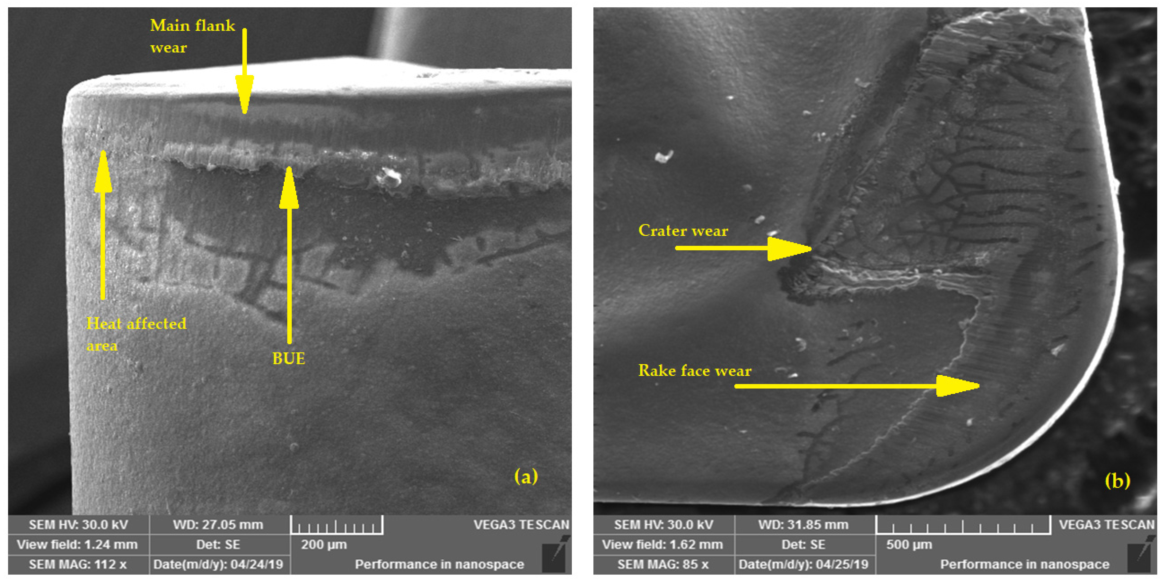
Inserts that had already reached the specified wear rate were subsequently examined using a Tescan Vega 3 electron microscope. SEM analysis confirmed several types of cutting edge wear, the most dominant of which was flank wear. At the same time, there is wear in the form of crater on the face and chipping of the blade or built-up edge (BUE).
The CNMG 120408-PM 4315 insert was worn abrasively on the surface of the main ridge just below the blade; a relatively continuous increase along the cutting edge is evident, see
Figure 7a. The abrasive form of wear was also used on the face of the insert, behind which the relief is copied by a small worn surface in the crater wear form, see
Figure 7b.
EDX analysis showed the extent of wear on the main flank of the CNMG 120408-PM 4315 cutting insert, see
Figure 8. Abrasive wear penetrated to the level of the TiC layer, so the TiN and Al
2O
3 layers on the main flank of the tool were worn. The Fe content in the adhering workpiece material is noticeable. Traces of Si emulate the presence of C, and the analyzer classified it on the basis of similar physical properties.
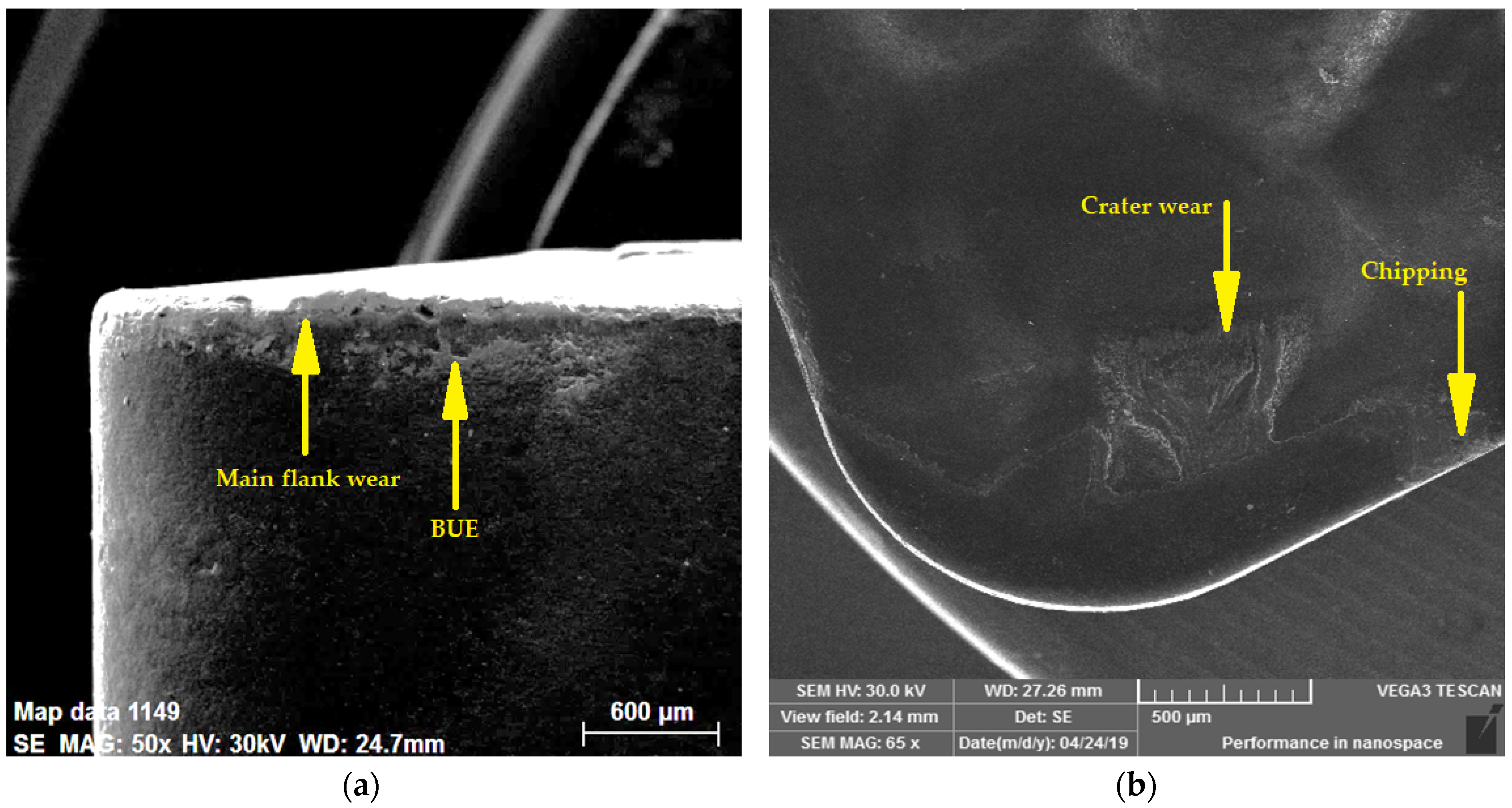
In addition to the abrasive wear of the 120M8E-M GRADE T9315 insert on the main flank, the heat-affected interface in the area of the major flank and the tool corner is visible. There is also a noticeable built-up edge on the main flank of the instrument, see
Figure 9a. There is significant crater wear on the tool face, probably due to the outgoing chip (
Figure 9b).
EDX analysis of the CNMG 120M8E-M GRADE T9315 cutting insert showed the wear of the Al
2O
3 layer to the level of the TiC layer just below the cutting edge, see
Figure 10. The content of the machined material elements in the built-up edge is also evident.
The main type of wear on the CNMG 120408-MP3 WPP10S cutting insert was also abrasive (see
Figure 11a), with the presence of built-up edge. In addition, part of the cutting edge on the main flank was broken out, see
Figure 11b.
Mapping of elements on the worn flank of CNMG 120408-MP3 WPP10S confirms the adhered machined material, see
Figure 12. Wear under the blade has reached the level of the TiC coating layer.
3.2. Evaluation of Produced Chips
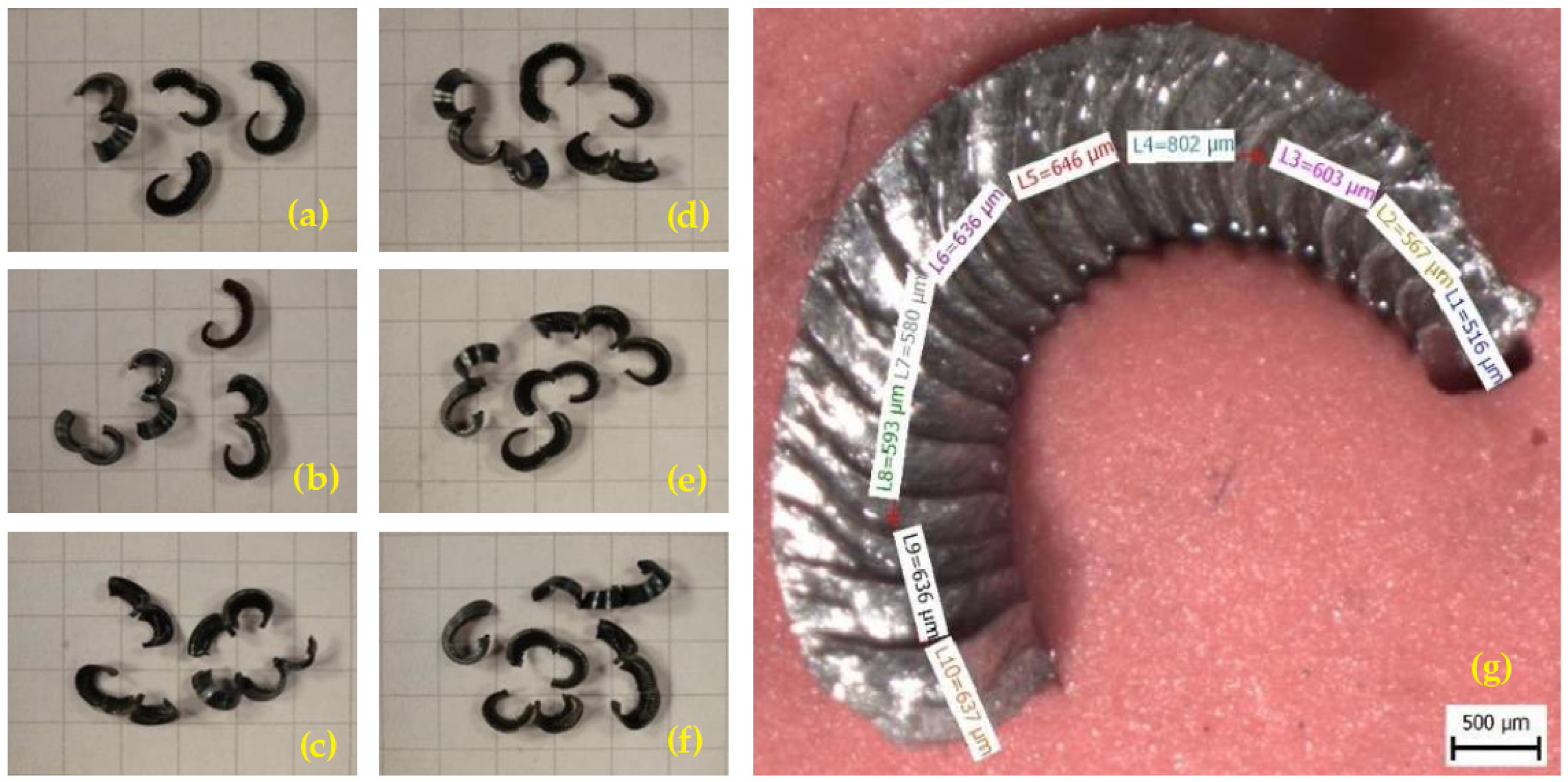
Another part of the experiment was the analysis of produced chips. The collection of samples took place in parallel with the measurement of flank wear
VBmax, see
Section 3.2. For evaluation, an Olympus SZX10 stereomicroscope equipped with a Bresser MicroCam-II digital camera with measurement software was used. The result is chronological documentation of the chip type (see
Figure 13a–f) and analysis of its shape and size according to ISO 3685 (see
Figure 13g). Chip length measurement was performed by the micrometric method using Bresser MicroCamLab II measurement software. The measured chips were selected numbers of four to five pieces so as to best represent the sample of a specific sample.
For the resulting data processing of the length and shape of the chips produced for each insert, see
Table 3. The table also shows the average number of chips per 100 g of chips for each insert. These are analogous values based on the length of the chips produced, which gives a more specific idea of production in terms of possible storage or disposal.
The values in
Table 3 show that the most favorable chip type within the examined group was formed during machining with a CNMG 120408-PM 4315 cutting insert, even in terms of the most constant chip length progression. The average number of chips per 100 g of chips was very similar for both the CNMG 120408-PM 4315 and the CNMG 120408E-M GRADE T9315; however, the second named cutting insert produced a less ideal chip type in a relatively large length range. The least favorable results were achieved when machining the CNMG 120408-MP3 WPP10S cutting insert.
Figure 14 shows the size evolution of the produced chips as a function of the machining time for the individual manufacturers of the monitored inserts. From the data shown, it is clear that the size of the chip produced by the CNMG 120408-PM 4315 cutting insert culminated around a length of 16 mm, but there was no obvious progression in terms of tool wear depending on machining time. A certain increase in chip length was observed in the CNMG 120408E-M GRADE T9315 cutting insert in terms of tool wear. The chip length evolution of the CNMG 120408-MP3 WPP10S cutting insert was increasing from approximately half the tool engagement time, but with a relatively large dimensional peak.
4. Discussion
Based on the measured data and their evaluation, which is described in previous sections, the following facts can be pointed out.
The CNMG 120408-PM 4315 cutting insert with a time T = 25.5 min achieved the best results in terms of cutting edge durability and chip composition depending on machining time. This is contributed to by the fact that, unlike other manufacturers, this producer of CNMG 120408-PM 4315 cutting insert has a TiCN coating on the surfaces of the main and secondary cutting edges. TiCN coating does not have the same hardness as TiC, but it is more thermodynamically stable and shows less tendency to cracking form. EDX analysis did not confirm the mutual diffusion of elements between the individual coating layers and the substrate; therefore, it is a quality deposition of coating layers, chemically connected to each other. A continuous worn surface was created on the main flank of the tool, on which it was possible to identify individual coating layers according to EDX analysis, while there was no loss of tool weight up to the supporting material. An unstable built-up edge can also be identified on the main flank. There is a small amount of wear on the tool face in the form of a crater wear; this can affect the gradual change in the type of chips produced, which split between arch loose and arch connected during the experiment, which are not advantageous from a machining point of view. In terms of chip length, their production with the CNMG 120408-PM 4315 cutting insert was relatively stable, with a total length of around 16 mm.
In terms of wear, the CNMG 120408-MP3 WPP10S cutting insert achieved the second best result. Achieving the specified critical wear VBmax was equal to time T = 22.5 min, which is a relatively small difference compared to the CNMG 120408-PM 4315 cutting insert. The total thickness of the coating layers was the smallest of all the inserts evaluated, while the Al2O3 layer was 8 µm thick and TiC layer was 11 µm thick. In addition to the difference in thickness compared to the CNMG 120408-PM 4315 insert coatings, a TiC coating was used, which has slightly different properties than the TiCN coating. This fact may have contributed to the similarity of the achieved blade life, as with CNMG 120408-PM 4315. Based on SEM/EDX analysis, a break out of the material below the level of the cutting edge was identified, which could result in changes in the chip formation process. The built-up edge was formed both on the surface of the main flank of the tool and on the site of the broken out mass at the level of the cutting edge, which, however, does not necessarily have a negative impact on the machining process. The produced chip had an arch connected shape combined with the largest length within the sample. The difference in temperature stability between the types of TiCN and TiC coatings could affect the change in the type and shape of the chips produced; part of the heat could be distributed differently and thus affect the production of chips. However, this claim would still be subject to further investigation. The difference in coating thickness compared to the previous insert may also have played a role in the formation of the resulting chips. From the point of view of waste management, this is a very disadvantageous type of chip, and in the experiment it is the worst result in terms of chip production.
The CNMG 120408E-M GRADE T9315 cutting insert achieved the shortest tool life, with a time T = 13.5 min. Based on SEM/EDX analysis of the coating layers, TiC coatings with a thickness of 11 µm and Al2O3 with a thickness of 11 µm were identified, which were the largest in terms of thickness within the monitored inserts. It is not entirely clear from the EDX analysis why the result in the shortest time of the specified flank wear VBmax (0.4 mm) was achieved with the most coated insert. Despite the relatively thick layer of Al2O3 coating, there was a thermal effect in the area of the flank and tool corner. The produced chips had an arch connected shape, with a length ranging from 8.9 mm to 31.2 mm and a noticeable increasing trend depending on machining time.
5. Conclusions
Indexable CNMG cutting inserts from three different producers were compared when turning 1.6582 steel according to EN 10027-2, hardened to 40–44 HRC. As part of the comparison, the time of reaching the specified critical flank wear VBmax = 0.4 mm. The durability of the cutting edge depending on machining time and the shape and length of the produced chips according to ISO 3685 under the above-mentioned cutting conditions were evaluated. The results obtained from the experiment made it possible to formulate the following conclusions:
The longest tool life is achieved by a CNMG 120408-PM 4315 cutting insert with a time T = 25.5 min. The CNMG 120408-MP3 WPP10S insert with a time T = 22.5 min achieved an approximately 8% worse result. The worst durability was achieved by the CNMG 120408E-M GRADE T9315 insert with a time T = 13.5 min, i.e., 48% worse durability compared to the CNMG 120408-PM 4315 cutting insert.
The composition and chosen types of coating layers deposition had a fundamental effect on the durability of the inserts.
The initial state of the individual evaluated inserts could also have an effect on the final form of the produced chips in terms of the thickness of the individual coating layers and also in terms of the type of applied coatings.
The nature and continuity of cutting insert wear affected the progression of the length and shape of the produced chips.
The CNMG 120408-PM 4315 cutting insert was worn evenly distributed on the main flank, which led to a stable increase in the length of the chips produced around 16 mm in diameter.
The break out of the CNMG 120408-MP3 WPP10S cutting insert mass below the level of the cutting edge did not have a significant effect on the durability of the insert, but similarly had an effect on the oscillation of the length of the produced chip.
The resulting deposition of CNMG 120408E-M GRADE T9315 cutting insert coatings resulted in a rapid increase of wear and a change in tool geometry; the increase in the length of produced chip grew analogously with an increase in wear on the flank of the tool, with consequent wear in the form of crater wear on the face of the tool.
Author Contributions
Conceptualization, K.Š. and N.N.; methodology, K.Š. and N.N.; validation, N.N. and J.S.; formal analysis, K.Š., N.N., J.S. and D.S.; investigation, K.Š., N.N., J.S. and J.N.; resources, N.N., D.S. and N.V.T.; data curation, K.Š., J.S. and J.N.; writing—original draft preparation, K.Š.; writing—review and editing, K.Š., N.N. and J.S.; visualization, K.Š., N.N. and D.S.; supervision, N.V.T. and N.N.; project administration, K.Š. and J.S.; funding acquisition, J.N., N.N., J.S. and D.S. All authors have read and agreed to the published version of the manuscript.
Funding
This research was funded by Supported by the OP VVV Project Development of new nano and micro coatings on the surface of selected metallic materials—NANOTECH ITI II., Reg. No CZ.02.1.01/0.0/0.0/18_069/0010045.
Institutional Review Board Statement
Not applicable.
Informed Consent Statement
Not applicable.
Data Availability Statement
Not applicable.
Conflicts of Interest
The authors declare no conflict of interest.
Nomenclature
| Symbols and acronyms |
| PVD | physical vapor deposition |
| CVD | chemical vapor deposition |
| BUE | built up edge |
| ap | depth of cut [mm] |
| vc | cutting speed [m·s−1] |
| f | feed rate [mm rev−1] |
| VBmax | maximal flank tool wear [mm] |
| T | tool edge life [min] |
References
- De Vos, P. Realita Současné Výrobní Ekonomiky. Secotools.com. Available online: https://www.secotools.com/article/87163 (accessed on 4 April 2022).
- Denkena, B.; Michaelis, A.; Herrmann, M.; Pötschke, J.; Krödel, A.; Vornberger, A.; Picker, T. Influence of tool material properties on the wear behavior of cemented carbide tools with rounded cutting edges. Wear 2020, 456–457, 203395. Available online: https://linkinghub.elsevier.com/retrieve/pii/S0043164820302386 (accessed on 4 April 2022). [CrossRef]
- Suresh, R.; Basavarajappa, S.; Gaitonde, V.; Samuel, G. Machinability investigations on hardened AISI 4340 steel using coated carbide insert. Int. J. Refract. Met. Hard Mater. 2012, 33, 75–86. [Google Scholar] [CrossRef]
- Astakhov, V.P. The assessment of cutting tool wear. Int. J. Mach. Tools Manuf. 2004, 44, 637–647. Available online: https://linkinghub.elsevier.com/retrieve/pii/S0890695503003122 (accessed on 4 April 2022). [CrossRef]
- Gryč, J.; Nové Obráběcí Nástroje, M.M. Průmyslové Spectrum. 2009, Volume 12. Available online: http://www.mmspektrum.com/clanek/nove-obrabeci-nastroje (accessed on 4 April 2022).
- Siddhpura, A.; Paurobally, R. A review of flank wear prediction methods for tool condition monitoring in a turning process. Int. J. Adv. Manuf. Technol. 2013, 65, 371–393. [Google Scholar] [CrossRef]
- Janásek, A.; Čep, R.; Čepová, L.; Kratochvíl, J.; Vrba, V.; Petřkovská, L. Tool Life Reliability of Indexable Cutting Inserts. Technol. Eng. 2012, 9, 30–34. [Google Scholar] [CrossRef] [Green Version]
- Zhu, D.; Zhang, X.; Ding, H. Tool wear characteristics in machining of nickel-based superalloys. Int. J. Mach. Tools Manuf. 2013, 64, 60–77. [Google Scholar] [CrossRef]
- BI, Z.M.; Wang, L. Optimization of machining processes from the perspective of energy consumption: A case study. J. Manuf. Syst. 2012, 31, 420–428. [Google Scholar] [CrossRef]
- Bunshah, R.F.; Weissmantel, C. (Eds.) Handbook of Hard Coatings; Noyes Publications/William Andrew Publishing, LLC.: Norwich, NY, USA, 2001; p. 550. [Google Scholar]
- Nordin, M.; Larsson, M.; Hogmark, S. Mechanical and tribological properties of multilayered PVD TiN/CrN, TiN/MoN, TiN/NbN, and TiN/TaN coatings on cemented carbide. Surf. Coat. Technol. 1998, 106, 234–241. [Google Scholar] [CrossRef]
- Aneiro, F.M.; Coelho, R.T.; Brandão, L.C. Turning hardened steel using coated carbide at high cutting speeds. J. Braz. Soc. Mech. Sci. Eng. 2008, 30, 104–109. [Google Scholar] [CrossRef] [Green Version]
- Ciftci, I. Machining of austenitic stainless steels using CVD multi-layer coated cemented carbide tools. Tribol. Int. 2006, 39, 565–569. [Google Scholar] [CrossRef]
- Michalski, A.; Sokolowska, A.; Legutko, S. The useful properties of TiNx-Ti coatings deposited onto drills at 500 K using the Reactive Pulse Plasma method. Thin Solid Films 1985, 129, 249–254. [Google Scholar] [CrossRef]
- Hartung, P.D.; Kramer, B.M.; Von Turkovich, B.F. Tool Wear in Titanium Machining. CIRP Ann. 1982, 31, 75–80. [Google Scholar] [CrossRef] [Green Version]
- Rosa, G.C.; Souza, A.J.; Possamai, E.V.; Amorim, H.J.; Neis, P.D. Wear analysis of ultra-fine grain coated carbide tools in hard turning of AISI 420C stainless steel. Wear 2017, 376–377, 172–177. Available online: https://linkinghub.elsevier.com/retrieve/pii (accessed on 18 April 2022). [CrossRef]
- Hoier, P.; Malakizadi, A.; Friebe, S.; Klement, U.; Krajnik, P. Microstructural variations in 316L austenitic stainless steel and their influence on tool wear in machining. Wear 2019, 428–429, 315–327. [Google Scholar] [CrossRef]
- Binder, M.; Klocke, F.; Doebbeler, B. Abrasive wear behavior under metal cutting conditions. Wear 2017, 376–377, 165–171. [Google Scholar] [CrossRef]
- Gaddafee, M.; CHinchanikar, S. Reliability of Coated Carbide Tool During Turning Hardened Steel. IOP Conf. Ser. Mater. Sci. Eng. 2018, 455, 012064. Available online: https://iopscience.iop.org/article/10.1088/1757-899X/455/1/012064 (accessed on 19 April 2022). [CrossRef]
- Mitchell, J. Downsize Your Turning Inserts. In Canadian Metalworkings; Tungaloy Canada: Elgin, IL, USA, 2013; Available online: https://www.canadianmetalworking.com/canadianmetalworking/blog/cuttingtools/downsize-your-turning-inserts (accessed on 19 April 2022).
- Xu, C.; Dou, J.; Chai, Y.; Li, H.; Shi, Z.; Xu, J. The relationships between cutting parameters, tool wear, cutting force and vibration. Adv. Mech. Eng. 2018, 10, 1687814017750434. [Google Scholar]
- Saï, W.B.; Zghal, A.; Ben, A.K. Carbide and ceramic tool life in high speed turning. Int. J. Veh. Des. 2005, 39, 140–153. [Google Scholar] [CrossRef]
- Bhuiyan, M.S.H.; Choudhury, I.A.; Dahari, A.M. Monitoring the tool wear, surface roughness and chip formation occurrences using multiple sensors in turning. J. Manuf. Syst. 2014, 33, 476–487. [Google Scholar] [CrossRef]
- De Vos, P. Příručka Pro Technology—Jak Rozpoznat Správné Utváření Třísek? 2012. Available online: https://www.mmspektrum.com/clanek/prirucka-pro-technology-jak-rozpoznat-spravne-utvareni-trisek.htmlinserts (accessed on 19 April 2022).
- Kumar, J.P.; Kishore, K.P.; Kumar, M.R.; Karthick, S.K.R.; Gowtham, S.V. Experimental investigation on hard turning of AISI 4340 steel using cemented coated carbide insert. IOP Conf. Ser. Mater. Sci. Eng. 2018, 314, 012004. Available online: https://iopscience.iop.org/article/10.1088/1757-899X/314/1/012004 (accessed on 20 April 2022). [CrossRef]
- Aslantas, K.; Ucun, İ.; Çicek, A. Tool life and wear mechanism of coated and uncoated Al2O3/TiCN mixed ceramic tools in turning hardened alloy steel. Wear 2012, 274–275, 442–451. Available online: https://linkinghub.elsevier.com/retrieve/pii/S0043164811006260 (accessed on 20 April 2022). [CrossRef]
- Smith, K.S.; McFarland, J.T.; Tursky, D.A.; Assaid, T.S.; Barkman, W.E.; Babelay, E.F., Jr. Simulating the Effect of Modulated Tool-Path Chip Breaking on Surface Texture and Chip Length; (No. Y/DX-2887); Oak Ridge Y-12 Plant (Y-12): Oak Ridge, TN, USA, 2010. [Google Scholar]
- SANDVIK COROMANT. Příručka Obrábění: Kniha Pro Praktiky; Kudela, M., Ed.; Scientia: Praha, Czech Republic, 1997; Volume 1, p. 857. [Google Scholar]
- Kuntoğlu, M.; Sağlam, A.H. Investigation of progressive tool wear for determining of optimized machining parameters in turning. Measurement 2019, 140, 427–436. [Google Scholar] [CrossRef]
- Leksycki, K.; Feldshtein, E.; Królczyk Legutko, S. On the Chip Shaping and Surface Topography When Finish Cutting 17-4 PH Precipitation-Hardening Stainless Steel under Near-Dry Cutting Conditions. Materials 2020, 13, 2188. [Google Scholar] [CrossRef] [PubMed]
- Sheikh-Ahmad, J.; Davim, J.P. Tool Wear in Machining Processes for Composites. In Machining Technology for Composite Materials; Elsevier: Sawston, UK, 2012; pp. 116–153. ISBN 9780857090300. [Google Scholar]
- Nagode, A.; Resnik, A.; Bizjak, M.; Kosec, G.; Karpe, B.; Budak, I.; Kosec, B.; Zorc, B. Development of banded microstructure in 34CrNiMo6 steel. Metalurgija 2016, 55, 329–332. [Google Scholar]
- Janeková, M.; Koštialiková, D.; Dubec, A.; Burget, M.; Pešlová, F. The Heat Treatment Impact on Material Properties of 34CrNiMo6 Steel. Manuf. Technol. 2018, 18, 912–916. [Google Scholar] [CrossRef]
- EN 10027-2: 2015; Designation Systems for Steels-Part 2: Numerical System. CEN: Brussels, Belgium, 2015.
Figure 1.
Indexable inserts used in tests: (a) CNMG 120408-PM 4315, (b) CNMG 120408E-M GRADE T9315, and (c) CNMG 120408-MP3 WPP10S.
Figure 1.
Indexable inserts used in tests: (a) CNMG 120408-PM 4315, (b) CNMG 120408E-M GRADE T9315, and (c) CNMG 120408-MP3 WPP10S.
Figure 2.
Coating thickness of CNMG 120408-PM 4315 carbide cutting insert.
Figure 2.
Coating thickness of CNMG 120408-PM 4315 carbide cutting insert.
Figure 3.
Coating thickness of CNMG 120408E-M GRADE T9315 carbide cutting insert.
Figure 3.
Coating thickness of CNMG 120408E-M GRADE T9315 carbide cutting insert.
Figure 4.
Coating thickness of CNMG 120408-MP3 WPP10S carbide cutting insert.
Figure 4.
Coating thickness of CNMG 120408-MP3 WPP10S carbide cutting insert.
Figure 5.
Exemplary wear phases of CNMG 120408E-M GRADE T9315 indexable insert depending on the cutting time T [min]: (a) T = 1.5, (b) T = 3, (c) T = 4.5, (d) T = 6, (e) T = 7.5, (f) T = 9, (g) T = 10.5, (h) T = 12, (i) T = 13.5.
Figure 5.
Exemplary wear phases of CNMG 120408E-M GRADE T9315 indexable insert depending on the cutting time T [min]: (a) T = 1.5, (b) T = 3, (c) T = 4.5, (d) T = 6, (e) T = 7.5, (f) T = 9, (g) T = 10.5, (h) T = 12, (i) T = 13.5.
Figure 6.
Flank wear (VBmax) progression of cutting investigated cutting inserts for 1.6582 steel according to EN 10027-2, vc = 120 m·s−1.
Figure 6.
Flank wear (VBmax) progression of cutting investigated cutting inserts for 1.6582 steel according to EN 10027-2, vc = 120 m·s−1.
Figure 7.
SEM analysis of wear of CNMG 120408-PM 4315: (a) main flank view, (b) rake face.
Figure 7.
SEM analysis of wear of CNMG 120408-PM 4315: (a) main flank view, (b) rake face.
Figure 8.
EDX analysis of wear range of CNMG 120408-PM 4315.
Figure 8.
EDX analysis of wear range of CNMG 120408-PM 4315.
Figure 9.
SEM analysis of wear of CNMG 120408E-M GRADE T9315: (a) main flank view, (b) rake face.
Figure 9.
SEM analysis of wear of CNMG 120408E-M GRADE T9315: (a) main flank view, (b) rake face.
Figure 10.
EDX analysis of wear range of CNMG 120408E-M GRADE T9315.
Figure 10.
EDX analysis of wear range of CNMG 120408E-M GRADE T9315.
Figure 11.
SEM analysis of wear of CNMG 120408-MP3 WPP10S: (a) main flank view, (b) rake face.
Figure 11.
SEM analysis of wear of CNMG 120408-MP3 WPP10S: (a) main flank view, (b) rake face.
Figure 12.
EDX analysis of wear range of CNMG 120408-MP3 WPP10S.
Figure 12.
EDX analysis of wear range of CNMG 120408-MP3 WPP10S.
Figure 13.
Exemplary macroscopic chip evaluation of CNMG 120408E-M GRADE T9315 indexable insert depending on the cutting time T [min]: (a) T = 1.5, (b) T = 3, (c) T = 4.5, (d) T = 6, (e) T = 7.5, (f) T = 9, (g) T = 10.5.
Figure 13.
Exemplary macroscopic chip evaluation of CNMG 120408E-M GRADE T9315 indexable insert depending on the cutting time T [min]: (a) T = 1.5, (b) T = 3, (c) T = 4.5, (d) T = 6, (e) T = 7.5, (f) T = 9, (g) T = 10.5.
Figure 14.
Chip size evolution depending on the tool turning time.
Figure 14.
Chip size evolution depending on the tool turning time.
Table 1.
The chemical composition of the 1.6582 steel according to measurements Q4 TASMAN.
Table 1.
The chemical composition of the 1.6582 steel according to measurements Q4 TASMAN.
| Chemical Composition (wt. %) |
|---|
| C | Mn | P | Cr | Mo | S | Ni | Si |
|---|
| 0.342 | 0.57 | max. 0.005 | 1.519 | 0.193 | max. 0.001 | 1.470 | 0.329 |
Table 2.
The chemical composition of the 1.6582 steel according to EN 10027-2.
Table 2.
The chemical composition of the 1.6582 steel according to EN 10027-2.
| Chemical Composition (wt. %) |
|---|
| C | Mn | P | Cr | Mo | S | Ni | Si |
|---|
| 0.30–0.38 | 0.50–0.8 | max. 0.035 | 1.30–1.70 | 0.15–0.30 | max. 0.035 | 1.3–1.7 | max. 0.40 |
Table 3.
Comparison of produced chips for individual cutting inserts.
Table 3.
Comparison of produced chips for individual cutting inserts.
| Investigated Cutting Insert | Chip Type | Chip Length [mm] | Average Number of Chips/100 g of Chips |
|---|
| CNMG 120408-PM 4315 | arch loose/arch connected | 13.7 ÷ 19.7 | 1676 |
| CNMG 120408E-M GRADE T9315 | arch connected | 8.9 ÷ 31.2 | 1753 |
| CNMG 120408-MP3 WPP10S | arch connected | 25.9 ÷ 103.6 | 700 |
| Publisher’s Note: MDPI stays neutral with regard to jurisdictional claims in published maps and institutional affiliations. |
© 2022 by the authors. Licensee MDPI, Basel, Switzerland. This article is an open access article distributed under the terms and conditions of the Creative Commons Attribution (CC BY) license (https://creativecommons.org/licenses/by/4.0/).


 ,
, 


