Abstract
EA4T steel has been widely used in the manufacture of railway axles. Laser cladding remanufacturing technology has been used to repair railway axles, and the failure behaviors of railway axles has been studied. In this work, a class of original FeCrNiMo alloy layers that contain rare-earth elements was successfully fabricated through a laser cladding technique on EA4T steel substrates. The microstructure and elemental distribution of the cladding layers were analyzed through scanning electron microscopy (SEM), transmission electron microscopy (TEM) and electron probe microanalysis (EPMA). Simultaneously, the microhardness, bond strength and fatigue properties of different samples were determined. The results indicated that the phase composition of the cladding layer was mainly martensite. The grains in the cladding layer were gradually refined with an increase in the distance from the interface, and the chemical composition distribution was more uniform. At the same time, the bonding property of the cladding layer and matrix was good, and the fatigue strength of the sample was improved.
1. Introduction
As one of the most important components in railway systems, the axle bears the dynamic load and the weight of the whole vehicle. During the working process of the train, the axle is subjected to variable amplitude loads of axial, radial, shear, bending and torsion characteristics. Therefore, the main damage forms, which determine the total life of railway axles, are rotational bending fatigue and axle pressure surface fretting fatigue. In spite of this, in practice, their premature failure due to cracklike defects (technological or operational) often takes place. Such defects resulting from fatigue mechanisms under operational loads may cause the complete destruction of the axle [1,2,3,4]. D.V. Rudavskyi et al. studied crack propagations in shaft surface defects in axels using surface crack dynamics. The study showed that crack propagation was not only determined by the initial area of the crack itself, but largely by the geometric shape of the crack edge. Relatively small crack-like defects on the surface of a wheelset shaft could reach a critical size in a relatively short time [5]. Damaged railway axles are always rejected, which results in high costs. In recent years, another nontraditional repair process, called laser cladding remanufacturing, has emerged. This process uses damaged and old parts as a matrix for remanufacturing. The method begins with an alloy powder which is heated by a laser and then deposited on the base metal [6,7,8,9]. The alloy powder cladding layer strengthens parts, imparting good mechanical properties, such as heat resistance, corrosion resistance, wear resistance and fatigue durability, and the laser cladding process has little thermal effect on the matrix base. Wenjing Chen et al. [2,10,11] repaired an EA4T axle steel using Fe-Cr-Ni (Fe314) powder and laser cladding technology, and found that under low stress, the fatigue crack growth rate of the repaired sample was lower than that of the original base metal, and the tensile strength was increased. Sun et al. [12] carried out laser cladding on high-performance AISI 4340 steel with iron-based powder and analyzed the microstructure and fatigue properties of the sample after cladding. The results showed that the hardness and brittleness of the heat-affected zone and cladding layer increased while the mechanical properties decreased, but also that the precipitation strengthening of the cladding layer could improve its tensile strength and fatigue life. Guo et al. [13] used laser cladding technology to treat 30CrMnSiA shaft steel with different nickel-based alloy powders. They observed that the fatigue life of specimens was greatly improved after the cladding treatment. Zhang et al. [14] used Fe26 powder to repair a motor spindle by laser cladding and then studied its microstructure and fracture mechanism. Considering the above factors, laser cladding is a suitable way to repair and manufacture components, achieving improved mechanical properties. However, the previous research results of Wenjing Chen et al. [10]. showed that a sample repaired by laser cladding had high strength but poor toughness, especially at the bonding interface.
The addition of rare-earth elements and their oxides can purify, modify and alloy the molten pool, and also effectively improve the microstructure and mechanical and high-temperature properties of the cladding layer. Warren et al. [15] pointed out that the addition of an appropriate amount of lanthanum in AF1400 and HY180 steel sections can reduce the integral number of inclusions and increase the spacing thereof, thus increasing the toughness. Wang et al. [16] conducted comparative experiments on the AISI1045 matrix by laser cladding ni-Fe-Cr alloy powder with different amounts of rare-earth elements. With the addition of these materials, the microstructure of the cladding layer and the secondary dendrite spacing became finer and the impurity content in the cladding layer was reduced. When the concentration of rare-earth elements was too high, these materials became aggregates and formed inclusions. Therefore, as the grain size increases, the secondary dendrite space increases. Considering the above factors, adding rare-earth elements to powder materials is an effective measure for repairing and manufacturing parts with improved mechanical properties.
Although a large body of research exists dedicated repairing EA4T steel by cladding iron-based alloy powder with the laser cladding process, there is no relevant research on increasing the toughness of the bonding zone between the cladding layer and the EA4T steel matrix by adding rare-earth elements to the powder. In this paper, laser cladding remanufacturing technology was used to repair the surface of an EA4T steel axle. We intended to control the size and morphology of the precipitated phase in the cladding layer by adding rare-earth elements to the FeCrNiMo powder, for the first time, to improve the strength and toughness of the interface. The objective of improving the fatigue strength and prolonging the service life of remanufactured samples was achieved. This also provides some theoretical bases for subsequent studies.
2. Experiment
2.1. Materials
EA4T steel is widely applied in railway axles and was used as the base metal for laser cladding [17]. According to the GB/T 228.1-2010 tensile test method for metallic materials and the GB/T 229-2007 charpy pendulum impact test method for metallic materials, the mechanical properties of matrix materials were tested [18,19]. In order to reduce the contingency of the test and improve the accuracy, three samples were tested and the average value was taken. The chemical compositions and properties are shown in Table 1 and Table 2. A Fe-Cr-Ni-Mo alloy steel ingot containing rare-earth elements was prepared by vacuum smelting technology according to a certain proportion of the formula, and then the corresponding self-made alloy powder was prepared by mixing powder making technology. In order to ensure the uniformity of the powder feed and the mechanical properties of the coating, spherical FeCrNiMoRE ferrous metal powder with a particle size range of +45 + 150 μm was used [20]. The morphology of the powder is shown in Figure 1. To remove the water vapor and other adsorbed gases, the cladding material was dried in a vacuum drying box at 150 °C for 40 min.

Table 1.
Chemical composition of materials.
Table 2.
Tensile properties and the U-notch impact energy for the EA4T steel.
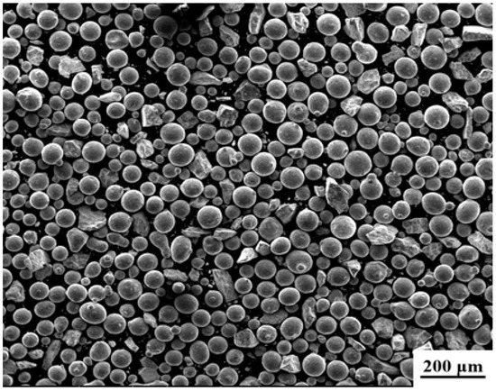
Figure 1.
Appearance of homemade alloy powder.
2.2. Sample Preparation
Before the laser cladding process, rust and oil contamination were removed mechanically. Then, the experimental samples were cleaned using acetone and alcohol. A SISTA-3000 semiconductor laser (Beijing Luhe Feihong Laser Technology Co. Ltd., Beijing, China), KUKA KR-30 robot (Kuka Robotics (Shanghai) Co., Ltd., Shanghai, China) and FHPH-20 powder feeding system (Tianjin Huirui Laser Technology Co., Ltd., Nanjing, China) were used for the laser cladding process. The optimized laser cladding parameters are listed in Table 3. The powder was projected side-synchronously. Argon was used as a protective gas with a constant flow rate to protect the welding pool.
Table 3.
The laser cladding parameters.
2.3. Experimental
To study the morphology of the samples, the cladding layer was etched with a solution of FeCl3 (5 g) + HNO3 (10 mL) + HCl (3 mL) + C2H5OH (87 mL). The microstructure and elemental distribution of the cladding layers were analyzed by scanning electron microscopy (SEM: SN3400, Hitachi Co., Tokyo, Japan), transmission electron microscopy (TEM: JEM-2100F, JEOL Ltd., Tokyo, Japan) and electron probe microanalyzer (EPMA: JXA-8230, JEOL Ltd., Tokyo, Japan). A phase analysis of the cladding layers was performed using X-ray diffraction (XRD: D/max 2550 V, Rigaku Co. (Tokyo, Japan) The step size was 0.03°/s, and the angle was 20–100°) and high-resolution image electron diffraction (TEM: JEM-2100F).
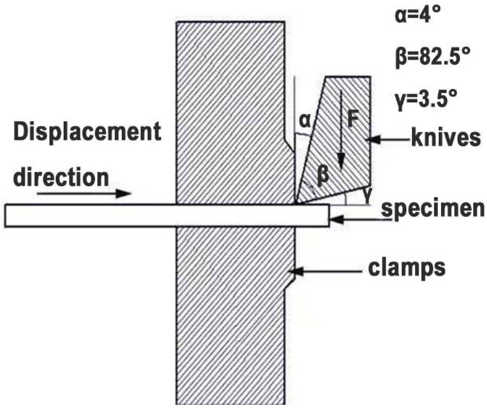
A Vickers hardness tester (HVS-1000, Shanghai Mi-testing Technology Co., Ltd., Shanghai, China) was used to measure the microhardness of the sample based on the ASTM E384-11e1 standard [21]. Because the thickness of cladding layer was relatively small, if the load was too large, the hardness value would be affected, but if the load was too small, the error would be large. Therefore, in the hardness test, the loading force was 1.96 N, which was maintained for 20 s. To study the interface characteristics of the samples after cladding, a microshear test was used to evaluate the connective strength between the base material and the cladding layer. The principle of the microshear test is shown in Figure 2 [22]. The feed rate of the shear specimen was advanced by a screw micrometer that was fixed at the end. Hence, the shear spacing could be precisely set at 0.01 mm. The shear rate was set to 1 mm/min. According to the GB/T4337-2015 “Metal-Fatigue Test-Rotating rod Bending Method” [23], rotating bending fatigue tests were carried out on a PQ-6 rotary bending fatigue testing machine for the matrix and the sample after cladding. The fatigue test was carried out in room temperature air for 107 cycles. The rotating bending sample is shown in Figure 3.
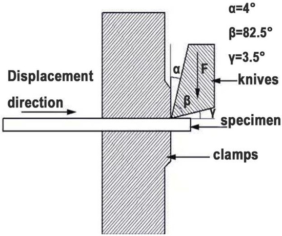
Figure 2.
Schematic diagram of the microshear.
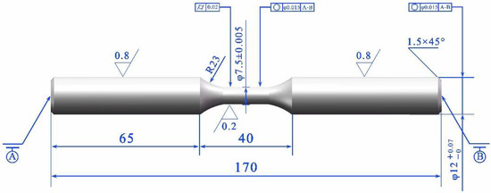
Figure 3.
Size of the rotating bending fatigue samples (dimensions in mm).
3. Results and Discussion
3.1. Microstructure of the FeCrNiMoRE Cladding Layer
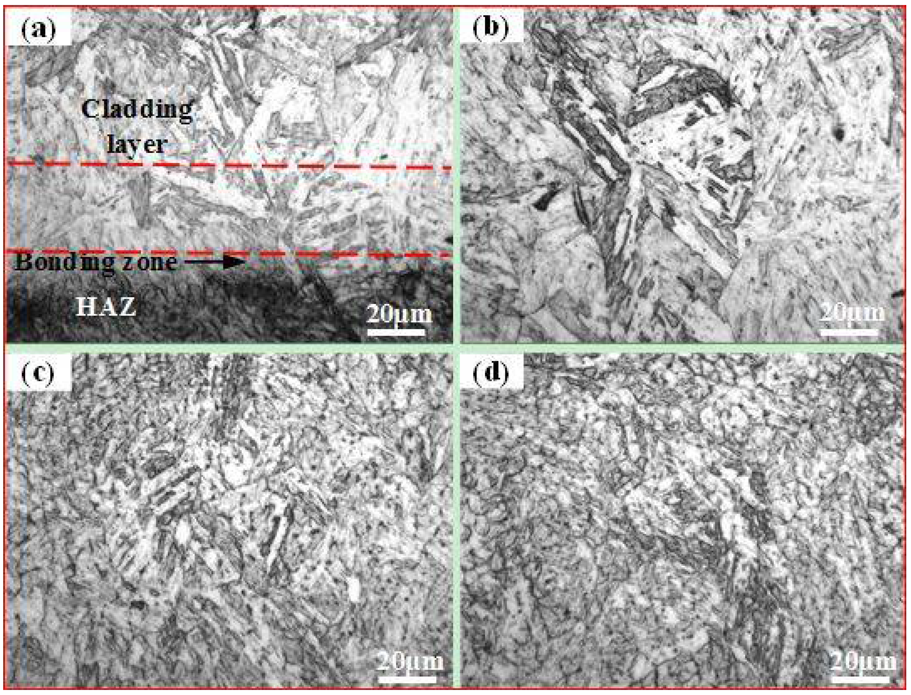
Figure 4 shows the microstructures of the FeCrNiMoRE cladding layer. The microstructure of the cladding layer was mainly martensite. As exemplified in Figure 4a, the crystal order of the matrix and the cladding layer was still maintained at the bonding interface. With the increase in the distance from the interface, the grains in the cladding layer were gradually refined, and equiaxed crystals formed at the top of the cladding zone (Figure 4b–d). This occurred mainly because some compounds formed by the rare-earth elements themselves can also become nucleating particles, increasing the number of nucleations and thus refining the grain size of the cladding layer [24,25]. In addition, Figure 4d shows that there was a sufficiently long undercooling zone in the laser pool, and fine equiaxed crystals formed at the top of the pool.
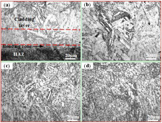
Figure 4.
Microstructure of FeCrNiMoRE cladding layer: (a) interface; (b) the bottom region; (c) the middle region; (d) the top region.
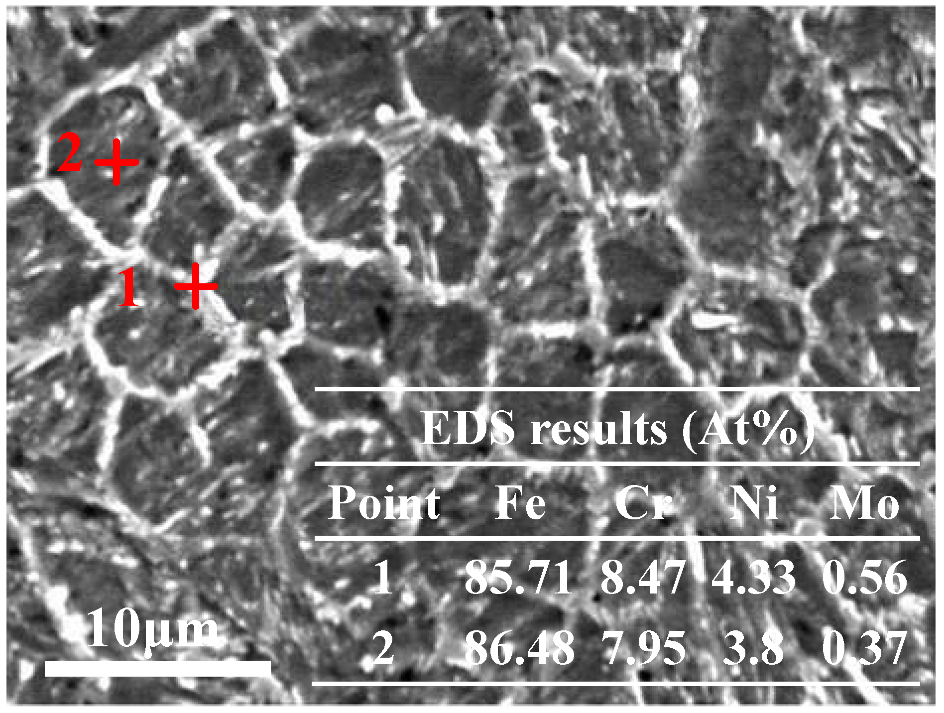
Figure 5 EDS (Energy Dispersive Spectrometer) analysis shows the composition analysis of the cladding layer top. Figure 4 shows that a small amount of segregation occurred at the grain boundary of the cladding layer, where the degree of segregation was very small. The contents of Mo, Cr and Ni in the grain boundary were slightly increased compared with those in the interior of the grains. This may have been because Mo and Cr have a strong affinity with C, so they can form stable carbides and precipitate along grain boundaries. As an austenite-forming element, Ni exhibited a small amount of segregation at the grain boundary. The reason for this phenomenon may be that laser cladding is a rapid solidification process, i.e., it reduces the diffusion rate of C and slows the formation rate of austenite.
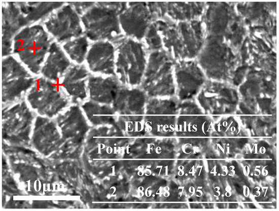
Figure 5.
EDS analysis of structure of the cladding layer top.
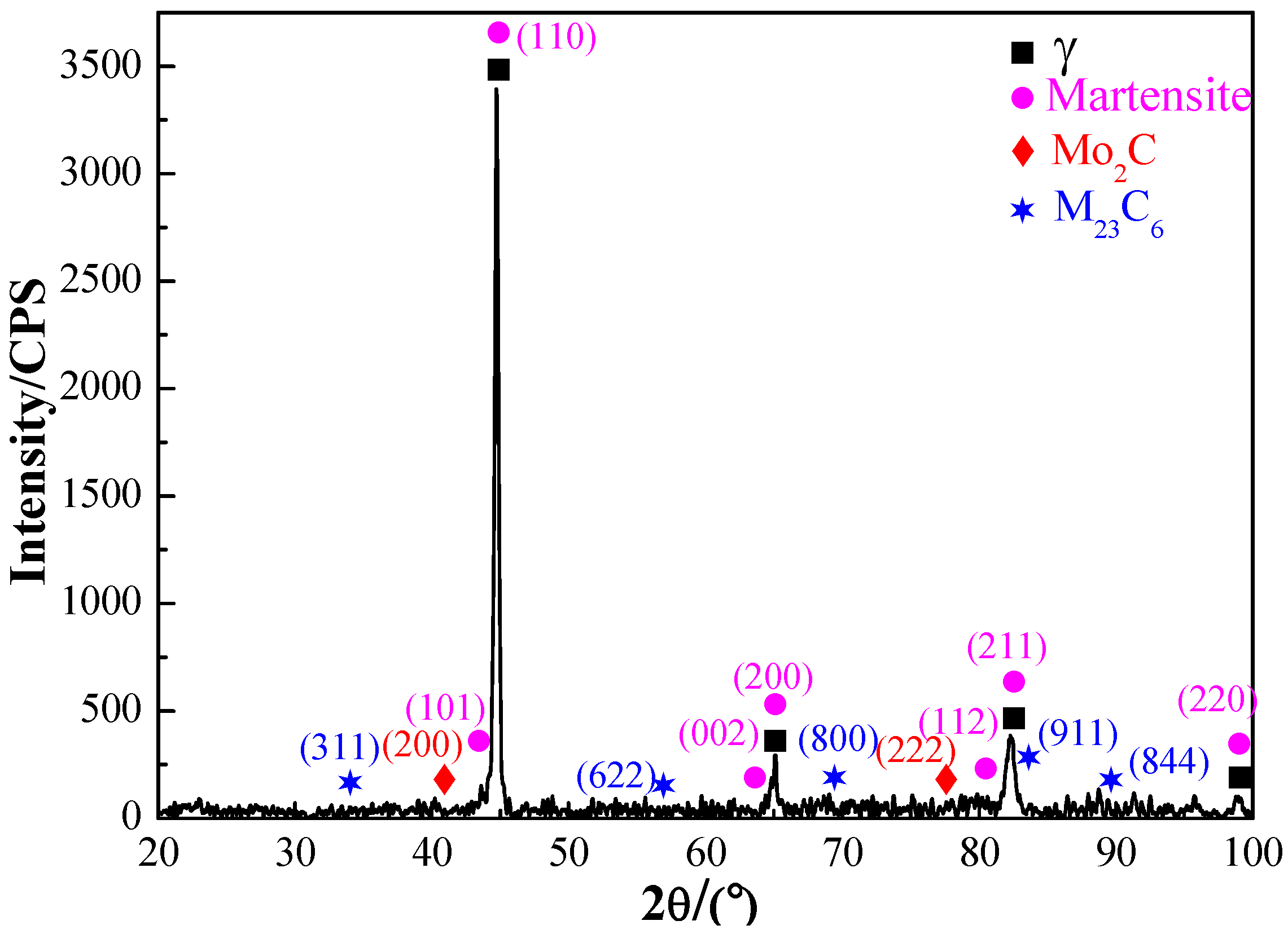
Figure 6 shows the XRD phase analysis results of the cladding layer. It can be seen from the diagram that the phase of the cladding layer was mainly composed of martensite (PDF#44-1290), retained austenite (PDF#34-0396), and small amounts of Mo2C (PDF#15-0457) and M23C6 (PDF#25-0405). When the temperature is lower than the critical temperature of austenite transformation, austenite is in an unstable thermodynamic state and will transform under certain conditions. After a large amount of martensite was formed, the retained austenite was in an irregular shape between the martensite and was squeezed in all directions to prevent the retained austenite from continuing the transformation; as such, it finally localized between martensite bundles [26]. In addition, Cr and Mo are strong carbides forming elements, and began to precipitate a small amount of stable Cr23C6 and Mo2C carbides along the austenite grain boundary. As such, the austenite content gradually decreased. Except for a large amount of Mo dissolved in the Cr23C6 carbides, some other elements (such as Fe, Ni, etc.) can replace Cr atoms in Cr23C6 and finally form complex M23C6 carbides and precipitate along the grain boundaries of Cr23C6 [27,28].

Figure 6.
XRD of FeCrNiMoRE cladding layer.
Figure 7 shows the SEM and EPMA diagram of the laser cladding layer section. The significant color differences of C, Cr and Mo between branches and dendrites indicated that their compositions were significantly different, and there were new phases precipitated in the cladding layer. Enriched C, Cr and Mo were found at the grain boundary of the cladding zone by EPMA analysis. The enrichment of Cr was significantly higher than that of Mo, indicating that Cr and Mo carbides were precipitated at the grain boundary. It was further verified that the precipitated phase of the cladding layer was mainly composed of Mo2C and Cr23C6 carbide.
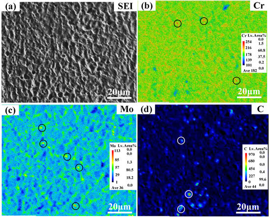
Figure 7.
SEM image and microzone composition analysis of cladding layer (EPMA). (a) SEI Fig.; (b) Distribution of Cr; (c) Distribution of Mo; (d) Distribution of C.
TEM images of the FeCrNiMoRE layer are shown in Figure 8. It can be seen that there was obvious lath martensite in the cladding layer, which contained high-density dislocations [12,29,30]. Figure 8b was obtained from the ellipse marked as (b) in Figure 8a. The high-resolution images along the [001] crystal orientation illustrated that the precipitated phases with large lattice constants were uniformly distributed inside the cladding layer (Figure 8b). The degree of mismatch between the precipitated phase and matrix caused a large strain, strengthening the cladding layer.
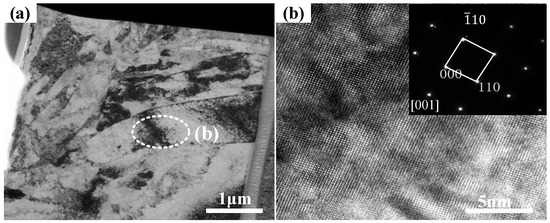
Figure 8.
TEM of FeCrNiMoRE cladding layer: (a) Microstructure of the cladding layer; (b) High resolution image along the (001) direction.
Figure 9 shows a SEM image of the cladding layer. It indicates that there were a small number of irregular inclusions in the cladding layer and precipitated phase. An EDS analysis of the inclusions showed enrichment of Ce, La, O and S. Because La and Ce can form stable compounds with O and S, the Gibbs free energy of the Ce2O2S reaction formula was minimal, preferentially forming in the interdendrite and inhibiting the formation and coarsening of chromium and molybdenum carbide.
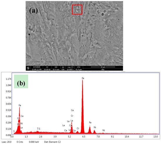
Figure 9.
(a) The structure of the cladding layer; (b) EDS result for the corresponding area in (a).
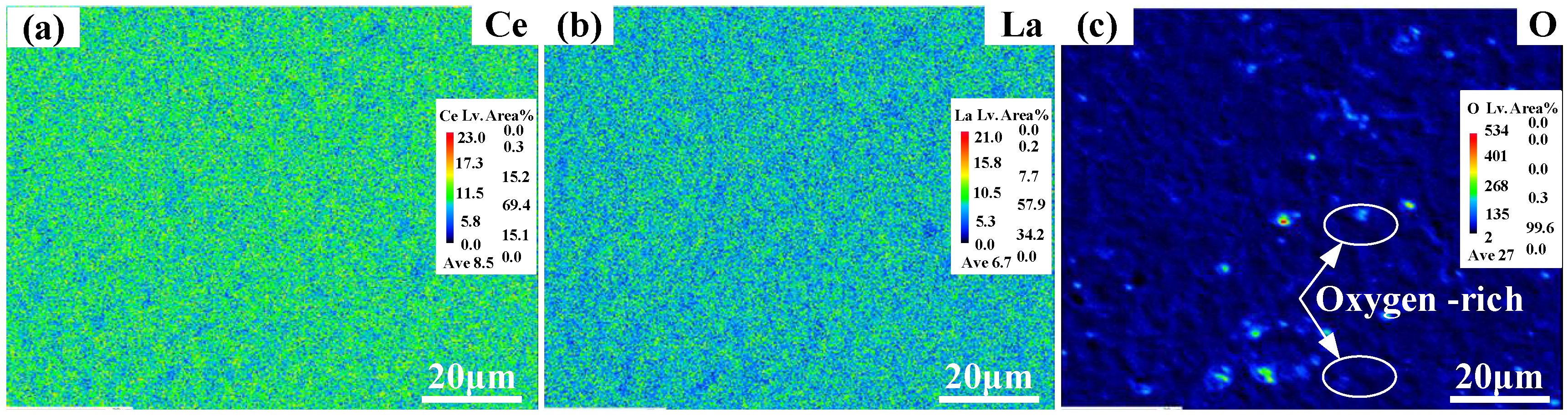
Electron probe microanalysis (EPMA) was used to analyze the distribution of Ce, La and O in the cladding layer; the mapping results are presented in Figure 10. Ce and La were evenly distributed in the cladding layer (Figure 10a,b), while O was enriched at the grain boundaries (Figure 10c). During the laser cladding process, Ce and La react metallurgically with O and S in the molten pool to form oxides, sulfides and sulfur oxides of rare-earth metals.

Figure 10.
Element distribution and phase analysis of the cladding layer. (a) Distribution of Ce; (b) Distribution of La; (c) Distribution of O.
By calculating the thermodynamics of Ce and La versus those of O and S, it was expected that Ce2O3, CeS, Ce2O2S, Ce2S3, Ce3S4, La2O3, LaS and La2S3 would be precipitated from the molten pool at 1600 K [31]. Given that FeCrNiMoRE exists in the melting state during the preparation and cladding stages, when rare-earth oxides, sulfides and sulfur oxides exist in the laser bath, the activity coefficient of each compound was α = 0 [32,33]. According to Equation (1), Ce, O and S can generate Ce2O2S at 3500 K, so Ce2O2S preferentially precipitates at the grain boundaries. Therefore, the addition of rare-earth elements can remove impurity elements in the cladding layer and provide more nucleation sites for the solidification process, which is beneficial to the refinement of crystal grains.
where is the change in the standard Gibbs free energy of the equation, T is the absolute temperature (K), R is the molar gas constant (and its value is 8.314 K)−1, fi is the activity coefficient of component i in solution, and Xi is the mass percentage concentration of component i. The calculation results of lnfi are shown in Table 4.
Table 4.
Calculation results of the activity coefficients of the alloying elements.
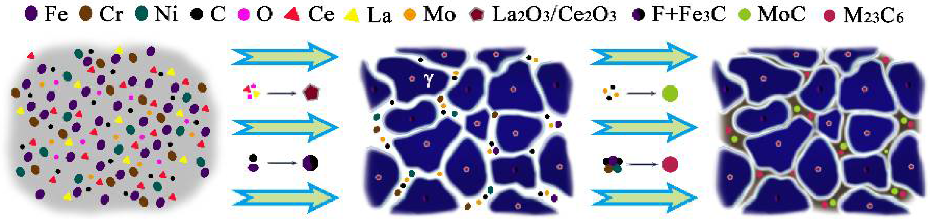
The formation mechanism of FeCrNiMoRE cladding layers can be described by the model in Figure 11. In the FeCrNiMoRE samples, Ce and La reacted with oxygen and sulfur in the melt to purify the melt. The precipitated rare-earth compounds acted as austenite nucleation sites (Figure 11). The increase in nucleation sites was beneficial for the refinement of the grains, thereby improving the performance of the cladding layer.
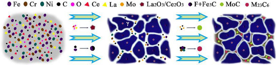
Figure 11.
Schematic diagram of different cladding layer.
3.2. Microhardness Test
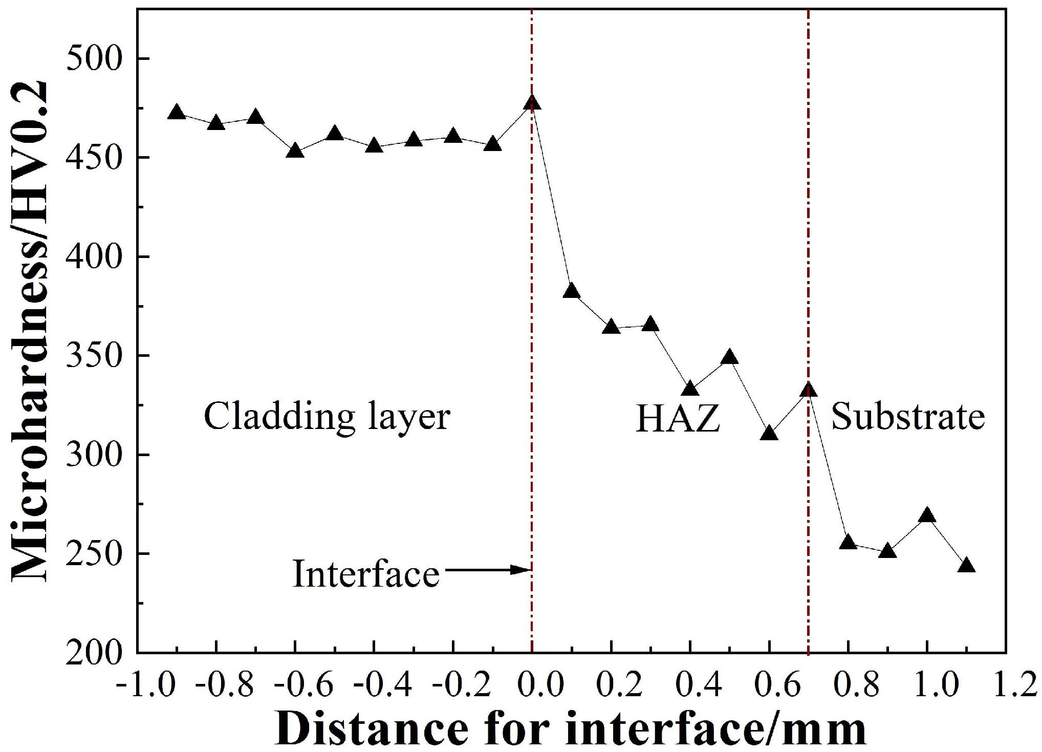
Figure 12 shows the distribution curves of microhardness. Figure 11 shows that the microhardness of the whole cladding zone was between 450 and 480Hv0.2, and the distribution of the microhardness was relatively uniform. In the heat-affected zone, the microhardness was between 350 and 400Hv0.2. Compared with that of the cladding zone and the heat-affected zone, the microhardness of the substrate was the lowest. The microhardness distribution was closely related to the microstructure. The microstructure of the cladding zone was mainly martensite and carbide precipitates. At the bottom of the cladding zone, the microhardness was relatively low due to the coarse martensite grains, while at the surface, the microhardness was relatively high due to the appearance of fine equal axis grains. In the coarser grain area of the heat-affected zone, the microstructure was mainly coarse lath martensite, and in the fine-grained area, it was mainly martensite and a small amount of sorbite, so the microhardness was relatively reduced. The matrix structure had a sorbite structure and a small amount of massive ferrite. Because the sorbite was composed of polygonal ferrite and granular cementite, its plasticity and toughness were good, but its microhardness was relatively low. As a result, the microhardness of this structure was the lowest observed in this study.
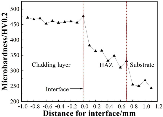
Figure 12.
Microhardness distribution curve of repair sample.
3.3. Microshear Test
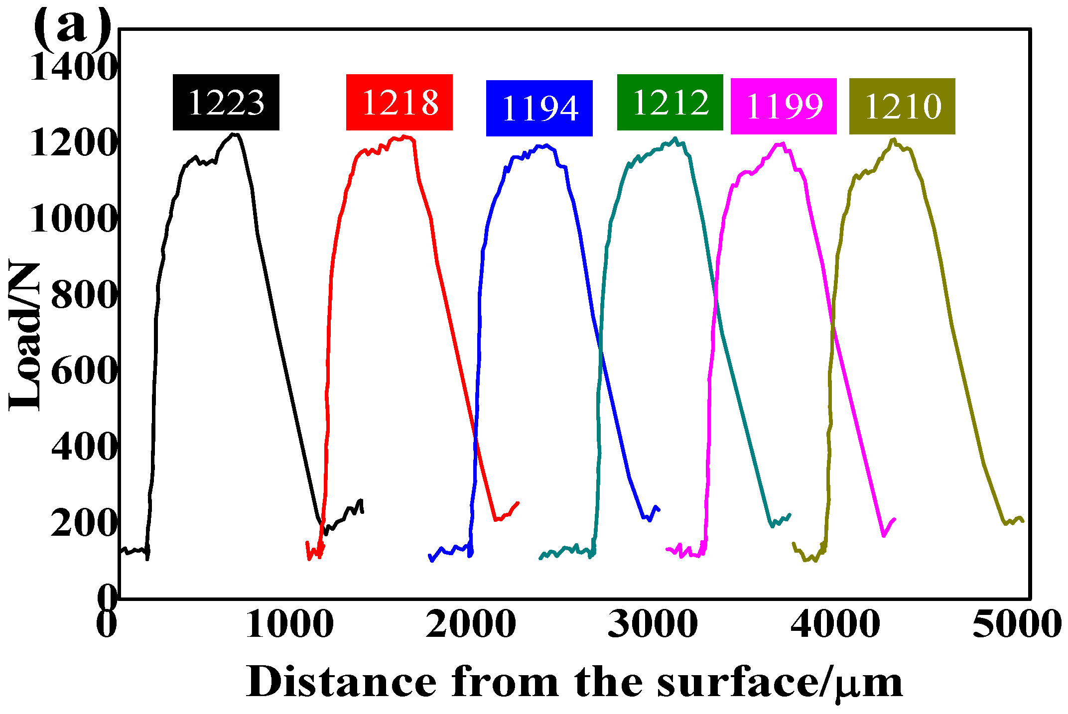
The microshear strength can be used to characterize the connective strength between a cladding zone and substrate material. In this study, shear strength τb was obtained according to the ratio of the maximum load Fmax to the initial cross-sectional area A0 of the sample. Although the peak load on the load–displacement curve reflects the shear resistance of the sample to a certain extent, due to the difference in the cross-sectional size of each specimen after machining and fine grinding, the introduction of shear strength could more accurately characterize the shear resistance ability of each micro area of the cladding layer [34].
Figure 13 shows the shear force-displacement curve of the cladding layer and the repaired sample for multiple tests. The shear force of the matrix was 1200–1300 N, the shear force of the cladding layer was 1400–1500 N, and the shear force of the cladding layer was nearly 200 N higher than that of the matrix. However, the cladding layer and the matrix both had obvious yield phenomena before fracture, showing a good plastic deformation trend. The greater the shear force, the greater the bonding force became, but the brittle tendency also increased accordingly [35]. It can be seen that when the shear force in the bonding zone was less than the maximum shear force, the bonding zone had obvious elastic deformation and uniform plastic deformation stages. When the the maximum shear force was exceeded, the bonding zone exhibited some instantaneous fractures. From the shear force-displacement curve, it can be seen that the shear deformation of the cladding layer was similar to that of the bonding zone. However, the cladding layer had a more obvious yield phenomenon before and after reaching the maximum shear force, and the yield platform was longer, indicating that the cladding layer hinders the formation and propagation of cracks for a longer time and has better plastic deformation than the bonding zone.
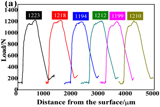
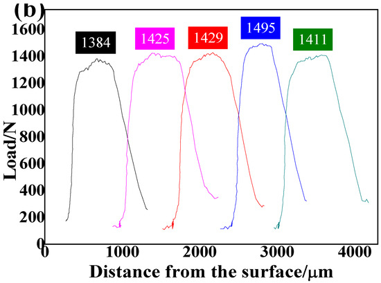
Figure 13.
Shear stress-displacement curve (a) substrate; (b) cladding layer.
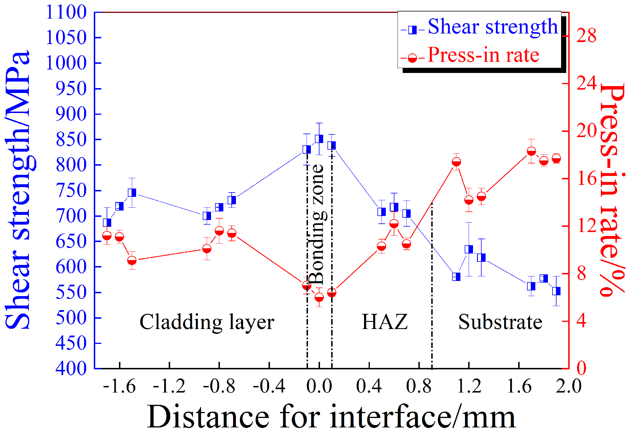
Figure 14 shows the relation curve of the shear strength and the indentation rate of the cladding layer of the FeCrNiMoRE alloy powder remanufacturing sample. It can be seen from the curve that the cladding layer and the substrate of the average indentation rate were basically equal. The average indentation rate of the bonding zone was relatively low, at 7%. The plastic deformation capacity of the substrate was the highest, and the plastic deformation capacity of the cladding zone was similar to that of the heat-affected zone, but the plastic deformation capacity of the bonding zone was relatively low.
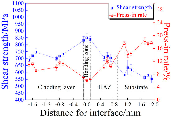
Figure 14.
Gradient curve for the properties of the cladding cross-section.
Compared with Fe314 powder remanufactured sample, the shear strength of each re-gion was basically the same, but the indentation rate was relatively high [10]. This was because the addition of rare-earth elements reduces the amount of carbon and oxygen precipitation in the cladding layer [36,37], preventing them from precipitating into free atoms into the internal stress area or crystal defects and reducing the number of interspace atoms in the intercalation dislocation. Therefore, the plasticity and toughness of the cladding zone were improved, as were the shear strength and plastic deformation capacity of each zone of the cladding layer.
3.4. Fatigue Properties and Strengthening Mechanism
Figure 15 shows the rotating bending fatigue curves of different samples. The fatigue strength of the FeCrNiMoRE powder laser cladding samples was slightly improved compared to that of the matrix at a stress level of 400~450 MPa. When the stress level was higher than 450 MPa, the fatigue strength of the FeCrNiMoRE cladding sample was lower than that of the matrix. The S-N curve was fitted with Basquin Equations (2) and (3) for the matrix and FeCrNiMoRE, respectively. The corresponding fitting correlation coefficients were r1 = 0.786 and r2 = 0.579. It was found that the fitting dispersion degree of FeCrNiMoRE was relatively larger than those of the others [38]. This was because the addition of composite rare-earth elements to the FeCrNiMoRE alloy powder had the effect of refining the grains and the deoxidation and desulfurization of the cladding layer; therefore, inclusion in the cladding layer was reduced, the bonding strength of the interface between the cladding layer and the matrix was increased, and the fatigue resistance was improved.
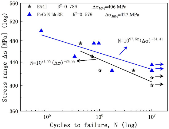
Figure 15.
S-N curve of different samples.
The fracture morphology of the substrate sample is presented in Figure 16. The crack origin is indicated by the circle in Figure 16a, which shows that the main cracks of the sample originated from the surface. Since the loaded stress was parallel to the axial direction, the fatigue crack propagated in the direction perpendicular to the axis to form a flat fracture perpendicular to the axial direction. Figure 16b shows the surface micromorphology of crack initiation. When there were some local weak areas on the surface, cyclic slip occurred, and a cyclic slip band formed under the action of the stress cycle. If the width of the slip band increased to a certain extent, then the dislocation plug and delivery intensified, and a microcrack formed [38].
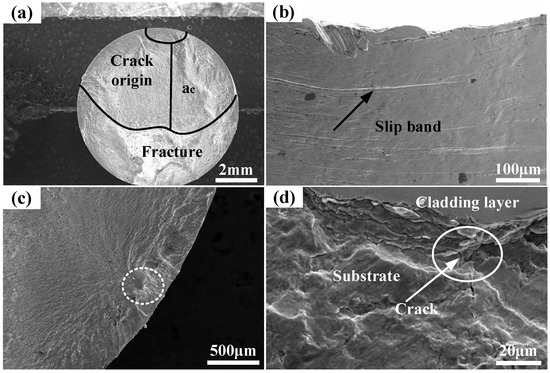
Figure 16.
Fracture morphology of different cladding layers. (a,b) Base material; (c,d) FeCrNiMoRE cladding layer.
The fatigue fracture morphology of the FeCrNiMoRE alloy powder remanufactured sample under the conditions of a stress of 450 MPa and N = 3.36 × 10⁵ is given in Figure 16c. The cracks originated in the heat-affected zone of the substrate below the cladding layer and then expanded along the substrate. Fatigue bands and some small shallow dimples can be observed in the expansion region due to the plastic deformation of surface grains and the formation of slip bands. The fatigue crack propagation direction was perpendicular to the stress axis, forming a flat fracture area. As revealed in the high-magnification images of the microstructure of the expansion region (Figure 16d), the fatigue line grew perpendicular to the crack propagation direction. It was concluded that the fatigue cracks of FeCrNiMoRE samples originated in the heat-affected zone of the substrates. This may have been because the rare-earth elements reacted with oxygen and sulfur during the laser cladding process to deoxidize and desulfurize the cladding layer. Molten purification improved the fatigue performance of the cladding layer.
4. Conclusions
FeCrNiMoRE powder was used for the laser cladding of EA4T steel. The following conclusions were drawn from the experimental results:
- The microstructure of the cladding layer was mainly martensite. With the increase in the distance from the interface, the grains in the cladding layer were gradually re-fined, equiaxed crystals formed at the top of the cladding layer, and a small amount of segregation occurred at the grain boundary. The rare-earth elements in FeCrNi-MoRE alloy powder participated in the metallurgical reaction and combined with O and S to purify the melt. The rare-earth compounds that were generated promoted heterogeneous nucleation and hindered the growth of grains, refining the grains of the cladding layer.
- The microhardness of the cladding layer was the highest, i.e., between 450 and 480Hv0.2, and the distribution of the microhardness was relatively uniform. In the heat-affected zone, the microhardness was between 350 and 400Hv0.2. Compared with that of the cladding layer and the heat-affected zone, the microhardness of the substrate was the lowest.
- In the microshear test, an obvious yield phenomenon occurred before the shear fracture of each microregion of the repaired sample, and it had good plastic deformation ability. Compared with those of the matrix and cladding layer, the interface had the highest shear performance but the worst plastic deformation ability. The cladding layer had good comprehensive shear performance. Compared with Fe314 powder remanufactured sample, in each region of cladding layer, shear strength and plastic deformation ability increased.
- The fatigue cracks of the remanufactured FeCrNiMoRE alloy powder samples mainly originated in the heat-affected zone of the matrix. The addition of rare-earth elements changed the crack initiation from the surface to the internal mechanism. At the same time, the addition of rare-earth elements refined the grains and improved the fatigue strength of the sample.
Author Contributions
Data curation, Q.C. (Qunyan Chen) and Q.C. (Qing Cai); Formal analysis, W.C.; Methodology, Z.Z.; Software, S.T. All authors have read and agreed to the published version of the manuscript.
Funding
The authors are grateful for the support by Sichuan Province Science and Technology Support Program (CN) [No.2020YFH0134] [2021YFG0095] and Key Project of Xihua University (No. Z202123).
Institutional Review Board Statement
Not applicable.
Informed Consent Statement
Not applicable.
Data Availability Statement
Not applicable.
Conflicts of Interest
The authors declare no conflict of interest.
References
- Smith, R.A.; Hillmansen, S. A brief historical overview of the fatigue of railway axles. roc. Inst. Mech. Eng. Part F J. Rail Rapid Transit 2005, 218, 267–277. [Google Scholar] [CrossRef]
- Chen, W.; Chen, H.; Li, C.; Wang, X.; Cai, Q. Microstructure and fatigue crack growth of EA4T steel in laser cladding remanufacturing. Eng. Fail. Anal. 2017, 79, 120–129. [Google Scholar] [CrossRef]
- Cheng, L.; Yu, J.J. Fracture analysis of railway freight train tangent shaft. Phys. Chem. Insp.-Phys. 2006, 42, 149–151. [Google Scholar]
- Xu, B.S.; Wang, H.D.; Ma, G.Z. Advanced surface engineering technologies for remanufacturing forming. Rare Met. Mater. Eng. 2012, 41, 1–5. [Google Scholar]
- Rudavskyi, D.; Kaniuk, Y.; Duriagina, Z.; Kulyk, V.; Shefer, M.; Dolinska, I. Assessing surface fatigue crack growth in railway wheelset axle. Arch. Mater. Sci. Eng. 2020, 106, 59–67. [Google Scholar] [CrossRef]
- Feng, X.; Cui, X.; Zheng, W.; Wen, X.; Zhao, Y.; Jin, G.; Lu, B.; Dong, M. Performance of underwater laser cladded nickel aluminum bronze by applying zinc protective layer and titanium additives. J. Mater. Process. Technol. 2019, 266, 544–550. [Google Scholar] [CrossRef]
- Duan, X.; Gao, S.; Dong, Q.; Zhou, Y.; Xi, M.; Xian, X.; Wang, B. Reinforcement mechanism and wear resistance of Al2O3/Fe-Cr-Mo steel composite coating produced by laser cladding. Surf. Coat. Technol. 2016, 291, 230–238. [Google Scholar] [CrossRef]
- Xie, Y.J.; Huang, B.S.; Zhuang, J.; Chen, W.; Hu, J. Microstructure and Corrosion Resistance of Fe314 Alloy Prepared by Laser Cladding on EA4T Steel Surface. Int. J. Electrochem. 2020, 15, 11584–11593. [Google Scholar] [CrossRef]
- Liu, H.; Wang, C.; Zhang, X.; Jiang, Y.; Cai, C.; Tang, S. Improving the corrosion resistance and mechanical property of 45 steel surface by laser cladding with Ni60CuMoW alloy powder. Surf. Coat. Technol. 2013, 228, 296–300. [Google Scholar] [CrossRef]
- Chen, W.J.; Chen, Q.Y.; Mao, Y.; Tang, S.C. Effect of laser cladding on microstructuraltransformation and mechanical properties of heat affected zone of EA4T steel. Mater. Express 2021, 11, 1707–1715. [Google Scholar] [CrossRef]
- Xie, Y.; Chen, W.; Liang, L.; Huang, B.; Zhuang, J. Influence of laser power on the microstructure and properties of Fe314 alloy cladding layer on EA4T steel. Weld. World 2022, 66, 1551–1563. [Google Scholar] [CrossRef]
- Da Sun, S.; Liu, Q.; Brandt, M.; Luzin, V.; Cottam, R.; Janardhana, M.; Clark, G. Effect of laser clad repair on the fatigue behaviour of ultra-high strength AISI 4340 steel. Mater. Sci. Eng. A 2014, 606, 46–57. [Google Scholar] [CrossRef]
- Li, Z.D.; Guo, G.X. The influence of laser cladding on the fatigue life of 30CrMnSiA steel specimens. J. Mech. Strength 1998, 20, 67–69. [Google Scholar]
- Zhang, P.F.; Wang, J. Study on Microstructure and Fracture Mechanism of Motor Shaft by Laser Repair. Master’s Thesis, Shandong University, Jinan, China, 2015; pp. 1–10. [Google Scholar]
- Garrison, W.M.; Maloney, J.L. Lanthanum additions and the toughness of ultra-high strength steels and the determination of appropriate lanthanum additions. Mater. Sci. Eng. A 2005, 403, 299–310. [Google Scholar] [CrossRef]
- Wang, K.; Zhang, Q.; Sun, M.; Wei, X.; Zhu, Y. Rare earth elements modification of laser-clad nickel-based alloy coatings. Appl. Surf. Sci. 2001, 174, 191–200. [Google Scholar] [CrossRef]
- EN13260:2009+A1:2010; Railway Applications-Wheelsets and Bogies-Wheelsets-Product Requirements. European Committee for Standardization: Brussels, Belgium, 2010; pp. 30–31.
- GB/T228.1-2010; Metallic Material-Tensile Testing-Method of Test at Ambient Temperature. Standards Press of China: Beijing, China, 2010; pp. 1–19.
- GB/T 229-2007; Metallic Materials-Charpy Pendulum Impact Test Method. Standards Press of China: Beijing, China, 2007; pp. 1–13.
- Duriagina, Z.A.; Lemishka, I.A.; Trostianchyn, A.M.; Kulyk, V.V.; Shvachko, S.G.; Tepla, T.L.; Pleshakov, E.I.; Kovbasyuk, T.M. The Effect of Morphology and Particle-Size Distribution of VT20 Titanium Alloy Powders on the Mechanical Properties of Deposited Coatings. Sov. Powder Met. Met. Ceram. 2019, 57, 667–702. [Google Scholar] [CrossRef]
- ASTM E384-11e1; Method for Nooule and Vickers Hardness of Materials. American Society for Materials and Experimentation: West Conshohocken, PA, USA, 2011; pp. 1–43.
- Lei, B.L.; Wang, Y.L. Microshear test method and its application in welding technology. J. Southwest Jiaotong Univ. 1990, 1, 14–20. [Google Scholar]
- GB/T4337-2015; Metallic- Fatigue Test-Rotating Bar Bending Method. National standard of the People’s Republic of China, China Standards Press: Beijing, China, 2015; pp. 1–9.
- Chen, W.J.; Chen, H.; Wang, Y.J. Characteristics of Ni-Cr-Fe laser clad layers on EA4T steel. Int. J. Mod. Phys. B 2017, 31, 6–11. [Google Scholar] [CrossRef]
- Sindo, K. Welding Metallurgy, 2nd ed.; Yan, J.C., Yang, J.G., Zhang, G.J., Eds.; Higher Education Press: Beijing, China, 2012; pp. 145–153. [Google Scholar]
- Ding, L.; Hu, S.; Quan, X.; Shen, J. Effect of Mo and nano-NdO on the microstructure and wear resistance of laser cladding Ni-based alloy coatings. Appl. Phys. A Mater. Sci. Process. 2016, 122, 288. [Google Scholar] [CrossRef]
- Cui, Z.Q.; Qin, Y.C. Metal Science and Heat Treatment, 2nd ed.; Machinery Industry Press: Beijing, China, 2011; pp. 300–320. [Google Scholar]
- Xiang, S.; Mao, S.; Shen, Z.; Long, H.; Wei, H.; Ma, S.; Zhang, J.X.; Chen, Y.H.; Zhang, J.F.; Liu, Y.N. Site preference of metallic elements in M23C6 carbide in a Ni-based single crystal superalloy. Mater. Des. 2017, 129, 9–14. [Google Scholar] [CrossRef]
- Yan, M.G.; Chen, X.Y. Strengthening of nickel base superalloy. Acta Metall. Sin. 1964, 7, 307–321. [Google Scholar]
- Zhang, F.Y.; Chen, H.; Xu, Y.K.; Zhang, X.M. Influence of Mo Content on Microstructure and Microhardness of Laser Solid Formed Ti-6Al-Mo System Alloys. Rare Met. Mater. Eng. 2013, 42, 1332–1336. [Google Scholar]
- Tewari, R.; Mazumder, S.; Batra, I.; Dey, G.; Banerjee, S. Precipitation in 18 wt% Ni maraging steel of grade 350. Acta Mater. 2000, 48, 1187. [Google Scholar] [CrossRef]
- Li, F.; Li, W.C. Metallurgy and Thermodynamics of Materials; Metallurgical Industry Press: Beijing, China, 2012; pp. 480–483. [Google Scholar]
- Lu, J.W. Thermodynamics Calculation and Structure Properties Resrarch of Heat-Resistant Steel GX12. Master’s Thesis, Harbin University of Science and Technology, Harbin, China, 2009; pp. 21–31. [Google Scholar]
- Hao, Z.M. Materials Thermodynamics; Chemical Industrial Press: Beijing, China, 2004; pp. 182–190. [Google Scholar]
- Zhu, L.; Ren, G.S.; Long, L.; Che, H.Y. Determination of local constitutive properties of aluminum alloy welded joints by double hole micro shear. Mater. Eng. 2007, 10, 18–22. [Google Scholar]
- Zhao, P.; Wang, X.; Yan, E.; Misra, R.; Du, C.; Du, F. The influence of inclusion factors on ultra-high cyclic deformation of a dual phase steel. Mater. Sci. Eng. A 2019, 754, 275–281. [Google Scholar] [CrossRef]
- Zhu, Z.K. Application of Rare Earth in Iron and Steel; China Machine Press: Beijing, China, 1987; p. 239. [Google Scholar]
- Zheng, X.L.; Wang, H.; Yan, J.H. Material Fatigue Theory and Engineering Applications; Science Press: Beijing, China, 2013; p. 165. [Google Scholar]


Publisher’s Note: MDPI stays neutral with regard to jurisdictional claims in published maps and institutional affiliations. |
© 2022 by the authors. Licensee MDPI, Basel, Switzerland. This article is an open access article distributed under the terms and conditions of the Creative Commons Attribution (CC BY) license (https://creativecommons.org/licenses/by/4.0/).