Abstract
Fiber carbon (FC) is a potential fast-chargeable anode, which is attributable to the many nanopores in the cell wall. Herein, a strategy for an FC@MnO@rGO composite is proposed to combine pine-based FCs with suitable MnO nanoparticles, which are enfolded by the reduced graphene oxide (rGO). The magic conception is performed to join the advantages of conductive FC skeleton, high theoretical capacity of MnO and high flexibility and conductivity of rGO. Compared to FC, FC@MnO@rGO composite materials have presented superior lithium storage properties, exhibiting an initial discharge capacity of 1191.8 mAh g−1 and charge capacity of 643.5 mAh g−1. It is worth attention that the FC@MnO@rGO shows a reversible capacity of 304.2 mAh g−1 at a current density of 2 A g−1. Furthermore, it delivers an improved capacity retention of 67% at 400 mA g−1 over 400 cycles.
1. Introduction
The advent of carbon neutrality drives the boom in lithium-ion batteries (LIBs) [1,2]. LIBs with graphite as anodes are popularly supplied within the fields of electronics and power vehicles. However, the disadvantage of low theoretical capacity in graphite (372 mAh g−1) hinders its application in the field of energy storage [3,4,5]. Compared with commercial graphite, biomass-derived carbons and composite anodes can display improved electrochemical performance. Biomass-derived carbons have been viewed as the booming anode material for LIBs on account of their desirable intrinsic porous structures and three-dimensional architectures, which are beneficial to Li+ storage [6,7,8,9]. Fibers extracted from plant-based materials are carbonized as sustainable anodes in LIBs, which have presented a relatively larger specific area and considerably concentrated-range pore diameter [10]. It is expected to deliver good cycling stability, which can exhibit a large reversible capacity around 389–434.9 mAh g−1 at a current density of 50 mA g−1.
The low-cost MnO is a popular anode material for LIBs, which possesses low conversion potential and voltage hysteresis (<0.8 V), high density (5.43 g cm−3) and theoretical capacity (756 mAh g−1) [11,12]. Nevertheless, the drastic volume change and pathetic electron conductivity of MnO have resulted in poor electrochemical performance [13]. Up to now, some efforts have been made to solve the issues, as follows: coating or integrating MnO with carbon materials [14,15], reducing particle size to nanoscale [12,16]. MnO compounding one type of carbon is limited in improving battery performance. How to better combine biomass-derived carbon with MnO is the challenge.
Herein, it is proposed to conceive pine-fiber-derived carbons (FCs) with suitable MnO nanoparticles, which could be enfolded by the reduced graphene oxide (rGO), namely FC@MnO@rGO (Figure S1). The special structure based on the conductive carbon-fiber skeleton could, consequently, dominate the high theoretical capacity in MnO and high flexibility in rGO. The ternary composite structure containing two kinds of carbon can effectively exert more stable performance. Compared to the FC@MnO, FC@MnO@rGO displays greater electrochemical performance. The plant fibers could be carbonized and functionalized, then it would present a beautiful spring in the potential application of new energy.
2. Materials and Methods
2.1. Synthesis of FC@MnO@rGO
The pine wood was smashed into powders, then treated with HNO3 (30 wt%, Sinopharm) at 80 °C for 4 h. The sample was then carbonized at 1000 °C for 1 h under argon flow (200 mL min−1) and, finally, carbon fibers were obtained. FC (1 g) and KMnO4 (1 g) were mixed and stirred in 50 mL deionized water for 30 min, then transferred into Teflon autoclave, keeping at 160 °C for 6 h. After cooling down, the solid product was filtered and washed with deionized water three times and then heated at 500 °C for 2 h to obtain FC@MnO. Additionally, FC (1 g) and KMnO4 (1 g) were mixed and stirred in 50 mL deionized water for 30 min, then transferred into Teflon autoclave, reacting at 160 °C for 6 h. After cooling down, the semi-finished products (1 g) and different amounts of GO (X g) were mixed in 50 mL deionized water under stirring for 30 min, followed by hydrothermal reaction (120 °C, 12 h). Successively, the obtained precursor was heated at 500 °C for 2 h, namely FC@MnO@rGO. Herein, the samples of FC@MnO@rGO, FC@MnO@rGO-1 and FC@MnO@rGO-2 were also prepared, according to different amounts of GO with X = 0.05, 0.1 and 0.2, respectively.
2.2. Characterizations
The X-ray powder diffraction (XRD) patterns were conducted with X’Pert PRO MPD under Cu Kα radiation (λ = 1.5418 Å). Raman spectra were performed by Thermo Fischer DXR Raman spectrometer under ambient temperature (laser wavelength: 532 nm, power: 100 mw). Thermal gravimetric (TG) measurements were detected by STA 409C thermogravimetry from 30 °C to 790 °C, 10 °C·min−1 under air atmosphere. The pore structure and Brunauer–Emmett–Teller (BET) surface area was characterized with N2 adsorption–desorption isotherms instrument. X-ray photoelectron spectroscopy (XPS) was collected on Thermo Fisher Scientific ESCALAB 250Xi equipment with Al Kα radiation (energy: 1486.6 eV). The surface morphology and microstructures of the materials were observed by field emission scanning electron microscopy (FESEM, S-4800, Hitachi, Tokyo, Japan) and transmission electron microscope (TEM, 2100F, JEOL, Tokyo, Japan).
2.3. Electrochemical Test
CR2016 coin cells were assembled to test the electrochemical performance of the samples, using Li metal as the counter electrode. The electrolyte was 1 M LiPF6 in diethyl carbonate, ethylene carbonate and dimethyl carbonate (volume ratio of 1:1:1). The working electrode was mixed with active materials, conductivity material (super P) and binder (PVDF) under a weight ratio of 8:1:1. All the mixture was dissolved in N-methyl pyrrolidinone. Then it was coated evenly on copper foil and dried in a vacuum oven at 90 °C for 6 h. After standing for 12 h, the charge and discharge performances were investigated using LAND battery testing system with a range of 0.001–3 V (vs. Li/Li+) at various current densities ranging from 50 mA g−1 to 2000 mA g−1. Cyclic voltammograms (CV) were performed at the Ivium electrochemical station with voltage scan rate of 0.1 mV s−1. Electrochemical impedance spectroscopy (EIS) was obtained using the same equipment, the frequency ranges from 0.01 to 100 kHz with a voltage of 5 mV amplitude.
3. Results
3.1. Structure Parameters of FC, FC@MnO and FC@MnO@rGO
The XRD was displayed to investigate the composition and structure of the FC, FC@MnO and FC@MnO@rGO, as shown in Figure 1a. The typical pattern of MnO (JCPDS card No. 06-0592) is found in FC@MnO and FC@MnO@rGO, with characteristic peaks at 2θ ≈ 35°, 40°, 59°, 70° and 73°, corresponding to (111), (200), (220), (311) and (222) planes [17]. The obvious diffraction peaks at 2θ ≈ 24°, 44° belonged to (002) and (100) planes were observed in FC, indicating the structure of amorphous carbon. Compared to the FC sample, the peaks of (002) and (100) planes are faint for FC@MnO and FC@MnO@rGO, which is attributed to the relatively low intensity of amorphous carbon. The XRD curves for FC@MnO@rGO-1 and FC@MnO@rGO-2 (shown in Figure S2a) are similar to that of FC@MnO@rGO, indicating the amount of rGO has negligible effects on the crystal structure and crystallinity in the composite material.
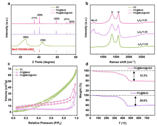
Figure 1.
(a) XRD curves, (b) Raman patterns and (c) N2 adsorption isotherms of FC, FC@MnO and FC@MnO@rGO. (d) TG splines of FC@MnO and FC@MnO@rGO.
Raman spectra are conducted to detect the structure change. Raman spectra (Figure 1b) show two high-intensity and broad peaks at ~1330 cm−1 (D band) and ~1580 cm−1 (G band) for FC, FC@MnO and FC@MnO@rGO. The D band is caused by the disordered structure of graphene. The G band arises from the stretching of the C-C bond in graphitic materials and is common to all sp2 carbon systems [18,19]. Generally, the intensity ratio of the D band to the G band (ID/IG) represents the degree of graphitization [20]. The ID/IG value of FC, FC@MnO and FC@MnO@rGO is about 1.04, 1.03 and 1.01, respectively, demonstrating that the mixing of MnO and rGO negligibly changes the graphitic structure in FC. Furthermore, a weak plane at ~640 cm−1 is corresponding to the Mn-O peaks of FC@MnO and FC@MnO@rGO. It is confirmed that manganese oxide still exists in the composites materials [20]. The Raman spectra of FC@MnO@rGO, FC@MnO@rGO-1 and FC@MnO@rGO-2 are shown in Figure S2b; the ID/IG is calculated to be about 1.01, 0.99 and 0.99, indicating the degree of graphitization experiences negligible variations with changing the amount of rGO.
The porous texture of FC, FC@MnO and FC@MnO@rGO was researched by nitrogen adsorption/desorption isotherm at 77 K, which is shown in Figure 1c. The contour of the isotherm indicates the prominent feature of the II-type isotherm [21], revealing the significant macropores provided by FC instead of micropores. The BET was 13.9, 15.5 and 31.3 m2 g−1 for FC, FC@MnO and FC@MnO@rGO, respectively. This shows that the large specific surface area of MnO nanoparticles and rGO contributes to the improvement in SBET. The large specific surface area of FC@MnO@rGO is beneficial to the electrolyte infiltration into composite materials, facilitating lithium ion transport. The specific surface area of FC@MnO@rGO, FC@MnO@rGO-1 and FC@MnO@rGO-2 is 31.3, 43.8 and 66.5 m2 g−1, respectively (Figure S2c). The amount of graphene is positively correlated with the specific surface area, indicating that different amounts of graphene are successfully coated on the composite material.
The MnO content was estimated by TG curves with the decomposition behavior at air atmosphere from 30 to 790 °C of FC@MnO and FC@MnO@rGO, as shown in Figure 1d. The two curves demonstrate rapid weight loss beginning at ~300 °C and the weight becomes stable at ~500 °C. The MnO content in FC@MnO and FC@MnO@rGO is evaluated to be ~50.9 wt % and 71.6 wt%.
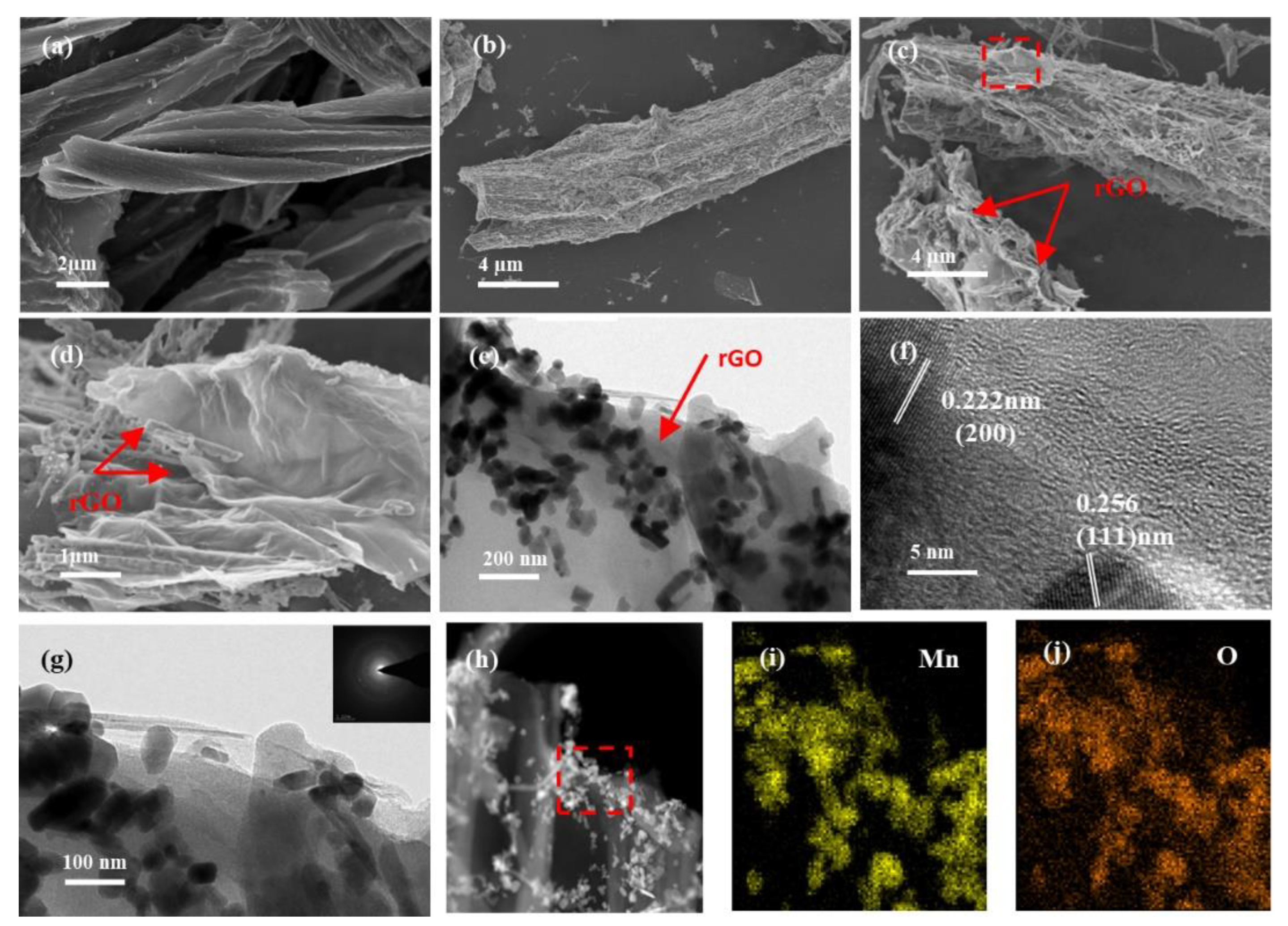
The SEM images compare the morphology and surface microstructure in the FC, FC@MnO and FC@MnO@rGO (Figure 2a–d). It displays that the carbon fibers are observed and the diameter of a single fiber is no more than 8 µm (Figure 2a). The MnO nanowires are observed in FC@MnO and FC@MnO@rGO (Figure 2b,c). Typical thin and wrinkled sheets of rGO are observed at the edge of the FC (red arrows in Figure 2c,d), which is also confirmed by the TEM results.

Figure 2.
(a) SEM of FC, (b) SEM of FC@MnO, (c,d) SEM of FC@MnO@rGO, (e) TEM of FC@MnO@rGO, (f) HRTEM of FC@MnO@rGO, (g) TEM and SAED (inset in (g)), (h) STEM and corresponding elemental mapping of (i) Mn and (j) O for FC@MnO@rGO.
The TEM images (Figure 2e–j) demonstrate the morphology and microstructure of FC@MnO@rGO. It can be observed that a large number of MnO nanowires and nanoparticles encapsulated by a thin graphene layer are produced at the end of the FC (Figure 2e), while only MnO nanowires are distributed in FC@MnO (see Figure S3a). The difference is supposed to be caused by the large amount of oxygen functional groups in the graphene oxide layer. Figure 2f displays the HRTEM images of FC@MnO@rGO, where the lattice spacing is calculated to be 0.222 nm and 0.256 nm, assigning to the (200) and (111) planes of the MnO phase [22]. Moreover, the graphene consisting of several stacked layers can be observed in terminals of FC, revealing that graphene oxide is reduced under high heating temperature. Figure S3b shows the amorphous structure of FC and the (200) plane of the MnO, which is in agreement with the results of the XRD. As confirmed by the selected area electron diffraction (SAED), the FC@MnO@rGO consists of polycrystalline compounds (inset of Figure 2g). Figure 2h–j and Figure S4 illustrate that C, O and Mn elements all distribute uniformly in the carbon fibers, with a considerable amount; the O dispersion agrees well with the Mn, indicating the Mn and O elements are well involved in the MnO oxides. This unique structure of FC@MnO@rGO material as an anode material possesses several merits: a. the hollow structure fully absorbs the electrolyte and shortens the diffusion path of lithium ions; b. the composite structure and graphene layer can absorb the volume expansion of MnO during the charge/discharge process, enhancing the cycling stability; and c. the three-dimensional conducting framework constructed by FC and the graphene layer can promote the rapid transport of electrons.
3.2. Elementary Analysis of FC@MnO and FC@MnO@rGO
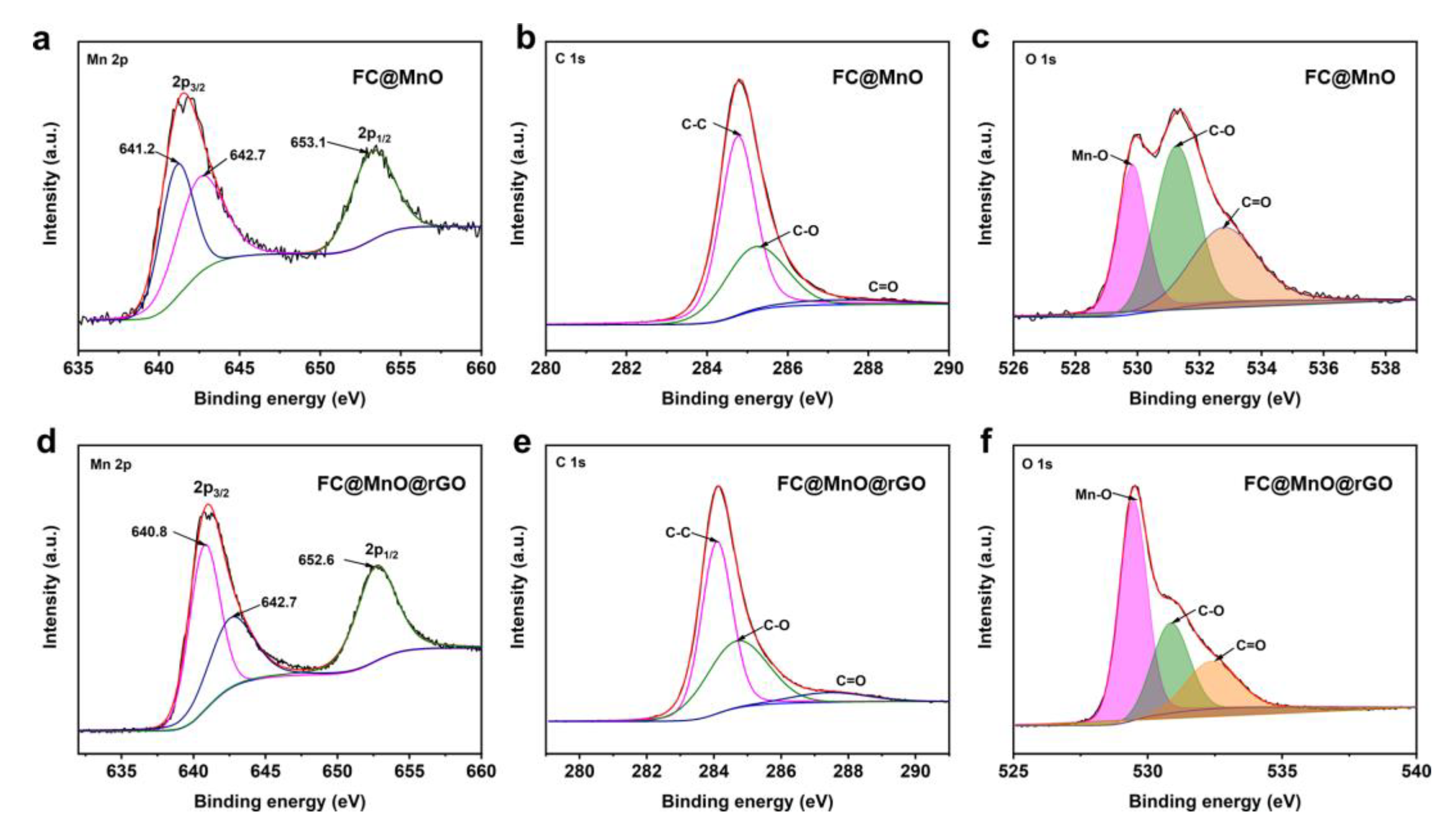
The elemental compositions of FC@MnO and FC@MnO@rGO were analyzed by XPS testing. The predominant peaks at ~284.2 eV, ~531.6 eV and ~641.0 eV arise from C 1s, O 1s and Mn 2p (Figure S2d), respectively [14]. The proportions of C, O and Mn elements in FC@MnO@rGO were 69.20, 23.51 and 7.29 at%, respectively, while the C, O and Mn elements were 79.34, 17.33 and 3.33 at% in FC@MnO, as shown in Table S1, suggesting that the proportions of O and Mn elements were improved by the enveloped rGO. The Mn 2p spectra show two main peaks at ~641 eV and ~653 eV, assigned to Mn 2p3/2 and Mn 2p1/2 (Figure 3a,d). The spin-orbit splitting of Mn 2p is separated into a double state of 12.3 eV, indicating that Mn (II) is the main ingredient in the composite materials [23]. The shift in Mn 2p bonding energy indicates the strong interaction between carbon materials and MnO [11,24]. The C 1s spectra shown in Figure 3b,e are well fitted with three peaks at ~288.9 eV, ~285.9 eV and ~284.7 eV, which are assigned to C=O, C-O and C-C bonding, respectively. The deconvolution of O1s spectra displayed in Figure 3c,f reveals that O 1s is fitted to Mn-O, C-O and C=O bonding, respectively, also indicating the presence of MnO. Meanwhile, the intensity of Mn-O increases with the addition of rGO wrapped. These results show that rGO is successfully coated on FC@MnO, which is consistent with the results of SEM and TEM (Figure 2). The XPS surveys of FC@MnO@rGO, FC@MnO@rGO-1 and FC@MnO@rGO-2 are shown in Figure S2d, indicating that the three composite materials have analogous elemental composition and surface chemistry.
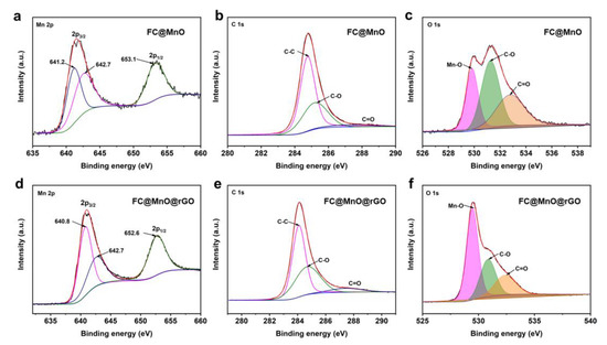
Figure 3.
High-resolution spectra of the (a–c) Mn 2p, C 1s and O 1s peaks of FC@MnO, (d–f) Mn 2p, C 1s and O 1s peaks of FC@MnO@rGO, respectively.
3.3. Electrochemical Performance of FC, FC@MnO and FC@MnO@rGO
The electrochemical performances of FC, FC@MnO and FC@MnO@rGO electrodes are further investigated. The cyclic voltammograms (CVs) of FC, FC@MnO and FC@MnO@rGO between 0 V and 3.0 V (vs Li/Li+) are shown Figure S5a. The CV profiles of FC@MnO and FC@MnO@rGO are similar, but fairly different from FC in the first cycle. Specifically, the discharge curve exhibits a weak reduction peak at ~0.5 V for FC@MnO and FC@MnO@rGO, resulting from the formation of the solid electrolyte interphase (SEI) layer during the initial lithium intercalation process. The discharge curve shows an intense cathodic peak ~0.2 V, which is due to the initial reduction of MnO to Mn, the formation of amorphous Li2O (MnO + 2Li+ + 2e− → Mn + Li2O) [14,25]. For the second circle in the CV curves, as shown in Figure S5b, the intense peak shifts to about 0.4 V, which is caused by the improved kinetics in the FC@MnO and FC@MnO@rGO. In the first and second cycle, the anodic peaks of ~1.3 V in the charge branches are ascribed to the decomposition of Li2O (Mn + Li2O → MnO + 2Li++ 2e−) [26].
Figure 4a compares the galvanostatic charge–discharge (GCD) curves at a current density of 50 mA g−1 of FC, FC@MnO and FC@MnO@rGO electrodes. The initial discharge capacities of the three electrodes are 557.8, 923.3 and 1191.8 mAh g−1, and the charge capacities are 366.6, 514.2 and 643.5 mAh g−1. The capacity decrease in FC@MnO and FC@MnO@rGO is mainly caused by the interfacial reaction between MnO and the electrolyte or SEI layer formation, which is consistent with other transition metal oxide anodes [27,28]. It can be seen that the maximum capacity provided by FC@MnO@rGO is close to the theoretical capacity of MnO (756 mAh g−1) based on all active materials, including FC, MnO and rGO components. It is supposed that the nano-MnO and conductive rGO can promote the capacity, enhance charge transfer and improve the efficiency of the conversion reaction. In addition, the high electronic conductivity of FC and rGO can enhance the reversible MnO conversion rate and facilitate electron transfer. Different from the FC electrode, the FC@MnO and FC@MnO@rGO represent a long steady stage around 0.2 V in the discharge branches. Considering the charge patterns, FC@MnO and FC@MnO@rGO have a short plateau at ~1.3 V, which is highly in agreement with the CV results. The FC@MnO@rGO-1 and FC@MnO@rGO-2 deliver initial discharge capacity of 1102 and 1079 mAh g−1 and charge capacities of 565.3 and 565.5 mAh g−1, respectively (Figure S6a). FC@MnO@rGO is superior to FC@MnO@rGO-1 and FC@MnO@rGO-2. It indicates that the increased proportion of rGO in the composite material leads to lower specific capacity.
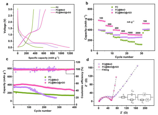
Figure 4.
The electrochemical performance of FC, FC@MnO and FC@MnO@rGO. (a) The initial galvanostatic charge–discharge profiles tested at 50 mA g−1. (b) Rate capability performances at various current densities. (c) Stability performances at 400 mA g−1. (d) EIS results and fitting curves of FC@MnO and FC@MnO@rGO.
Figure 4b shows the rate performance of FC, FC@MnO and FC@MnO@rGO electrodes at stepped specific currents between 100 and 2000 mA g−1. The FC@MnO@rGO exhibits capacity of 586.2, 484.6, 400.2, 334.7, 309.4, 305.1 and 304.2 mAh g−1, which is far superior to the FC and FC@MnO. Further, we list the performance with those reported in other studies in Table S2. It can be seen that FC@MnO@rGO has comparable performance. The rate performance of FC@MnO@rGO-1 and FC@MnO@rGO-2 are also compared in Figure S6b, exhibiting inferior capacities to FC@MnO@rGO. The excellent rate performance of FC@MnO@rGO is associated with the synergic effects of carbon fiber, graphene layers and nano-MnO. Notably, the proportion of rGO is also significant, because increasing rGO results in lower reversible capacity due to its limited capacity contribution.
Long-time cycling was performed under a current density of 400 mA g−1 for FC, FC@MnO and FC@MnO@rGO (Figure 4c). The specific capacity in the FC electrode decreases sharply from 229 to 139.2 mAh g−1 after 400 cycles, FC@MnO decreases from 348.8 to 81.7 mAh g−1 after 280 cycles, while FC@MnO@rGO decreases from 384.3 to 257.3 mAh g−1 after 400 cycles, resulting in capacity retentions of 60.8%, 23.4% and 67.0%, respectively. The FC@MnO exhibits much poorer cycling stability, which is associated with the severe volume change in MnO during the cycling process. The cycling stability of FC@MnO@rGO-1 and FC@MnO@rGO-2 at the same current density (400 mA g−1) is also represented in Figure S6c. It can be seen that the special structure of FC@MnO@rGO can improve cycle performance, which is attributed to the graphene layer relieving the volume expansion of MnO during the cycling cycles. Moreover, the macro and micropores offer spaces for MnO to adapt the volume changes.
In order to verify the performance improvement mechanism in the FC@MnO and FC@MnO@rGO, the electrochemical impedance spectroscopy (EIS) was analyzed (Figure 4d). The Nyquist plots consist of a semicircle, corresponding to the charge transfer resistance (Rct) in the electrode material at high frequency and a straight line corresponding to the Warburg impedance (Zw) of Li+ diffusion at low frequency [29,30]. Generally, Rct has an important influence on the rate performance of the electrode. According to the equivalent circuit-fitted data, the values of the Rct for the FC@MnO and FC@MnO@rGO electrode are 63.97 Ω and 41.6 Ω, respectively. The Nyquist plots of FC@MnO@rGO-1 and FC@MnO@rGO-2 are displayed in Figure S6d and the values of the Rct for these two samples are 56.8 Ω and 45.6 Ω. It is concluded that the low impedance of FC@MnO@rGO is induced by the conductive FC and rGO. Further, they are able to alleviate volume expansion in MnO, thus, facilitating lithium ion and electron transfer through the electrode and electrolyte interface, resulting in superior electrochemical kinetics.
According to the analysis of the electrochemical performance of FC@MnO@rGO as the anode material, the unique structure and the graphene layer are the main reasons for its enhanced cycle performance and rate performance. Firstly, the hollow structure can shorten the migration distance of Li+. Secondly, FC and the reduced graphene oxide sheet constructing three-dimensional conducting framework increase the electronic conductivity in the material. Moreover, the pore structure offers limited spaces for MnO to reduce the volume expansion. Due to these merits, FC@MnO@rGO as an anode material for lithium-ion batteries exhibits satisfactory performance.
4. Conclusions
In summary, the cost-effective FC@MnO@rGO anodes are thoroughly examined, which are made of easily available pine, manganese precursors and graphene oxide. The FC@MnO@rGO is confirmed to present strong electron transport capability, volume expansion limitation and enhanced lithium storage capacity due to the synergistic effect of carbon fiber, MnO and rGO. In consequence, FC@MnO@rGO displays high reversible capacity, excellent rate performance and outstanding cycle stability as an anode of lithium-ion batteries. The initial discharge capacity of FC@MnO@rGO is 1191.8 mAh g−1 and charge capacity is 643.5 mAh g−1. Further, FC@MnO@rGO delivers a reversible capacity of 304.2 mAh g−1 at a current density of 2 A g−1. The cycling stability with a capacity retention was modified to 67% after 400 cycles. It is significantly different to exploit a synthesis of FC@MnO@rGO electrodes with high electrochemical performance.
Supplementary Materials
The following supporting information can be downloaded at: https://www.mdpi.com/article/10.3390/coatings12081139/s1, Figure S1: Schematic illustration of the preparation of the FC@MnO@rGO; Figure S2: Characterization of FC@MnO@rGO, FC@MnO@rGO-1 and FC@MnO@rGO-2; Figure S3: TEM images, STEM and corresponding elemental mapping of C, O and Mn for FC@MnO; Figure S4: The corresponding elemental mapping of C for FC@MnO@rGO; Figure S5: CV curves of FC, FC@MnO and FC@MnO@rGO; Figure S6: Electrochemical performance of FC@MnO@rGO, FC@MnO@rGO-1 and FC@MnO@rGO-2; Table S1: The proportions of FC@MnO and FC@MnO@rGO; Table S2: Summary for the results for advanced anodes for LIBs. References [15,31,32,33,34,35] are cited in the supplementary materials.
Author Contributions
Conceptualization, Q.H., B.F. and X.Z.; writing—original draft, J.H. and S.C.; writing—reviewing and editing, W.D.; data curation, G.L.; validation, G.S.; investigation, J.H. and Y.L.; resources, J.H. and G.X.; supervision. All authors have read and agreed to the published version of the manuscript.
Funding
This research was supported by the Hunan Provincial Natural Science Foundation of China (2020JJ2058), Hunan Provincial Forestry Technological Innovation Funds (XLK202107-3) and Scientific Research Foundation of Hunan Provincial Education Department (18A159).
Institutional Review Board Statement
Not applicable.
Informed Consent Statement
Not applicable.
Data Availability Statement
The data presented in this study are available on request from the corresponding author.
Conflicts of Interest
The authors declare no conflict of interest.
References
- Duffner, F.; Kronemeyer, N.; Tübke, J.; Leker, J.; Winter, M.; Schmuch, R. Post-lithium-ion battery cell production and its compatibility with lithium-ion cell production infrastructure. Nat. Energy 2021, 6, 123–134. [Google Scholar] [CrossRef]
- Masias, A.; Marcicki, J.; Paxton, W.A. Opportunities and Challenges of Lithium Ion Batteries in Automotive Applications. ACS Energy Lett. 2021, 6, 621–630. [Google Scholar] [CrossRef]
- Cao, Y.; Xiao, L.; Ai, X.; Yang, H. Surface-modified graphite as an improved intercalating anode for lithium-ion batteries. Electrochem. Solid-State Lett. 2003, 6, 30–33. [Google Scholar] [CrossRef]
- Kim, H.-J.; Krishna, T.; Zeb, K.; Rajangam, V.; Gopi, C.V.V.M.; Sambasivam, S.; Raghavendra, K.V.G.; Obaidat, I.M. A Comprehensive Review of Li-Ion Battery Materials and Their Recycling Techniques. Electronics 2020, 9, 1161. [Google Scholar] [CrossRef]
- Xu, L.; Li, J.; Li, L.; Luo, Z.; Xiang, Y.; Deng, W.; Zou, G.; Hou, H.; Ji, X. Carbon dots evoked Li ion dynamics for solid state battery. Small 2021, 17, 2102978. [Google Scholar] [CrossRef] [PubMed]
- Lotfabad, E.M.; Ding, J.; Cui, K.; Kohandehghan, A.; Kalisvaart, W.P.; Hazelton, M.; Mitlin, D. High-density sodium and lithium ion battery anodes from banana peels. ACS Nano 2014, 8, 7115–7129. [Google Scholar] [CrossRef]
- Kalyani, P.; Anitha, A. Biomass carbon & its prospects in electrochemical energy systems. Int. J. Hydrogen Energy 2013, 38, 4034–4045. [Google Scholar]
- Gaddam, R.R.; Yang, D.; Narayan, R.; Raju, K.; Kumar, N.A.; Zhao, X.S. Biomass derived carbon nanoparticle as anodes for high performance sodium and lithium ion batteries. Nano Energy 2016, 26, 346–352. [Google Scholar] [CrossRef] [Green Version]
- Raghavendra, K.V.G.; Vinoth, R.; Zeb, K.; Muralee Gopi, C.V.V.; Sambasivam, S.; Kummara, M.R.; Obaidat, I.M.; Kim, H.J. An intuitive review of supercapacitors with recent progress and novel device applications. J. Energy Storage 2020, 31, 101652. [Google Scholar] [CrossRef]
- Zhang, X.; Hu, J.; Chen, X.; Zhang, M.; Huang, Q.; Du, X.; Liu, Y.; Li, X. Microtubular carbon fibers derived from bamboo and wood as sustainable anodes for lithium and sodium ion batteries. J. Porous Mater. 2019, 26, 1821–1830. [Google Scholar] [CrossRef]
- Jiang, H.; Hu, Y.; Guo, S.; Yan, C.; Lee, P.S.; Li, C. Rational design of MnO/carbon nanopeapods with internal void space for high-rate and long-life li-ion batteries. ACS Nano 2014, 8, 6038–6046. [Google Scholar] [CrossRef] [PubMed]
- Guo, J.; Liu, Q.; Wang, C.; Zachariah, M.R. Interdispersed Amorphous MnOx-Carbon Nanocomposites with Superior Electrochemical Performance as Lithium-Storage Material. Adv. Funct. Mater. 2012, 22, 803–811. [Google Scholar] [CrossRef]
- Xia, Y.; Xiao, Z.; Dou, X.; Huang, H.; Lu, X.; Yan, R.; Gan, Y.; Zhu, W.; Tu, J.; Zhang, W.; et al. Green and facile fabrication of hollow porous MnO/C microspheres from microalgaes for lithium-ion batteries. ACS Nano 2013, 7, 7083–7092. [Google Scholar] [CrossRef] [PubMed]
- Sun, Y.; Hu, X.; Luo, W.; Xia, F.; Huang, Y. Reconstruction of conformal nanoscale MnO on graphene as a high-capacity and long-life anode material for lithium ion batteries. Adv. Funct. Mater. 2013, 23, 2436–2444. [Google Scholar] [CrossRef]
- Liu, Y.; Zhao, X.; Li, F.; Xia, D. Facile synthesis of MnO/C anode materials for lithium-ion batteries. Electrochim. Acta 2011, 56, 6448–6452. [Google Scholar] [CrossRef]
- Su, L.; Zhong, Y.; Wei, J.; Zhou, Z. Preparation and electrochemical Li storage performance of MnO@C nanorods consisting of ultra small MnO nanocrystals. RSC Adv. 2013, 3, 9035–9041. [Google Scholar] [CrossRef]
- Zhang, W.; Sheng, J.; Zhang, J.; He, T.; Hu, L.; Wang, R.; Mai, L.; Mu, S. Hierarchical three-dimensional MnO nanorods/carbon anodes for ultralong-life lithium-ion batteries. J. Mater. Chem. A 2016, 4, 16936–16945. [Google Scholar] [CrossRef]
- Knápek, A.; Sobola, D.; Burda, D.; Daňhel, A.; Mousa, M.; Kolařík, V. Polymer graphite pencil lead as a cheap alternative for classic conductive SPM probes. Nanomaterials 2019, 9, 1756. [Google Scholar] [CrossRef] [Green Version]
- Li, J.; Chen, C.; Chen, Y.; Li, Z.; Xie, W.; Zhang, X.; Shao, M.; Wei, M. Polysulfide confinement and highly efficient conversion on hierarchical mesoporous carbon nanosheets for Li–S batteries. Adv. Energy Mater. 2019, 9, 1901935. [Google Scholar] [CrossRef]
- Li, H.; Jiang, L.; Feng, Q.; Huang, Z.; Zhou, H.; Gong, Y.; Hou, Z.; Yang, W.; Fu, C.; Kuang, Y. Ultra-fast transfer and high storage of Li+/Na+ in MnO quantum dots@carbon hetero-nanotubes: Appropriate quantum dots to improve the rate. Energy Storage Mater. 2019, 17, 157–166. [Google Scholar] [CrossRef]
- Im, J.S.; Park, S.J.; Lee, Y.S. Preparation and characteristics of electrospun activated carbon materials having meso- and macropores. J. Colloid Interface Sci. 2007, 314, 32–37. [Google Scholar] [CrossRef] [PubMed]
- Yang, C.; Gao, Q.; Tian, W.; Tan, Y.; Zhang, T.; Yang, K.; Zhu, L. Superlow load of nanosized MnO on a porous carbon matrix from wood fibre with superior lithium ion storage performance. J. Mater. Chem. A 2014, 2, 19975–19982. [Google Scholar] [CrossRef]
- Zhu, G.; Wang, L.; Lin, H.; Ma, L.; Zhao, P.; Hu, Y.; Chen, T.; Chen, R.; Wang, Y.; Tie, Z.; et al. Walnut-Like Multicore-Shell MnO Encapsulated Nitrogen-Rich Carbon Nanocapsules as Anode Material for Long-Cycling and Soft-Packed Lithium-Ion Batteries. Adv. Funct. Mater. 2018, 28, 1800003. [Google Scholar] [CrossRef]
- Yuan, T.; Jiang, Y.; Sun, W.; Xiang, B.; Li, Y.; Yan, M.; Xu, B.; Dou, S. Ever-Increasing Pseudocapacitance in RGO-MnO-RGO Sandwich Nanostructures for Ultrahigh-Rate Lithium Storage. Adv. Funct. Mater. 2016, 26, 2198–2206. [Google Scholar] [CrossRef]
- Lin, J.; Zeng, C.; Lin, X.; Xu, C.; Xu, X.; Luo, Y. Metal–Organic Framework-Derived Hierarchical MnO/Co with Oxygen Vacancies toward Elevated-Temperature Li-Ion Battery. ACS Nano 2021, 15, 4594–4607. [Google Scholar] [CrossRef] [PubMed]
- Zheng, F.; Yin, Z.; Xia, H.; Bai, G.; Zhang, Y. Porous MnO@C nanocomposite derived from metal-organic frameworks as anode materials for long-life lithium-ion batteries. Chem. Eng. J. 2017, 327, 474–480. [Google Scholar] [CrossRef]
- Zhang, Y.; Li, Q.; Liu, J.; You, W.; Fang, F.; Wang, M.; Che, R. Hierarchical Fe2O3@C@MnO2@C Multishell Nanocomposites for High Performance Lithium Ion Batteries and Catalysts. Langmuir 2018, 34, 5225–5233. [Google Scholar] [CrossRef]
- Shi, C.; Xiang, K.; Zhu, Y.; Chen, X.; Zhou, W.; Chen, H. Preparation and electrochemical properties of nanocable-like Nb2O5/surface-modified carbon nanotubes composites for anode materials in lithium ion batteries. Electrochim. Acta 2017, 246, 1088–1096. [Google Scholar] [CrossRef]
- Tian, X.-M.; Zhao, D.-L.; Meng, W.-J.; Han, X.-Y.; Yang, H.-X.; Duan, Y.-J.; Zhao, M. Highly porous MnO/C@rGO nanocomposite derived from Mn-BDC@rGO as high-performance anode material for lithium ion batteries. J. Alloys Compd. 2019, 792, 487–495. [Google Scholar] [CrossRef]
- Qiu, X.; Hua, Q.; Zheng, L.; Dai, Z. Study of the discharge/charge process of lithium–sulfur batteries by electrochemical impedance spectroscopy. RSC Adv. 2020, 10, 5283–5293. [Google Scholar] [CrossRef]
- Lin, C.; Hu, L.; Cheng, C.; Sun, K.; Guo, X.; Shao, Q.; Li, J.; Wang, N.; Guo, Z. Nano-TiNb2O7/carbon nanotubes composite anode for enhanced lithium-ion storage. Electrochim. Acta 2018, 260, 65–72. [Google Scholar] [CrossRef]
- Li, R.; Xiao, W.; Miao, C.; Fang, R.; Wang, Z.; Zhang, M. Sphere-like SnO2/TiO2 composites as high-performance anodes for lithium ion batteries. Ceram. Int. 2019, 45, 13530–13535. [Google Scholar] [CrossRef]
- Huang, Z.; Luo, P.; Zheng, H.; Lyu, Z. Sulfur-doped graphene promoted Li4Ti5O12@C nanocrystals for lithium-ion batteries. J. Alloys Compd. 2022, 908, 164599. [Google Scholar] [CrossRef]
- Wang, D.; Zhou, C.; Cao, B.; Xu, Y.; Zhang, D.; Li, A.; Zhou, J.; Ma, Z.; Chen, X.; Song, H. One-step synthesis of spherical Si/C composites with onion-like buffer structure as high-performance anodes for lithium-ion batteries. Energy Storage Mater. 2020, 24, 312–318. [Google Scholar] [CrossRef]
- Wang, X.; Qiu, S.; Lu, G.; He, C.; Liu, J.; Luan, L.; Liu, W. Fabrication of porous MnO microspheres with carbon coating for lithium ion battery application. CrystEngComm 2014, 16, 1802–1809. [Google Scholar] [CrossRef]


Publisher’s Note: MDPI stays neutral with regard to jurisdictional claims in published maps and institutional affiliations. |
© 2022 by the authors. Licensee MDPI, Basel, Switzerland. This article is an open access article distributed under the terms and conditions of the Creative Commons Attribution (CC BY) license (https://creativecommons.org/licenses/by/4.0/).