
Design, Optimization and Cutting Performance Evaluation of an Internal Spray Cooling Turning Tool


Key Laboratory of Conveyance and Equipment, Ministry of Education, School of Mechatronics & Vehicle Engineering, East China Jiaotong University, Nanchang 330013, China
*
Author to whom correspondence should be addressed.
Coatings 2022, 12(8), 1141; https://doi.org/10.3390/coatings12081141
Submission received: 14 July 2022
/
Revised: 29 July 2022
/
Accepted: 3 August 2022
/
Published: 8 August 2022
(This article belongs to the Special Issue Friction, Vibration and Dynamic Properties of Transmission System under Wear Progression)
Abstract
:The traditional flood cooling method applied in the internal turning process has disadvantages, such as having a low cooling efficiency and being environmentally unfriendly. In the present work, an internal spray cooling turning tool was designed, and the performance was numerically and experimentally accessed. The heat transfer simulation model of the internal spray cooling turning tool was established by ANSYS Fluent, and the tool cooling structure parameters were optimized by the Taguchi method based on the CFD simulations, and obtains the diameters of the upper and lower nozzles of 3 mm and 1.5 mm, respectively; the distance between the upper nozzle and the tool tip of 18.5 mm. To evaluate the cutting and cooling performance of the optimized tool, internal turning experiments were conducted on QT500-7 workpieces. Results show that the optimized tool with internal spray cooling led to lower workpiece surface roughness and chip curling, compared to the conventional tools.
1. Introduction
The inner circular surface machining quality of the components, such as engine cylinder, shaft sleeve, hydraulic cylinder and connecting rod, is one of the key factors that significantly affects their service performance. The inner circular surface, represented by two types named through-hole and blind-hole, are mainly machined by turning, drilling or boring processes. The internal turning is widely used to machine the inner circular surface. However, chatter vibration may happen due to the large overhang of the toolholder when turning the inner circular surface, which will affect the machining accuracy. Many methods aiming to restrain this vibration have been developed to increase the inner circular surface quality [1,2]. In addition, the high cutting temperature has a great influence on the machining quality [3]. It is well known that the heat generated in the turning process is mainly transmitted by chips, turning tools and workpieces [4,5]. However, the turning tool operates inside the workpiece when turning the circular surface, and the chips are difficult to evacuate. This causes an extremely high cutting temperature inside the workpiece and accelerates tool wear, and consequently deteriorate the inner circular surface quality. Thus, designing cutting tools, reducing cutting friction and controlling the cutting temperature during the machining process are important when facing the semi-closed heat dissipation space and low thermal conductivity of the workpieces.
Currently, the flood cooling is widely used in the process of cutting temperature reduction. However, this method is known as having low coolant utilization, high pollution levels and processing cost of waste coolant [6,7]. To improve the cooling efficiency and achieve green and environmentally friendly cutting, various cooling methods have been developed and utilized in the cutting process, such as the cryogenic cooling [8], heat pipe cooling [9], closed internal cooling [10], minimum quantity lubrication (MQL) [11], and cryogenic minimum quantity lubrication (CMQL) [12]. Therein, the MQL, or so-called spray cooling can avoid the utilization of complex and expensive equipment of cryogenic cooling, and improve the insufficient cooling and lubrication capacity. Li et al. [13] carried out the sliding tests between YG8 cemented carbide and austempered ductile iron under dry, cold air and the MQL conditions by using a tribometer. Results show that the tool wear rate was the lowest under the MQL cooling condition. Das et al. [14] evaluated the machining performance of the austenitic stainless steel under the dry cutting, compressed air, flood and MQL conditions. They found that the tool life under the MQL conditions was improved compared to other conditions, and the chip separation speeds were also improved.
The external spray cooling can be applied on conventional tools when turning externally, therein having no specific limitation on the cutting space. However, the internal spray cooling can be more efficient and effective in drilling and internal turning. Zeilmann et al. [15] carried out the drilling experiment and found that compared to the external spray cooling, the internal spray cooling significantly reduced the cutting temperature. Jessy et al. [16] tested the cutting performance of the GERP composite material under external and internal cooling conditions. Results show that the internal cooling method reduces the average temperature by 66% compared to the external cooling method. Li et al. [17] reviewed the drilling machinability of CGI under the dry cutting, compressed air and MQL conditions. They summarized that compared to the dry cutting condition, the tool life could be greatly improved under the compressed air and MQL (5 mL/h) conditions.
A well-designed internal cooling cutting tool can precisely send the coolant into the cutting zone to improve the cooling and lubrication efficiency [18,19,20]. Obikawa et al. [21] conducted CFD simulations on the internal cooling tools with three types of nozzle structures. They found that the cover-type nozzle provided the best performance. Duchosal et al. [22] conducted the optimization on the milling tools and found that the spray angle had significant influence on the distribution of the oil mist. The spray angle of 75° provided the best cooling performance. Zhang et al. [23] compared the milling performance with H13 steel using three types of flow channels in the internal cooling milling tools. Results show that double straight channel was most beneficial to the tool life improvement. Peng et al. [24] designed and optimized an internal cooling external turning tool with microchannel structures. The cutting experiments reveal that compared to the conventional flood cooling and external cooling turning tools, the internal cooling technology led to lower cutting temperature, and improved the surface topography as well.
The aforementioned studies mainly focused on the cooling method design for the external turning tools, drilling tools and milling tools, rather than on the development of the environmentally friendly cooling structure for the internal turning tool. Thus, in this work, an internal spray cooling turning tool structure was proposed based on the requirements on the internal surface turning of the workpiece. The Taguchi orthogonal design method based on CFD simulations were conducted to optimize the cooling structure parameters of internal spray cooling turning tool, and the turning tool was prepared according to the optimization results. A cutting test was carried out on the inner cylinder of the QT500-7 workpiece. The influence of internal spray cooling turning tool parameters on the cutting temperature, workpiece surface roughness and chip morphology were investigated.
2. Cooling Structure Design of the Internal Spray Cooling Turning Tool
Significantly high cutting temperature is often observed on the internal surface of the hollow cylindrical workpiece during the turning process due to the semi-closed space and poor material thermal conductivity, and thus deteriorates the workpiece surface quality and tool life. Compared to the tools with a single nozzle designed on the front or flank face, the internal cooling tools with two spray cooling nozzles can significantly improve the cooling efficiency and tool wear performance [25].
Figure 1 shows the structure of the designed internal spray cooling turning tool. The S25R-MCLNR12 internal turning tool was selected as the prototype with a toolholder diameter of 25 mm. The green part shown in Figure 1 represents the flow channel of the coolant flowing through the tool, the main coolant flow channel is designed in the center of the toolholder, and the cooling nozzles are designed on the rake and flank faces of the tool, respectively. The coolant inlet is connected with the external spraying cooling equipment, which designed at the end of the toolholder. During the turning process, the compressed air carrying a certain amount of coolant flows into the tool via the inlet, passes through the internal cooling channel and then sprays out from the nozzles to lubricate the tool-chip and tool-workpiece interfaces. In addition, the dynamic pressure generated by the compressed air are expected to contribute to the chip removal.
In the turning process with spray cooling, the number of nozzles, diameter of the nozzles, distances between nozzles and cutting zone are the key parameters that significantly affecting the cutting temperature variation [26,27]. In Section 3, a numerical simulation model of the internal turning was established by using the ANSYS Fluent to study the influence of the nozzle diameter, the distance between the nozzle and tool tip on the cutting performance. Then the parameters of the tool cooling structure were optimized by Taguchi method based on the CFD simulations.
3. Structure Optimization of Internal Spray Cooling Turning Tool
3.1. Establishment of Simulation Model
The inner surface diameter and length of the workpiece were set as 45 mm and 200 mm, respectively; the outer diameter of the workpiece was set as 70 mm to improve the simulation efficiency. The fluid domain was established inside the tool and workpiece considering the flow channel of the compressed air and coolant droplets. Figure 2 shows the geometrical model of the internal spray cooling turning tool. The small square surface (L1 × L2) on the tool rake face represents the tool-chip interface, which was set as 1.0 mm 0.5 mm in all simulations. The heat flux was set as 40 W/mm2 and was applied on this square surface to simulate the cutting heat transfer.
Since the volume fraction of the coolant droplets in the fluid domain is much smaller than air, the discrete phase model (DPM) was chosen to simulate the flow behaviour of the coolant droplets. Considering the evaporation and boiling of the droplets after being sprayed into the cutting zone, the species transport model is essential to be activated. Because of the entrainment occurring during the spraying and the disturbance due to the high-speed fluid impingement on the irregular surfaces of tool and workpiece, the realizable k-ε turbulence model, highlighted by its efficient prediction on the circular jet and plane jet, was applied to simulate the turbulent flow of fluid [28]. The wall-film model was utilized to simulate the liquid droplets colliding with the surfaces of the tools and workpiece, thus forming thin films, splashing, boiling and vaporization.
As a green cooling method, the amount of coolant used in the spray cooling process is usually within 50–500 mL/h [29]. Here, water was used as the coolant in the spray cooling, and the flow rate of coolant was 50 mL/h. The initial temperature of the cutting was 20 °C in the simulations. Table 1 lists the input parameters of the thermal-fluid-solid coupling simulations for the internal spray cooling turning tool.
To improve the simulation efficiency and ensuring the accuracy simultaneously, the grids were meshed densely near the cutting tip and flow channel wall, while were meshed coarsely in other regions. A mesh independence study was carried out based on varying meshed grid sizes of different parts in each design scheme of the Taguchi method. Meanwhile, the CFD simulation was conducted with varying mesh grid sizes. Figure 3 shows that the effect of the grid number on the cutting temperature is insignificant within the range of 2.56–3.2 million. Figure 4 shows the meshed simulation model of the fluid-solid coupling heat transfer during the internal turning with internal spray cooling.
3.2. Optimization of Tool Cooling Structure Parameters
The Taguchi orthogonal design method based on the CFD simulations was used to optimize the parameters of the tool cooling structure. Figure 5 shows the structure parameters that to be optimized. The lower nozzle-tip distance (LND) was 8.5 mm in this design. The upper nozzle-tool tip distance (UND), the upper nozzle diameter (UD) and the lower nozzle diameter (LD) were the variables that to be optimized. Note that the influence of the distance from the lower nozzle to tool tip on the cutting temperature was not considered due to the space limitation of the toolholder lower end.
Considering the influence of the cooling structure layout on the tool rigidity and machinability, each design parameter had three levels as listed in Table 2. The maximum temperature of the tool-chip interface was taken as the output value of the Taguchi test.
3.3. Simulation Results Analysis
For each design scheme in the orthogonal table L9(34), the maximum temperature of the tool was obtained through the simulations, and the range analysis of the orthogonal test was carried out as shown in Table 3. Therein, the range value of the effects of the upper nozzle diameter, upper nozzle-tool tip distance and lower nozzle diameter on the maximum temperature are 1.61 °C, 1.73 °C and 5.17 °C, respectively, indicating that compared to the upper nozzle diameter and upper nozzle-tool tip distance, the lower nozzle diameter has greater influence on the cooling performance of the internal spray cooling turning tool.
Figure 6 shows the effect of each parameter on the mean of the maximum temperature. The maximum temperature of the tool-chip contact area increases with the increasing UND (A) from 532.55 °C to 534.28 °C, because the increasing distance between the upper nozzle and tool tip results in the decrease in the coolant delivery to the tip, and thus increases the coolant evaporation efficiency. Therefore, less air and liquid droplets flows into the cutting area, resulting in less convective heat transfer. The temperature of the tool-chip contact area decreases with the increasing UD (B) from 533.97 °C to 532.36 °C. Larger upper nozzle diameter leads to larger flow rate of coolant droplets when the spray pressure is constant, thus more droplets flow into the cutting zone and more heat is transferred. With increasing LD (C), the maximum temperature decreases to 530.09 °C till 1.5 mm and obtains the best cooling performance. Then it increases to 534.44 °C at 2.0 mm. This is mainly because the lower nozzle diameter affects the amount of the droplets ejected from both the lower and upper nozzles.
According to the range analysis results, the optimal combination of the structure parameters is A1, B3, and C2, namely the UND (A) is 18.5 mm, the UD (B) is 3 mm, and the LD (C) is 1.5 mm. The numerical study was conducted for the optimized internal spray cooling turning tool under the same boundary condition. Figure 7a shows the temperature distributions of the tool with the optimal structure parameters combination. The maximum temperature is 528.48 °C at the tool tip, which is lower than the minimum temperature listed in Table 1. This demonstrates that the cooling performance of the tool with optimized structure parameters combination was improved. Figure 7b illustrates the fluid pathline of the internal spray cooling process. The compressed air is sent through the inner channel of the tool and then is sprayed out rapidly from the upper and lower nozzles. The air is sprayed on the tool tip and then diffused rapidly.
3.4. Influence of Inlet Pressure on Cooling Performance
Inlet pressure is an important parameter that directly affecting the spray cooling performance [22]. The maximum spray pressure provided by the spray cooling equipment was 0.6 MPa, thus the spray pressure was selected as 0.05 MPa, 0.1 MPa, 0.2 MPa, 0.3 MPa, 0.4 MPa, 0.5 MPa and 0.6 MPa to investigate the influence of the spray pressure on the cutting temperature of the optimized tool.
Figure 8 shows the coolant droplets velocity under different inlet pressures ranging from 0.1 MPa to 0.6 MPa. Overall, with increasing tool inlet pressure from 0.1 MPa to 0.6 MPa, the droplet velocity increases from 367.7 m/s to 861.6 m/s, and the droplet distribution range changes from the local area near the tip to the entire internal surface of the workpiece, which results in more rapid heat transfer.
Figure 9 shows the influence of tool inlet pressure on the maximum temperature of the tool-chip interface. The maximum temperature first decreases rapidly but then mildly with the increase in spray pressure. This indicates that the spray cooling effectively decreases the cutting temperature even with low inlet pressure such as 0.05 MPa. The high-speed airflow under the spray condition can rapidly facilitate the convective heat transfer, so when the tool inlet pressure is in the low region (<0.1 MPa), the cutting temperature decreasing trend is more significant. Therein, the temperature at 0.05 MPa is approximately 60 °C lower than that of the dry condition. When the inlet pressure is larger than 0.3 MPa, the temperature decreasing tends to be insignificant, which is mainly due to the gradual saturation of the convective heat transfer.
4. Tool Preparation and Cutting Experiments
4.1. Tool Manufacturing
The S25R-MCLNR12 internal turning tool was used as the prototype tool. According to the optimization results, both the internal flow channels of toolholder and the nozzle were manufactured. Figure 10 shows the manufactured internal spray cooling turning tool. The main cutting-edge angle of the tool is 95°, the rake angle is −6°, and the relief angle is 5°. The TiAlN coated VP15TF cemented carbide insert produced by MITSUBISHI (Tokyo, Japan) was adopted. Small holes with a diameter of 0.6 mm were drilled by the electrical discharge machining near the tip of insert for installing thermocouples to measure the cutting temperature.
4.2. Experimental Conditions and Settings
Figure 11 shows the internal turning experimental platform, which includes the lathe, spray cooling system, internal spray cooling turning tool and data measuring system. The experiments were conducted on HuaZhong CNC machine tool CK6136B (HOTON, Shandong, China), the maximum rotation diameter of the machine tool is 360 mm, and the maximum spindle speed is 6000 rpm. The workpiece is a hollow cylinder with inner and outer diameters of 45 mm and 100 mm, and its length is 200 mm. The workpiece is made of QT500-7 with a hardness of 170–230 HBS, and the strength is approximately 500 MPa. The coolant used for internal spray cooling is a mixture of water and oil with a volume ratio of 30:1. A K-type thermocouple was embedded into the small hole of the insert to measure the cutting temperature, and the thermocouple was connected with the JK808 temperature tester (Jinko Electronic Technology Co. Ltd., Changzhou, China), which was linked to the computer for collecting the real-time temperature data. The TR200 handheld surface roughness measuring instrument (JiTai Tech Detection Device Co., Ltd., Beijing, China) was used to capture the roughness of internal surface of workpiece. After each cutting test, the surface roughness was measured at six different locations along the circumferential direction of internal surface of workpiece, and the average value was taken as the output value surface roughness. Chips were also collected and the morphology were captured by a handheld microscope. The cutting experiments were carried out under both the dry and internal spray cooling conditions for comparison purposes, and the corresponding operation parameters of the experiment are listed in Table 4.
4.3. Results and Discussion
4.3.1. Cutting Temperature
The cutting temperature were measured by the thermocouple inserted in the thermocouple node in the insert as shown in Figure 10b,c. The experimental and CFD temperatures are shown in Figure 12a. By adjusting the heat flux (22 W/m2 in this case) in the tool-tip contact surface, the errors between the CFD and experimental results could be minimized (5% in this case). In the CFD simulation, the effect of the chip on the cutting temperature was not considered, thus when the inlet pressure is smaller than 0.2 MPa (leading to lower air pressure), the experimental temperature is larger due to the poor chip removal ability. When the spray pressure is below 0.1 MPa, the measured temperature is 7.8 °C and 15.0 °C higher than that of the simulation in 0.1 MPa and dry cutting; when the pray pressure is larger than 0.2 MPa, the CFD temperature can be larger than the measure temperature due to the chip removal. Overall, the effects of the inlet pressure on the CFD and measured cutting temperatures are similar.
Figure 12b shows the cutting temperatures of the dry cutting and internal spray cooling at different cutting speeds. The experimental temperature gradually increases as the cutting speed increases. When the cutting speed are 60 m/min, 100 m/min and 140 m/min, the measured temperature of the internal spray cooling are 53.3 °C, 56.1 °C and 58.7°C, respectively, which are significantly lower than that of the dry cutting (89.9 °C, 98.7 °C and 100.9 °C). The cutting temperature under the internal spray cooling condition can be reduced by 41–44% compared to dry cutting with the cutting speed ranging from 60 m/min to 150 m/min.
4.3.2. Surface Roughness
Figure 13a shows the effect of the inlet pressure on the surface roughness of the workpiece internal surface at a cutting speed of 100 m/min. With the increase in the inlet pressure, the surface roughness of the workpiece decreases from 2.92 μm in dry cutting to 2.63 μm with a tool inlet pressure of 0.6 MPa. When the tool inlet pressure is lower than 0.2 MPa, the surface roughness decreases insignificantly with the increase in inlet pressure. This is mainly due to the low airflow velocity when the inlet pressure is small, which leads to the insignificant cooling and lubricating effect, and deteriorates the surface quality. However, the velocity of the air and coolant droplets increase when the tool inlet pressure is higher than 0.2 MPa, which improves the permeability of the coolant droplets and the chip removal, thereby enhancing the lubrication effect and convective heat transfer, and the surface quality as well.
Figure 13b shows the effect of the cutting speed on the surface roughness of the workpiece internal surface. The surface roughness decreases with the increase in cutting speed ranging from 60 m/min to 140 m/min. Higher cutting speed leads to higher the cutting temperature, which subsequently softens the material and reduces the cutting force and vibration. Compared to the dry cutting, the internal spray cooling method could reduce the surface roughness of the workpiece by 0.1–0.25 μm.
4.3.3. Chip Morphology
Figure 14 shows the chip morphology under different cutting conditions. Overall, the chips produced under various cutting conditions can be characterised by the spiral feature. It can be seen from Figure 14a,c,g that the chip size and curling degree decreases with the increase in the cutting speed [30]. The chip length and curling degree are smaller under the spray cooling condition than that of the dry condition. Figure 14d–f shows the chips morphology under different tool inlet pressures at a cutting speed of 100 m/min. The chip length decreases gradually with the increase in tool inlet spray pressure due to the increasing fluid dynamic pressure applied on the chips, which made the chips more likely to be broken. For the internal turning, the small chips are beneficial to be removed by high-speed airflow to avoid chip blockage during turning.
5. Conclusions
In order to improve the cooling efficiency of internal turning processes and achieve green cutting, an internal spray cooling turning tool was developed. The fluid-solid thermal coupling simulation model was established to simulate heat transfer during internal turning with internal spray cooling. The parameters of the cooling tool structure were optimized. The cutting experiments were conducted to investigate the cooling performance of the optimized internal spray cooling turning tool. The main conclusions can be drawn as follows:
- The structure parameters with the best cooling performance were determined, namely the diameter of upper nozzle is 3 mm, the diameter of lower nozzle is 1.5 mm, and the distance between upper nozzle and tool tip is 18.5 mm.
- With the increase in spray pressure, the velocity of air and droplets, and the convective heat transfer increase. The temperature decreases rapidly yet then mildly with the increasing inlet pressure due to the gradual saturation of the convective heat transfer. The internal turning experiments demonstrate that compared to the dry cutting, the cutting temperature with the internal spray cooling can be reduced by 41–44% with the inlet pressure of 0.3 MPa.
- The workpiece surface quality can be significantly improved under the spray cooling condition with larger tool inlet pressure. The internal spray cooling method can reduce the surface roughness of the workpiece by 0.1μm–0.25 μm compared to that of the dry cutting condition. Particularly, the roughness of the inner surface of the workpiece can be reduced by 9.93% with the tool inlet pressure of 0.6 MPa.
- The increasing tool inlet pressure and cutting speed can efficiently decrease the chip length, and furthermore facilitate the chip removal to improve the cutting performance.
Author Contributions
Conceptualization, S.S. and L.L.; data curation, H.L. and X.C.; funding acquisition, S.S.; project administration, S.S. and L.L.; software, H.L.; writing—review and editing, H.L. and S.S. All authors have read and agreed to the published version of the manuscript.
Funding
This research was funded by the National Natural Science Foundation of China (Grant No. 52165058 and 51705153) and the Jiangxi Provincial Natural Science Foundation of China (Grant No. 20192BAB206029).
Institutional Review Board Statement
Not applicable.
Informed Consent Statement
Not applicable.
Data Availability Statement
Not applicable.
Conflicts of Interest
The authors declare no conflict of interest.
References
- Suyama, D.I.; Diniz, A.E.; Pederiva, R. Tool vibration in internal turning of hardened steel using cBN tool. Int. J. Adv. Manuf. Technol. 2017, 88, 2485–2495. [Google Scholar] [CrossRef]
- Basovich, S.; Arogeti, S. Identification and robust control for regenerative chatter in internal turning with simultaneous compensation of machining error. Mech. Syst. Signal Process. 2021, 149, 107208. [Google Scholar] [CrossRef]
- Longbottom, J.M.; Lanham, J.D. Cutting temperature measurement while machining—A review. Aircr. Eng. Aerosp. Technol. 2005, 77, 122–130. [Google Scholar] [CrossRef]
- Ezugwu, E.O.; Wang, Z.M. Titanium alloys and their machinability—A review. J. Mater. Process. Technol. 1997, 68, 262–274. [Google Scholar] [CrossRef]
- Komanduri, R.; Hou, Z.B. Thermal modeling of the metal cutting process—Part II: Temperature rise distribution due to frictional heat source at the tool–chip interface. Int. J. Mech. Sci. 2001, 43, 57–88. [Google Scholar] [CrossRef]
- Debnath, S.; Reddy, M.M.; Yi, Q.S. Environmental friendly cutting fluids and cooling techniques in machining: A review. J. Clean. Prod. 2014, 83, 33–47. [Google Scholar] [CrossRef]
- Sharif, M.N.; Pervaiz, S.; Deiab, I. Potential of alternative lubrication strategies for metal cutting processes: A review. Int. J. Adv. Manuf. Technol. 2017, 89, 2447–2479. [Google Scholar] [CrossRef]
- Shokrani, A.; Dhokia, V.; Newman, S.T. Energy conscious cryogenic machining of Ti-6Al-4V titanium alloy. Proc. Inst. Mech. Eng. Part B J. Eng. Manuf. 2018, 232, 1690–1706. [Google Scholar] [CrossRef]
- Chiou, R.Y.; Lu, L.; Chen JS, J.; North, M.T. Investigation of dry machining with embedded heat pipe cooling by finite element analysis and experiments. Int. J. Adv. Manuf. Technol. 2007, 31, 905–914. [Google Scholar] [CrossRef]
- Minton, T.; Ghani, S.; Sammler, F.; Bateman, R.; Fürstmann, P.; Roeder, M. Temperature of internally-cooled diamond-coated tools for dry-cutting titanium. Int. J. Mach. Tools Manuf. 2013, 75, 27–35. [Google Scholar] [CrossRef]
- Meena, A.; Mansori, M.E. Study of dry and minimum quantity lubrication drilling of novel austempered ductile iron (ADI) for automotive applications. Wear 2011, 271, 2412–2416. [Google Scholar] [CrossRef]
- Pereira, O.; Rodriguez, A.; Fernandez-Abia, A.I.; Barreiro, J.; Lopez de Lacalle, L.N. Cryogenic and minimum quantity lubrication for an eco-efficiency turning of AISI 304. J. Clean. Prod. 2016, 139, 440–449. [Google Scholar] [CrossRef]
- Li, B.D.; Rui, Z.Y. Friction and wear behaviours of YG8 sliding against austempered ductile iron under dry, chilled air and minimal quantity lubrication conditions. Adv. Mech. Eng. 2019, 11, 1687814019847064. [Google Scholar] [CrossRef]
- Das, A.; Padhan, S.; Das, S.R.; Alsoufi, M.S.; Ibrahim AM, M.; Elsheikh, A. Performance assessment and chip morphology evaluation of austenitic stainless steel under sustainable machining conditions. Metals 2021, 11, 1931. [Google Scholar] [CrossRef]
- Zeilmann, R.P.; Weingaertner, W.L. Analysis of temperature during drilling of Ti6Al4V with minimal quantity of lubricant. J. Mater. Process. Technol. 2006, 179, 124–127. [Google Scholar] [CrossRef]
- Jessy, K.; Dinakaran, D.; Seshagiri Rao, V. Influence of different cooling methods on drill temperature in drilling GFRP. Int. J. Adv. Manuf. Technol. 2015, 76, 609–621. [Google Scholar] [CrossRef]
- Li, Y.; Wu, W. Investigation of drilling machinability of compacted graphite iron under dry and minimum quantity lubrication (MQL). Metals 2019, 9, 1095. [Google Scholar] [CrossRef]
- Qin, X.D.; Liu, W.T.; Li, S.T.; Tong, W.; Ji, X.L.; Meng, F.J.; Liu, J.H.; Zhao, E.H. A comparative study between internal spray cooling and conventional external cooling in drilling of Inconel 718. Int. J. Adv. Manuf. Technol. 2019, 104, 4581–4592. [Google Scholar] [CrossRef]
- Shu, S.R.; Zhang, Y.; He, Y.Y.; Zhang, H. Design of a novel turning tool cooled by combining circulating internal cooling with spray cooling for green cutting. J. Adv. Mech. Des. Syst. Manuf. 2021, 15, JAMDSM0003. [Google Scholar] [CrossRef]
- Gan, Y.Q.; Wang, Y.Q.; Liu, K.; Wang, S.Q.; Yu, Q.B.; Che, C.; Liu, H.B. The development and experimental research of a cryogenic internal cooling turning tool. J. Clean. Prod. 2021, 319, 128787. [Google Scholar] [CrossRef]
- Obikawa, T.; Asano, Y.; Kamata, Y. Computer fluid dynamics analysis for efficient spraying of oil mist in finish-turning of Inconel 718. Int. J. Mach. Tools Manuf. 2009, 49, 971–978. [Google Scholar] [CrossRef]
- Duchosal, A.; Serra, R.; Leroy, R. Numerical study of the inner canalization geometry optimization in a milling tool used in micro quantity lubrication. Mech. Ind. 2014, 15, 435–442. [Google Scholar] [CrossRef]
- Zhang, C.L.; Zhang, S.; Yan, X.F.; Zhang, Q. Effects of internal cooling channel structures on cutting forces and tool life in side milling of H13 steel under cryogenic minimum quantity lubrication condition. Int. J. Adv. Manuf. Technol. 2016, 83, 975–984. [Google Scholar] [CrossRef]
- Peng, R.T.; Jiang, H.J.; Tang, X.Z.; Huang, X.F.; Xu, Y.; Hu, Y.B. Design and performance of an internal-cooling turning tool with micro-channel structures. J. Manuf. Process. 2019, 45, 690–701. [Google Scholar] [CrossRef]
- Zaman, P.B.; Dhar, N.R. Design and evaluation of an embedded double jet nozzle for MQL delivery intending machinability improvement in turning operation. J. Manuf. Process. 2019, 44, 179–196. [Google Scholar] [CrossRef]
- Kumar, A.; Singh, G.; Aggarwal, V. Analysis and optimization of nozzle distance during turning of EN-31 steel using minimum quantity lubrication. Mater. Today Proc. 2021, 49, 1360–1366. [Google Scholar] [CrossRef]
- Liu, J.Y.; Han, R.D.; Zhang, L. Study on the effect of jet flow parameters with water vapor as coolants and lubricants in green cutting. Ind. Lubr. Tribol. 2007, 59, 278–284. [Google Scholar] [CrossRef]
- Shih, T.H.; Liou, W.W.; Shabbir, A. A new k-ϵ eddy viscosity model for high reynolds number turbulent flows. Comput. Fluids 1995, 24, 227–238. [Google Scholar] [CrossRef]
- Dhar, N.R.; Kamruzzaman, M.; Ahmed, M. Effect of minimum quantity lubrication (MQL) on tool wear and surface roughness in turning AISI-4340 steel. J. Mater. Process. Technol. 2006, 172, 299–304. [Google Scholar] [CrossRef]
- Yang, H.; Wang, R.; Guo, Z.; Lin, R.; Wei, S.; Weng, J. Cutting performance of multicomponent AlTiZrN-coated cemented Carbide (YG8) tools during milling of high-chromium cast iron. Coatings 2022, 12, 686. [Google Scholar] [CrossRef]
Figure 1.
The structure schematic of internal spray cooling turning tool.
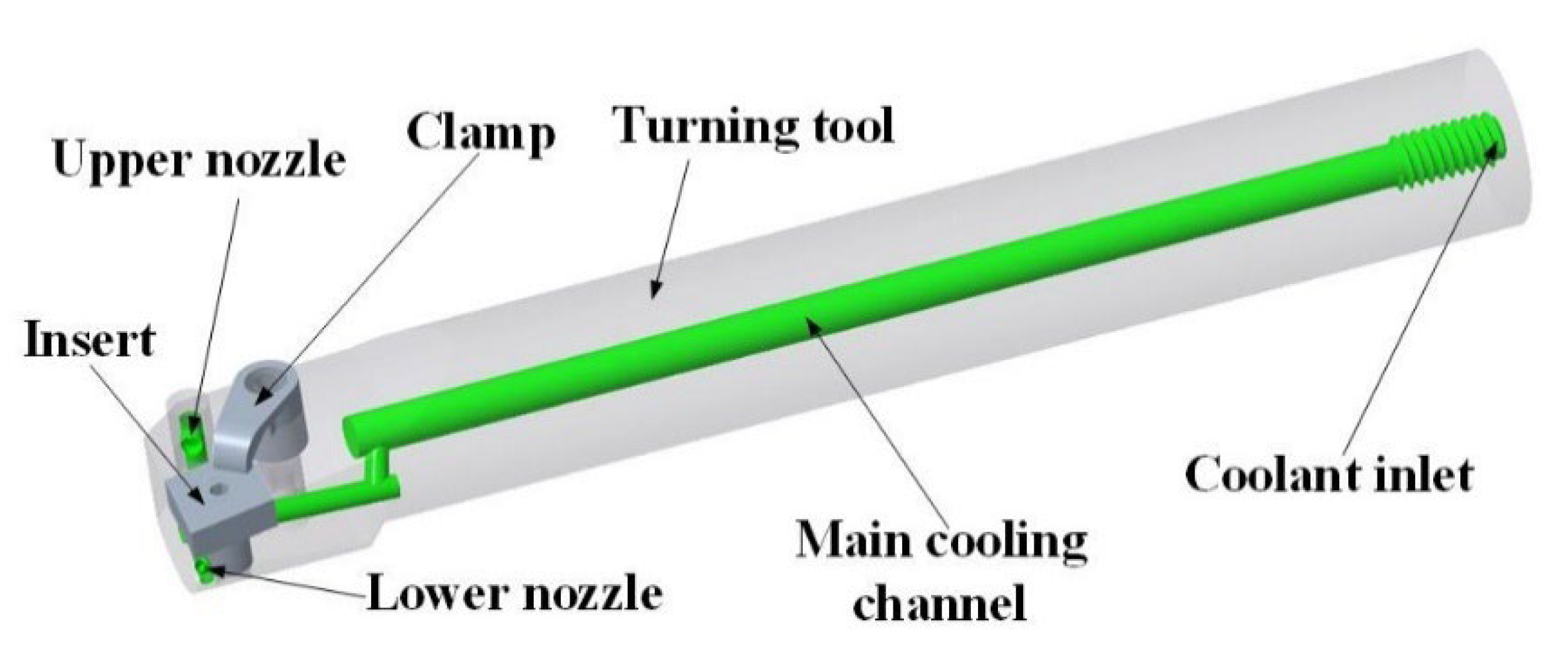
Figure 2.
The geometric model of numerical simulation for the internal spray cooling turning tool.
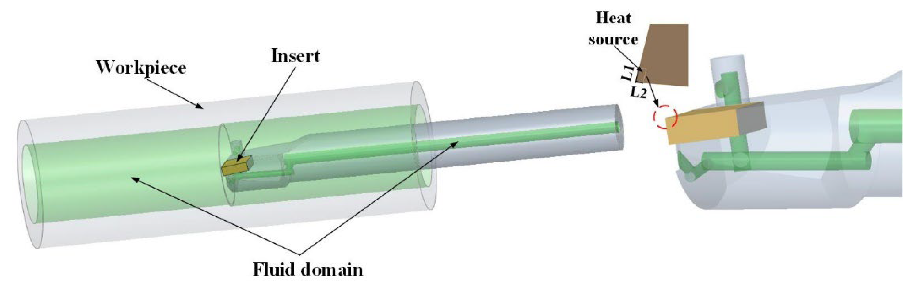
Figure 3.
Mesh independence calculating result.

Figure 4.
The mesh of simulation model of fluid-solid coupling heat transfer.
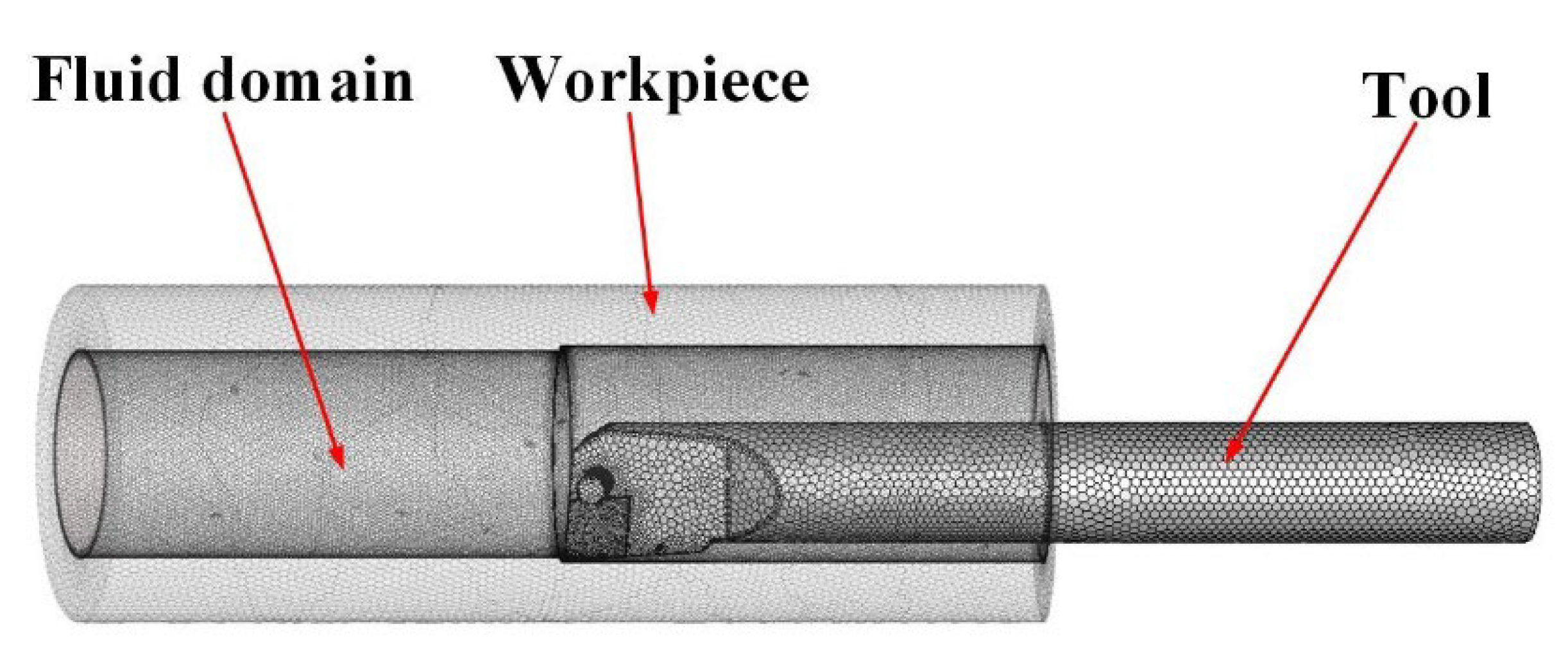
Figure 5.
Geometric parameters to be optimized of spray cooling structures.
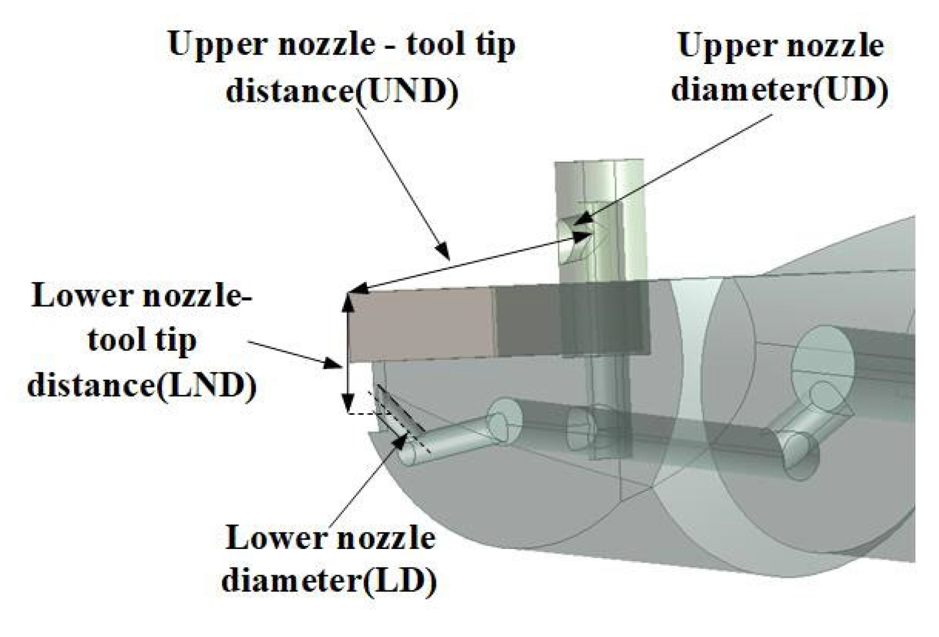
Figure 6.
The diagram of main effects of the three variables on maximum temperature. (a) Influence of UND to maximum temperature, (b) Influence of UD to maximum temperature, (c) Influence of LD to maximum temperature.
Figure 6.
The diagram of main effects of the three variables on maximum temperature. (a) Influence of UND to maximum temperature, (b) Influence of UD to maximum temperature, (c) Influence of LD to maximum temperature.
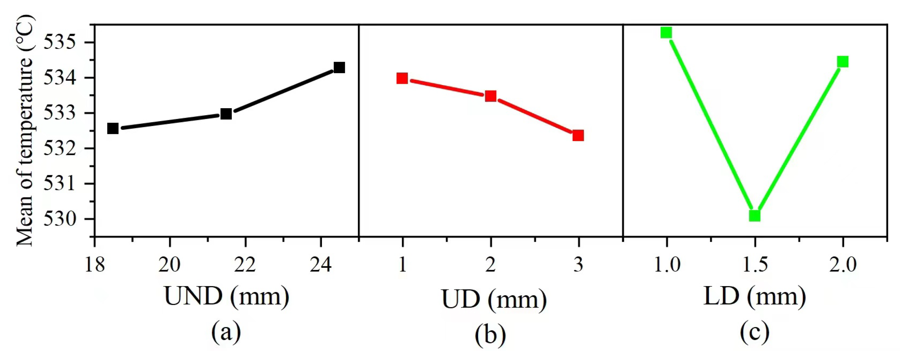
Figure 7.
Temperature contour and fluid pathline of the optimized tool. (a) Temperature contour of the optimized tool; (b) Fuid pathline of the internal spray cooling process.
Figure 7.
Temperature contour and fluid pathline of the optimized tool. (a) Temperature contour of the optimized tool; (b) Fuid pathline of the internal spray cooling process.

Figure 8.
Droplets velocity under different inlet pressures, (a) 0.1 MPa, (b) 0.2 MPa, (c) 0.3 MPa, (d) 0.4 MPa, (e) 0.5 MPa, (f) 0.6 MPa.
Figure 8.
Droplets velocity under different inlet pressures, (a) 0.1 MPa, (b) 0.2 MPa, (c) 0.3 MPa, (d) 0.4 MPa, (e) 0.5 MPa, (f) 0.6 MPa.
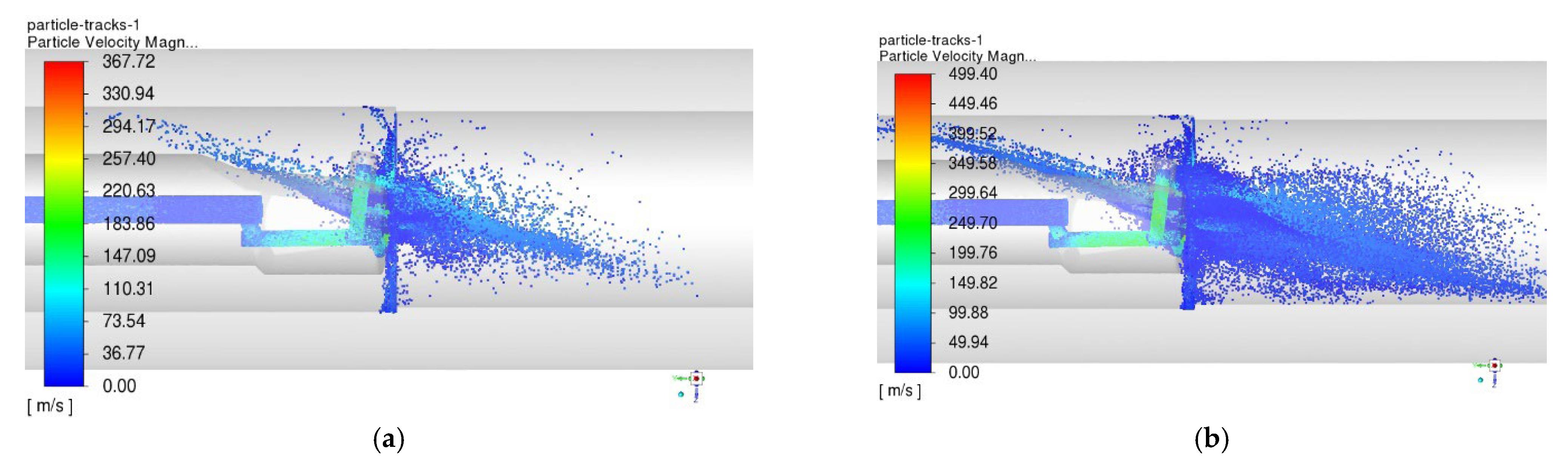

Figure 9.
Maximum temperatures of tool under different inlet pressures.
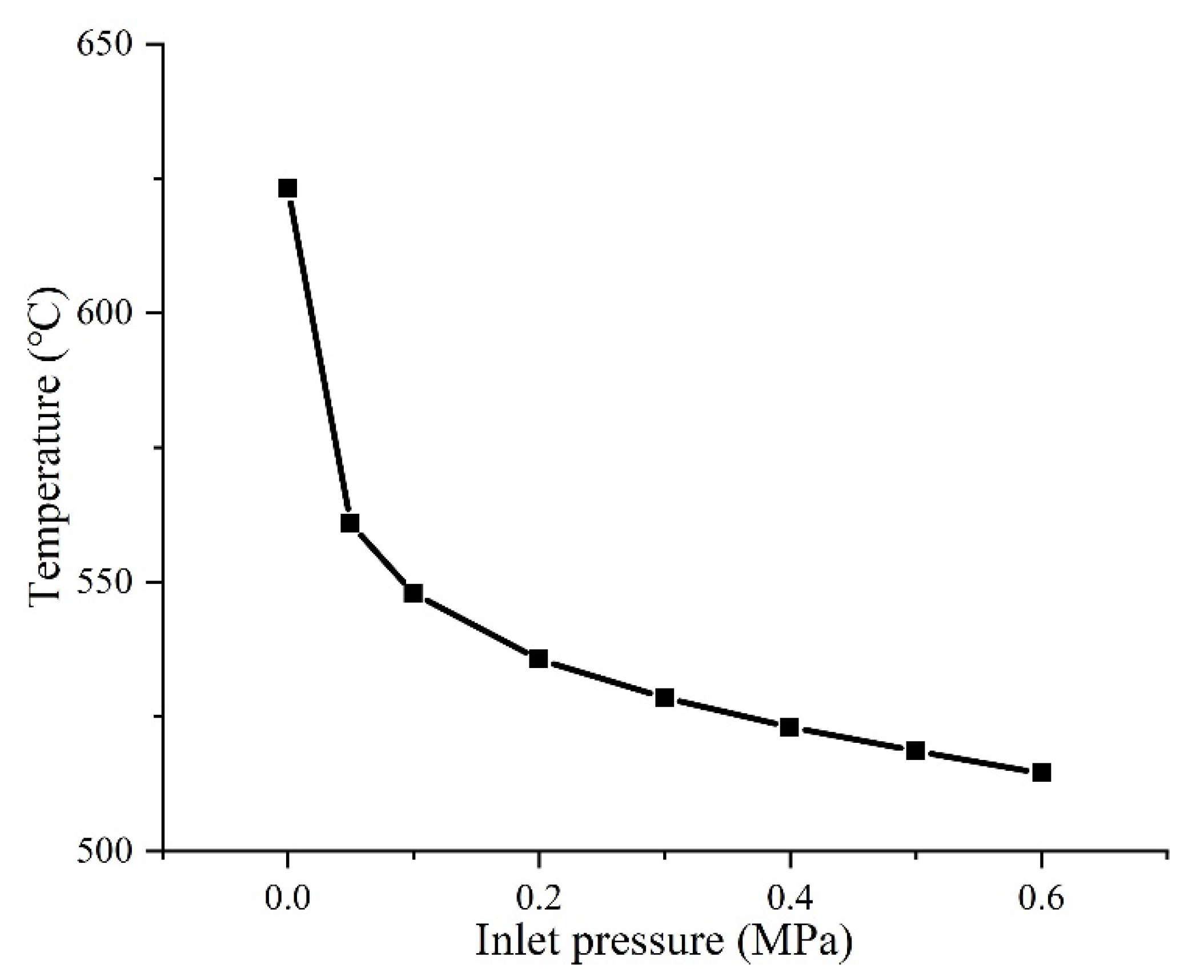
Figure 10.
The manufactured internal spray cooling turning tool and thermocouple position. (a) the internal spray cooling turning tool, (b) diagram of distance between thermocouple and main and minor cutting edges, (c) diagram of the distance between the thermocouple and the rake face.
Figure 10.
The manufactured internal spray cooling turning tool and thermocouple position. (a) the internal spray cooling turning tool, (b) diagram of distance between thermocouple and main and minor cutting edges, (c) diagram of the distance between the thermocouple and the rake face.
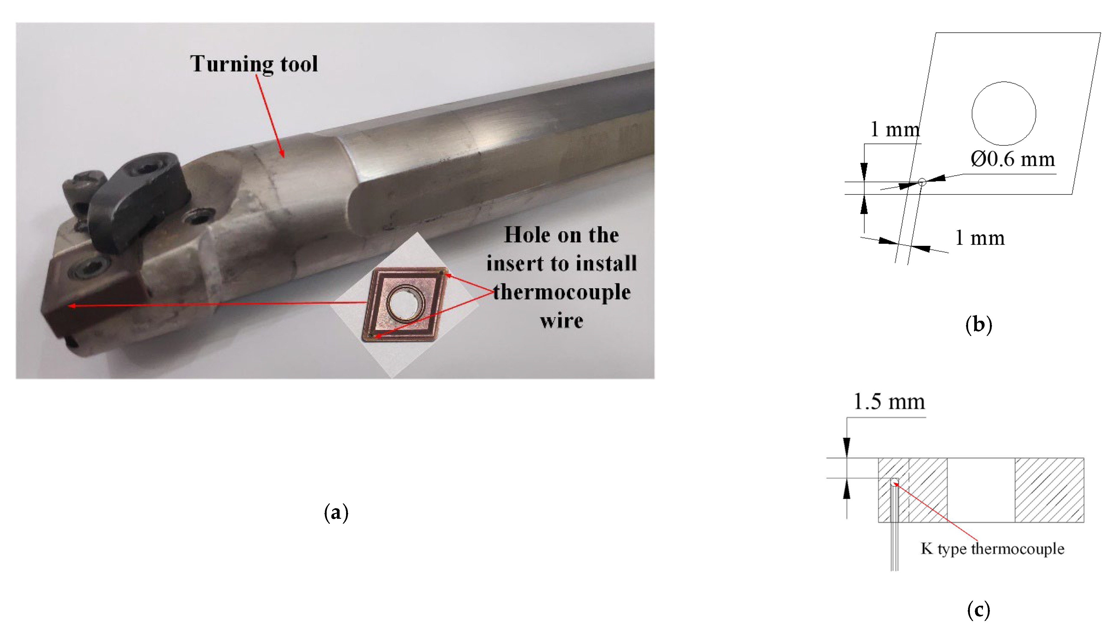
Figure 11.
Internal turning experimental platform.
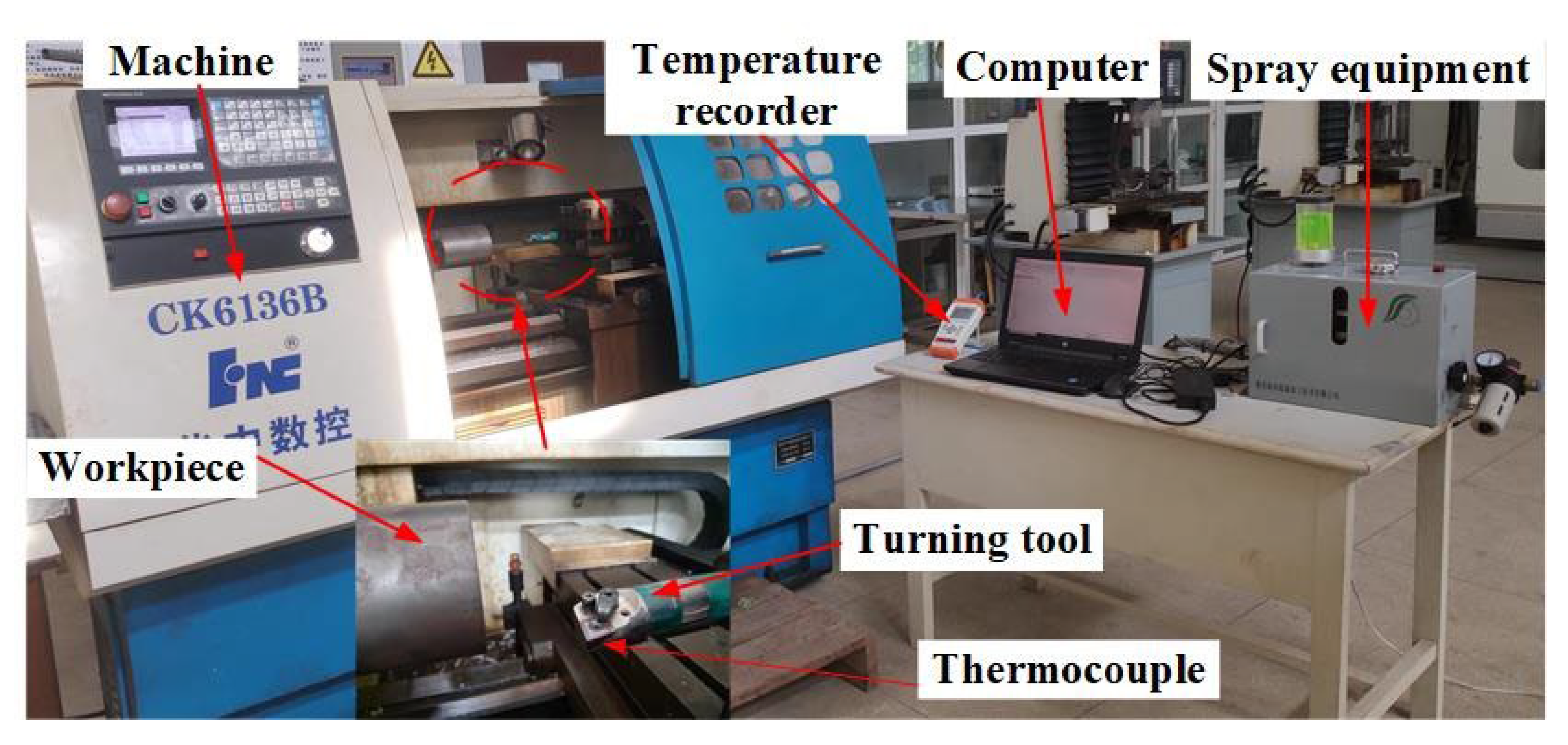
Figure 12.
Effect of cooling conditions on cutting temperature. (a) cutting temperature under different spray pressure, (b) the influence of cutting speed on cutting temperature under dry cutting and internal spray cooling.
Figure 12.
Effect of cooling conditions on cutting temperature. (a) cutting temperature under different spray pressure, (b) the influence of cutting speed on cutting temperature under dry cutting and internal spray cooling.
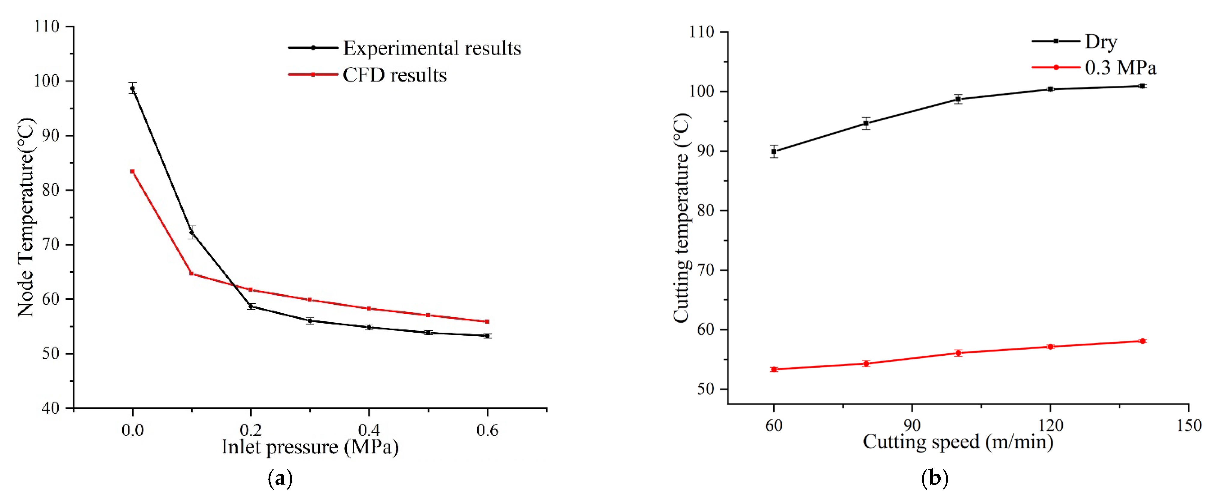
Figure 13.
Effect of cooling conditions on machined surface roughness of workpiece. (a) Surface roughness of workpiece under different spray pressure at a cutting speed of 100 m/min, (b) The spray cooling and dry cutting roughness at different cutting speeds.
Figure 13.
Effect of cooling conditions on machined surface roughness of workpiece. (a) Surface roughness of workpiece under different spray pressure at a cutting speed of 100 m/min, (b) The spray cooling and dry cutting roughness at different cutting speeds.
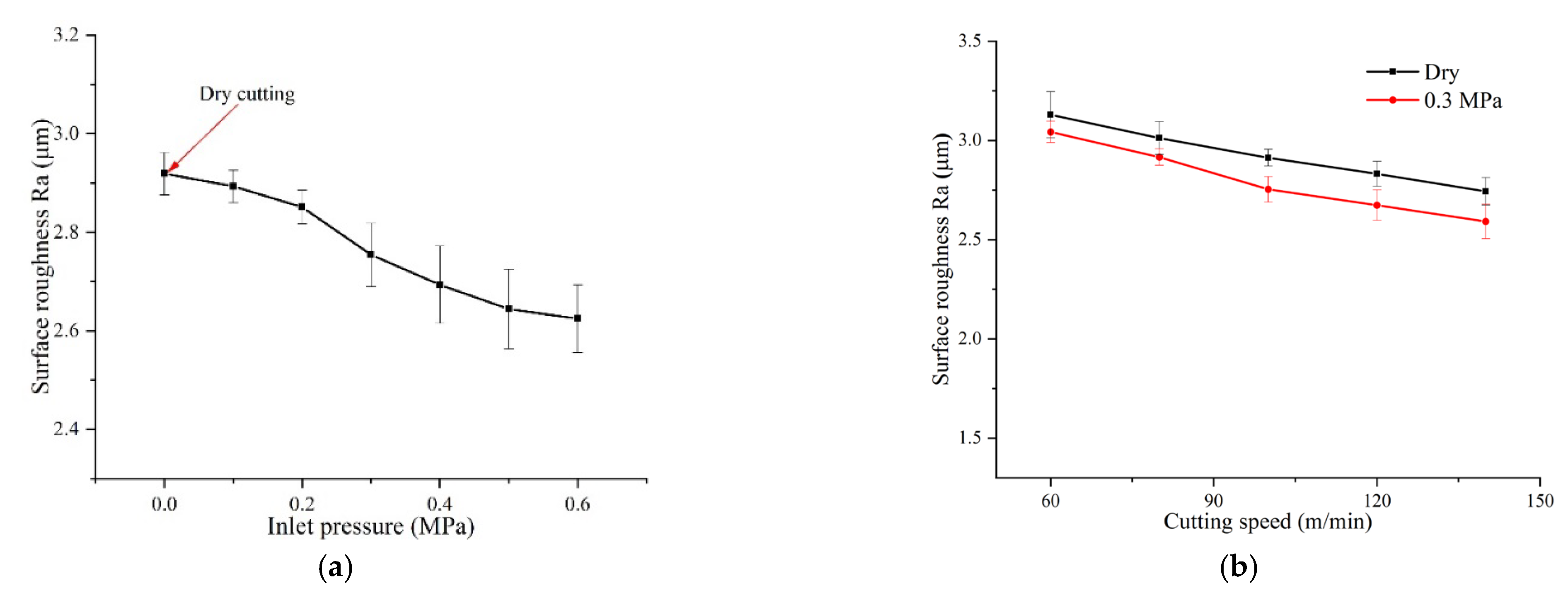
Figure 14.
Chip morphology under different cutting conditions. (a) Vc = 60 m/min-Dry, (b) Vc = 60 m/min−0.3 MPa, (c) Vc = 100 m/min-Dry, (d) Vc = 100 m/min−0.1 MPa, (e) Vc = 100 m/min−0.3 MPa, (f) Vc = 100 m/min−0.6 MPa, (g) Vc = 140 m/min-Dry, (h) Vc = 140 m/min−0.3 MPa.
Figure 14.
Chip morphology under different cutting conditions. (a) Vc = 60 m/min-Dry, (b) Vc = 60 m/min−0.3 MPa, (c) Vc = 100 m/min-Dry, (d) Vc = 100 m/min−0.1 MPa, (e) Vc = 100 m/min−0.3 MPa, (f) Vc = 100 m/min−0.6 MPa, (g) Vc = 140 m/min-Dry, (h) Vc = 140 m/min−0.3 MPa.


Table 1.
Simulation parameters.
| Variable | Value | Variable | Value |
|---|---|---|---|
| Density of insert (kg/m3) | 14,900 | Heat flux on contact area (W/mm2) | 40 |
| Thermal conductivity of insert (W/m∙K) | 52.3 | initial temperature (°C) | 20 |
| Specific heat of insert (J/kg∙K) | 302 | Specific heat of water (J/kg·K) | 4182 |
| Density of toolholder (kg/m3) | 7850 | Viscosity of water (kg/m·s) | 0.001 |
| Thermal conductivity of toolholder (W/m∙K) | 16.3 | Density of water (kg/m3) | 998.2 |
| Specific heat of toolholder (J/kg∙K) | 502 | Thermal conductivity of water (W/m·K) | 0.6 |
| Tool-chip contact area (L1 mm × L2 mm) | 1 × 0.5 | Inlet pressure of spray cooling (MPa) | 0.3 |
Table 2.
List of the geometric design parameters and their levels.
| Parameters | Levels | |||
|---|---|---|---|---|
| 1 | 2 | 3 | ||
| A | UND (mm) | 18.5 | 21.5 | 24.5 |
| B | UD (mm) | 1 | 2 | 3 |
| C | LD (mm) | 1 | 1.5 | 2 |
Table 3.
Simulation results and range analysis of L9(34) orthogonal test.
| No. | Upper Nozzle–Tool Tip Distance (A) /mm | Upper Nozzle Diameter (B) /mm | Lower Nozzle Diameter (C) /mm | Maximum Temperature/°C |
|---|---|---|---|---|
| 1 | 18.5 | 1 | 1 | 536.19 |
| 2 | 18.5 | 2 | 1.5 | 529.99 |
| 3 | 18.5 | 3 | 2 | 531.47 |
| 4 | 21.5 | 1 | 1.5 | 529.14 |
| 5 | 21.5 | 2 | 2 | 535.29 |
| 6 | 21.5 | 3 | 1 | 534.47 |
| 7 | 24.5 | 1 | 2 | 536.58 |
| 8 | 24.5 | 2 | 1 | 535.12 |
| 9 | 24.5 | 3 | 1.5 | 531.14 |
| K1 | 532.55 | 533.97 | 535.26 | Ki is the average value of maximum temperature at each factor level; R is the value of range |
| K2 | 532.96 | 533.47 | 530.09 | |
| K3 | 534.28 | 532.36 | 534.44 | |
| R | 1.73 | 1.61 | 5.17 |
Table 4.
The parameters of cutting experiments.
| Parameter | Value |
|---|---|
| Cutting speed (m/min) | 60, 80, 100, 120, 140 |
| Feed rate (mm/r) | 0.1 |
| Depth of cut (mm) | 0.5 |
| Cooling conditions | 0.1–0.6 MPa/dry cutting |
| Coolant flow rate (mL/h) | 50 |
Publisher’s Note: MDPI stays neutral with regard to jurisdictional claims in published maps and institutional affiliations. |
© 2022 by the authors. Licensee MDPI, Basel, Switzerland. This article is an open access article distributed under the terms and conditions of the Creative Commons Attribution (CC BY) license (https://creativecommons.org/licenses/by/4.0/).
Share and Cite
MDPI and ACS Style
Liu, L.; Shu, S.; Li, H.; Chen, X. Design, Optimization and Cutting Performance Evaluation of an Internal Spray Cooling Turning Tool. Coatings 2022, 12, 1141. https://doi.org/10.3390/coatings12081141
AMA Style
Liu L, Shu S, Li H, Chen X. Design, Optimization and Cutting Performance Evaluation of an Internal Spray Cooling Turning Tool. Coatings. 2022; 12(8):1141. https://doi.org/10.3390/coatings12081141
Chicago/Turabian StyleLiu, Leping, Shengrong Shu, Huimin Li, and Xuan Chen. 2022. "Design, Optimization and Cutting Performance Evaluation of an Internal Spray Cooling Turning Tool" Coatings 12, no. 8: 1141. https://doi.org/10.3390/coatings12081141
Note that from the first issue of 2016, this journal uses article numbers instead of page numbers. See further details here.