Article

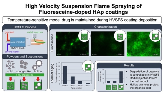
Deposition of Fluoresceine-Doped HAp Coatings via High-Velocity Suspension Flame Spraying

Institute for Manufacturing Technologies of Ceramic Components and Composites (IMTCCC), University of Stuttgart, Allmandring 7b, 70569 Stuttgart, Germany
*
Author to whom correspondence should be addressed.
Coatings 2022, 12(9), 1251; https://doi.org/10.3390/coatings12091251
Submission received: 3 August 2022 / Revised: 18 August 2022 / Accepted: 22 August 2022 / Published: 26 August 2022
(This article belongs to the Special Issue Development of Hydroxyapatite Coatings)

Abstract

:
In current medicine, joint revision surgery plays an important role in the treatment of degenerative joint diseases. Infections of the artificial joints are an iatrogenic, accompanying symptom after joint replacement procedures. A new approach is to functionalize the bioactive coatings of the implants by infiltrating them with anti-inflammatory drugs. This work aims at a one-step approach in manufacturing drug-doped, porous hydroxyapatite coatings by high-velocity suspension flame spraying (HVSFS). Thermal exposure of the temperature-sensitive drugs is critical. Therefore, a new process setup, combining one axial and one radial suspension line, is used for coating deposition. The lower dwell time of the suspension in the flame through radial injection helps in controlling the temperature exposition of the contained drug to the flame. Additionally, the influence of the powder morphology, used as a carrier for the drug in the suspension, is investigated by carrying out spray experiments with suspensions from three different granule types. To analyze the temperature exposition within the coating process, fluoresceine was used as a model drug, as the decomposition of the organic, fluorescing molecules can be easily controlled by fluorescence intensity measurements. It could be shown that the deposition of temperature-sensitive organic molecules is possible without degrading the molecular structure by a modified HVSFS process. This knowledge offers new possibilities in the cost-effective one-step manufacturing of functionalized, anti-inflammatory bioceramic coatings on orthopaedic implants.

Graphical Abstract

1. Introduction

Joint revision surgery today plays an important role in ensuring the quality of life of patients with degenerative joint diseases. Even if there are high success rates, it comes to complications in up to 10 percent of endoprosthetic hip replacements. If these complications are subdivided, the periprosthetic joint infection ranks as the third-highest concern, with an incidence of 15.3 percent. The total risk to undergo a periprosthetic joint infection after total hip arthroplasty is estimated at 0.2 to 2 percent, resumed Otto-Lambertz et al. from different publications [1].
Although the percentage of occurring joint infections seems quite low, the relevance of the problem is high due to high absolute numbers of joint revision surgery (e.g., 240.000 total hip arthroplasties in Germany in 2018 [2]).
Once a prosthesis is infected, the systemic use of orally administered antibiotics—as performed prophylactically in advance of the surgery—does not sufficiently treat the joint infection, because the pathogen is encapsulated by a mucus layer. Only repeated surgery with removal of the infected tissue and the in-situ deposition of suitable antibiotics helps to cure the periprosthetic infection [3,4].
To prevent the patients from risky additional surgical procedures, the implants should already contain suitable antibiotics that are released, locally restricted, over a long-term period after surgery. A possibility therefore is offered, because state-of-the-art implants are manufactured from titanium or cobalt-chromium alloys and plasma spray coated by porous titanium or hydroxyapatite (HAp) [5]. The latter shows a good usability as a drug carrier, as Yamashita et al. could demonstrate a controlled and long-term release of antibiotics from infiltered hydroxyapatite [4].
Research on plasma sprayed hydroxyapatite coatings on Ti alloy bone implants was further intensified [6,7,8] and discussed in review articles [9,10]. However, besides spraying regular powders suitable for standard plasma spraying, a new process type evolved: suspension spraying.
Research activities oriented towards liquid precursor and suspension plasma spraying. Both were found to be well suited for spraying nano-sized and micron-sized HAp powders as a dispersion [11,12,13,14].
High-velocity flame spraying using suspensions as a feedstock offers the possibility to spray particles with significantly higher kinetic energy [15,16,17]. This process soon came into focus especially for spraying bioactive glasses, forming rather dense and well-adherent coatings [18,19,20]. Furthermore, suspension spraying in general offers the possibility to mix different materials or add metal salts or precursors as a dopant [21]. This work has marked the beginning of a new concept where chemical agents are added to a bioactive coating meaning to be released in vivo.
For three-dimensional scaffolds this concept is already well known and has been studied since many years [22]. Their purpose can be of a diverse nature: release of antibacterial substances near the implant interface as described in [21] or a controlled stimulation of bone ingrowth and blood vessel formation.
Now, the aim is to modify the persisting process in order to integrate a model drug as a secondary phase into a porous hydroxyapatite coating. The main challenge in depositing an organic drug by thermal spraying is the high thermal impact the substance is exposed to. Especially organic molecules such as antibiotics tend to degrade at temperature levels below 300 °C [23], being relatively low in the context of thermal spraying.
Venturi/Hussain already made some efforts in depositing temperature-sensitive products by HVSFS. They succeeded in depositing graphene nanoplatelets that start degrading at 250 °C by a radial injection of the suspension into the flame and investigated basic principles for the successful radial suspension injection [24].
In this work, we used a HVSFS process with a combination of one axial and one radial injection line. This configuration has been used in advance for the deposition of thermally sensitive AlN coatings [25]. In general, this setup offers new possibilities in depositing complex material systems. In our example, a hydroxyapatite matrix is sprayed through the axial injection of an aqueous hydroxyapatite suspension into the combustion chamber. The temperature-sensitive model drug suspension was radially injected to shorten the interaction time between flame and organics.
Fluoresceine was used as a model drug, which has already proven to be an easy-analyzable chemical compound to demonstrate that a process temperature of 300 °C was undercut in 3D printing experiments [26]. The degradation temperature of fluoresceine is around 320 °C [27] and consequently in the region of the degradation temperature of drugs like antibiotics.
In the work presented, the strategy to minimize decomposition was to encapsulate the fluoresceine in hollow hydroxyapatite spheres that were produced by means of spray drying. In the cavity of the granules a better thermal protection of the fluoresceine is anticipated due to the thermal inertia of the relatively big granules and because there is no direct exposition of the fluoresceine to the flame.

2. Materials and Methods

To verify the assumption of better thermal protection of the fluoresceine within hollow granules, comparative coating experiments were carried out with three different radially injected suspension preparations based on three different powder types. The axially injected HAp suspension is intended to build up the matrix of the created coating, thereby embedding and anchoring the radially inserted particles. The formulation of the suspension axially applied remained the same for all coating experiments. The raw hydroxyapatite powder used within the experiments of this publication is delivered from Chemische Fabrik Budenheim KG (Budenheim, Germany). One suspension for radial injection was based on the Budenheim raw material (P1), the others on two different custom-made powder types manufactured through spray drying and calcined in the following. Both custom-made powders were spray-dried from suspension formulations based on the Budenheim raw material. One type of powder had a sponge-like structure (P2) showing a highly micro-porous internal structure. The other sprayed powder (P3) consisted mainly of hollow granules with an approximately closed outer shell and one central void. All suspensions for radial injection contained fluoresceine as a temperature-sensitive marker. For further information on chemical and physical properties of hydroxyapatite and fluoresceine, please refer to [27,28], respectively.

2.1. Suspension Preparation

All suspensions used in this work were based on an aqueous formulation. Suspension S0 refers to the pure HAp suspension. Suspension formulations named S1, S2 and S3 contain two components: the model drug fluoresceine and HAp particles with a defined morphology in order to prevent the heat-sensitive fluoresceine from direct thermal exposure to the flame.

2.1.1. HAp Suspension for Axial Injection

Suspension S0 was used for axial injection as further explained in the next section. Raw hydroxyapatite (HAp) powder was ball-milled until a d90 value of 5µm was reached. Then it was mixed with deionized water and 3 wt.% of a stabilizing agent based on phosphonate was added under continuous stirring. The solid content was set to 10 wt.%.

2.1.2. Fluoresceine-Doped HAp Suspensions for Radial Injection

Three different aqueous suspensions (S1–S3) were prepared for the external radial injection. In Table 1, their composition is displayed. The difference between the three suspensions is the powder they are based on. Suspension 1 (S1) is based on the raw HAp powder P1, suspension 2 (S2) and suspension 3 (S3) are based on the respective custom-made spray-dried powders P2 and P3. After spray drying, the powders P2 and P3 were calcined at 600 °C for one hour to improve the stability of the particles’ morphology in an aqueous suspension.
All suspensions were stabilized using 8 wt.% of a phosphonate-based stabilizing agent. To control the sedimentation behaviour of the suspensions, 3 wt.% of solute modified urea was added as rheology additive. After dispersing the ceramic powder, the suspensions were infiltrated with fluoresceine sodium (Fluoresceine Sodium (C.I. 45350) for analysis, Acid Yellow 73, Uranine, AppliChem GmbH, Darmstadt, Germany). The same concentration of 1.255 g fluoresceine per mole hydroxyapatite—respectively 0.25 wt.% fluoresceine—was used for all suspensions. The fluoresceine was simply dissolved in the water dispersant. Following the dispersing of the HAp powder into the water containing dissolved fluoresceine, the suspension was rotationally agitated in a bottle to homogenize the distribution of the fluoresceine within the calcined agglomerates.
After preparation, all suspensions were sieved through a 90 μm sieve prior to the coating experiments to prevent clogging of the nozzle by large single agglomerates.

2.2. Coating Deposition

The coatings were deposited on titanium grade-2 specimens (ARA-T Advance GmbH, Dinslaken, Germany). Prior to coating, the samples were grit-blasted using F100 corundum at a pressure of 6 bar and subsequently cleaned with acetone in an ultrasonic bath. Finally, the samples were weighed to determine the net weight of the substrate.
A modified TopGun-G system (GTV Verschleißschutz, Luckenbach, Germany) was used for this work. The torch was mounted on a six-axis robot to perform controlled meander movement with an offset of 3 mm and a spraying distance of 120 mm. Five meander cycles were performed in front of the substrate surface during the HVSFS deposition process. The relative surface speed was set to 750 mm/s. All tests were run with a 22-8-78 combustion chamber. An axial pressurized air cooling with two nozzles at the left and right side of the torch axis was used.
The TopGun is equipped with two separate injection lines (refer to Figure 1). One line using an internal injector is feeding axially into the combustion chamber. The second one is operated radially and feeding downstream into the free expanding gas current behind the nozzle exit. Constructively, the external injector (Baureihe 544, Lechler GmbH, Metzingen, Germany) was mounted centrally above the HVSFS torch nozzle and positioned at a horizontal distance dx of 10 mm in front of the nozzle exit at an angle Φr of 15° downstream (refer to Figure 1). The vertical distance dy off the torch axis was 37 mm. Both nozzles are orifice nozzles with a diameter of 0.5 mm, delivering a continuous stream of suspension. Axial feed rate was set to 40 mL/min, radial feed rate was set to 120 mL/min.
As mentioned, earlier, suspension S0 was always used for axial injection; S1–S3 were alternatively used for radial injection. An overview of all relevant spray parameters are given in Table 2. Stoichiometry was kept constant for all spray experiments at λ = 0.63. Samples C1–C3-3 are the samples analyzed in detail. Sample R0 was only sprayed axially and served as a reference for hardness and deposition efficiency.
After completion of the coating process, the coated samples were weighed in order to calculate the deposition efficiency according to DIN EN ISO 17836. The surface temperature during the HVSFS process was constantly monitored via a thermographic camera (VarioSCAN 3 (LW), InfraTec GmbH, Dresden, Germany).

2.3. Feedstock and Coating Characterization

The particle size distributions of the initial powder and the suspension prior to thermal spraying were measured using a laser granulometer Mastersizer 3000 (Malvern Instruments, Malvern, UK). The raw powder was measured under ultrasonic agitation to prevent agglomeration and with the assumption of non-spheroidal particle morphology for data analysis. For the spray-dried powders, measuring conditions were changed. They were measured without ultrasonic agitation to prevent destabilizing of the hollow granules or sponge-like structures. Spheroidal particles were assumed for data analysis as spray-dried powders usually show spheroidal shape. The particle size distributions of the wet-milled powder for suspension S0 and the radially injected suspensions S1 to S3 were measured by dispersing some droplets of the suspension into the aqueous dispersion unit of the Mastersizer. Suspensions S0 and S1 from the ball-milled and the as-supplied powders were measured under ultrasonic agitation and the assumption of non-spheroidal particles, according to the respective powders. Consequently, suspensions from powders P2 and P3 were measured without ultrasonication and under the assumption of spheroidal particles.
Coating microstructures were observed through an optical microscope MeF4M (Leica GmbH, Wetzlar, Germany) in bright field. Pictures were taken and analyzed by software A4I analysis (A4I, London, UK). Coating thicknesses were characterized according to DIN EN ISO 1463:2021-08 by measuring ten single-coating thickness values and calculating the average value and standard deviation of ten individual measurements.
Further details of the microstructures were observed using a field-emission scanning electron microscope (SEM) S-800 (Hitachi High-Technologies Corporation, Tokyo, Japan). Cross-section samples were sputtered with carbon before SEM examination. Powders were characterized using a Jeol NeoScope JCM-5000 (Jeol Ltd., Akishimi, Tokyo, Japan), as the lower vacuum of this machine allows examination of the non-conductive powders without sputtering.
To determine the elemental composition of the coating microstructure, wavelength dispersive X-ray spectroscopy (WDX) measurements were carried out using a SX 100 electron microprobe (Cameca, SAS, Gennevilliers, France). The element distribution of the different phases within the cross-section was visualized by a mapping of the relevant elements carbon (C), phosphorus (P) and calcium (Ca).
All samples underwent fluorescence microscopy of the specimen surface and the cross section in order to characterize the fluorescence properties of the coating. An inverted optical microscope Axiovert 200M (Carl Zeiss AG, Oberkochen, Germany) was used with a UV light source and a FITC filter set with excitation between 450 nm and 490 nm and emission between 515 nm and 565 nm. The superficial fluorescence emission was documented at the same exposure for all samples, so that the emission intensity can be compared quantitatively. The cross sections were all documented using the automatic exposure at the same threshold. Nevertheless, there cannot be made any quantitative statement concerning the fluorescence emission intensity regarding the exposure times. The differences in fluorescence emission of different specimens are superimposed by the varying coating thicknesses of the different specimens, leading to shorter exposures for higher coating thicknesses with larger fluorescing areas.
Superficial fluorescence images were analyzed using the software ZEN 3.0 blue edition (Carl Zeiss Microscopy GmbH, Oberkochen, Germany). Average intensity of the camera channel was determined by a grayscale analysis of all image pixels and following calculation of the average gray value. As only one fluorescence signal was detectable, the average intensity of the camera channel can be directly taken as mean fluorescence intensity (MFI).
By analyzing the MFI values of the different specimen surfaces and under the condition that all images were taken at the same exposure, a comparative quantifying of fluoresceine content of different coatings can be made. This allows conclusions from the influence of powder morphology and process parameters on the degradation of fluoresceine.
The thermal decomposition behaviour of the fluoresceine was investigated through thermal aging experiments of one coated sample (C3-3) with initially high fluorescence intensity. The specimen was cut into small test samples. Different samples were aged at 250 °C, 300 °C and 350 °C for one hour per sample. After thermal aging, the MFI value was determined through fluorescence imaging of the surface of every sample.
Vickers hardness was measured using a Fisherscope H100 (Helmut Fischer GmbH Institut für Elektronik und Messtechnik, Sindelfingen, Germany) microhardness tester. HV 0.01 scale was used in order to be within the DIN EN ISO 14577 standard for the thinnest of all coatings, which is sample C3-3. To enable direct comparability of the hardness values of all coatings, even the hardness of the thicker coatings was measured within the HV 0.01 scale. The measurement is force-regulated and the applied load of 0.01 N was performed for 20 s with a load and release time of 5 s. For each sample, ten imprints on the cross-section of the coating were made, the average hardness and its standard deviation were calculated.

3. Results

3.1. Powders

The particle size values are tabulated in Table 3. Particle outer morphologies as well as the inner microstructure of cross-sections were analyzed by SEM images and are displayed in the results section (see Figure 2).
The three powders used within this research differ clearly in morphology and particle size distribution (PSD). The raw material P1 is a fine powder with irregular morphology (Figure 2, P1). Cross-section shows that the powder exhibits some inner porosity. Slight agglomeration of the single granules is visible in the SEM image of the powder.
The sponge-like powder shows a mostly spherical morphology (Figure 2, P2). A low number of irregular-shaped particles is visible. Cross-section image shows the high, sponge-like porosity for the bigger particles. Smaller particles show lower porosity or appear completely solid. No agglomeration is visible in the SEM image of the powder.
The hollow spherical powder P3 shows a wide particle size distribution. The morphology of the powder is close to spherical. Whereas larger particles show an opening with inward edges (Figure 2, P3), smaller particles appear spherical and solid. The cross-section image confirms that larger particles have an internal void, whereas smaller particles are solid. Most of the voids of the large particles are filled with resin but some air voids exist that could not be penetrated by the resin.

3.2. Suspensions Used for Coating Experiments

The particle size distributions of the suspensions for the axial and radial injection line were measured. Particle size distributions and corresponding particle size values are displayed in Figure 3.
The axially applied suspension S0 shows a narrow particle size distribution. A slight shoulder on the left side of the curve (refer to marking a) is visible. Regarding the PSD curve of suspension S1, based on the raw powder P1, it is visible that the d90 value of suspension S1 increased by 2 μm compared to the dry powder P1 (see Table 3), whereas the d10 and d50 values remained constant. A slight shoulder on the right side of the curve (refer to marking b) is visible. The particle sizes of the sponge-like powder P2 in the suspension S2 remained exactly constant, compared to the dry powder P2. A shoulder on the left side of the curve (refer to marking c) is visible. Different to that, the particle size values of suspension S3 decreased slightly compared to the dry powder P3. A secondary peak around 0.1 μm particle size appears (refer to marking d).

3.3. Properties of the Deposited Coatings

The coating thicknesses and deposition efficiencies of all coatings were determined. Values are listed in Table 4. All deposition efficiency values determine the overall coating efficiency referring to the entirety of axially and radially injected feedstocks. The reference probe R0 has the highest hardness and deposition efficiency. It is obvious that coating thickness and hence deposition efficiency decrease with increasing particle size of the deposited feedstock (samples C1, C2 and C3-1). Additionally, there is a trend that coating thickness and deposition efficiency decrease with decreasing total gas mass flow and hence lower-energy coating conditions (samples C3-1, C3-2 and C3-3). The hardness has the lowest value for coating C1 made from the raw material supplied by Budenheim and the highest value for coating C2 made from the sponge-like materials. For the coating C3, sprayed from the hollow granules at different gas mass flow conditions, the hardness decreases with decreasing total gas mass flow and hence lower flame energy during deposition of the coating.

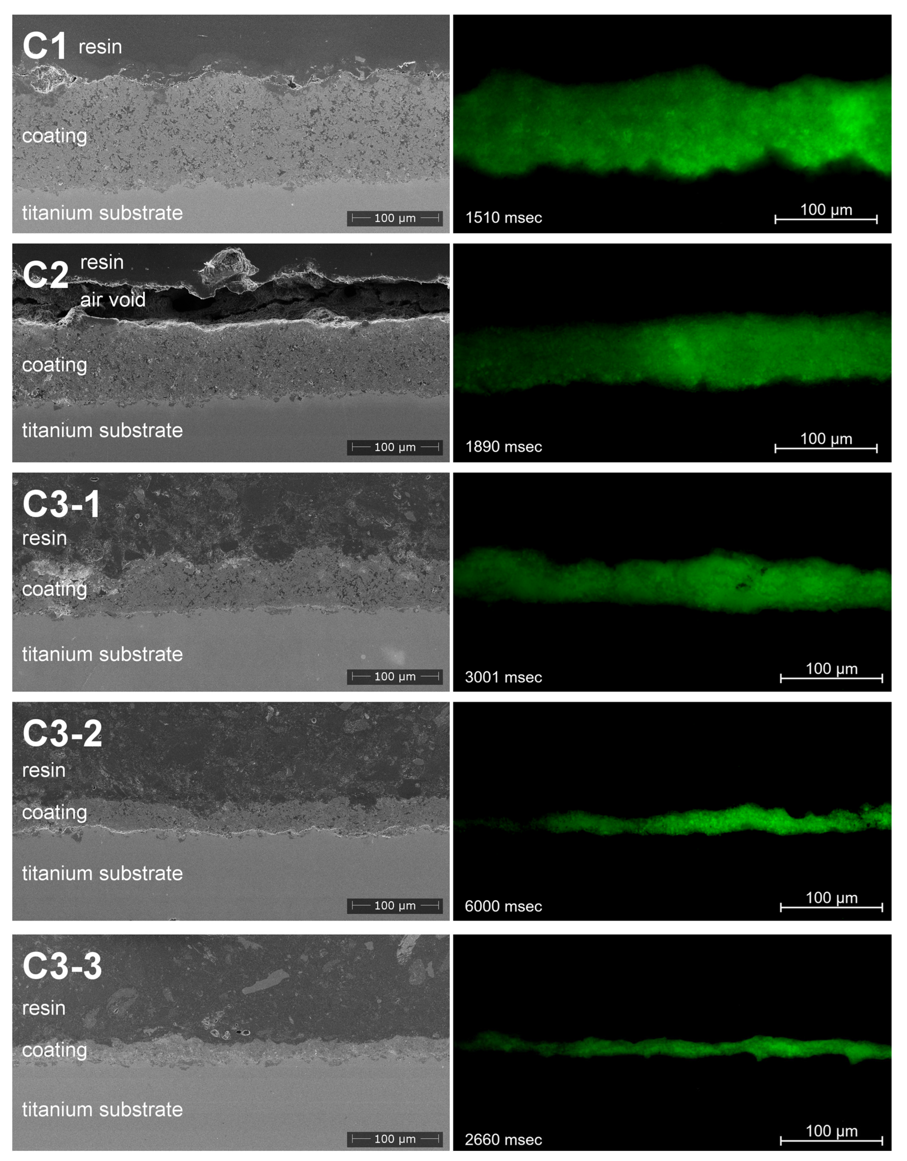
3.4. Coating Morphology

Figure 4 gives an overview of the coating microstructure of all coated samples analyzed in detail. Coating C1 from the raw material shows the finest and most homogeneous composition. The coating structure of coating C2 also appears homogeneous and regular. Both coatings have homogeneous coating thickness and hence macroscopically smooth surfaces. All C3 coatings from the radially injected suspension based on the big, hollow granules show more irregular microstructure with large coherent, darker areas and finer intermingling bright areas (see also BSE image in Figure 5). Macroscopic porosity is low for coating C3-1 and the surface exhibits a rough and irregular topography. The surfaces of coatings C3-2 and C3-3 have also rough topography (refer to Figure 4).
All coatings show fluorescence emission within the complete cross-sectional area (Figure 4). The fluorescence emission has higher intensity at some spots and decreases versus the left edge of each microscopy image. The exposures of all images differ, as they were set automatically for each image to obtain optimal exposure conditions for imaging.
A reference specimen fabricated by spraying with no additional radial suspension injection showed no fluorescence emission.

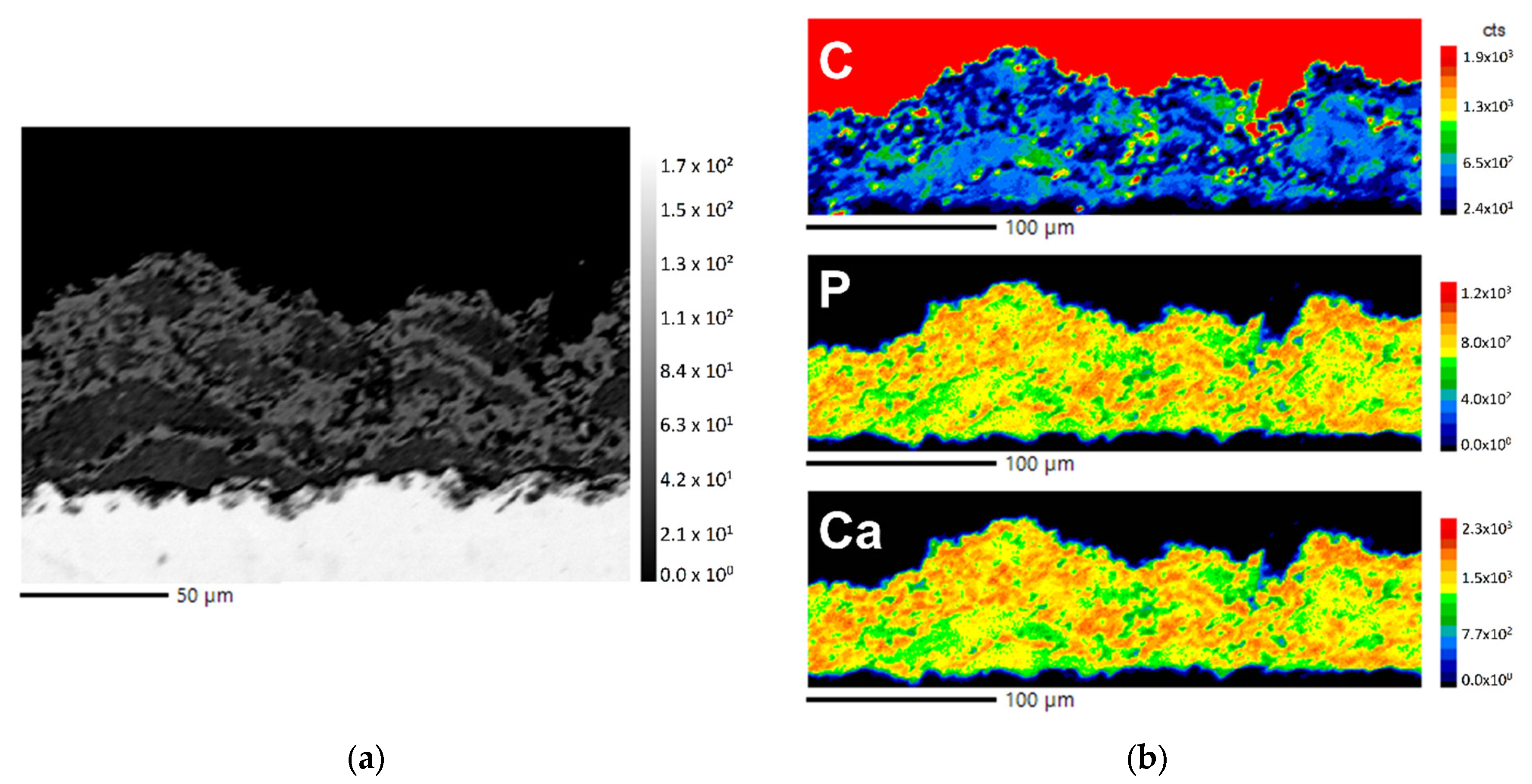
3.5. Element Analysis

The wavelength dispersive X-ray spectroscopy analysis (WDX) of the cross-section of coating C3-1 shows two different phases. The phase component appearing darker in the BSE image shows an increased content of carbon while there is a lack of calcium and phosphorus compared to the phase appearing brighter in the BSE image. The quantification results of the elemental distribution of calcium and phosphorus are congruent and inversely proportional to the distribution of carbon.

3.6. Fluorescence Properties in Correlation to Suspension Formulation and Process Parameters

The influence of the powder morphology on the fluoresceine content was studied by depositing coatings with three different radially injected suspensions based on three different powders (see Figure 6a). As all process parameters were kept constant, similar superficial substrate temperatures were measured for all three coating experiments. The fluoresceine content, measured as superficial mean fluorescence intensity (MFI) of each substrate, is similar and relatively low for suspensions S1 and S2 based on the raw powder (P1) and sponge-like granules (P2). The coating sprayed from suspension S3 based on the hollow granules (P3) shows a significantly higher MFI at the surface of the specimen.
In a second experiment, the gas mass flow was varied at three different levels (see Figure 6b). Spraying suspension S3 at varied gas mass flows and consequently varied flame energies leads to different superficial substrate temperatures. These temperatures increase with increasing gas mass flow due to the higher flame enthalpy. Accordingly, the MFI value shows a correlation reciprocal to the surface temperature of the substrate. The coating sprayed at lowest enthalpy, showing the lowest heating of the substrate, preserves the highest content of active fluoresceine. Consequently, this coating shows the highest mean fluorescence intensity.

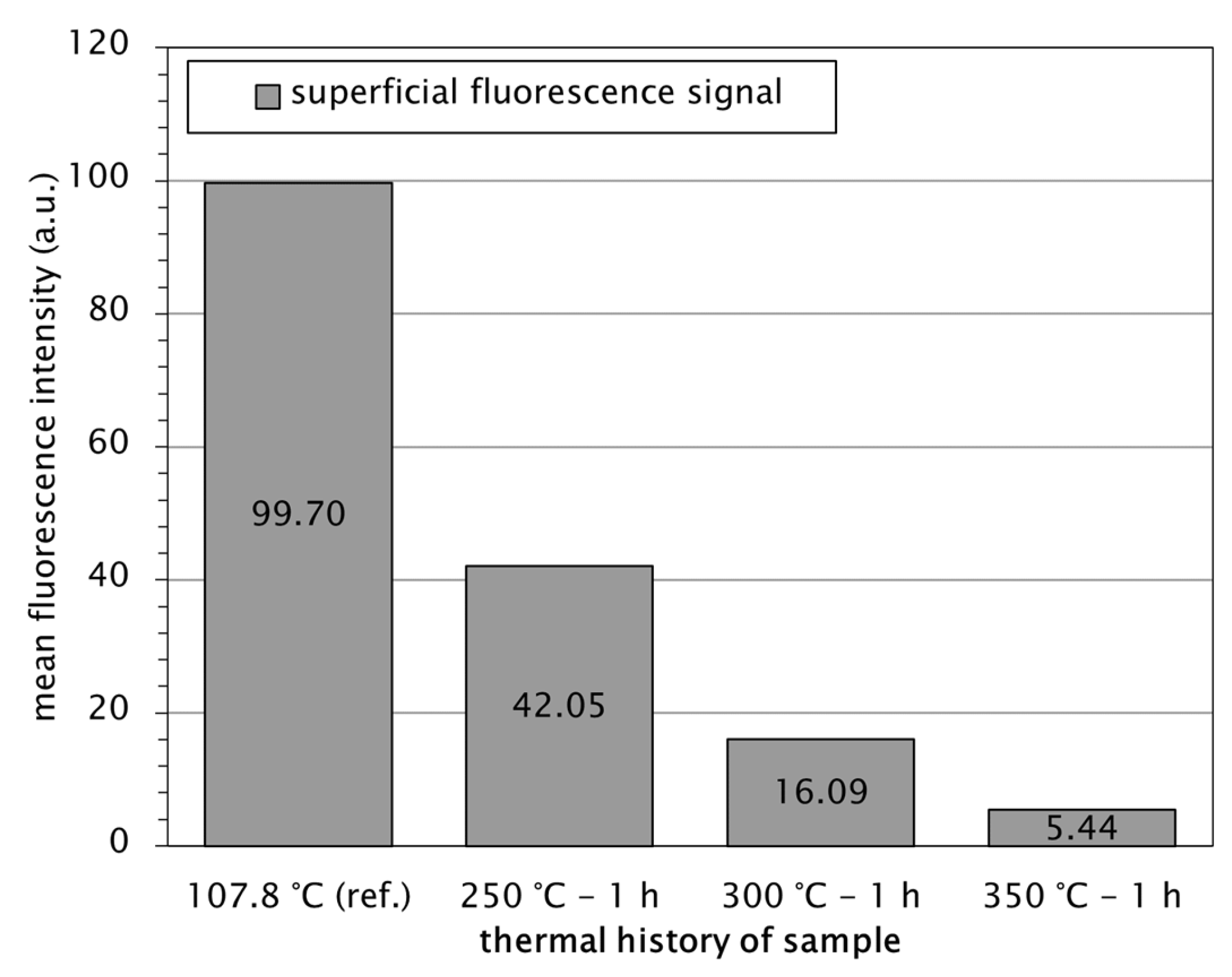
3.7. Thermal Degradation Behaviour of Fluoresceine

To investigate the decomposition behaviour of fluoresceine, the sample C3-3 with the highest fluorescence intensity after coating was thermally aged at different temperature conditions. A continuous decrease of the MFI signal of the specimen’s surface is detectable with increasing aging temperatures (Figure 7). At 250 °C aging temperature, the fluorescence intensity has lowered by more than the half compared to the unaged coating C3-3.

4. Discussion

4.1. Suspension Preparation

Processable suspensions from all powder types could be successfully prepared. Ball-milling of the raw powder in suspension S0 leads to a suspension with a very narrow particle size distribution. Formation of fine powder fragments was responsible for a small accumulation of fine particles below 1 µm (see Figure 3, S0, marking a). Dispersing the raw powder P1 into the aqueous suspension S1 leads to slight agglomeration of particles, which explains the shoulder below 100 μm particle size in the PSD curve (see Figure 3, S1, marking b) and the increased d90 value compared to the dry powder (see Table 3). Nonetheless, there were no problems when feeding the suspension during the coating process. The calcined, sponge-like powder P2 could be transferred into an aqueous suspension S2 without any significant change of the particle size values (see Figure 3, S2 and Table 3). As the particle size values do not alter after dispersing, a decomposition of the particles in aqueous medium causing the formation of a shoulder (refer to Figure 3, S2, marking c) can be neglected. Due to calcination, the powder is highly stable even in aqueous suspension and there were no problems of clogging when feeding the suspension. The particle size values of the sieved hollow granules P3 are slightly reduced when transferred into the aqueous suspension S3 (see Figure 3, S3 and Table 3)—maybe due to decomposition of the spray-dried granules in water or more likely as a consequence of the vibratory sieving. This leads to the secondary peak around 0.1 μm particle size (see Figure 3, S3, marking d) in the PSD curve. Even for suspension S3 from the large hollow granules, no agglomeration occurs and the suspension was processable without clogging the nozzle while feeding the suspension.
The additives used consist of urea and phosphonate. Both components do not contradict a biomedical use of the coating. Decomposition of urea takes place before reaching the melting point at 132 °C [29]; thus, decomposition within thermal spray is expected. Phosphonates are used in medicine for different purposes, exemplarily for the treatment of osteoporosis. Further pharmaceutical applications of phosphonates are investigated [30,31]. As phosphonates are used in medical contexts, no general incompatibility or toxicity is expected. If the coating process will be developed closer towards biomedical application, further investigations need to be carried out evaluating the biocompatibility of the additives used.

4.2. Coating Process Characteristics

The deposition efficiency during coating changes significantly when radially injecting the different suspensions S1, S2 and S3, containing particles of different sizes. The coating deposition efficiency is determined as overall deposition efficiency referring to axially and radially injected feedstocks in sum. Single deposition efficiency of the radially injected feedstock cannot be determined, as the assumption of constant deposition efficiency from the axial feeding line is uncertain. The reference R0 has the highest coating efficiency with over 65%. It has to be stated that the deposition efficiency of R0 only referred to the axial suspension line while the following C1-C3-3 referred to the sum of both injections as formerly described. The radial injection decreases this value by over 20% but still the process using suspension S1 with the finest particles achieves a relatively high deposition rate. The lower thermal inertia of the small particles consequently allows more homogeneous and complete melting of the particles, which leads to an increased deposition efficiency compared to the suspensions S2 and S3. For suspension S2 of the medium-sized powder P2, the deposition efficiency is intermediate, accordingly. At the same total gas flow of 230 slpm, the coating process with radially injected suspension S3 from the large P3 particles achieves the lowest deposition efficiency. The even low deposition efficiency further decreases with decreasing total gas flow, hence lower process energy and temperature. As the large particles are just partially heated at lower energies and do not plasticize sufficiently, the deposition efficiency decreases.

4.3. Hardness of the Coatings

The coatings fabricated at lower gas parameters achieved lower microhardness values compared to the ones deposited using higher gas parameters. This is due to the lower compaction of the splats and weaker splat-to-splat interfaces when the particles are not completely molten. The highest hardness was achieved by the reference R0 with 246 HV. Since the value is significantly lower when radial injection is added, we assume that the deposition process is disturbed and leads to lower particle velocities and particle temperatures. The decreased hardness of the coating sprayed from the raw powder P1 in suspension S1 may be due to the fact that there was no calcination process for powder P1. Compared to typical hardness values in literature, which can be found between 200 and 400 HV for plasma sprayed coatings [32,33,34] and between 300 and 600 HV for high-velocity suspension sprayed coatings [35], the lower hardness values of the coatings within this publication can be explained by the high porosity. Another reason could be the secondary suspension line, significantly lowering the flame temperature and hence particle heating as well as particle velocity. Consequently, the particles plasticize to a lower extent and the interlamellar adhesion is lowered, thus decreasing the hardness of the coating.

4.4. Coating Microstructure and Composition

The coatings C1–C3-3, analyzed in detail, show a clear two-phase composition, as exemplarily displayed by the BSE SEM image in Figure 5. This correlates well with the fact that all coatings were sprayed by a two-suspension approach with different compositions of the axially injected matrix material suspension and the radially injected, fluoresceine-infiltrated suspension. The microstructure is most homogeneous when radially injecting suspension S1 from the fine powder S1, as the particle size difference between the axially and radially injected particles in the suspensions is low. Suspension S2 and especially suspension S3 lead to coarser microstructures of the coating and increased surface roughness, as in particular for suspension S3 the large hollow granules cannot be fully molten, depending on the process parameters. Consequently, the splats do not flatten significantly, resulting in high surface roughness.
WDX analysis allows a clear assignment of the two phases—visible in the BSE SEM image—to the suspension and hence injection line they were sprayed with. The darker phase is rich in carbon and has low content of calcium and phosphorus. Invertedly, the brighter phase in the BSE image is rich in calcium and phosphorus and has lower carbon content. As the radially injected phase contains fluoresceine mainly consisting of carbon, the enrichment of carbon in the darker phase can be assigned to the phase from the radially injected suspension, represented by the areas appearing darker in (BSE) SEM images.

4.5. Fluorescence Imaging of Cross-Sections

All cross-section images of the coatings show fluorescence over the whole cross-sectional area. A homogeneous distribution of the fluoresceine through the entire coating is therefore expected. No gradients of the fluorescence emission were observed. A gradient structure could have been explained through the fact that the subsequent passes of the torch heat up the previously deposited fluoresceine, leading to degradation and consequently lower fluorescence emission of the deeper layers compared to the surface. The observation that the left side of the pictures appears less bright compared to the right side is an artifact of the fluorescence microscopy procedure. The sample area was navigated from the right to the left. Consequently, the left side of the image had longer exposure to the UV excitation. As photobleaching of the fluoresceine proceeds rapidly, the intensity of the fluorescence emission of the left side is lower compared to the right side of the image.

4.6. Decomposition of Fluoresceine and Correlation with Powder Morphology and Process Parameters

As displayed in Figure 7, the fluorescence emission of fluoresceine decreases rapidly when exposed to temperatures above 250 °C, as its molecular structure undergoes decomposition. Coating C3-3, which has the highest fluorescence emission after the coating process due to low process temperature at 107.8 °C (see Figure 6), shows a fluorescence intensity reduced by more than half after one hour exposed to 250 °C. This confirms that fluoresceine may be used as a model drug to evaluate the thermal characteristics of the process by measuring the fluorescence intensity, as also practiced by Goyanes et al. in 3D-printing experiments [26].
Regarding the effects of the powder morphology and the process energy—represented by the total gas mass flow—on the fluorescence intensity, a clear trend is observable in both cases. At the same temperature level, almost no fluorescence emission is detectable when spraying radially injected suspensions S1 and S2 based on the raw powder P1 and the sponge-like granules P2, whereas coating C3-1 sprayed from suspension S3, containing hollow granules P3, shows fluorescence emission increased by more than a factor of six. This may be explained by two phenomena: the larger particles possess higher thermal inertia. Consequently, at the same process conditions the particles cannot be heated to the same extent compared to smaller particles. This leads to lower particle temperatures, especially in the center of the particles, as heat flow into the center of the particle is restricted by the thermal resistivity of the hydroxyapatite material. Hence, there is a temperature gradient from higher temperatures at the surface to lower temperatures in the core of the particles. Here, the second advantage of the hollow granules comes into play. As the particles exhibit an almost closed outer shell with a central void in the core of the particle, solved fluoresceine can diffuse into the core of the particles and remains there during the coating process. On the one hand, the fluoresceine is protected from direct exposition to the flame, lowering degradation. On the other hand, the air inside the void acts as a thermal insulator and hinders the heat transfer to the fluoresceine molecules.
Regarding the process thermal level, it is clearly visible that lower total gas mass flows and consequently lower process temperatures increase the fluorescence emission intensity. The fluorescence emission intensity is inversely proportional to the deposition efficiency regarding the samples coated by suspension S3, as coating C3-3 with the highest fluorescence emission has the lowest coating thickness and deposition efficiency, whereas coating C3-1 with the highest deposition efficiency shows the lowest fluorescence emission. Coatings C1 and C2 sprayed with higher deposition efficiencies compared to the C3 samples show significantly lower fluorescence emission. This inverse proportionality may be caused by the fact that a larger amount of heat inheres in thicker deposited coatings due to higher thermal mass. The higher amount of available heat accelerates thermal decomposition of the fluoresceine. Absolute amount of deposited fluoresceine-containing material is therefore not critical for the fluorescence properties. Higher energy process parameters leading to higher deposition efficiencies are accompanied by higher thermal decomposition of the fluoresceine, lowering the active fluorescing amount. To understand this mechanism in detail further investigations are necessary.

5. Conclusions

It could be shown that a setup with two separate suspension lines offers new possibilities in depositing temperature-sensitive materials within thermally sprayed coatings. A stable coating process was established by axially injecting an aqueous hydroxyapatite suspension as the matrix material and radially injecting an aqueous hydroxyapatite suspension containing the temperature-sensitive fluoresceine, acting as a model drug.
All sprayed coatings contained homogeneously distributed fluoresceine over the whole cross-sectional area. The fluorescence emission intensities differed significantly when using powders of different morphologies as a carrier for the fluoresceine as well as when varying the total gas mass flow, which determines the overall thermal level of the spray process. Coatings sprayed from hollow hydroxyapatite granules as a carrier of the fluoresceine achieved the highest fluorescence emission level, as the hollow granules are assumed to best shield the fluoresceine inside the internal voids of the particles from direct exposition to the flame. Beyond that, lower particle core temperatures are expected for the large hollow granules due to their larger thermal inertia, protecting the fluoresceine additionally.
To conclude, the addition of a radial injection line in the HVSFS process can be a promising approach to manufacture coatings for orthopaedic implants containing anti-inflammatory drugs, thus leading to a more cost-effective, one-step manufacturing process of the functionalized coatings.

Author Contributions

Conceptualization, M.B., L.D. and A.K.; methodology, M.B. and L.D.; investigation, L.D. and M.B.; data curation, L.D.; writing—original draft preparation, M.B., L.D. and A.K.; writing—review and editing, L.D., M.B. and A.K.; visualization, L.D.; supervision, M.B. and A.K.; project administration, A.K.; funding acquisition, M.B. and A.K. All authors have read and agreed to the published version of the manuscript.

Funding

This research was funded by the Deutsche Forschungsgemeinschaft (DFG, German Research Foundation)—240897167.

Institutional Review Board Statement

Not applicable.

Informed Consent Statement

Not applicable.

Data Availability Statement

Not applicable.

Acknowledgments

We gratefully thank Michael Schweikert of the Institute of Biomaterials and Biomolecular Systems (IBBS) of the University of Stuttgart who enabled the fluorescence microscopy analyses and Manuel Häßner of the Institute of Inorganic Chemistry, University of Stuttgart for the EPMA measurements. We would also like to thank Maria Carolina Lanzino for spraying the reference sample.

Conflicts of Interest

The authors declare no conflict of interest. The funders had no role in the design of the study; in the collection, analyses, or interpretation of data; in the writing of the manuscript; or in the decision to publish the results.

References

  1. Otto-Lambertz, C.; Yagdiran, A.; Wallscheid, F.; Eysel, P.; Jung, N. Periprosthetic Infection in Joint Replacement. Dtsch. Arztebl. Int. 2017, 114, 347–353. [Google Scholar] [CrossRef] [PubMed]
  2. Deutsches Institut für Medizinische Dokumentation und Information. Fallpauschalenbezogene Krankenhausstatistik (DRG-Statistik) Operationen und Prozeduren der vollstationären Patientinnen und Patienten in Krankenhäusern. Statistisches Bundesamt (Destatis): Wiesbaden, Germany, 2019. [Google Scholar]
  3. Haaker, R.; Senge, A.; Krämer, J.; Rubenthaler, F. Osteomyelitis nach Endoprothesen. Orthopade 2004, 33, 431–438. [Google Scholar] [CrossRef] [PubMed]
  4. Yamashita, Y.; Uchida, A.; Yamakawa, T.; Shinto, Y.; Araki, N.; Kato, K. Treatment of chronic osteomyelitis using calcium hydroxyapatite ceramic implants impregnated with antibiotic. Int. Orthop. 1998, 22, 247–251. [Google Scholar] [CrossRef] [PubMed]
  5. de Groot, K.; Klein, C.; Wolke, J.; de Blieck-Hogervorst, J. Plasma-sprayed coatings of calcium phosphate. In Handbook of Bioactive Ceramics; Yamamuro, T., Hench, L.L., Wilson, J., Eds.; CRC Press: Boca Raton, FL, USA; Ann Arbor, MI, USA; Boston, MA, USA, 1990. [Google Scholar]
  6. Ha, S.W.; Gisep, A.; Mayer, J.; Wintermantel, E.; Gruner, H.; Wieland, M. Topographical characterization and microstructural interface analysis of vacuum-plasma-sprayed titanium and hydroxyapatite coatings on carbon fibre-reinforced poly (etheretherketone). J. Mater. Sci. Mater. Med. 1997, 8, 891–896. [Google Scholar] [CrossRef]
  7. McPherson, E.J.; Dorr, L.D.; Gruen, T.A.; Saberi, M.T. Hydroxyapatite-coated proximal ingrowth femoral stems. A matched pair control study. Clin. Orthop. Relat. Res. 1995, 315, 223–230. [Google Scholar]
  8. Klein, C.; Patka, P.; Wolke, J.; de Blieck-Hogervorst, J.; de Groot, K. Long-term in vivo study of plasma-sprayed coatings on titanium alloys of tetracalcium phosphate, hydroxyapatite and α-tricalcium phosphate. Biomaterials 1994, 15, 146–150. [Google Scholar] [CrossRef]
  9. Gruner, H. Thermal Spray Coatings on Titanium. In Titanium in Medicine: Material Science, Surface Science, Engineering, Biological Responses and Medical Applications; Brunette, D.M., Tengvall, P., Textor, M., Thomsen, P., Eds.; Springer: Berlin/Heidelberg, Germany, 2001; pp. 375–416. ISBN 978-3-642-63119-1. [Google Scholar]
  10. Heimann, R.B. Recent trends towards improved plasma-sprayed advanced bioceramic coatings on Ti6Al4V implants. Mater. und Werkst. 1999, 30, 775–782. [Google Scholar] [CrossRef]
  11. Jaworski, R.; Pierlot, C.; Pawlowski, L.; Bigan, M.; Quivrin, M. Synthesis and Preliminary Tests of Suspension Plasma Spraying of Fine Hydroxyapatite Powder. J. Therm. Spray Technol. 2008, 17, 679–684. [Google Scholar] [CrossRef]
  12. Bouyer, E.; Gitzhofer, F.; Boulos, M.I. Suspension plasma spraying for hydroxyapatite powder preparation by RF plasma. IEEE Trans. Plasma Sci. 1997, 25, 1066–1072. [Google Scholar] [CrossRef]
  13. Bouyer, E.; Gitzhofer, F.; Boulos, M.I. Suspension Plasma Spraying of Hydroxyapatite. In Hydroxyapatite Proceedings of the 12th International Symposium of Plasma Chemistry, II.; Minneapolis, MN, USA, 1995. [Google Scholar]
  14. Gitzhofer, F.; Bouyer, E.; Boulos, M.I. Suspension plasma spray. JOM 1997, 49, 58–62. [Google Scholar]
  15. Oberste Berghaus, J.; Legoux, J.-G.; Moreau, C.; Tarasi, F.; Chráska, T. Mechanical and Thermal Transport Properties of Suspension Thermal-Sprayed Alumina-Zirconia Composite Coatings. J. Therm. Spray Technol. 2008, 17, 91–104. [Google Scholar] [CrossRef]
  16. Killinger, A.; Kuhn, M.; Gadow, R. High-Velocity Suspension Flame Spraying (HVSFS), a new approach for spraying nanoparticles with hypersonic speed. Surf. Coat. Technol. 2006, 201, 1922–1929. [Google Scholar] [CrossRef]
  17. Smith, W.; Kelley, K.; Coy, D.; Roberts, W. Thermal Spray Coating Process with Nano-Sized Materials. U.S. Patent Application 10/154,199, 27 November 2003. [Google Scholar]
  18. Bellucci, D.; Bolelli, G.; Cannillo, V.; Gadow, R.; Killinger, A.; Lusvarghi, L.; Sola, A.; Stiegler, N. High velocity suspension flame sprayed (HVSFS) potassium-based bioactive glass coatings with and without TiO2 bond coat. Surf. Coat. Technol. 2012, 206, 3857–3868. [Google Scholar] [CrossRef]
  19. Bernstein, A.; Suedkamp, N.; Mayr, H.O.; Gadow, R.; Killinger, A.; Stiegler, N. Investigations on Vitro Behaviour of Ceramic Coatings Deposited by High Velocity Suspension Flame Spraying. KEM 2011, 493–494, 530–534. [Google Scholar] [CrossRef]
  20. Bolelli, G.; Cannillo, V.; Gadow, R.; Killinger, A.; Lusvarghi, L.; Rauch, J. Microstructural and in vitro characterisation of high-velocity suspension flame sprayed (HVSFS) bioactive glass coatings. J. Eur. Ceram. Soc. 2009, 29, 2249–2257. [Google Scholar] [CrossRef]
  21. Burtscher, S.; Krieg, P.; Killinger, A.; Al-Ahmad, A.; Seidenstücker, M.; Latorre, S.H.; Bernstein, A. Thin Degradable Coatings for Optimization of Osteointegration Associated with Simultaneous Infection Prophylaxis. Materials 2019, 12, 3495. [Google Scholar] [CrossRef]
  22. Mouriño, V.; Boccaccini, A.R. Bone tissue engineering therapeutics: Controlled drug delivery in three-dimensional scaffolds. J. R. Soc. Interface 2010, 7, 209–227. [Google Scholar] [CrossRef]
  23. Alves, R.; Da Reis, T.V.S.; Da Silva, L.C.C.; Storpírtis, S.; Mercuri, L.P.; Matos, J.d.R. Thermal behavior and decomposition kinetics of rifampicin polymorphs under isothermal and non-isothermal conditions. Braz. J. Pharm. Sci. 2010, 46, 343–351. [Google Scholar] [CrossRef]
  24. Venturi, F.; Hussain, T. Radial Injection in Suspension High Velocity Oxy-Fuel (S-HVOF) Thermal Spray of Graphene Nanoplatelets for Tribology. J. Therm. Spray Technol. 2020, 29, 255–269. [Google Scholar] [CrossRef]
  25. Blum, M.; Gyoktepeliler-Akin, E.; Killinger, A. High velocity suspension flame spraying of AlN/Al2O3 composite coatings. Surf. Coat. Technol. 2022, 441, 128588. [Google Scholar] [CrossRef]
  26. Goyanes, A.; Buanz, A.B.M.; Basit, A.W.; Gaisford, S. Fused-filament 3D printing (3DP) for fabrication of tablets. Int. J. Pharm. 2014, 476, 88–92. [Google Scholar] [CrossRef]
  27. Arshad, M.; Masud, K.; Saeed, A.; Qureshi, A.H.; Shabir, G. Thermogravimetric and differential thermal analyses of fluorescein dye in inert and static air atmosphere. J. Therm. Anal. Calorim. 2018, 131, 1385–1390. [Google Scholar] [CrossRef]
  28. Heimann, R.B. Plasma-Sprayed Hydroxylapatite-Based Coatings: Chemical, Mechanical, Microstructural, and Biomedical Properties. J. Therm. Spray Technol. 2016, 25, 827–850. [Google Scholar] [CrossRef]
  29. Chen, J.P.; Isa, K. Thermal Decomposition of Urea and Urea Derivatives by Simultaneous TG/(DTA)/MS. J. Mass Spectrom. Soc. Jpn. 1998, 46, 299–303. [Google Scholar] [CrossRef]
  30. Turhanen, P.A.; Demadis, K.D.; Kafarski, P. Editorial: Phosphonate Chemistry in Drug Design and Development. Front. Chem. 2021, 9, 695128. [Google Scholar] [CrossRef]
  31. Papapoulos, S.E. The role of bisphosphonates in the prevention and treatment of osteoporosis. Am. J. Med. 1993, 95, S48–S52. [Google Scholar] [CrossRef]
  32. Morks, M.F.; Kobayashi, A. Influence of spray parameters on the microstructure and mechanical properties of gas-tunnel plasma sprayed hydroxyapatite coatings. Mater. Sci. Eng. B 2007, 139, 209–215. [Google Scholar] [CrossRef]
  33. Hasan, M.F.; Wang, J.; Berndt, C. Evaluation of the mechanical properties of plasma sprayed hydroxyapatite coatings. Appl. Surf. Sci. 2014, 303, 155–162. [Google Scholar] [CrossRef]
  34. Mancini, C.E.; Berndt, C.C.; Sun, L.; Kucuk, A. Porosity determinations in thermally sprayed hydroxyapatite coatings. J. Mater. Sci. 2001, 36, 3891–3896. [Google Scholar] [CrossRef]
  35. Krieg, P.; Killinger, A.; Gadow, R.; Burtscher, S.; Bernstein, A. High velocity suspension flame spraying (HVSFS) of metal doped bioceramic coatings. Bioact. Mater. 2017, 2, 162–169. [Google Scholar] [CrossRef] [PubMed]
Figure 1. Schematic setup of the HVSFS torch used in the coating process.
Coatings 12 01251 g001
Figure 2. Particle morphologies of the raw powder P1 and the spray-dried powders P2 and P3 in SEM (SE detector). Left side: collected particles. Right side: Prepared cross-sections from embedded particles show their internal structure.
Coatings 12 01251 g002
Figure 3. Particle size distributions of the suspensions S0 to S3 used in the coating process, particular sections of the curves highlighted by arrows and named.
Coatings 12 01251 g003
Figure 4. Coating microstructures investigated by SEM with SE detector at 5 kV acceleration voltage (left column) and fluorescence microscopy with FITC filter (right column).
Coatings 12 01251 g004
Figure 5. Element distribution of coating C3-1: (a) SEM image (BSE, 15 kV acceleration voltage) of coating C3-1; (b) wavelength dispersive X-ray spectroscopy elemental composition mapping of carbon (C), phosphorus (P) and calcium (Ca).
Coatings 12 01251 g005
Figure 6. Superficial fluorescence intensity (average of minimum 2 images, measured at 100× magnification, 20 ms exposure) depending on suspension formulation: (a) and gas flow: (b) in comparison with maximum substrate temperatures measured during coating deposition.
Coatings 12 01251 g006
Figure 7. Thermal degradation behaviour of fluoresceine in coating C3-3 (suspension S3, gas flow 50/95 slpm) measured as superficial fluorescence intensity (FITC filter set, 100× magnification, 5.6 ms exposure).
Coatings 12 01251 g007
Table 1. Composition of suspensions used in the HVSFS coating process.
NameSolid Content [%]Phosphonate [wt.%]Modified Urea [wt.%]Fluoresceine [wt.%]
S010300
S110830.25
S210830.25
S310830.25
Table 2. Overview of the coating parameters.
Coating
Denotation
Axially Injected SuspensionRadially Injected SuspensionTotal Gas Flow [slpm]C2H4 [slpm]O2 [slpm]
R0S0-23080150
C1S0S123080150
C2S0S223080150
C3-1S0S323080150
C3-2S0S318464120
C3-3S0S31455095
Table 3. Powder characteristics of HAp powders.
Powder Typed10 [μm]d50 [μm]d90 [μm]
P1 (raw material)2.2 ± 0.05.2 ± 0.014.4 ± 0.3
P2 (sponge-like granules, calcined)5.3 ± 0.015.5 ± 0.133.2 ± 0.9
P3 (hollow granules, calcined, sieved)28.6 ± 0.051.5 ± 0.092.2 ± 0.2
Table 4. Characteristics of the samples coated under different gas flow conditions and with different suspensions radially injected.
SampleRadially Injected FeedstockGas Flow
C2H4/O2 [slpm]
Hardness
(n = 10) [HV0.01]
Deposition Efficiency [%]Coating Thickness [μm]
R0-80/150246.1 ± 16.966.286.1± 4.8
C1S180/15094.8 ± 30.541.6122.6 ± 8.7
C2S280/150165.1 ± 7.029.290.7 ± 3.4
C3-1S380/150159.1 ± 19.519.758.8 ± 10.7
C3-2S364/120129.1 ± 16.811.738.6 ± 4.6
C3-3S350/95118.9 ± 6.38.824.6 ± 4.8
Publisher’s Note: MDPI stays neutral with regard to jurisdictional claims in published maps and institutional affiliations.

