Review

A Review on Modelling and Simulation of Laser Additive Manufacturing: Heat Transfer, Microstructure Evolutions and Mechanical Properties

1
Department of Engineering Mechanics, Dalian University of Technology, Dalian 116024, China
2
College of Civil Engineering and Architecture, Henan University of Technology, Zhengzhou 450000, China
3
Research Center Carbon Fibers Saxony, Technical University of Dresden, 01237 Dresden, Germany
*
Author to whom correspondence should be addressed.
Coatings 2022, 12(9), 1277; https://doi.org/10.3390/coatings12091277
Submission received: 15 August 2022 / Revised: 24 August 2022 / Accepted: 27 August 2022 / Published: 1 September 2022

Abstract

:
Modelling and simulation are very important for revealing the relationship between process parameters and internal variables like grain morphology in solidification, precipitate evolution, and solid-state phase transformation in laser additive manufacturing. The impact of the microstructural changes on mechanical behaviors is also a hot topic in laser additive manufacturing. Here we reviewed key developments in thermal modelling, microstructural simulations, and the predictions of mechanical properties in laser additive manufacturing. A volumetric heat source model, including the Gaussian and double ellipsoid heat sources, is introduced. The main methods used in the simulation of microstructures, including Monte Carlo method, cellular automaton, and phase field method, are mainly described. The impacts of the microstructures on mechanical properties are revealed by the physics-based models including a precipitate evolution based model and dislocation evolution based model and by the crystal plasticity model. The key issues in the modelling and simulation of laser additive manufacturing are addressed.

1. Introduction

Additive manufacturing (3D printing) is different to the traditional subtractive manufacturing in which the usable part is obtained by cutting off from a large block of material. The object can be directly built layer by layer with direct combinations of digital models formed in computer-aided design [1,2,3,4,5] in additive manufacturing. Laser additive manufacturing takes the dominant role for fast development and industrial applications of this technology [6,7,8,9,10]. According to the usage modes of powders and lasers in additive manufacturing, this technology can be divided into three main categories: selective laser sintering; selective laser melting; and laser deposition melting where the laser is considered to be the main heat source. Based on ISO/ASTM52900–15, laser deposition melting is formally named as directed energy deposition, in which focused thermal energy is used to fuse materials as being deposited. Selective laser melting/sintering is formally named as powder bed fusion, in which focused thermal energy selectively fuses regions of the powder bed.
Directed energy deposition can be used to produce high property components with relatively large volume or fix components for re-uses with improvement on mechanical properties. Powder bed fusion is fit for producing components with complex geometrical shapes with high efficiency. It is widely used in aerospace [11,12], automotive [13,14,15], aeronautics [16,17], bioengineering industries [18,19,20] and metamaterials [21,22,23,24,25,26,27].
Different to the consolidation processes in the melting pool in welding and in casting, the cooling rate in the consolidation process in laser additive manufacturing is very high. The high values of cooling rates from 102~106 K/s lead to new mechanisms on the formations of columnar grains and small equiaxed grains in the consolidation process [28,29,30] and on the phase transformations in stage of the solid stage [31,32,33]. The formed microstructures can determine the final mechanical properties of the additive manufactured components. Numerical methods can provide insight into the additive manufacturing process and become an efficient tool revealing the mechanism on the connections between the microstructures and the mechanical properties. Then, the process can be optimally controlled for the improvement of end-part uses of the additively manufactured components.
Due to the high demands on the investigations on the formations of microstructures and the changes of mechanical properties caused by the microstructural changes, it is necessary to combine the existing experimental and theoretical knowledge on the metallurgy for the explanations of the new generated phenomena in additive manufacturing. So, the main progress on the numerical modelling and simulation of additive manufacturing is reviewed. The main focus of this review relies on the relationship between the micro-structures and mechanical properties for better understanding of the mechanisms on the better microstructural controlling in additive manufacturing.

2. Thermal Modelling

The temperature variation in laser additive manufacturing is the key factor determining the microstructural changes and the final mechanical properties [34,35,36,37,38]. The unexpected defects and deteriorated properties can be caused by inappropriate selection of process parameters, which can be connected with the heat and mass transfer and the non-equilibrium solidification by the heating and cooling rates and temperature gradient in laser additive manufacturing [39]. This leads to the challenges in revealing how the temperature changes in the additive manufacturing process and further influences on the microstructures and properties. The in-situ monitoring provides direct observation of the temperature distributions [40]. However, the numerical modelling provides all the data necessary for investigations on the further influences [41]. This causes the motivation for the numerous thermal modellings of laser additive manufacturing to reveal the temperatures in the time and space domain in laser additive manufacturing. The main existing heat source models of the laser based additive manufacturing include volumetric heat source model and heat source model considering laser-particle interactions.

2.1. Volumetric Heat Source Model

2.1.1. Gaussian Heat Source Model

The volumetric heat source model mainly includes the Gaussian and double ellipsoid types. The heat flux in a Gaussian heat source model follows the Gaussian distribution [42],
I ( x , y , z ) = q 0 × exp ( 2 x 2 + y 2 r 0 2 )
r 0 = r e + z H ( r e r i )
where I is the heat flux intensity and q0 is the maximum value. re and ri represent the radii of the top and bottom profiles of the heat source. H indicates height dimension in the heat source. x, y, z are coordinates.
The further consideration of the heat source moving in the heat source model can lead to slight change of the equation form [43],
q ( x , y , z ) = 2 A P π r 2 η exp [ 2 ( ( x v t ) 2 + y 2 ) r 2 ] exp ( | z | η )
where A is the laser energy absorptivity, P is the power of laser, r is the radius of laser, v is the laser scanning speed, η is the laser penetration depth of powder, t is time.
In the polar coordinate system, the Gaussian distribution of heat flux can be written as [44],
q = 2 a P laser π w b 2 exp ( 2 r 2 w b 2 )
where Plaser is the laser power. wb is the laser beam radius. r is the distance from the power surface to the laser central location. a is the metal powder absorption.
The heat losses can be found on the boundaries by convective and radiative heat transfers,
q c = h ( T T a )
q r = σ ε ( T 4 T a 4 )
where h is the convective heat transfer coefficient. ε is the emissivity of the material being dependent on material, temperature, and environment [45,46]. qc is the boundary of convection. qr is the boundary of radiation. T is temperature and Ta is ambient temperature. Due to the difficulties in direct measurement of emissivity, the value is usually estimated by both experiment and numerical methods [47,48]. σ is the Stefan–Boltzmann constant.
Li et al. [43] used Gaussian heat source model for the simulations of the temperature variations and the post heat treatment in selective laser melting additive manufacturing of aluminum alloys, as shown in Figure 1. Both the temperature distributions and the temperature histories can be obtained by the simulation and then the obtained data can be available to be integrated with the microstructural evolutions for the prediction of the final mechanical properties.

2.1.2. Double Ellipsoid Heat Source Model

By consideration of the melt pool geometry, double ellipsoid heat source model was originally proposed by Goldak et al. [49] and then widely used in welding simulations [50,51,52,53]. The double ellipsoid heat source model in laser additive manufacturing can be written as [54,55,56],
q f = 6 3 η s η d Q t f f a f b c π π exp { 3 [ ( x + v t a f ) 2 + ( y b ) 2 + ( z c ) 2 ] }
q r = 6 3 η s η d Q t f r a r b c π π exp { 3 [ ( x + v t a r ) 2 + ( y b ) 2 + ( z c ) 2 ] }
where af and ar are the lengths in x direction. b and c are the lengths along y and z directions; ff and fr are the heat-input parameters for the semi-ellipsoids. Here, b is the laser beam radius; v is transverse velocity of heat; and c is melt depth. af can be selected to be c, and ar can be times of c [57]. ff and fr are calculated based on af and ar, respectively [58].

2.2. Heat Source Model Considering Laser-Particle Interactions

All the above-mentioned heat source models are widely and successfully used in traditional welding simulations. However, additive manufacturing is basically different to the welding process due to the existing of powders. The flow of powders is one of the main topics for the improvement of the better controlling of additive manufacturing and has been widely studied by both experimental and numerical methods [59,60,61,62,63,64]. To reveal the effects of powders in the modelling and simulation of laser additive manufacturing, two methods were proposed. One method is to consider the powder effects in the physical properties and the other one is to consider the powder effects in the heat transfer.
When the powders stay in solid state, it can be treated as a porous material. The porosity can be determined by [44]
φ = ρ bulk ρ powder ρ bulk
ρ powder = ( 1 φ ) ρ bulk ,   T < T m
k powder = ( 1 φ ) k bulk ,   T < T m
where ρ is density and k is thermal conductivity. Tm is the melting point of the material. When the temperature is further increased to be higher than Tm but smaller than TL in the mushy zone around the melt pool, the alloy started to be melted but has not been totally transformed from solid to liquid. Here TL is the temperature where the alloy is totally changed from solid state to liquid. In this stage, the density and the thermal conductivity can be defined as [44],
ρ eff = ρ bulk ( T L ) ρ powder ( T m ) T L T m ( T T m ) + ρ powder ( T m ) ,   T m   <   T   <   T L
k eff = k bulk ( T L ) k powder ( T m ) T L T m ( T T m ) + k powder ( T m ) ,   T m   <   T   <   T L
where Tm is the temperature at the start of the melting and TL is the temperature at the end of the melting. kbulk is density of bulk and kpowder is density of powder. kbulk is density of bulk and kpowder is density of powder.
The other method considering the powder effects comes from the laser-particle interaction-based heat source model. Taking directed energy deposition as example, the flight of powders in the laser beam forms the sheltering effects to the irradiation of laser on the surface of the melt pool. The temperature of the elements being activated in the simulation is not ambient temperature. The preheating from the laser irradiation in the flight stage of powder particles should be considered. An electromagnetic model was established in ref. [65] to consider the phenomena of laser-particle interactions in directed energy deposition. When the laser is treated as an electromagnetic wave, the heating of the flight particles inside the laser beam can be calculated,
q rh , powder = 1 2 Re ( J powder × E powder )
q ml , powder = 1 2 Re ( i ω B powder × H powder )
where E is the electrical intensity. B is the magnetic intensity. H is the magnetic field intensity. J is the conduction current density vector in media.
The whole power density in one powder particle can be divided into two parts
q total , powder = q rh , powder + q ml , powder
Then, the integral of the total powder can lead to the heating power and the reduction part can be also obtained
Q powder = V p q total , powder d V p
Q reductioon = i = 1 n q total , powder , i d V p , i
where Vp is volumetric part of particle and n is particle number.
The division of reduction part and the total part of powder can lead to the ratio written as
ξ = Q reduction / Q total
This parameter can be then adopted in the Gaussian/double ellipsoid model to consider the powder effects in the simulation of the temperature variations.
The temperature rises of the powder particles interacted with laser can lead to temperature rises of elements being activated. The temperature rise of elements can be calculated as [66],
Δ T = η m × η s × P π r b 2 × ( 2 π r p 2 ) τ ( 4 3 π r p 3 ) × C p × ρ p
where ΔT is the temperature rise in powder flight in laser. ηm represents interference coefficient. ηs represents energy absorption fraction by particles. τ is the flight time in the laser beam. P means power. rb and rp represent radii of laser and particles respectively. Cp means the specific heat. ρp means density.
Figure 2 reveals the integration of the powder flow behaviors, the electromagnetic wave model and the double ellipsoid heat source model for the prediction of the temperatures in directed energy deposition. In the printing plane, the numbers of the particles can be counted. Its effect can be considered in the electromagnetic model for the simulation of the temperature rises. Then, the average temperature rises are assigned to the elements being activated. The energy loss during this process and absorbed energy are also calculated. The laser irradiated on the surface of the melt pool is then updated with consideration of the obtained data. The updated energy is applied to the melt pool surface to form the double ellipsoid heat source model [67]. Finally, the temperatures on the melt pool surface of the deposited layer can be obtained.
The direct coupling of powder particles with the melting region provides significant progress on the evaluations of powder effects on the final quality of additively manufactured components. Recently, Yan et al. [68,69] proposed coupling model directly revealing the coupling effect between powder and melting pool under laser. The model of the thermally fluid flow in powder scale was utilized to obtain the physically data of temperature in powder bed fusion. The powder spreading process was simulated by discrete element method. The key physical factors include thermal conduction, latent heat of melting, viscosity, Marangoni effect, surface tension, evaporation and recoil pressure are considered. This work provides significant insight into the powder bed fusion.
The scanning strategy and the laser parameters can be very important determining the temperature variations and distributions in thermal modelling. Detailed info can be found in review of thermal analysis of laser additive manufacturing [70,71,72,73,74]. The obtained temperature variations in time and the temperature distributions in space consist of the main input for the further modelling and simulations of microstructural changes and mechanical properties in laser AM.
The applications of different heat source models in the simulations of laser AM are summarized in Table 1.
Table 1. Summaries of heat source models.
Heat Source
Model
AM TypeAM MaterialAM ParametersTemperatureReference
Gaussian heat sourcePBFTi6Al4VP = 3 W
d = 0.1 mm
v = 1 mm/s
dp = 30 μm
2425–2450 K[75]
Gaussian heat sourceDED316LP = 600 W
d = 1.2 mm
v = 6 mm/s
dp = 80–120 μm
2000 °C[76]
Surface heat sourceDEDTi-22Al-25NbP = 1000 W
d = 4 mm
v = 3 mm/s
dp = 38–160 μm
~2300–2800 °C[77]
Surface heat sourceDEDTi6Al4VP = 400–600 W
d = 1.74 mm
v = 0.2–0.4 m/min
2139–2390 K[78]
Double ellipsoid heat sourceDEDTi6Al4VP = 1000 W
d = 3 mm
v = 5 mm/s
dp = 45–150 μm
~2950 °C[79]
Gaussian heat sourceSLSAlSi10MgP = 100 W
d = 0.2 mm
v = 100 mm/s
1761 °C[80]
Semi-spherical power distribution modelSLSTi6Al4VP = 270 W
d = 0.2 mm
v = 1 m/s
4000–7000 K[81]
Gaussian heat sourcePBFInconel 625P = 2 W
d = 0.025 mm
v = 1 mm/s
dp = 30 μm
~2000 °C[82]
Gaussian heat sourcePBFTi6Al4VP = 3 W
d = 0.1 mm
v = 1 mm/s
dp = 30 μm
2500–3000 K[83]
Gaussian heat sourcePBFHastelloy XP = 150 W
d = 0.1 mm
v = 1–1.6 mm/s
~2700–3300 K[84]
Gaussian heat sourcePBFMg2Si with nanoparticles (Si)P = 6.5–25 W
d = 0.6 mm
v = 4.23 mm/s
1200–2500 K[85]
Surface heat sourceSLSTi6Al4VP = 170 W
d = 0.1 mm
v = 1.25 m/s
1650 °C[86]
Gaussian heat sourceSLSAlSi10MgP = 700–1900 J/m
d = 0.1 mm
v = 0.1 m/s
731–2672 °C[87]
Gaussian heat source-Ti6Al4V
SS316L
Al7075
P = 100 W
d = 0.2 mm
v = 4 m/s
2369 °C
1790 °C
969 °C
[88]
Different heat source modelsPBFSS17-4PHP = 170–220 W
d = 0.1 mm
v = 0.6–1.3 m/s
dp = 16–64 μm
~4500–6500 K[89]
Gaussian heat sourcePBFTi-6Al-4VP = 100 W
d = 0.2 mm
v = 0.2 m/s
2311–2474 °C
(depending on layer thickness)
[90]
P-laser power, d = laser diameter, v = scanning speed, dp = particle size.
Although significant process has been achieved for the modelling and simulation of laser AM, the direct correlation between powders and final quality are still on the way. It is obvious that the thermal model considering powder particle effects can be exactly used to reveal the physical nature of the laser additive manufacturing. However, the powder particles interact with laser source and melt pool. It is the main factor in determining that additive manufacturing is different to the traditional welding process, in which it is complex to reveal all the effects of powders in the modelling and simulation. How to consider the powder effects in the modelling and simulation of laser AM reflecting the physics of nature in laser AM is still challenging. The further combination of the powder-based heat source model and the powder-based simulation microstructures and mechanical properties is strongly necessary in order to realize this objective.

3. Microstructure Evolutions

3.1. Monte Carlo Model

Monte Carlo model is established following probabilistic strategy on selections of grain coarsening orientations, which leads to high efficiency for the problems related to multi length and time scales. In the Monte Carlo model, the computational domain can be discretized into lattices and random numbers from (1–q) are assigned to the lattice representing the random grain orientations [91,92,93], and 0 is usually specially selected to represent the state of liquid.
In the solidification in the modelling, the new grain sites are determined by the defined probability [65,94],
p s = δ N S N MC = δ n s V MC
where δNs is nucleation rate per time, NMC is the lattice number, VMC is lattice volume. δns is grain density increase. The lattice point represents a real lattice in the discretized domain and expressed as a number in the matrix for computations. The nucleation rate can be then obtained by the grain density increase and the volume of each lattice point. The increment of grain density can be calculated by the Gaussian distribution on the mold surface in the melting region according to Ref. [90].
In Monte Carlo method, the lattice points are used. The grain boundary energy (GBE) on lattice sites is,
E = J j = 1 m ( δ S i S j 1 )
where J represents constant. m is lattice site number around the current selected point. δ is the Kronecker symbol. Si and Sj are orientations of current lattice site and its neighbour.
When the orientation of the current site is changed, the total energy can be also changed with this re-orientation. When the energy change becomes smaller, it is definite to accept the re-orientation. When the energy change becomes increased, the re-orientation is accepted with Boltzmann probability,
p = { 1 , Δ E 0 e Δ E k B T = e ( m 2 m 1 ) J k B T Δ E > 0
where ΔE is GBE change in re-orientation. kB is the Boltzmann constant. m1 is the orientation number before re-orientation and m2 is the different orientation number after re-orientation. T is temperature.
MC method has been adopted to simulate solidification as well as solid-state phase transformation in laser AM [33,95,96,97]. In Ref. [33], a cross sectional MC model was developed to reveal the solidification phenomenon on the cross section, on which temperature variated largely. The fact that the different thermal histories on different sizes lead to different MCS in different selected sites. So, the discrete form of MCS can be expressed as
( M C S ) = { MCS 1 , 1 MCS 1 , 2 MCS 1 , m ˜ MCS 2 , 1 MCS 2 , 2 MCS 2 , m ˜ MCS n ˜ , 1 MCS n ˜ , 2 MCS n ˜ , m ˜ }
By normalization of MCS data on the cross section, the uniform format for MCS can be re-generated by the introduction of M C S n ˜ , m ˜ / M C S max = p n ˜ , m ˜
M ( n ˜ , m ˜ ) = ( M C S ) = { p 1 , 1 p 1 , 2 p 1 , m p 1 , m ˜ p 2 , 1 p 2 , 2 p 2 , m p 2 , m ˜ p n , 1 p n , 1 1 p n , m ˜ p n ˜ , 1 p n ˜ , 1 p n ˜ , m p n ˜ , m ˜ } .
The MCS can be directly correlated with time
( MCS ) Ω 1 ( n + 1 ) n 1 = ( d 0 K 1 λ ) n + 1 + ( n + 1 ) α mcs C 1 n ( K 1 λ ) n + 1 i = 1 n t [ exp n ( Q R T Ω 1 , i ) Δ t Ω 1 , i ]
where d0 is initial size of grain. K1 is constant and n1 is constant. They can be obtained by the introduction of regression algorithm. Q is the activate energy. R is the gas constant. and αmcs and n’ are scaling factors. λ is discrete grid spacing in utilized grid model. The definition of C1 can be found in Ref. [33].
Figure 3 shows the solidification simulated by Monte Carlo model and observed in experiment. The comparison shows good agreement between numerical results by Monte Carlo model and experiments.

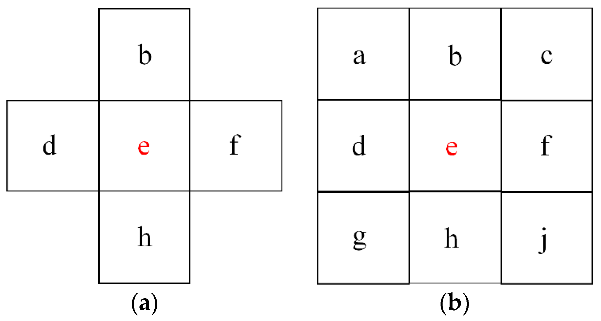
3.2. Cellular Automaton Model

The basic theory on the simulation of the grain coarsening comes from the decrease of the free energy of total computational domain. The change of the grain diameter (D) follows,
D t 2 D 0 2 = k t n
where k and n are constants related to material.
When the atoms jump from one side of the grain boundary to another, energy barrier (ΔGA) should be overcome. Considering the probability for the atom jumps across grain boundary, the probability functions can be found to be fit for both MC and CA [98],
P 1 = exp ( Δ G A / R T )
P 1 = exp ( ( Δ G A + Δ G ) / R T )
where ΔG is the free energy difference between grains.
CA method includes basic elements like cell, space, neighbor, and rules, as shown in Figure 4. Taking a two-dimensional case as an example, the discretization of two-dimensional space can lead to different grids with positive triangle, square and regular hexagon elements. As the form of expression is easier to implement, here square grid is adopted for the explanation of the simulation. The selection of the neighborhood types includes Neumann type, Moore type and alternating Moore type.
The CA method is discussed in a square grid. For the Moore neighbors type, the transformation rules are selected as follows [30],
  • If the state value of a cells e is the same as that of the eight adjacent neighbors, then the state value of the next step is constant;
  • (a) If any 3 of the cell b, d, f, and h is A States, the state of the cell e is converted to A at the next CAS;
    (b) If any 3 of the cell a, c, g, and j are A States, the state of the cell e is converted to A at the next CAS;
  • If the above conditions are not satisfied, each cell overcomes the energy barriers to change randomly into 8 adjacent cells, calculate the grain boundary energy change ΔE, the GBE for each site can be calculated by the Hamiltonian,
    E = J j m ( 1 δ s i s j ) .
The conversion probability is obtained by the following formula:
p = { 1 Δ E 0 exp ( Δ E k T ) Δ E > 0 .
For the Neumann neighbor type, the rules are as follows:
  • If the state value of a cells e is the same as that of the four adjacent neighbors, then the state value of the next step is constant;
  • If any 3 of the cell b, d, f, and h is A States, the state of the cell e is converted to A at the next CAS. It can be expressed as (1);
  • If the above conditions are not satisfied, each cell overcomes the energy barriers to change randomly into 4 adjacent cells, the rules of calculation are the same as formulas (3) and (4);
  • If the above conditions are not satisfied, randomly changes to the value of a neighbor cell.
Cellular automaton has been applied in laser AM for the simulations of dendrite formation in the solidification process [99,100,101,102].

3.3. Phase Field Model

Phase field (PF) method can be applied to the simulation of field dynamics simulation like impurity concentration, crystalline order, orientation and re- orientation, formation of dendrite. The spinodal decomposition and order-disorder kinetics can be also realized by the utilization of phase filed method [103]. The basic theory of phase field method is from the dissipative minimization of free energy. The microstructures are mathematically described as order parameters in the PF method. The order parameter can be treated as a continuous function. In a solidification case, its value can be variated from −1 representing liquid to +1 denoting completely solid state. It is unnecessary to track the movement of the boundaries of the phase changes. In MC and CA, the steps in simulation can only afterwards be related to the real time. However, in PF, the microstructure evolutions can be directly simulated towards the thermodynamic equilibrium with a real time solution. This is the advantage of PF but this point can lead to the obvious increase of computational time. As a computationally more demanding method, the domain for the simulation is generally small. So, the requirement of equilibrium on the computational domain and the full consideration of features on temperature changes should be designed in the extension of the thermodynamic energy for homogeneous system on interfaces. Free energy (FE), as the key for PF, can be expressed as [104,105],
F ( t ) = [ f 0 ( η 1 ( r , t ) , η 2 ( r , t ) , , η Q ( r , t ) ) + q = 1 Q k q 2 ( η q ( r , t ) ) 2 ] d r
where f0 is the local FE density. kq is coefficient of gradient energy related to GBE. ηq is continuous order parameter representing the crystallographic orientation of each grain. The local FE density can be written as
f 0 ( { η q ( r , t ) } ) = a 2 q = 1 Q η q 2 ( r , t ) + b 4 ( q = 1 Q η q 2 ( r , t ) ) 2 + ( c b 2 ) q = 1 Q s > q Q η q 2 ( r , t ) η s 2 ( r , t )
where a = b and c > a/2 being constants. When ηq = ±1 and ηs = 0 for all sq, f0 reaches 2Q minima.
It is generally to use Allen-Cahn equation for the solution of the order parameters ηq,
η q ( r , t ) t = L q ( T ) δ F ( t ) δ η q ( r , t ) ( q = 1 , 2 , , Q )
where Lq denotes GB mobility.
Then, the modified Arrhenius type equation can be utilized for the description on the temperature and thermal gradient contributions to the GE mobility,
L q ( T ) = L 0 ( T T a ) m exp ( Δ Q R g T )
where L0 and m are constants. ΔQ is the activate energy. Rg = 8.314 J/(mol·K) is gas constant.
Figure 5 reveals the dendrite grain structures coming from the PF model. In comparison with the experimental observations, the phase field model can be efficient to reveal the formation of dendrites in solidification in laser AM.
PF method is widely used in the simulation of microstructural evolutions in laser AM [107,108,109,110,111,112]. The integration of the phase field model into the crystal plasticity model [28,113,114,115] provides an efficient to correlate the microstructural changes with the mechanical properties and remains a hot topic for modelling and simulations in laser additive manufacturing.

3.4. Precipitate Evolution Model

The precipitation evolution model [116,117,118] can be used with combination of the LAM process model to calculate the evolutions of the second phase. Al-Mg-Si alloy is considered as an example of the material for LAM. The nucleation and the following coarsening of precipitates are the key process for the final formation of precipitates in precipitate hardening alloy like Al-Mg-Si. In the phase transformation process, the energy barriers include the interfacial energy and the elastic coherency strain energy. If the coherency strains are neglected on the nucleated sites of particles, the nucleation equation can be written as,
j = j 0 exp ( Δ G het R T ) exp ( Q d R T )
where j0(#/(m3·s)) is initial nucleation site number. Qd (J mol−1) is the activate energy of element diffusion. According to the classical nucleation theory, an appropriate expression for Δ G het is used for the critical energy barrier against heterogeneous nucleation,
Δ G het = ( A 0 ) 3 ( R T ) 2 [ ln ( C ¯ / C e ) ] 2
where C ¯ (wt.%) is the mean concentration of element in matrix in current stage. A0 (J mol−1) is the nucleation energy barrier. Ce (wt.%) is the solute concentration at the precipitate/matrix interface in equilibrium state,
C e = C s exp ( - Q s R T )
where Cs is pre-exponential term of Mg equilibrium concentration. Qs is the enthalpy of the solvus boundary.
The particle can be coarsening in a speed that can be calculated as,
v = d r d t = C ¯ C i C p C i D r
where Ci (wt.%) is the solute concentrations on the interface between particles and matrix. Cp represents the solute concentration of element inside the particles. Generally, Mg5Si3 can be considered to be the only stoichiometric composition of particles in simulation. D (m2·s−1) is a coefficient for diffusion of elements. r is the particle radius.
The solute at interface can be re-written with consideration of the Gibbs-Thomson equation,
C i = C e exp ( 2 γ V m r R T )
where γ (J·m−2) is interface energy between particle and matrix, and Vm (m3·mol−1) represents precipitation molar volume.
The precipitate stops to continuously grow in the case of equilibrium of C ¯ = C e . In this case, the critical radius in equilibrium state can be written as,
r = 2 γ V m R T ( ln ( C ¯ C e ) ) 1
In the following stage, the new nucleation is added in each time step as jt. The initial size of the newly generated particle should be larger than the critical value and it is recommended to be defined as 1.05 r*. The solute can exist in either the matrix or precipitates. The mass balance can be calculated,
f C p + ( 1 f ) C ¯ = C 0
where f can then be written as,
f = ( C 0 C ¯ ) / ( C p C ¯ )
Figure 6 reveals the discretization of the precipitates in the dimension of the radius. The precpitate can be assumed to be sphere-shaped and the volume can be calculated as,
f = i 4 3 π r i 3 N i
where Ni is particle number and ri is the corresponding radius.
From the above models, it can be seen that different models reveal different advantages and disadvantages in modelling and simulation of the microstructural evolutions in laser AM. MC and CA reveal high computational efficiency and PF shows its high ability revealing the physical nature of the process. For MC and CA, how to incorporate the physical nature in solidification and solid-state phase transformation is challenging. However, the problem related to robustness of the algorithm and the establishment of its model is still challenging for PF method, which can be the focus for the modelling and simulations of laser additive manufacturing.

4. Mechanical Properties

4.1. Physics Based Model

Physics-based models for the prediction of mechanical properties are established on the strengthening mechanism in materials science. This means that the model can be greatly different for different materials with different strengthening mechanisms in materials science. For precipitate strengthening materials like aluminum alloys, the physics-based model should mainly consider precipitate evolutions and correlate the precipitate evolutions with mechanical properties. For materials with grain and phase strengthening like titanium alloys, the mechanical response is established on the basis of dislocation density and its interactions with grain structures. Here we introduced the two models with the mentioned two strengthening effects.

4.1.1. Precipitate Evolution Based Model of Mechanical Property

The yield strength of material can be divided into three parts,
σ s = σ 0 + σ s s + σ p r e c i
where σss represents the contribution of solid solution and σp represents the contribution from the precipitates. σ0 represents the contribution from the pure grains. The contribution from the strenthening item from the dislocation density, σdd, should be included in this item, as well as the contribution from the frictional stress, σf.
σ d d = M α G b ρ
where M is the Taylor factor. α ranges from 0.2 to 1.5 [119]. G is the shear modulus. b is the Burgers vector and ρ is the dislocation density. The contribution from the dislocation density is close to 1 MPa and can be negligible. σ f is about 10 MPa for pure aluminum crystals.
The contribution from the solid solution [117] can be computed by,
σ s s = i = 1 3 k i C i 2 / 3
where ki represents the contributions from the different alloying element i. Ci is the corresponding solute concentration of element i. In current case, i = 1, 2 and 3 representing the contributions from the main elements like Mg, Si and Cu. The precipitate hardening is given by [117],
σ p = M F ¯ b L ¯
where L ¯ is mean distance between particles in the direction of the dislocation line. F ¯ represents the strength value to overcome obstacles,
F ¯ = i N i ( r ) F i ( r ) j N j ( r )
where Fi(r) is the discretized obstacle strength of i-th class. Depending on the particle sizes, the movement of the dislocation on the particles can be classified into two modes, shearing or bypassing particles. For precipitates with small sizes, the dislocation can cut off the precipitates by shearing. For precipitates with big sizes, the dislocation can bypass the precipitates to form dislocation loop. Both the cases can lead to the multiplication of dislocations and can be the basic strengthening mechanism for this kind of alloy. This also means that the critical value of rc should be defined to distinguish the two ways for the material strengthening. For the former case,
F i = 2 β G b 2 ( r i r c )
For the latter case,
F i = 2 β G b 2
where β is the dislocation tension [120,121].
σ p = M b r ¯ 2 β G b 2 1 / 2 3 f 2 π 1 / 2 F ¯ 3 / 2
When nano particles exist as strengthening items, the strengthening effect can be written as [122],
σ n = M b r ¯ n 2 β G b 2 1 / 2 3 f n 2 π 1 / 2 i N i F i i N i 3 / 2 .
where r ¯ n = ξ r p . ξ is defined to be the parameter related to the distribution of nanoparticles. rp is the radius of the nanoparticles. fn is the volume fraction of nanoparticles.

4.1.2. Dislocation Density Evolution Based Model of Mechanical Property

The flow stress is determined mainly by the interactions of immobile dislocation in long range σL and the dislocates interaction with short obstacles σs [123,124],
σ y = σ L + σ S
σ S = σ ath 1 k b T Δ f 0 G b 3 ln ε ˙ ref ε ¯ ˙ p 1 q 1 p
σ L = m α G b ρ i
where σ ath is the shear strength being dependent on temperature. ε ˙ ref is the reference strain rate [125]. ΔF = Δf0Gb is the activation energy overcoming the obstacles.
In the deformation of tension, the dislocation multiplication and the dislocation annihilation coexist, as below,
ρ ˙ i = ρ ˙ i + ρ ˙ i ( glide ) ρ ˙ i ( climb ) ρ ˙ i ( globularization )
where the dislocation annihilation is caused by glide, climbing and globularization.
The mobile dislocation density can be directly related to the plastic strain rate,
ρ ˙ i + = m b 1 Λ ε ¯ ˙ p
where Λ is the average moving distance of dislocation before it is annihilated or is transformed into immobile dislocation. It can be determined by [126],
1 Λ = 1 g + 1 s
where g and s are the sizes of grains and sub-grains.
The evolution of sub-grains can be described by [127],
1 s = ρ i K c
where Kc represents the parameter related to temperature.
The grain size is dependent on the time for heating,
g n g 0 n = K t
where g0 is the initial size of grain and K is the material parameter.
The dislocation annihilation is the main mechanism for dynamic recovery in deformation [128],
ρ ˙ i ( glide ) = Ω ρ i ε ¯ ˙ p
ρ ˙ i climb = 2 c r D app G b 3 k T ρ i 2 ρ eq 2
where Ω is a constant. cr is material parameter. Dapp is the diffusion rate.
Grain globularization observed in experiment in high temperature [129] can lead to the dislocation annihilation [130,131],
ρ ˙ i globularization = ψ X ˙ g ρ i ρ eq until ρ i ρ eq
ρ ˙ i globularization = 0 ,   when   ρ i < ρ cr
where X ˙ g is the globularization rate and ψ is the correction coefficient. And A the globularization rate can be divided into two parts [132],
X g = X d + 1 X d X s
where
X ˙ s = M g ˙ g
X ˙ d = B k p ε ¯ ˙ p ε ¯ p 1 k p e B ε ¯ p k p
where M, B and kp are material constants.

4.2. Crystal Plasticity Model

A simple decomposition of deformation gradient in large deformation can be found [133,134],
F = F e F p
F ˙ = L F
Assuming that the plastic state without consideration of the lattice rotation is the intermediate configuration (~ is added for the expressions in intermediate configuration), then [135,136],
L ˜ p = D ˜ p + W ˜ p = α γ ˙ α ( n ˜ α m ˜ α )
where n is the normal of the slipping plane and m is the slipping direction.
F ˜ ˙ p = L ˜ p F ˜ p
In the current configuration,
m ˜ α = F e m ˜ α 0
To keep the orthogonal of the slipping direction and slipping plate normal, i.e., n m = 0 , we have
n ˜ α = n ˜ α 0 F e 1
The slip rate on the αth slipping system can be represented as the power law function of the resolved shear stress and the slip resistance,
γ ˙ α = γ ˙ 0 α τ α g α 1 / m
where γ ˙ 0 α is the referenced shearing rate. m represents the sensitivity factor. The slipping resistance is divided into two items,
g α = τ 2 + τ obs 2
where [137]
τ = τ cr 1 k B T H 0 ln ε ˙ 0 γ ˙ 1 / q 1 / p
τ obs = A μ b β = 1 N S ρ β
where H0 is the activation enthalpy. τcr, ε0, p, q and A are constants, μ is the shear modulus. NS is the slipping system number, and ρβ is the dislocation density on β-th slipping system.
The use of finite elements in crystal plasticity model provides the possibility of the direct combination with the results of Monte Carlo model, phase field model, and cellular automaton. In Ref. [138], the lattices used in Monte Carlo simulation are directly projected to the finite elements in the crystal plasticity model for the studies on the influences of microstructures on mechanical behaviors in deformation of tension, as shown in Figure 7 and Figure 8. The crystal plasticity model can be extended into a three-dimensional case. Zhang et al. [133,134] proposed a three-dimensional case for the crystal plasticity model. The in-situ synchrotron X-ray diffraction was adopted to explain the mechanism for micromechanical behavior of AlSi3.5Mg2.5 (wt.%) alloy produced by PBF in two different states, as-built state, and direct-aged state.
The combination of crystal plasticity with the microstructural evolution model is one of the key problems connecting the microstructure and mechanical behavior in laser additive manufacturing, which can be important for the evaluation of additive manufacturing quality. This is the reason that this aspect has been becoming a hot topic in the simulation of the laser additive manufacturing in recent years. Among them, the combination of phase field model and the crystal plasticity model is very popular [28,114,139,140] due to the wide use of PF method in the simulation of the microstructural evolutions. Although key processes have been achieved, the integration of the microstructure and the mechanical response with consideration of the more details like defect formation, anisotropy and non-uniformity are strongly necessary. Moreover, the considerations of the formation of grain boundaries and the barrier energy and their relationship with dislocations in such a simulation is also a potential topic for further studies.
The physics-based model reveals the ability connecting the physical nature occurring in laser additive manufacturing including the changes of precipitates and the changes of the dislocations. However, the crystal plasticity model directly shows its ability connecting the grain morphologies with the mechanical responses of the grain clusters. In fact, the plasticity behavior in deformation is basically determined by the dislocation evolution and its interactions with the precipitate, grains, and defects. The bridging of the two models in modelling and simulation of mechanical properties is still challenging.
The changes of mechanical properties in laser additive manufacturing can be important factor determining the final dimensional accuracy incorporating the residual distortions [141] and can affect the further processing properties [142]. Residual stresses and distortions can be usually predicted by inherent strain method [143,144,145,146,147,148,149,150,151]. Although the method is valid and successful in many cases in current stage, the consideration of the mechanical property changes in the model using inherent strain method is still a challenge for the further development of models of residual states, which can be meaningful for the accurate controls of dimensional accuracy in laser additive manufacturing.
The temperature obtained from heat transfer analyses can be adopted for the further simulations on microstructures. The results of microstructural simulations can further affect the prediction of mechanical properties. How to integrate them together is still challenging. The process-structure-property relationship was well reviewed and summarized in Refs. [152,153,154,155,156,157]. The further combination of the reviewed methods to focus on the topic of process-structure-property relationship in laser additive manufacturing is hot topic and needs to be well studied in future.

5. Summaries and Perspectives

Process-structure-property relationship is the main topic for the modelling and simulation of laser additive manufacturing. The investigation on the process-structure-property relationship relies on the development of modelling and simulations in heat transfer, microstructural evolution, and the mechanical properties. The volumetric heat source model includes the Gaussian heat source model and the double ellipsoid heat source model. The combination of heat source models with powder features provides the possibility connecting the powders with the temperatures in laser additive manufacturing. The powder particles can be interacted with laser source and melt pool. It is the main factor in determining that additive manufacturing is different to the traditional welding process, in which it is complex to reveal all the effects of powders in the modelling and simulation. How to consider the powder effects in the modelling and simulation of additive manufacturing reflecting the physics of nature in additive manufacturing is still challenging. The microstructure evolutions can be simulated by Monte Carlo models, cellular automaton, and phase field models. The consideration of the powder and laser features can enhance the reliability of such models in comparison with experimental processes. The mechanical property is strongly affected by the material types. For MC and CA, how to incorporate the physical nature in solidification and solid-state phase transformation is challenging. However, the problem related to robustness of the algorithm and the establishment of its model is still challenging for PF method, which can be the focus for the modelling and simulations of laser additive manufacturing. The precipitate strengthening material can be predicted by the precipitate evolution-based model and the material related grains and phases can be predicted by the dislocation density based model. The further combination of the physics underlying the materials for strengthening effects with mechanical property should be developed in consideration of the different materials in laser additive manufacturing. The bridging of the two models in modelling and simulation of mechanical properties is still challenging.

Author Contributions

Z.Z., writing—original draft preparation, writing—review and editing, data curation; Y.W., investigation, formal analysis; P.G., investigation; T.W., investigation. All authors have read and agreed to the published version of the manuscript.

Funding

This research received no external funding.

Institutional Review Board Statement

Not applicable.

Informed Consent Statement

Not applicable.

Data Availability Statement

Not applicable.

Conflicts of Interest

The authors declare no conflict of interest.

References

  1. DebRoy, T.; Wei, H.L.; Zuback, J.S.; Mukherjee, T.; Elmer, J.W.; Milewski, J.O.; Beese, A.M.; Wilson-Heid, A.; De, A.; Zhang, W. Additive manufacturing of metallic components—Process, structure and properties. Prog. Mater. Sci. 2018, 92, 112–224. [Google Scholar] [CrossRef]
  2. Ngo, T.D.; Kashani, A.; Imbalzano, G.; Nguyen, K.T.Q.; Hui, D. Additive manufacturing (3D printing): A review of materials, methods, applications and challenges. Compos. Part B 2018, 143, 172–196. [Google Scholar] [CrossRef]
  3. Gu, D.D.; Meiners, W.; Wissenbach, K.; Poprawe, R. Laser additive manufacturing of metallic components: Materials, processes and mechanisms. Int. Mater. Rev. 2012, 57, 133–164. [Google Scholar] [CrossRef]
  4. Du Plessis, A.; Razavi, S.M.J.; Benedetti, M.; Murchio, S.; Leary, M.; Watson, M.; Bhate, D.; Berto, F. Properties and applications of additively manufactured metallic cellular materials: A review. Prog. Mater. Sci. 2022, 125, 100918. [Google Scholar] [CrossRef]
  5. Zhang, X.Q.; Zhang, K.Q.; Zhang, L.; Wang, W.Q.; Li, Y.; He, R.J. Additive manufacturing of cellular ceramic structures: From structure to structure-function integration. Mater. Des. 2022, 215, 110470. [Google Scholar] [CrossRef]
  6. Gu, D.D.; Shi, X.Y.; Poprawe, R.; Bourell, D.L.; Setchi, R.; Zhu, J.H. Material-structure-performance integrated laser-metal additive manufacturing. Science 2021, 372, abg1487. [Google Scholar] [CrossRef]
  7. Samodurova, M.; Logachev, I.; Shaburova, N.; Samoilova, O.; Radionova, L.; Zakirov, R.; Pashkeev, K.; Myasoedov, V.; Trofimov, E. A study of the structural characteristics of titanium alloy products manufactured using additive technologies by combining the selective laser melting and direct metal deposition methods. Materials 2019, 12, 3269. [Google Scholar] [CrossRef]
  8. Samodurova, M.; Shaburova, N.; Samoilova, O.; Radionova, L.; Zakirov, R.; Pashkeev, K.; Myasoedov, V.; Erdakov, I.; Trofimov, E. A study of characteristics of aluminum bronze coatings applied to steel using additive technologies. Materials 2020, 13, 461. [Google Scholar] [CrossRef]
  9. Erdakov, I.; Glebov, L.; Pashkeev, K.; Bykov, V.; Bryk, A.; Lezin, V.; Radionova, L. Effect of the Ti6Al4V alloy track trajectories on mechanical properties in direct metal deposition. Machines 2020, 8, 79. [Google Scholar] [CrossRef]
  10. Baitimerov, R.; Lykov, P.; Zherebtsov, D.; Radionova, L.; Shultc, A.; Prashanth, K.G. Influence of powder characteristics on processability of AlSi12 alloy fabricated by selective laser melting. Materials 2018, 11, 742. [Google Scholar] [CrossRef] [PubMed] [Green Version]
  11. Uriondo, A.; Esperon-Miguez, M.; Perinpanayagam, S. The present and future of additive manufacturing in the aerospace sector: A review of important aspects. Proc. Inst. Mech. Eng. Part G—J. Aerosp. Eng. 2015, 229, 2132–2147. [Google Scholar] [CrossRef]
  12. Fasel, U.; Keidel, D.; Baumann, L.; Cavolina, G.; Eichenhofer, M.; Ermanni, P. Composite additive manufacturing of morphing aerospace structures. Manuf. Lett. 2020, 23, 85–88. [Google Scholar] [CrossRef]
  13. Leal, R.; Barreiros, F.M.; Alves, L.; Romeiro, F.; Vasco, J.C.; Santos, M.; Marto, C. Additive manufacturing tooling for the automotive industry. Int. J. Adv. Manuf. Technol. 2017, 92, 1671–1676. [Google Scholar] [CrossRef]
  14. Ituarte, I.F.; Chekurov, S.; Tuomi, J.; Mascolo, J.E.; Zanella, A.; Springer, P.; Partanen, J. Digital manufacturing applicability of a laser sintered component for automotive industry: A case study. Rapid Prototyp. J. 2018, 24, 1203–1211. [Google Scholar] [CrossRef]
  15. Borrelli, A.; D’Errico, G.; Borrelli, C.; Citarella, R. Assessment of crash performance of an automotive component made through additive manufacturing. Appl. Sci. 2020, 10, 9106. [Google Scholar] [CrossRef]
  16. Segonds, F. Design by additive manufacturing: An application in aeronautics and defence. Virtual Phys. Prototyp. 2018, 13, 237–245. [Google Scholar] [CrossRef]
  17. Saccone, G.; Andreutti, G.; Lucariello, D.; Pirozzi, C.; Franchitti, S.; Borrelli, R.; Toscano, C.; Pascarella, C.; Caso, P.; Caiazzo, F. Performance improvement of piston engine in aeronautics by means of additive manufacturing technologies. J. Aerosp. Eng. 2021, 34, 04021065. [Google Scholar] [CrossRef]
  18. Zhang, Y.C.; Wang, Z.P.; Zhang, Y.C.; Gomes, S.; Bernard, A. Bio-inspired generative design for support structure generation and optimization in Additive Manufacturing (AM). CIRP Ann. -Manuf. Technol. 2020, 69, 117–120. [Google Scholar] [CrossRef]
  19. Basalah, A.; Esmaeili, S.; Toyserkani, E. Mechanical properties of additive-manufactured porous titanium bio-structures with oriented macro-scale channels. Int. J. Adv. Manuf. Technol. 2016, 84, 2239–2246. [Google Scholar] [CrossRef]
  20. Budholiya, S.; Bhat, A.; Raj, S.A.; Sultan, M.T.H.; Shah, A.U.M.; Basri, A.A. State of the art review about bio-inspired design and applications: An aerospace perspective. Appl. Sci. 2021, 11, 5054. [Google Scholar] [CrossRef]
  21. Tan, Z.J.; Zhang, Z. Band gap characteristics of friction stir additive manufactured phononic crystals. Phys. Scr. 2022, 97, 025702. [Google Scholar] [CrossRef]
  22. Guo, J.C.; Li, J.R.; Zhang, L.; Zhang, Z. Wide range of wave attenuation in beam-supported stepped hybrid phononic crystals. Wave Motion 2021, 108, 102827. [Google Scholar] [CrossRef]
  23. Hu, Y.; Guo, Z.P.; Ragonese, A.; Zhu, T.S.; Khuje, S.; Li, C.N.; Grossman, J.C.; Zhou, C.; Nouh, M.; Ren, S.Q. A 3D-printed molecular ferroelectric metamaterial. Proc. Natl. Acad. Sci. USA 2020, 117, 27204–27210. [Google Scholar] [CrossRef] [PubMed]
  24. Guo, J.C.; Zhang, Z. Mass inertia moment-based design of band gap characteristics in zigzag beam-supported stepped phononic crystals. Appl. Phys. A 2022, 128, 126. [Google Scholar] [CrossRef]
  25. Guo, J.C.; Li, J.R.; Zhang, Z. Interface design of low-frequency band gap characteristics in stepped hybrid phononic crystals. Appl. Acoust. 2021, 182, 108209. [Google Scholar] [CrossRef]
  26. Calleja-Ochoa, A.; Gonzalez-Barrio, H.; de Lacalle, N.L.; Martinez, S.; Albizuri, J.; Lamikiz, A. A new approach in the design of microstructured ultralight components to achieve maximum functional performance. Materials 2021, 14, 1588. [Google Scholar] [CrossRef]
  27. Perez-Ruiz, J.D.; Marin, F.; Martinez, S.; Lamikiz, A.; Urbikain, G.; de Lacalle, L.N.L. Stiffening near-net-shape functional parts of Inconel 718 LPBF considering material anisotropy and subsequent machining issues. Mech. Syst. Signal Process. 2022, 168, 108675. [Google Scholar] [CrossRef]
  28. Liu, P.W.; Wang, Z.; Xiao, Y.H.; Lebensohn, R.A.; Liu, Y.C.; Horstemeyer, M.F.; Cui, X.Y.; Chen, L. Integration of phase-field model and crystal plasticity for the prediction of process-structure-property relation of additively manufactured metallic materials. Int. J. Plast. 2020, 128, 102670. [Google Scholar] [CrossRef]
  29. Wang, X.; Liu, P.W.; Ji, Y.; Liu, Y.; Horstemeyer, M.H.; Chen, L. Investigation on microsegregation of IN718 alloy during additive manufacturing via integrated phase-field and finite-element modeling. J. Mater. Eng. Perform. 2019, 28, 657–665. [Google Scholar] [CrossRef]
  30. Zhang, Z.; Tan, Z.J.; Yao, X.X.; Hu, C.P.; Ge, P.; Wan, Z.Y.; Li, J.Y.; Wu, Q. Numerical methods for microstructural evolutions in laser additive manufacturing. Comput. Math. Appl. 2019, 78, 2296–2307. [Google Scholar] [CrossRef]
  31. McNamara, K.; Ji, Y.Z.; Lia, F.; Promoppatum, P.; Yao, S.C.; Zhou, H.L.; Wang, Y.; Chen, L.Q.; Martukanitz, R.P.P. Predicting phase transformation kinetics during metal additive manufacturing using non-isothermal Johnson-Mehl-Avrami models: Application to Inconel 718 and Ti-6Al-4V. Addit. Manuf. 2022, 49, 102478. [Google Scholar] [CrossRef]
  32. Kirka, M.M.; Nandwana, P.; Lee, Y.; Dehoff, R.R. Solidification and solid-state transformation sciences in metals additive manufacturing. Scr. Mater. 2017, 135, 130–134. [Google Scholar] [CrossRef]
  33. Zhang, Z.; Ge, P.; Li, J.Y.; Ren, D.X.; Wu, T. Monte Carlo simulations of solidification and solid-state phase transformation during directed energy deposition additive manufacturing. Prog. Addit. Manuf. 2022, 7, 671–682. [Google Scholar] [CrossRef]
  34. Papazoglou, E.L.; Karkalos, N.E.; Karmiris-Obratanski, P.; Markopoulos, A.P. On the modeling and simulation of SLM and SLS for metal and polymer powders: A review. Arch. Comput. Methods Eng. 2022, 29, 941–973. [Google Scholar] [CrossRef]
  35. Bayat, M.; Dong, W.; Thorborg, J. A review of multi-scale and multi-physics simulations of metal additive manufacturing processes with focus on modeling strategies. Addit. Manuf. 2021, 47, 102278. [Google Scholar] [CrossRef]
  36. Xie, R.S.; Chen, G.Q.; Zhao, Y.; Zhang, S.; Yan, W.T.; Lin, X.; Shi, Q.Y. In-situ observation and numerical simulation on the transient strain and distortion prediction during additive manufacturing. J. Manuf. Processes 2019, 38, 494–501. [Google Scholar] [CrossRef]
  37. Lian, Y.P.; Lin, S.; Yan, W.T.; Liu, W.K.; Wagner, G.J. A parallelized three-dimensional cellular automaton model for grain growth during additive manufacturing. Comput. Mech. 2018, 61, 543–558. [Google Scholar] [CrossRef]
  38. Yu, Y.F.; Yan, W.T.; Lin, F. Understanding the formation process of shrinkage pores with a 3D dendrite growth model: From casting to additive manufacturing. Comput. Mech. 2022, 69, 133–149. [Google Scholar] [CrossRef]
  39. Yan, Z.R.; Liu, W.W.; Tang, Z.J.; Liu, X.Y.; Zhang, N.; Li, M.Z.; Zhang, H.C. Review on thermal analysis in laser-based additive manufacturing. Opt. Laser Technol. 2018, 106, 427–441. [Google Scholar] [CrossRef]
  40. Tang, Z.J.; Liu, W.W.; Wang, Y.W.; Saleheen, K.M.; Liu, Z.C.; Peng, S.T.; Zhang, Z.; Zhang, H.C. A review on in situ monitoring technology for directed energy deposition of metals. Int. J. Adv. Manuf. Technol. 2020, 108, 3437–3463. [Google Scholar] [CrossRef]
  41. DebRoy, T.; Mukherjee, T.; Wei, H.L.; Elmer, J.W.; Milewski, J.O. Metallurgy, mechanistic models and machine learning in metal printing. Nat. Rev. Mater. 2020, 6, 48–68. [Google Scholar] [CrossRef]
  42. Joe, J.; Barber, J.R.; Raeymaekers, B. A general load-displacement relationship between random rough surfaces in elastic, non-adhesive contact, with application in metal additive manufacturing. Tribol. Lett. 2022, 70, 77. [Google Scholar] [CrossRef]
  43. Li, J.Y.; Yao, X.X.; Wang, Y.F.; Gao, X.; Zhang, Z. The simulation of post-heat treatment in selective laser melting additive manufacturing. Integr. Mater. Manuf. Innov. 2021, 10, 413–428. [Google Scholar] [CrossRef]
  44. Siao, Y.H.; Wen, C.D. Examination of molten pool with Marangoni flow and evaporation effect by simulation and experiment in selective laser melting. Int. Commun. Heat Mass Transf. 2021, 125, 105325. [Google Scholar] [CrossRef]
  45. Taylor, S.; Wright, J.B.; Forrest, E.C.; Jared, B.; Koepke, J.; Beaman, J. Investigating relationship between surface topography and emissivity of metallic additively manufactured parts. Int. Commun. Heat Mass Transf. 2020, 115, 104614. [Google Scholar] [CrossRef]
  46. Hagqvist, P.; Sikstrom, F.; Christiansson, A.K. Emissivity estimation for high temperature radiation pyrometry on Ti-6Al-4V. Measurement 2013, 46, 871–880. [Google Scholar] [CrossRef]
  47. Qu, D.X.; Berry, J.; Calta, N.P.; Crumb, M.F.; Guss, G.; Matthews, M.J. Temperature measurement of laser-irradiated metals using hyperspectral imaging. Phys. Rev. Appl. 2020, 14, 014031. [Google Scholar] [CrossRef]
  48. Ren, C.G.; Lo, Y.L.; Tran, H.C.; Lee, M.H. Emissivity calibration method for pyrometer measurement of melting pool temperature in selective laser melting of stainless steel 316L. Int. J. Adv. Manuf. Technol. 2019, 105, 637–649. [Google Scholar] [CrossRef]
  49. Goldak, J.; Chakravarti, A.; Bibby, M. A new finite-element model for welding heat-sources. Metall. Trans. B 1984, 15, 299–305. [Google Scholar] [CrossRef]
  50. Heinze, C.; Schwenk, C.; Rethmeier, M. Effect of heat source configuration on the result quality of numerical calculation of welding-induced distortion. Simul. Model. Pract. Theory 2012, 20, 112–123. [Google Scholar] [CrossRef]
  51. Zhang, Z.; Ge, P.; Zhao, G.Z. Numerical studies of post weld heat treatment on residual stresses in welded impeller. Int. J. Press. Vessel Pip. 2017, 153, 1–14. [Google Scholar] [CrossRef]
  52. Zhou, X.F.; Cao, X.B.; Zhang, F.; Duan, J.A. Numerical and experimental investigation of thermal stress distribution in laser lap welding of Ti6Al4V and 2024 alloy plates. Int. J. Adv. Manuf. Technol. 2022, 118, 1427–1440. [Google Scholar] [CrossRef]
  53. Sripriyan, K.; Ramu, M.; Thyla, P.R.; Anantharuban, K. Weld bead characterization of flat wire electrode in gmaw process part II: A numerical study. J. Mech. Sci. Technol. 2021, 35, 2615–2622. [Google Scholar] [CrossRef]
  54. Liu, P.W.; Cui, X.Y.; Deng, J.S.; Li, S.; Li, Z.C.; Chen, L. Investigation of thermal responses during metallic additive manufacturing using a “Tri-Prism” finite element method. Int. J. Therm. Sci. 2019, 136, 217–229. [Google Scholar] [CrossRef]
  55. Giarollo, D.F.; Mazzaferro, C.C.P.; Mazzaferro, J.A.E. Comparison between two heat source models for wire-arc additive manufacturing using GMAW process. J. Braz. Soc. Mech. Sci. Eng. 2022, 44, 7. [Google Scholar] [CrossRef]
  56. Jing, H.; Ge, P.; Zhang, Z.; Chen, J.Q.; Liu, Z.M.; Liu, W.W. Numerical studies of the effects of the substrate structure on the residual stress in laser directed energy additive manufacturing of thin-walled products. Metals 2022, 12, 462. [Google Scholar] [CrossRef]
  57. Anca, A.; Fachinotti, V.D.; Escobar-Palafox, G.; Cardona, A. Computational modelling of shaped metal deposition. Int. J. Numer. Methods Eng. 2011, 85, 84–106. [Google Scholar] [CrossRef]
  58. Mi, G.Y.; Wei, Y.H.; Zhan, X.H.; Gu, C.; Yu, F.Y. A coupled thermal and metallurgical model for welding simulation of Ti–6Al–4V alloy. J. Mater. Process. Technol. 2014, 214, 2434–2443. [Google Scholar] [CrossRef]
  59. Gao, X.; Yao, X.X.; Niu, F.Y.; Zhang, Z. The influence of nozzle geometry on powder flow behaviors in directed energy deposition additive manufacturing. Adv. Powder Technol. 2022, 33, 103487. [Google Scholar] [CrossRef]
  60. Yao, X.X.; Li, J.Y.; Wang, Y.F.; Gao, X.; Li, T.; Zhang, Z. Experimental and numerical studies of nozzle effect on powder flow behaviors in directed energy deposition additive manufacturing. Int. J. Mech. Sci. 2021, 210, 106740. [Google Scholar] [CrossRef]
  61. Barros, F.M.F.; Duc, E.; Nedelec, J.M.; Falk, V.; Marchal, P. Characterization of flow properties of gas-atomized powder alloys used for additive manufacturing: Comparison between traditional methods and vibrated rheology. Part. Part. Syst. Charact. 2022, 153, 2100151. [Google Scholar] [CrossRef]
  62. Jiang, S.; Zheng, B.L.; Schoenung, J.M. Directed energy deposition of metal matrix composites: Computational and experimental comparison of powder particle flow behavior. J. Mater. Res. Technol. 2021, 16, 516–529. [Google Scholar] [CrossRef]
  63. Kroeger, J.; Poirie, T.; Moghimian, P.; Marion, F.; Larouche, F. Flow rate ranges for spherical metallic powders for additive manufacturing. Prog. Addit. Manuf. 2022, 7, 411–418. [Google Scholar] [CrossRef]
  64. Iams, A.D.; Gao, M.Z.; Shetty, A.; Palmer, T.A. Influence of particle size on powder rheology and effects on mass flow during directed energy deposition additive manufacturing. Powder Technol. 2022, 396, 316–326. [Google Scholar] [CrossRef]
  65. Zhang, Z.; Ge, P.; Li, T.; Lindgren, L.E.; Liu, W.W.; Zhao, G.Z.; Guo, X. Electromagnetic wave-based analysis of laser–particle interactions in directed energy deposition additive manufacturing. Addit. Manuf. 2020, 34, 101284. [Google Scholar] [CrossRef]
  66. Manvatkar, V.; De, A.; DebRoy, T. Heat transfer and material flow during laser assisted multi-layer additive manufacturing. J. Appl. Phys. 2014, 116, 124905. [Google Scholar] [CrossRef]
  67. Ge, P.; Zhang, Z.; Tan, Z.J.; Hu, C.P.; Zhao, G.Z.; Guo, X. An integrated modeling of process-structure-property relationship in laser additive manufacturing of duplex titanium alloy. Int. J. Therm. Sci. 2019, 140, 329–343. [Google Scholar] [CrossRef]
  68. Yan, W.; Ge, W.; Qian, Y.; Lin, S.; Zhou, B.; Liu, W.K.; Lin, F.; Wagner, G.J. Multi-physics modeling of single/multiple-track defect mechanisms in electron beam selective melting. Acta Mater. 2017, 134, 324–333. [Google Scholar] [CrossRef]
  69. Yang, M.; Wang, L.; Yan, W.T. Phase-field modeling of grain evolution in additive manufacturing with addition of reinforcing particles. Addit. Manuf. 2021, 47, 102286. [Google Scholar] [CrossRef]
  70. Tyagi, S.A.; Manjaiah, M. Laser additive manufacturing of titanium-based functionally graded materials: A review. J. Mater. Eng. Perform. 2022, 31, 6131–6148. [Google Scholar] [CrossRef]
  71. Schoinochoritis, B.; Chantzis, D.; Salonitis, K. Simulation of metallic powder bed additive manufacturing processes with the finite element method: A critical review. Proc. Inst. Mech. Eng. Part B -J. Eng. Manuf. 2017, 231, 96–117. [Google Scholar] [CrossRef]
  72. Guan, X.Y.; Zhao, Y.F. Modeling of the laser powder-based directed energy deposition process for additive manufacturing: A review. Int. J. Adv. Manuf. Technol. 2020, 107, 1959–1982. [Google Scholar] [CrossRef]
  73. Al Hamahmy, M.I.; Deiab, I. Review and analysis of heat source models for additive manufacturing. Int. J. Adv. Manuf. Technol. 2020, 106, 1223–1238. [Google Scholar] [CrossRef]
  74. Liu, C.M.; Gao, H.B.; Li, L.Y.; Wang, J.D.; Guo, C.H.; Jiang, F.C. A review on metal additive manufacturing: Modeling and application of numerical simulation for heat and mass transfer and microstructure evolution. China Foundry 2021, 18, 317–334. [Google Scholar] [CrossRef]
  75. Kundakcioglu, E.; Lazoglu, I.; Rawal, S. Transient thermal modeling of laser-based additive manufacturing for 3D freeform structures. Int. J. Adv. Manuf. Technol. 2016, 85, 493–501. [Google Scholar] [CrossRef]
  76. Yan, Z.; Song, L.J.; Liu, W.Y.; Zou, X.; Zhou, Z.P. Numerical analysis of thermal stress evolution of pulsed-wave laser direct energy deposition. Int. J. Adv. Manuf. Technol. 2021, 115, 1399–1410. [Google Scholar] [CrossRef]
  77. Tang, Y.J.; Zhang, Y.Z.; Liu, Y.T. Numerical and experimental investigation of laser additive manufactured Ti2AlNb-based alloy. J. Alloy. Compd. 2017, 727, 196–204. [Google Scholar] [CrossRef]
  78. Peyre, P.; Dal, M.; Pouzet, S.; Castelnau, O. Simplified numerical model for the laser metal deposition additive manufacturing process. J. Laser Appl. 2017, 29, 022304. [Google Scholar] [CrossRef]
  79. Zhang, Z.; Ge, P.; Li, J.Y.; Wang, Y.F.; Gao, X.; Yao, X.X. Laser-particle interaction-based analysis of powder particle effects on temperatures and distortions in directed energy deposition additive manufacturing. J. Therm. Stresses 2021, 44, 1068–1095. [Google Scholar] [CrossRef]
  80. Panda, B.K.; Sahoo, S. Thermo-mechanical modeling and validation of stress field during laser powder bed fusion of AlSi10Mg built part. Results Phys. 2019, 12, 1372–1381. [Google Scholar] [CrossRef]
  81. Zhao, X.R.; Iyer, A.; Promoppatum, P.; Yao, S.C. Numerical modeling of the thermal behavior and residual stress in the direct metal laser sintering process of titanium alloy products. Addit. Manuf. 2017, 14, 126–136. [Google Scholar] [CrossRef]
  82. Kundakcioglu, E.; Lazoglu, I.; Poyraz, O.; Yasa, E.; Cizicioglu, N. Thermal and molten pool model in selective laser melting process of Inconel 625. Int. J. Adv. Manuf. Technol. 2018, 95, 3977–3984. [Google Scholar] [CrossRef]
  83. Roberts, I.A.; Wang, C.J.; Esterlein, R.; Stanford, M.; Mynors, D.J. A three-dimensional finite element analysis of the temperature field during laser melting of metal powders in additive layer manufacturing. Int. J. Mach. Tools Manuf. 2009, 49, 916–923. [Google Scholar] [CrossRef]
  84. Shahabad, S.I.; Zhang, Z.D.; Keshavarzkermani, A.; Ali, U.; Mahmoodkhani, Y.; Esmaeilizadeh, R.; Bonakdar, A.; Toyserkani, E. Heat source model calibration for thermal analysis of laser powder-bed fusion. Int. J. Adv. Manuf. Technol. 2020, 106, 3367–3379. [Google Scholar] [CrossRef]
  85. Wu, Y.J.; Sun, K.; Yu, S.F.; Zuo, L. Modeling the selective laser melting-based additive manufacturing of thermoelectric powders. Addit. Manuf. 2021, 37, 101666. [Google Scholar] [CrossRef]
  86. Novotny, L.; Beres, M.; de Abreu, H.F.G.; Zajac, J.; Bleck, W. Thermal analysis and phase transformation behaviour during additive manufacturing of Ti-6Al-4V alloy. Mater. Sci. Technol. 2019, 35, 846–855. [Google Scholar] [CrossRef]
  87. Samantaray, M.; Sahoo, S.; Thatoi, D. Modeling of thermal and solidification behavior during laser additive manufacturing of AlSi10Mg alloy powders and its experimental validation. J. Laser Appl. 2019, 31, 032019. [Google Scholar] [CrossRef]
  88. Romano, J.; Ladani, L.; Sadowski, M. Thermal modeling of laser based additive manufacturing processes within common materials. Procedia Manuf. 2015, 5, 238–250. [Google Scholar] [CrossRef]
  89. Zhang, Z.D.; Huang, Y.; Kasinathan, A.R.; Shahabad, S.I.; Ali, U.; Mahmoodkhani, Y.; Toyserkani, E. 3-Dimensional heat transfer modeling for laser powder-bed fusion additive manufacturing with volumetric heat sources based on varied thermal conductivity and absorptivity. Opt. Laser Technol. 2019, 109, 297–312. [Google Scholar] [CrossRef]
  90. Yao, X.X.; Zhang, Z. Laser-particle interaction-based heat source model of laser powder bed fusion additive manufacturing. Opt. Laser Technol. 2022, 155, 108402. [Google Scholar] [CrossRef]
  91. Zhang, Z.; Wu, Q.; Grujicic, M.; Wan, Z.Y. Monte Carlo simulation of grain growth and welding zones in friction stir welding of AA6082-T6. J. Mater. Sci. 2016, 51, 1882–1895. [Google Scholar] [CrossRef]
  92. Grujicic, M.; Ramaswami, S.; Snipes, J.S.; Avuthu, V.; Galgalikar, R.; Zhang, Z. Prediction of the grain-microstructure evolution within a Friction Stir Welding (FSW) joint via the use of the Monte Carlo simulation method. J. Mater. Eng. Perform. 2015, 24, 3471–3486. [Google Scholar] [CrossRef]
  93. Zhang, Z.; Hu, C.P. 3D Monte Carlo simulation of grain growth in friction stir welding. J. Mech. Sci. Technol. 2018, 32, 1287–1296. [Google Scholar] [CrossRef]
  94. Xiao, Y.H.; Wan, Z.X.; Liu, P.W.; Wang, Z.; Li, J.J.; Chen, L. Quantitative simulations of grain nucleation and growth at additively manufactured bimetallic interfaces of SS316L and IN625. J. Mater. Process. Technol. 2022, 302, 117506. [Google Scholar] [CrossRef]
  95. Rodgers, T.M.; Madison, J.D.; Tikare, V. Simulation of metal additive manufacturing microstructures using kinetic Monte Carlo. Comput. Mater. Sci. 2017, 135, 78–89. [Google Scholar] [CrossRef]
  96. Rodgers, T.M.; Moser, D.; Abdeljawad, F.; Jackson, O.D.U.; Carroll, J.D.; Jared, B.H.; Bolintineanu, D.S.; Mitchell, J.A.; Madison, J.D. Simulation of powder bed metal additive manufacturing microstructures with coupled finite difference-Monte Carlo method. Addit. Manuf. 2021, 41, 101953. [Google Scholar] [CrossRef]
  97. Zhou, X.W.; Karnesky, R.A.; Yang, N.; Yee, J.K. Kinetic Monte Carlo simulations of structural evolution during anneal of additively manufactured materials. Comput. Mater. Sci. 2020, 179, 109605. [Google Scholar] [CrossRef]
  98. Zinoviev, A.; Zinovieva, O.; PLoshikhin, V.; Romanova, V.; Balokhonov, R. Evolution of grain structure during laser additive manufacturing: Simulation by a cellular automata method. Mater. Des. 2016, 106, 321–329. [Google Scholar] [CrossRef]
  99. Teferra, K.; Rowenhorst, D.J. Optimizing the cellular automata finite element model for additive manufacturing to simulate large microstructures. Acta Mater. 2021, 213, 116930. [Google Scholar] [CrossRef]
  100. Sun, W.Z.; Shan, F.H.; Zong, N.F.; Dong, H.B.; Jing, T. Simulation of solidified beta grain for Ti-6Al-4V during wire laser additive manufacturing by three-dimensional cellular automaton method. Model. Simul. Mater. Sci. Eng. 2021, 29, 065006. [Google Scholar] [CrossRef]
  101. Bailey, N.S.; Shin, Y.C. Multi-track, multi-layer dendrite growth and solid phase transformation analysis during additive manufacturing of H13 tool steel using a combined hybrid cellular automata/phase field, solid-state phase prediction models. Int. J. Adv. Manuf. Technol. 2022, 120, 2089–2108. [Google Scholar] [CrossRef]
  102. Wu, L.M.; Zhang, J. Phase field simulation of dendritic solidification of Ti-6Al-4V during additive manufacturing process. JOM 2018, 70, 2392–2399. [Google Scholar] [CrossRef]
  103. Rappaz, M.; Gandin, C.A. Probabilistic modeling of microstructure formation in solidification processes. Acta Metall. Mater. 1993, 41, 345–360. [Google Scholar] [CrossRef]
  104. Provatas, N.; Dantzig, J.A.; Athreya, B. Using the phase-field crystal method in the multi-scale modeling of microstructure evolution. JOM 2007, 59, 83–90. [Google Scholar] [CrossRef]
  105. Yao, X.X.; Li, J.Y.; Wang, Y.F.; Gao, X.; Zhang, Z. Numerical simulation of powder effect on solidification in directed energy deposition additive manufacturing. Trans. Nonferrous Soc. China 2021, 31, 2871–2884. [Google Scholar] [CrossRef]
  106. Yao, X.X.; Ge, P.; Li, J.Y.; Wang, Y.F.; Li, T.; Liu, W.W.; Zhang, Z. Controlling the solidification process parameters of direct energy deposition additive manufacturing considering laser and powder properties. Comput. Mater. Sci. 2020, 182, 109788. [Google Scholar] [CrossRef]
  107. Zhang, Z.; Yao, X.X.; Ge, P. Phase-field-model-based analysis of the effects of powder particle on porosities and densities in selective laser sintering additive manufacturing. Int. J. Mech. Sci. 2020, 166, 105230. [Google Scholar] [CrossRef]
  108. Li, L.; Li, J.Q.; Fan, T.H. Phase-field modeling of wetting and balling dynamics in powder bed fusion process. Phys. Fluids 2021, 33, 042116. [Google Scholar] [CrossRef]
  109. Boussinot, G.; Doring, M.; Hemes, S.; Stryzhyboroda, O.; Apel, M.; Schmidt, M. Laser powder bed fusion of eutectic Al-Ni alloys: Experimental and phase-field studies. Mater. Des. 2021, 198, 109299. [Google Scholar] [CrossRef]
  110. Keller, T.; Lindwall, G.; Ghosh, S.; Ma, L.; Lane, B.M.; Zhang, F.; Kattner, U.R.; Lass, E.A.; Heigel, J.C.; Idell, Y.; et al. Application of finite element, phase-field, and CALPHAD-based methods to additive manufacturing of Ni-based superalloys. Acta Mater. 2017, 139, 244–253. [Google Scholar] [CrossRef]
  111. Sahoo, S.; Chou, K. Phase-field simulation of microstructure evolution of Ti-6Al-4V in electron beam additive manufacturing process. Addit. Manuf. 2016, 9, 14–24. [Google Scholar] [CrossRef]
  112. Lu, L.X.; Sridhar, N.; Zhang, Y.W. Phase field simulation of powder bed-based additive manufacturing. Acta Mater. 2018, 144, 801–809. [Google Scholar] [CrossRef]
  113. Li, Z.; Wang, T.; Chu, D.Y.; Liu, Z.; Cui, Y. A coupled crystal-plasticity and phase-field model for understanding fracture behaviors of single crystal tungsten. Int. J. Plast. 2022, 157, 103375. [Google Scholar] [CrossRef]
  114. Agius, D.; O’Toole, P.; Wallbrink, C.; Sterjovski, Z.; Wang, C.H.; Schaffer, G.B. Integrating phase field and crystal plasticity finite element models for simulations of titanium alloy Ti-5553. J. Phys.-Mater. 2021, 4, 044014. [Google Scholar] [CrossRef]
  115. Wu, R.H.; Zhang, Y.F. Phase-field, dislocation based plasticity and damage coupled model: Modelling and application to single crystal superalloys. Int. J. Plast. 2022, 157, 103376. [Google Scholar] [CrossRef]
  116. Carron, D.; Bastid, P.; Yin, Y.; Faulkner, R.G. Modelling of precipitation during friction stir welding of anAl-Mg-Si alloy. Tech. Mech. 2010, 30, 29–44. [Google Scholar]
  117. Myhr, O.R.; Grong, Ø.; Andersen, S.J. Modelling of the age hardening behaviour of Al–Mg–Si alloys. Acta Mater. 2001, 49, 65–75. [Google Scholar] [CrossRef]
  118. Myhr, O.R.; Grong, Ø. Modelling of non-isothermal transformations in alloys containing a particle distribution. Acta Mater. 2000, 48, 1605–1615. [Google Scholar] [CrossRef]
  119. Simar, A.; Bréchet, Y.; de Meester, B.; Denquin, A.; Gallais, C.; Pardoen, T. Integrated modeling of friction stir welding of 6xxx series Al alloys: Process, microstructure and properties. Prog. Mater. Sci. 2012, 57, 95–183. [Google Scholar] [CrossRef]
  120. Zhang, Z.; Tan, Z.J.; Li, J.Y.; Zu, Y.F.; Sha, J.J. Integrated modeling of process-microstructure-property relations in friction stir additive manufacturing. Acta Metall. Sin. 2020, 33, 75–87. [Google Scholar] [CrossRef]
  121. Zhang, Z.; Tan, Z.J.; Li, J.Y.; Zu, Y.F.; Liu, W.W.; Sha, J.J. Experimental and numerical studies of re-stirring and re-heating effects on mechanical properties in friction stir additive manufacturing. Int. J. Adv. Manuf. Technol. 2019, 104, 767–784. [Google Scholar] [CrossRef]
  122. Tan, Z.J.; Li, J.Y.; Zhang, Z. Experimental and numerical studies on fabrication of nanoparticle reinforced aluminum matrix composites by friction stir additive manufacturing. J. Mater. Res. Technol. 2021, 12, 1898–1912. [Google Scholar] [CrossRef]
  123. Bergstrom, Y. A dislocation model for the stress-strain behaviour of polycrystalline alpha-Fe with special emphasis on the variation of the densities of mobile and immobile dislocations. Mater. Sci. Eng. 1970, 5, 193–200. [Google Scholar] [CrossRef]
  124. Kocks, U.F. Laws for work-hardening and low-temperature creep. J. Eng. Mater. Technol. 1976, 98, 76–85. [Google Scholar] [CrossRef]
  125. Babu, B.; Lindgren, L.E. Dislocation density based model for plastic deformation and globularization of Ti-6Al-4V. Int. J. Plast. 2013, 50, 94–108. [Google Scholar] [CrossRef]
  126. Malmelov, A.; Fisk, M.; Lundback, A.; Lindgren, L.E. Mechanism based flow stress model for alloy 625 and alloy 718. Materials 2020, 13, 5620. [Google Scholar] [CrossRef]
  127. Holt, D.L. Dislocation cell formation in metals. J. Appl. Phys. 1970, 41, 3197–3201. [Google Scholar] [CrossRef]
  128. Lindgren, L.E.; Domkin, K.; Hansson, S. Dislocations, vacancies and solute diffusion in physical based plasticity model for AISI 316L. Mech. Mater. 2008, 40, 907–919. [Google Scholar] [CrossRef]
  129. Sargent, G.A.; Zane, A.P.; Fagin, P.N.; Ghosh, A.K.; Semiatin, S.L. Low-temperature coarsening and plastic flow behavior of an alpha/beta titanium billet material with an ultrafine microstructure. Metall. Mater. Trans. A 2008, 39, 2949–2964. [Google Scholar] [CrossRef]
  130. Dalai, B.; Moretti, M.A.; Akerstrom, P.; Arvieu, C.; Jacquin, D.; Lindgren, L.E. Mechanical behavior and microstructure evolution during deformation of AA7075-T651. Mater. Sci. Eng. A 2021, 822, 141615. [Google Scholar] [CrossRef]
  131. Pietrzyk, M. Identification of parameters in the history dependent constitutive model for steels. CIRP Ann.-Manuf. Technol. 2001, 50, 161–164. [Google Scholar] [CrossRef]
  132. Babu, B.; Lundback, A.; Lindgren, L.E. Simulation of Ti-6Al-4V additive manufacturing using coupled physically based flow stress and metallurgical model. Materials 2019, 12, 3844. [Google Scholar] [CrossRef] [PubMed]
  133. Zhang, X.X.; Lutz, A.; Andra, H.; Lahres, M.; Sittig, D.; Maawad, E.; Gan, W.M.; Knoop, D. An additively manufactured and direct-aged AlSi3.5Mg2.5 alloy with superior strength and ductility: Micromechanical mechanisms. Int. J. Plast. 2021, 146, 103083. [Google Scholar] [CrossRef]
  134. Zhang, X.X.; Andrä, H. Crystal plasticity simulation of the macroscale and microscale stress–strain relations of additively manufactured AlSi10Mg alloy. Comput. Mater. Sci. 2021, 200, 110832. [Google Scholar] [CrossRef]
  135. Peirce, D.; Asaro, R.J.; Needleman, A. An analysis of nonuniform and localized deformation in ductile single crystals. Acta Metall. 1982, 30, 1087–1119. [Google Scholar] [CrossRef]
  136. Lim, H.; Abdeljawad, F.; Owen, S.J.; Hanks, B.W.; Foulk, J.W.; Battaile, C.C. Incorporating physically-based microstructures in materials modeling: Bridging phase field and crystal plasticity frameworks. Model. Simul. Mater. Sci. Eng. 2016, 24, 045016. [Google Scholar] [CrossRef]
  137. Lim, H.; Hale, L.M.; Zimmerman, Z.A.; Battaile, C.C.; Weinberger, C.R. A multi-scale model of dislocation plasticity in α-Fe: Incorporating temperature, strain rate and non-Schmid effects. Int. J. Plast. 2015, 73, 100–118. [Google Scholar] [CrossRef]
  138. Yuan, H.L.; Tan, Z.J.; Zhang, Z. Numerical simulation of friction stir welding based on microstructure mechanical behavior integration calculation. J. Plast. Eng. 2020, 27, 182–191. (In Chinese) [Google Scholar]
  139. Pinomaa, T.; Yashchuk, I.; Lindroos, M.; Andersson, T.; Provatas, N.; Laukkanen, A. Process-structure-properties-performance modeling for selective laser melting. Metals 2019, 9, 1138. [Google Scholar] [CrossRef]
  140. Zhang, J.H.; Li, X.X.; Xu, D.S.; Yang, R. Recent progress in the simulation of microstructure evolution in titanium alloys. Prog. Nat. Sci. -Mater. Int. 2019, 29, 295–304. [Google Scholar] [CrossRef]
  141. Casuso, M.; Veiga, F.; Suarez, A.; Bhujangrao, T.; Aldalur, E.; Artaza, T.; Amondarain, J.; Lamikiz, A. Model for the Prediction of Deformations in the Manufacture of Thin-Walled Parts by Wire Arc Additive Manufacturing Technology. Metals 2021, 11, 678. [Google Scholar] [CrossRef]
  142. Perez-Ruiz, J.D.; de Lacalle, L.N.L.; Urbikain, G.; Pereira, O.; Martinez, S.; Bris, J. On the relationship between cutting forces and anisotropy features in the milling of LPBF Inconel 718 for near net shape parts. Int. J. Mach. Tools Manuf. 2021, 170, 103801. [Google Scholar] [CrossRef]
  143. Xu, S.Z.; Liu, J.K.; Ma, Y.S. Residual stress constrained self-support topology optimization for metal additive manufacturing. Comput. Methods Appl. Mech. Eng. 2022, 389, 114380. [Google Scholar] [CrossRef]
  144. Setien, I.; Chiumenti, M.; van der Veen, S.; San Sebastian, M.; Garciandia, F.; Echeverria, A. Empirical methodology to determine inherent strains in additive manufacturing. Comput. Math. Appl. 2019, 78, 2282–2295. [Google Scholar] [CrossRef]
  145. Liang, X.; Cheng, L.; Chen, Q.; Yang, Q.C.; To, A.C. A modified method for estimating inherent strains from detailed process simulation for fast residual distortion prediction of single-walled structures fabricated by directed energy deposition. Addit. Manuf. 2018, 23, 471–486. [Google Scholar] [CrossRef]
  146. Wang, Y.F.; Li, Q.; Qian, L.Y.; Yang, Y.B. A modified inherent strain model with consideration of the variance of mechanical properties in metal additive manufacturing. J. Manuf. Processes 2021, 72, 115–125. [Google Scholar] [CrossRef]
  147. Lyu, D.D.; Hu, W.; Ren, B.; Pan, X.F.; Wu, C.T. Numerical Prediction of Residual Deformation and Failure for Powder Bed Fusion Additive Manufacturing of Metal Parts. J. Mech. 2020, 36, 623–636. [Google Scholar] [CrossRef]
  148. Bugatti, M.; Semeraro, Q. Limitations of the inherent strain method in simulating powder bed fusion processes. Addit. Manuf. 2018, 23, 329–346. [Google Scholar] [CrossRef]
  149. Chen, Y.; Liu, Y.; Chen, H.; Wu, Y.; Chen, J.Q.; Xiong, J.; Ren, L.S.; Qian, J. Multi-scale residual stress prediction for selective laser melting of high strength steel considering solid-state phase transformation. Opt. Laser Technol. 2022, 146, 107578. [Google Scholar] [CrossRef]
  150. Zhang, Z.; Ge, P.; Yao, X.X.; Li, T.; Liu, W.W. Numerical studies of residual states and scaling effects in laser-directed energy deposition additive manufacturing. Int. J. Adv. Manuf. Technol. 2020, 108, 1233–1247. [Google Scholar] [CrossRef]
  151. Wang, Y.F.; Guo, J.C.; Zhang, Z. The deformation induced tunable topology in controlling of band gap characteristics for stepped phononic crystals. Solid State Commun. 2022, 351, 114809. [Google Scholar] [CrossRef]
  152. Hashemi, S.M.; Parvizi, S.; Baghbanijavid, H.; Tan, A.T.L.; Nematollahi, M.; Ramazani, A.; Fang, N.I.X.; Elahinia, M. Computational modelling of process-structure-property-performance relationships in metal additive manufacturing: A review. Int. Mater. Rev. 2022, 67, 1–46. [Google Scholar] [CrossRef]
  153. Goh, G.D.; Yap, Y.L.; Tan, H.K.J.; Sing, S.L.; Goh, G.L.; Yeong, W.Y. Process-structure-properties in polymer additive manufacturing via material extrusion: A review. Crit. Rev. Solid State Mater. Sci. 2020, 45, 113–133. [Google Scholar] [CrossRef]
  154. Papon, E.A.; Haque, A. Review on process model, structure-property relationship of composites and future needs in fused filament fabrication. J. Reinf. Plast. Compos. 2020, 39, 758–789. [Google Scholar] [CrossRef]
  155. Kouraytem, N.; Li, X.X.; Tan, W.D.; Kappes, B.; Spear, A.D. Modeling process-structure-property relationships in metal additive manufacturing: A review on physics-driven versus data-driven approaches. J. Phys.-Mater. 2021, 4, 032002. [Google Scholar] [CrossRef]
  156. Yao, X.X.; Gao, X.; Zhang, Z. Three-dimensional microstructure evolution of Ti–6Al–4V during multi-layer printing = a phase-field simulation. J. Mater. Res. Technol. 2022, 20, 934–949. [Google Scholar] [CrossRef]
  157. Kumar, P.; Chandran, K. Strength-ductility property maps of powder metallurgy (PM) Ti-6Al-4V alloy: A critical review of processing-structure-property relationships. Metall. Mater. Trans. A Phys. Metall. Mater. Sci. 2017, 48, 2301–2319. [Google Scholar] [CrossRef]
Figure 1. Temperatures predicted by Gaussian heat source model [43]: (a) finite element model and scanning strategy; and (b) temperature variations. (Reprinted/adapted with permission from Ref. [43], 2021, Springer nature).
Coatings 12 01277 g001aCoatings 12 01277 g001b
Figure 2. Integration of powders with double ellipsoid heat source model [59,65]: (a) powder flows; (b) temperature rises of powders; and (c) temperature rises in additive manufacturing. (Reprinted/adapted with permission from Refs. [59,65]. Elsevier, 2020; Elsevier, 2022).
Coatings 12 01277 g002aCoatings 12 01277 g002b
Figure 3. Solidification simulated by Monte Carlo model [33]. (Reprinted/adapted with permission from Ref. [33]. 2022, Springer nature). (a) experiment, (b) MC, (c) magnified figure of experiment, (d) magnified figure of MC.
Coatings 12 01277 g003
Figure 4. Neighbor type (a) Neumann, (b) Moore.
Coatings 12 01277 g004
Figure 5. Comparison of phase field model and experimental observation [106]. (Reprinted/adapted with permission from Ref. [106], 2020, Elsevier).
Coatings 12 01277 g005
Figure 6. Discretized size distribution of precipitates.
Coatings 12 01277 g006
Figure 7. Projection from Monte Carlo model to crystal plasticity model [138]. (a) Monte Carlo model and (b) crystal plasticity model. (Reprinted/adapted with permission from Ref. [138], 2020, Zhao Zhang).
Coatings 12 01277 g007
Figure 8. Mechanical responses in crystal plasticity model [138]: (a) stress-strain curve; and (b) shear stress. (Reprinted/adapted with permission from Ref. [138], 2020, Zhao Zhang).
Coatings 12 01277 g008
Publisher’s Note: MDPI stays neutral with regard to jurisdictional claims in published maps and institutional affiliations.

