Article

Cold-Sprayed Multilayer Thermal Barrier–Catalytic Coatings for Engine Pistons: Coatings Design and Properties

1
Institute for Diagnostic Imaging Research, University of Windsor, Windsor, ON N9A 5R5, Canada
2
PERDC, Ford, Windsor, ON N9A 6X3, Canada
*
Author to whom correspondence should be addressed.
Coatings 2022, 12(9), 1332; https://doi.org/10.3390/coatings12091332
Submission received: 3 August 2022 / Revised: 1 September 2022 / Accepted: 7 September 2022 / Published: 13 September 2022
(This article belongs to the Section Ceramic Coatings and Engineering Technology)

Abstract

:
Yttrium-stabilized zirconia thermal barrier coatings (TBCs) of combustion chambers and piston crowns are used most frequently to increase the chamber temperature and the internal combustion engine efficiency. The development of multilayer metal matrix composite coating is of great importance to diminish the ceramic thermal barrier coating’s brittleness and susceptibility to degradation providing the similar thermal insulation. Our group is developing multilayer TBCs based on intermetallic (Fe-Al) compounds combined with alternating zirconia-based layers made by low-pressure cold spraying (LPCS) and sintering. The Fe-Al intermetallic phase was synthesized during reaction sintering of stainless steel and Al particles in the powder layer previously obtained by cold spraying. A double-nozzle low-pressure cold-spraying gun was used to deposit two layers (stainless steel and Al-YSZ) per one track. The effect of the breaking of the brittle ZrO2 particles due to impingement with the substrate results in the formation of a relatively homogeneous structure with ZrO2 particle size of 3–10 μm. Cold-spray deposition of additional Cu-Ni-Graphene catalytic layers on the TBCs is developed to improve performance and emissions of engines. The microstructure, thermal conductivity, thermal shock behavior and microhardness of TBCs were examined and discussed.

1. Introduction

To improve the energy efficiency of vehicle engines, aluminum alloys replacing steel components has been developed widely for weight reduction during the last few decades. However, surface protection has to be introduced to some aluminum alloy components, such as cylinder liners and piston crowns, due to the relatively low melting point and poor wear resistance of aluminum alloys compared to steels [1]. Technological enhancements in engine thermal efficiency require engine components to have ability to operate under higher temperatures and peak loads. The use of TBCs can lead to a temperature reduction of as much as 200 °C at the piston crown of an engine, thus improving the durability of engine components as well as enhancing the fuel efficiency [2].
From other side, internal combustion (IC) engines are significant sources of environmental pollution. The strengthening of environmental legislation had stimulated the improvement of existing methods for emission reduction and a search for new approaches. The main regulated pollutants in engine exhausts are nitrogen oxides (NOx), carbon monoxide (CO), unburned hydrocarbons (HC) and soot. In diesel engines the most significant emissions are NOx and soot, and new technologies being developed are expected to lower their emission levels. These new technologies can be classified into two different categories, according to their emission-control techniques. The first prevents emission formation in the engine cylinder using improved combustion technologies, such as high-pressure injection, low-compression-ratio bowls and exhaust gas recirculation (EGR). The second uses after-treatment systems, such as diesel particulate filters (DPFs), selective catalytic reduction (SCR) and NOx converters. However, these systems are rather expensive, and their performance deteriorates over time [3]. Therefore, the integration of both in-cylinder and after-treatment purification technologies looks more efficient. Now, there is growing interest in the development of in-cylinder emission-control methods, especially because upcoming regulations place more emphasis on the reduction of NOx emissions [4]. For example, the piston crown catalytic coatings are being applied [5]. However, the application of combined thermal barrier–catalytic coatings is not being developed because of a lack of deposition technologies and methods of controlling the coating structure and properties. So, the goal this paper is to develop a design of combined thermal barrier–catalytic coatings and cold-spraying technology for their deposition on piston crowns.
Thermal-spraying technologies allow for TBCs to be obtained to alleviate mentioned drawbacks [6,7]. TBCs made by thermal-spraying methods have attracted much attention because of the combination of thermal and wear resistance properties [4]. However, the application of low-pressure cold-spraying (LPCS) technology for TBC deposition has not been developed to a high extent. Some benefits of TBCs made by LPCS could also be obtained due to the thermal barrier effect of decreasing of the piston crown surface temperature, which could diminish the temperature difference between the coated crown surface and gas, thereby enhancing heat energy conversion and power efficiency [8,9]. Many ceramic-based materials have been well-established as proper TBC materials on account of their low thermal conductivity, for instance, yttria-stabilized zirconia (YSZ). Nevertheless, the inherent brittle character significantly restricts the reliability of ceramic-based TBCs under mechanical loading or thermal shock [10,11].
Intermetallic compounds are of considerable interest because of their high-temperature strength, low density and high creep resistance. However, the application of intermetallics has been limited due to their highly brittle behavior at ambient temperature. Whereas intermetallics are complemented with a ductile metallic phase, together they offer a good combination of strength and toughness. Based on this idea, a new class of the multilayer structural material known as metal–intermetallic laminate (MIL) composites was developed by D. Harach et al. [12]. It includes MIL composites, based on the combination of Fe-Al, Ti–Al3Ti and Ni–Al3Ni, which have been attained recently by means of reactive foil sintering [13]. However, there is a lack of reports on MILs’ application as TBCs yet. In this case, the one-layer TBCs with thicknesses of about 100–500 μm might be replaced by MILs with thermal barrier intermetallic layers, which would have a total thickness similar to that of one-layer TBCs. That is why developing novel metal matrix composite TBCs with high mechanical properties is attracting the increasing attention of researchers and related industries due to the MMC’s great potential in this field. Metals such as the MMC matrix are well-known to be good thermal conductors compared to ceramic reinforcement particles. In order to reduce the thermal conductivity of metals, MMCs with a low-conductive ceramic phase are believed to be designed. As shown in [14], the application of the layered structure of MMC TBCs will enhance the thermal barrier properties. However, the high thermal conductivity of Al layers reduces the effect of low-conductive Fe-Al intermetallic layers formed during reaction sintering of the multilayer structure. That is why it seems to be possible to diminish the thermal conductivity of Al layers by its reinforcement with a ceramic phase such as YSZ with low thermal conductivity. Therefore, the layered structure of TBC composites is believed to consist of intermetallic layers of low thermal conductivity and Al-YSZ layers, allowing for high mechanical properties to be achieved and the negative effect of Al on the integral thermal barrier properties of the composite to be diminished. Thus, the terminology “three-phase multilayer structure” looks reasonable.
It is of great importance to increase the fracture toughness of the engine thermal barrier coating working in both harsh mechanical loading and thermal conditions. A multiscale structural design was innovatively adopted in [15] to increase the toughness of monolithic HfB2 ceramics. In this case, the strategy of ceramic reinforcement is usually associated with design of ceramic composites that can enable the action of the different mechanisms of fracture energy absorption and/or dissipation. In the three-phase composite materials, even more complex layered microstructural architectures have to be developed. Different structure elements such as metal, ceramic, intermetallic particles and their layers are combined to tailor properties in accordance with different service requirements. TBCs are complicated systems that need to be characterized by a multitude of interdependent parameters such as mechanical (hardness, fracture toughness and other parameters), thermal (thermal conductivity) and exploitation properties, resulting in improved engine thermal efficiency, which leads to measured gains in fuel economy and emissions reduction. The experimental study of mechanical behavior is of great importance to provide information related to the failure of such a composite material. The strength of a ceramic matrix three-phase layered composite depends on the properties of the separate layers and the process of composite failure on the system of layers. However, a lack of these data hinders the development and application of such a composite. Therefore, analysis of composite materials for possible use as TBCs reveals about two main directions of the development: (i) metal matrix composites and (ii) multilayer composite materials with high thermal barrier properties and fracture toughness. The main approach of designing composite materials being made by CS is by using two types of CS deposition technology (spraying of a powder mixtures and layer-by-layer spraying) associated with subsequent sintering.
Many automobile companies use TBCs of about 300 μm thickness. However, just TBCs cannot improve performance and emissions of engines [16]. The thermophysical, mechanical and catalytic properties of TBC materials need to be optimized. For example, authors [17] used mullite as their TBC material on the turbocharged engine piston crown and cylinder head, as well as on the valves. A 12% increase in exhaust gas temperature and engine efficiency were observed. It is shown that whilst CO is reduced by 28%, NOx emission is increased by 21% due to the increase in in-cylinder temperature. The similar effects of NOx emissions increasing with TBCs’ application were observed in [16]. That is why the presence of the catalytic layer on the TBC is believed to facilitate a reduction in NOx emission. In oxygen-lean zones of the combustion chamber, near to the piston crown coated by the catalyst, nitrogen oxides can be reduced by hydrogen and carbon monoxide by the reactions:
2NO + 2H2 → N2 + 2H2O
2NO + 2CO → N2 + 2CO2
The hydrogen results from the of the fuel hydrocarbons.
CnH2n+2 → CnH2n + H2
The dehydrogenation reaction can be promoted by the appropriate catalysts, such as Cu-Zn/Ni-zeolite [18] and molybdenum compounds such as MoSi2/Mo2C and chromium oxides Cr2O3 [19]. The temperatures in the cylinder during combustion are higher than those in the exhaust, so an increased catalyst activity might be anticipated. However, the development of TBCs with additional catalytic layers made by cold spraying is not described in literature.
As shown above, TBCs are complex, multilayered and multimaterial systems with various options related to composition, processing and microstructure. These coatings, typically 100–200 mm thick, are applied using a variety of deposition processes such as atmospheric plasma spray (APS), high-velocity oxygen fuel (HVOF), low-pressure plasma spray (LPPS), cathodic arc/ion plasma deposition and others [20]. In the case of intermetallic-based coatings such as MCrAlY bond coats, the deposition technologies allow for a great control of the coating composition, which is dictated essentially by the coating source. The structure of the MCrAlY coating is dictated by thermodynamic and kinetic constraints of the intermetallic phase formation [21]. The authors of [21,22] showed that using nanocrystalline MCrAlY coatings deposited by the HVOF process greatly influences the coating oxidation reactions. The effect is considerably important for the development of catalytic coatings [18,19]. From the other side, the post-spraying sintering steps of TBCs allows for careful control of the diffusion processes of structure formation, as is shown in [23]. That is why the coating synthesis route to be developed will consist of cold spraying for particle consolidation and sintering steps for final targeted structure formation.
Thus, the main tasks of the combined thermal barrier–catalytic coating development in this work are as follows: (i) to develop the design of a three-phase multilayer structure of TBCs and a study of their thermophysical properties; (ii) to study the mechanical properties of TBCs; and (iii) to develop TBCs with cold-sprayed catalytic layers.

2. Materials and Methods

2.1. Powder Materials, Cold Spraying and Sintering

The Fe-Al-YSZ-Al TBCs synthesis requires the two main powder technologies: (i) cold spraying and (ii) subsequent sintering. Based on the results shown in paper [14], Fe-Al intermetallic phase was synthesized during reaction sintering of stainless steel and Al particles in the powder aggregate previously obtained by cold-spraying layered structure. A double-nozzle low-pressure cold-spraying gun was used to deposit two layers (stainless steel and Al-YSZ) per one track.
The following powder materials were chosen for study: (i) AISI 304 powder (composition Fe-0.07%C, 18.0%Cr, 9.5%Ni, 2%Mn, 0.75%Si) supplied by Atlantic Equipment Engineers Ltd., Upper Saddle River, NJ, USA; (ii) SHS-717 (composition Fe-25%Cr-8%Mo-10%W-5%Mn-5%B-2%C-2%Si) stainless steel powder from Nanosteel Company, Upper Saddle River, NJ, USA; (iii) YSZ ZrO2 supplied by Atlantic Equipment Engineers Ltd., Upper Saddle River, NJ, USA; and (iv) aluminum powder, supplied by Atlantic Equipment Engineers Ltd., USA, which served bifold purposes as a bond coat for metal powder layers as well as a base reagent to synthesize intermetallics. The multimaterial catalytic layer is formed with Cu-Zn-Graphene powder mixture. Cu and Zn powder was supplied by Atlantic Equipment Engineers Ltd., Upper Saddle River, NJ, USA, and graphene powder was supplied by Cheap Tubes Inc., Grafton, VT, Canada. The particle size distribution was measured by laser diffraction particle size analyzer Mastersizer 3000 (Malvern, UK). The measurement of powder particle size distribution of the powders indicated their average size (i.e., particle diameter for 80% content) is in the range of 45 µm. Graphene particles were 8–15 nm thick across the layers and larger than 2 μm in the layer plane, according to supplier data sheet. The cold-sprayed multilayer thermal barrier and catalytic coatings and their characterization are shown in Table 1.
The spray experiments were carried out using robotic spraying system equipped with dual-flow low-pressure cold-spray machine (Tessonics Inc., Windsor, ON, Canada). The powders were supplied by a presize powder hopper and were injected into the divergent portion of the nozzle near the throat area by means of vacuum developed by an accelerated stream of compressed air passing through the nozzle. The injected particles were accelerated in the high-velocity air stream and projected onto flat A356 substrate of blocks of d = 25.4mm. Additionally, A356 alloy and steel piston prototypes were deposited. To increase the air velocity—and ultimately, the particle velocity—the compressed air was preheated to 350 °C for spraying of Al-YSZ and to 600 °C for spraying of stainless steel powders. The pressure and temperature of the compressed air were monitored by a pressure gauge and a thermocouple positioned inside the gun. The gun was installed on a gantry robot to scan the air-powder jet over the substrate surface with a step size 0.5–4mm (Table 1). The compressed air pressure varied in the range of 0.6–0.8 MPa. The gun transverse speed was about 30 mm/s. The powder feeding rate was varied in the range of 0.5~1.0 g/s, while the stand-off distance, measured from the exit of the nozzle to the substrate, was held constant at 10 mm. Up to five layers of Al-YSZ powder mixture with thicknesses of 100~150 µm were interlayed with stainless steel particles embedded into them, and the average thickness of stainless steel layers was about 50 µm. The total thickness of final TBC was set to 1 mm, similar to [14], and the TBC deposited by CS contained 12 layers in total: 5 stainless steel layers and 6 aluminum interlayers (Figure 1).
The second stage of the coating formation process was heat treatment, which allowed for reaction sintering of aluminum and stainless steel particles and the formation of intermetallic phases. TBC sintering was performed by heating the blocks in the furnace (Carbolite Gero Ltd., Newtown, PA, USA) in nitrogen atmosphere at temperatures of 550–600 °C over a period of 3 h.
Two types of stainless-steel- and two types of Al-based layers were studied in the multilayer TBCs: SHS 717 high chromium steel and AISI 304 chromium-nickel steel were the precursors for intermetallic layer formation during sintering. ZrO2-Al mixtures were deposited on Al-13Si alloy substrate to obtain the two-phase homogenous Al-ZrO2 layer. (Figure 1a). The deposition efficiencies of the two powders differ, and the fraction of ZrO2 in the sprayed coatings after the CS is about 50–70%, as measured by analysis of the optical microscopy images (Figure 1b). To obtain a TBC layered structure, ZrO2-Al layers described above and stainless steel layers were deposited alternately (Figure 1c). Catalytic coating made of Cu-10%Zn-2%Graphene powder mixture was deposited separately (Figure 1d).

2.2. Thermal Conductivity Measurements

The methods for measuring thermal conductivity are usually classified as either steady-state or transient methods [24,25,26]. Each method has advantages and shortcomings. The transient methods, including hot wire, hot strip and especially laser flash, are used when absolute values of thermal conductivity are needed. The laser flash method is used extensively for measurements on thin layers and is fast and accurate at high temperatures. As for negative aspects, the technique is quite expensive, requires relatively complex computations and is not recommended for insulating materials. The uncertainty of the method is in the range 3–5% [25,26]. The steady-state method is based on a simple mathematical treatment and is used for low-conductivity materials in bulk or thin layers. The construction is relatively simple and provides high accuracy if the experimental setup is well-designed [26,27]. There are several variants of the steady-state method, including guarded hot plate, comparative, heat-flow meter and cylinder [26]. The experiment may take a long time (required to achieve the steady state of the thermal flux) and uncertainty in the estimate of the thermal flux may be reflected in the accuracy of the results. The reported values of uncertainty vary in the range of 2–5% for guarded hot plate and around 10% for comparative methods [27].
For our specific purpose, which is characterization of the thermal properties of the thermal barrier layers, the main goal is to estimate the increase in the thermal insulation properties of the coating relative to the uncoated substrate. For this reason, a comparative method will satisfy the goal. For a substrate made of materials with well-known thermal properties, as is the case for our samples, we can estimate the actual (absolute) values of the thermal conductivity by using the values of the thermal conductivity of the substrate from literature.
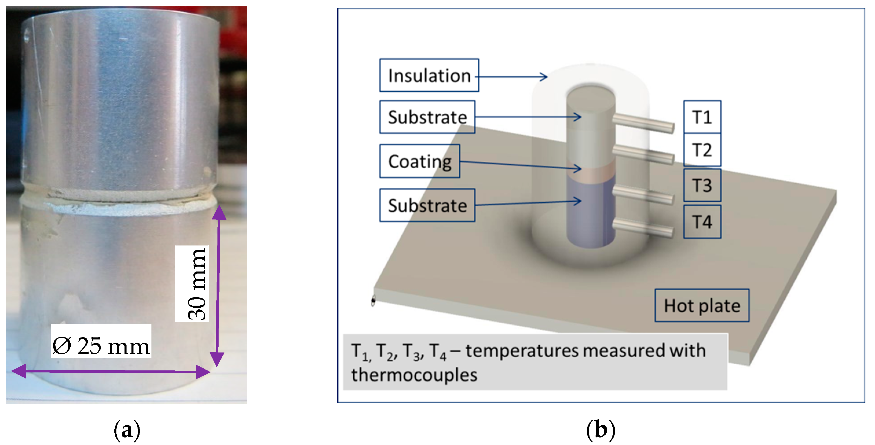
The thermal conductivity of the coatings was measured by a steady-state method and using a variation of the comparative technique described in [24]. In our case, the aluminum substrate of the coating was used as the reference standard. To ensure the uniformity of the heat flux across the surface of the coating, we used two samples with identical coating stacked on top of the other, with the two coatings in contact (see Figure 2). In this way, the region of interest is in the middle of the heat flux path rather than at the edge, and we can expect a more uniform and axial heat flux through the coating.
The steady-state methods have the advantage that they avoid the necessity of measuring the heat flux through the sample. Using the material of the piston or other engine part to be coated as standard in the comparative technique, we can directly measure the relative increase in thermal resistivity of the coating.
In order to ensure the axial symmetry of the heat flux as much as possible, we enclosed the ensemble of the samples in a thick insulating chamber built from refractory brick (Anorthite brick–Morgan Thermal Ceramics). The small space between the sample stack and the walls of the chamber were filled with grains of expanded perlite to reduce to a minimum the vertical convection from the hot plate to the top of the sample stack and to further reduce the radial component of the heat flux, which is one of the main sources of error in the steady-state methods.
The thermal conductivity of the insulating brick used is less than 0.2 W/(K·m) and the minimum thickness of the oven insulation (between the lateral surface of the sample stack and environment) is 100 mm. The outside temperature of the oven wall is about 60 °C when the temperature inside is in the range of 200–300 °C. With these values, the radial thermal flux can be estimated to be of the order of (2–4) × 10−2 W/cm2, whereas the axial thermal flux through our samples has values of the order of 4 W/cm2. With the radial flux of the order of 1% of the axial flux, we see that the assumption of axial thermal flux at steady state is a good approximation. Other sources of error are the distortion in the temperature field induced by the thermocouples and the extrapolation of the temperatures on the two sides of the coating from the temperatures measured by thermocouples, about 1 mm away from the surfaces.
The main advantage of the steady-state method for our specific investigation is that it better simulates the conditions of the actual working of the thermal barrier coating on the engine piston. The heating of the piston surface during the ignition is mainly due to conduction and not radiation and is relatively uniform over the surface of the piston (rather than spot-like). We used the same method (hot plate) to measure the temperature drop across the thermal barrier coating on an actual piston model.
In the steady-state method, the thermal flux q is assumed to be the same through the unknown sample and the known reference. The thermal flux is
Φ = K Δ T h ,
where ϕ is the thermal flux, K is the thermal conductivity, ΔT is the temperature difference and h is the distance between the two temperature sensors.
Assuming the same flux through both samples, we have
K 1 Δ T 1 h 1 = K 2 Δ T 2 h 2 ,
where “1” refers to the unknown sample and “2” refers to the reference sample.
Knowing K2 and measuring the temperature differences and the thicknesses, the value of K1 can be calculated. For our modified version of the method, we have two references, the two substrates of the coatings, stacked as in Figure 3 (insert). The temperatures measured with thermocouples embedded in the substrates (Figure 2b) are used to calculate the heat flux on each side of the coating and use the average of the two values to find the average flux:
Φ ave = Φ above + Φ below 2 ; Φ below = K s T 4 T 3 h 1 ;
Φ above = K s T 2 T 1 h 1
with the notations in Figure 3, and Ks is the thermal conductivity of the substrate.
Using this average value of the flux, we can calculate the thermal conductivity of the coatings as
K coating = Φ ave T 3 T 2 Δ h
where T’2 and T’3 are the temperatures at the interfaces between the substrate and the coatings. These values were extrapolated from the values T2 and respective T3 measured directly with the thermocouples and assuming a linear gradient of temperature along the substrate (Figure 3).
Using the expression for the average flux, the ratio between the thermal conductivity of the coating and that of the substrate can then be written as
K coating K s = Δ h 2 ( T 3 T 2 ) [ T 4 T 3 h 1 + T 2 T 1 h 2 ]
Precautions need to be taken to eliminate the effect of the contact thermal resistance at the interface between the two coatings as much as possible. We addressed this problem along two directions: first, we measured the thermal resistance between two samples with coatings of pure aluminum. As our coatings are all based on aluminum powder as the major component, this thermal resistance is a reasonable estimate of the thermal resistance between the two coatings. The calculation of the Kcoating was corrected by subtracting the contact thermal resistance from the thermal resistance of the coatings. The values of contact thermal resistance measured for the samples on 1-inch substrate were of the order of 15 K·mm2/W, whereas the total thermal resistance of the two coatings is in the range of 200–300 K·mm2/W. The effect of the contact thermal resistance can then be estimated to be less than 10%. To further reduce the effect of the thermal resistance, for some measurements we attached the two coatings through a thin layer of silver paint.
Thermal conductivity examination of piston models (Figure 4a,b) was made, with setup shown in Figure 4c. Models of flat piston heads were coated with the multilayer TBV and tested for determination of the temperature difference between the top of the coating and the substrate. The piston model was enclosed in an insulating chamber. One thermocouple was attached to the top of the coating (central area) with silver paint. The second thermocouple was inserted into a thin channel drilled about 1 mm below the substrate’s surface, along a radial direction.

2.3. Mechanical Properties and Structure Examination Procedures

As shown in the Introduction, the improved thermal efficiency results in measured gains in fuel economy and emissions reduction. To achieve these effects, ceramic-based TBCs are traditionally used to insulate combustion chambers due to the significantly reduced thermal conductivity as compared to engine block, head, and pistons metallic material. However, due to a mismatch of thermophysical properties between ceramics and the metals, these coatings are susceptible to failure far below the intended service lifetime of the engine [28,29]. Considering that the CTE of the examined intermetallic-based coatings matches the Al alloy substrate well, high values of their thermal shock resistance are foreseen. Nevertheless, a high brittleness of intermetallic compounds and the presence of some pores and cracks created at the synthesis process may be the reason for further accumulation of defects in intermetallic- and probably Al-based composite layers. Generally, a certain amount of porosity or microcracks seems to be favorable in achieving a high level of thermal shock resistance, because pores and microcracks accommodate deformation [29]. In addition, various gradient and layered structures are known to improve the performance of coatings [29]. In such systems, thermal stresses may be released, and the mechanical and thermal properties can be improved significantly. Normally, the thicker TBCs provide a greater temperature drop across the coatings. In addition, the increased thickness and number of layers of the coating will increase the total elastic strain energy stored, and hence the energy release rate for a crack [30]. Thus, the failure mechanisms that cause spallation of multilayered TBCs are expected to be different in some degree from those of the traditional TBCs.
It is known [18,19,24] that the failure of plasma-sprayed TBCs occurs in most cases by interface delaminating due to different thermomechanical properties of the coating and substrate and oxidation of the bond coat. In the case of multilayer intermetallic-based TBCs, the bonding strength between Al and intermetallic compounds is high due to gradual diffusion of Al to stainless steel particles and prevention the crack initiation at the interface. However, thermal shock and thermal fatigue behavior of multilayer coating itself have not been studied yet. Therefore, the aim of this experiment is to study the thermal shock behavior of the multilayer intermetallic-Al TBCs associated with different features of the microstructure.
The thermal shock behavior of TBCs was examined with resistance spot weld heat flux tests being performed with resistance spot welding gun, as shown on Figure 5.
In this new method of testing, TBC specimens were subjected to discrete temperature exposure; the developed experimental technique uses resistance spot weld heating to create a heat flux and to model the thermal shock conditions of TBC action. It allows for modeling of the thermal cycling of the samples with various temperatures due to permanent cooling of one specimen edge. Thermal cycling of the TBCs results in crack accumulation in the intermetallic and ZrO2 particles and particle–Al matrix interface (Figure 1c). This process depends on the temperature regime and number of cycles. The real temperature of the sample surface near to heat source is being registered permanently by infrared pyrometer at the surface area with axis AA. An example of temperature–time diagram is shown in Figure 6a. The thermal fatigue test at 500 and more cycles was made for Al plates coated with the multilayer TBC (Figure 5b). To estimate the crack accumulation dependence on thermal cycles, measurements of electrical resistance of the samples shown in Figure 5b were made by using a 4-probe (Kelvin) method, at a DC current of 3A.
The linear temperature distribution (Figure 5a) may be approved for calculation of the temperatures of the cross sections BB and CC based on modeling results shown in [21]. This conclusion allows one to define the procedure of layer-by-layer microhardness determination of the samples after thermal fatigue (TMF) test. The samples after TMF tests were cut and polished at the plane AA, in accordance with scheme shown in Figure 5. After microhardness measurements, the samples were ground and polished at the plane BB. Similar procedure was made to measure the microhardness in the plane CC.
After sintering, the samples were mounted in epoxy resin, sectioned perpendicularly to the surface of the coating, polished using standard metallographic technique and examined by optical microscopy and SEM with EDS. Optical light microscopy Leica DMI5000 M with a digital camera DFS 320 R2 was used for metallographic characterization. SEM and EDS examinations were made by microscope FEI, including EDS X-ray micro-analyzer manufactured by EDAX. The thicknesses of intermetallic layers as well as the layers’ morphology were studied for different sintering conditions. The microhardness testing with depth-sensing indentation was used to record the indentation load–depth diagram. Mechanical characterization of the TBCs was performed using a computer-controlled dynamic ultra-microhardness tester (Shimadzu DUH-W201S, Kyoto, Japan). The microhardness measurements were performed on mounted samples with a Vickers diamond indenter to evaluate the coating and substrate hardness at various indentation loads. Five hardness experiments were performed for each sample.

3. Results

3.1. LPCS Technology and Coatings General Characterization

Using the LPCS technique with a portable apparatus for the deposition of TBC multiphase composite coatings allows for both the spraying of various layers by two nozzles simultaneously and the deposition of the complex powder mixtures consisting of heavy and light, soft and hard particles to be performed in turn. The main LPCS technology parameters of air pressure, temperature and powder feed rate were chosen for each type of the coating to achieve the maximal deposition efficiency for each case (Table 1). To achieve the low thermal conductivity of the multilayer TBCs, Al-ZrO2 bond layers with high-content ZrO2 were deposited. The effect of ZrO2 in Al-ZrO2 powder mixture (30%, 40%, 50% and 75% ZrO2) on the coating porosity and composition was defined for coatings on Figure 7. The experimental results reveal that ZrO2 particles are being rebounded during coating formation, which results in lower ZrO2 content in the Al-ZrO2 coating as compared to that of powder mixture. The function CZrO2 = C(CZrO2 PM) linear approximation (Figure 7) demonstrates that about 30% of the ZrO2 particles are rebounded due to impingement with the substrate. Therefore, it is possible to use this approximation for the prediction of ZrO2 content in cold-sprayed Al-ZrO2 coating. One can note that the function ϴ = ϴ(CZrO2 PM) is approximated with a linear function similar to CZrO2 = C(CZrO2 PM). Thus, the pore formation process seems to be controlled by the interaction of ZrO2 and Al particles during their impingement with the substrate or coating being formed. The deposition efficiency dependence DE = DE(CZrO2 PM) (Figure 7) is characterized by a maximum at CZrO2 PM = 30% due to the possible activation effect of the substrate by hard ZrO2 particles during collision. The effect is similar to grit blasting described in [31]. However, a further increase of ZrO2 content in the powder mixture CZrO2 PM results in a fall of DE because of retarding Al particle deformation processes due to a decrease in Al particle content in the powder mixture. For this reason, a higher propellant gas (air) pressure and temperature are necessary to increase the particle velocity. One can note that the LPCS technology does not allow for a deposition efficiency of Al -based coating deposition higher than 30–40% [32] to be achieved, because of low particle velocity. However, the flexibility and portability of LPCS systems allows for them to be applied despite the above drawback.
Cold-spraying catalytic layers possesses some specific microstructure features because of the complexity of the powder mixture to be deposited. Admixing graphene particles to the electrolytic Cu powder for 8 h results in the formation of a graphene aggregates about 5–50 μm in size (Figure 8a). Some bright spots in the graphene aggregates can be seen at a magnification of 1500× (Figure 8b), which reveals the possible presence of small Cu particles. EDX examination results shown in Table 2 demonstrate the incorporation of the graphene on the Cu particles (spots 4,5). This effect shows that cold-spraying Cu-graphene agglomerates leads to the formation of composite with a certain content of graphene particles.
The LPCS examination results for Cu-2%Graphene powder mixture show low deposition efficiency (DE ≈ 6–8%) whilst the DE of Cu-10%Zn-2%Graphene powder mixture was about 18–20% for LPCS parameters shown in Table 1. The microstructural and EDX examination of the Cu-10%Zn-2%Graphene catalytic layer (Figure 9, Table 3) display the presence of Cu-, Zn- and carbon-containing phases.
The micrographs demonstrate the two types of porous structure: (i) pores of about 1–3 μm size in Zn phase and (ii) pores of 3–5 μm between Cu particles. The separate Zn particles are not seen in the Cu-10%Zn-2%Gr composite, which reveals that their bonding is due to cold-spray impact. The mutual Cu-Zn and Zn-Cu diffusion occurs during cold-sprayed Cu-10%Zn-2%Gr layer formation (Table 3). Some graphene particles are incorporated to porous Zn phase (spots 3,5, Table 3).

3.2. Thermal Parameters of the TBCs

3.2.1. Homogenous Coatings

The values of the thermal conductivity of the homogenous coatings (ZrO2–Al; Table 1) with uniform distribution of ZrO2 particles are shown in Table 4 and Figure 10 along with the theoretical prediction of the Maxwell–Euken-2 (ME2) model [33]. It is clearly seen that the thermal conductivity of two-phase TBC depends on the volume fraction of ZrO2. Three of the four results of TBC conductivity are situated very close to the theoretical curve (Figure 10). Even though two of the values are outside of the range of volume fractions measured by image processing, the offset is small enough to be explained by the imprecision of the relative area estimation on the microscope image.
Both theoretical estimation and experimental data provide a range of thermal conductivities of the ZrO2-Al composite due to variations of the volume fraction (Figure 7). For a range of ZrO2 fraction of 40–70%, the calculated effective conductivities are 9.3–12.6 W/(K·m). This is in good agreement with the experimental values obtained by measurement, as shown in Table 4 and Figure 10.

3.2.2. Layered Coatings

The estimate of the effective thermal conductivity of layered and homogeneous composites is defined based on the series model (Appendix A). The values for the thermal conductivity of the ZrO2-Al composite as measured in the present work were used together with a value of K = 14.0 W/(K·m) for stainless steel [34].
The range of calculated effective conductivities for a layered structure, using the conductivity values for the ZrO2-Al composite (Table 4) is 9.3–16.8 W/(K·m). Our measured values of 9.3 W/(K·m) are in the low end of this range, suggesting a high zirconia composite in the layered structure or/and a thermal conductivity of the stainless steel particulate layer lower than the bulk value found in literature.
As shown in [14], formation of the Fe-Al intermetallics during the reaction sintering process results in diminishing thermal conductivity of the multilayer SHS717-Al composites. Additionally, the last experimental results (Figure 10 and Table 4) demonstrated the low effective thermal conductivities of Al-ZrO2 homogeneous composites. Comparison of the examined TBCs (Figure 11) shows that the lowest thermal conductivity is obtained for 12-layer TBC with composition AISI304-(Al + 50%ZrO2). On the other hand, the influence of sintering temperature on the effective thermal conductivity Keff of Al-ZrO2 composite is small, Whilst the as-sprayed TBC has Keff ≈ 22–25 W/mK, Keff of the TBC sintered at 600 °C is twice lower (Keff ≈ 8.0–10.0 W/mK). Multilayer TBC effective thermal conductivity greatly depends on intermetallic formation reactions during sintering. The application of Al-ZrO2 layers as the bonding ones in the multilayer TBC allows for the additional diminishing of Keff up to Keff ≈ 6.0 W/mK.

3.3. TBCs Structure Morphology

As shown in [14,35], the thermophysical properties of multilayer TBCs are controlled by composite coating structure morphology. From this viewpoint, the microstructure of two constitutive layers needs to be examined: (i) the intermetallic-based layer being formed on the base of stainless steel particles, and (ii) the Al-based bond layer being formed during cold-spray consolidation of Al particles or Al-ZrO2 powder mixtures. The OM micrographs of Al-ZrO2 layers formed by cold-spray consolidation and sintering are shown on Figure 9. The relatively uniform dispersion of ZrO2 particles is observed in as-sprayed coating (Figure 12a). The microstructure at the magnification ×500 (Figure 12c) consists of Al splats formed due to plastic deformation during CS impact and ZrO2 particle aggregates formed due to fracture of spherical ZrO2 particles during CS impact. Some of the virgin spherical ZrO2 particles are seen. Sintering at a temperature of about 600 °C results in the partial melting of Al particles and the formation of Al-ZrO2 layered morphology (Figure 12b,d). The formation of layered morphology results in the diminishing of effective thermal conductivity of the Al-ZrO2 composite. Whist there is no considerable change in Keff of the Al-75%ZrO2 composite after sintering at 450–550 °C, a two-time fall of Keff is clearly observed after sintering at T = 575–600 °C (Figure 11).
Figure 13 demonstrates the SEM and OM micrographs of the layered TBCs of two types after sintering: (i) SHS717-Al and (ii) AISI304-(Al + 50%ZrO2). The Fe2Al5 intermetallic layer [35,36] formed on the SHS717 particles’ surface due to Al diffusion is clearly seen as the grey phase (Figure 13a,c). The bright core of some SHS717 particles is Fe-based phase, which did not react with Al yet. However, the 80–90% of SHS717 particle volume is transformed to Fe2Al5 intermetallic, which results in low effective thermal conductivity of the TBC.
The AISI304 particulate layer structure formation process during both cold spraying and sintering steps differs considerably from that of the SHS717 particle layer. The main SHS717 particle cold-spray consolidation mechanism is a super-deep penetration of hard SHS717 particles into the Al bonding layer [37].
In this case, a SHS717 particulate layer of approximately 50 μm thickness is obtained, and SHS717 particle fractures are observed [14]. Subsequent sintering of SHS717 steel particles with the Al bond layer results in the Fe2Al5 intermetallic formation reaction, which leads to the creation of some pores in Al (Figure 13c) due to the Kirkendall effect [14]. The AISI304 steel particle consolidation during CS is achieved due to a plastic deformation of the AISI304 particles. It results in the creation of the relatively dense particulate layer, as seen in Figure 13b. The AISI304 particulate layer thickness is controlled by CS parameters (particle velocity, powder feed rate, nozzle transverse speed, etc.). Subsequent sintering of the AISI304 layer results in the partial formation of Fe2Al5 and pores because of a lack of Al content in this layer. OM micrographs show the dense structure of AISI304 particulate layers after CS (Figure 13b) and porous morphology of the one AISI304 layer after sintering at 600 °C (Figure 13d). The pore formation due to the Kirkendall effect is intensive in this sintering temperature. The results of the more detailed SEM and EDS study of AISI 304-(Al + 50%ZrO2)-sintered TBC are shown in Figure 14.
The reactions of Fe-Al intermetallic formation are observed in both the AISI304 steel particles and Al bond layer. The diffusion of Al into steel particles results in the growth of intermetallic crystals only on the particle surfaces (Figure 14b). However, the steel core of the particle does not react with Al because of the retardation of the Al diffusion due to a lack of Al atoms at the steel particle–Al interface. On the other hand, some Fe atoms diffuse into Al, resulting in the formation of an intermetallic compound–Al mixture in the Al bond layer (Figure 14a,b); EDS analysis (Figure 14c,d) demonstrates less effectiveness of intermetallic formation reactions in the AISI304 steel layer as compared to that in the SHS717 particulate layer (Figure 13a,c).

3.4. Temperature Distribution in the Piston Models Coated with TBCs

Application of TBCs with low effective thermal conductivity results in a change of temperature distribution both in the combustion chamber and pistons. The temperature drops in the piston crown are important parameters allowing for the effectiveness of the piston the TBCs to be estimated. The experimental results of the AISI304-(Al + 50%ZrO2) 12-layer TBC tests obtained with the steady-state procedure described in Section 2.2 and Figure 4c are shown on Figure 15. The maximum testing temperature reached at the top surface of the coating was about 530 °C. The maximum temperature difference between the top surface of the coating and substrate was about 55 °C in a quasi-static situation.
The results for the piston with AISI304-(Al + 50%ZrO2) 12 layer TBC and without TBC are shown in the Figure 16.
The temperature evolution of the difference between the top and bottom of the piston model in a cyclic regime of heating and cooling with a period of 30 s is shown in Figure 17.

3.5. Influence of Thermal Cycling

The results of thermal cycling tests are shown on Figure 18 as the dependence of TBC electrical resistance on thermal cycles number (Figure 6a). The effect of SHS717-Al multilayer TBC electrical resistance increase with number of thermal cycles (Figure 18) may be explained by two main processes: (i) intermetallic phase formation and (ii) crack accumulation. The thermal cycling tests were made at two temperatures, 300 °C and 450 °C. Increasing the test heating temperature results in growing electrical resistance, probably due to the growth of the intermetallic layers on the SHS717 particles because of the Al diffusion into the Fe phase of the SHS717 particles.
The formation of intermetallics is shown on SEM images of microstructure (Figure 19a) and fracture topography (Figure 19b). Only a small portion of the Fe phase (bright at Figure 19, spot #1, Table 5) can be seen in the SHS717 particles. The main volume of these particles is transformed to intermetallics (grey phase).
On the other hand, the development of the Kirkendall effect of the Al atoms’ diffusion into SHS717 particles results in pore formation and crack generation (Figure 19) at the SHS717 particle–Al matrix interface. However, the ductility of the SHS717-Al composite layer remains high because of superior plastic properties of the Al matrix, which is seen on Figure 19. One can note that the chemical composition of the Al matrix (spot #3, Table 5) did not change during thermal cycling. Therefore, the average mechanical properties of the Al layers seem to remain unchanged.

3.6. Microhardness of TBCs

It is well-known that microindentation for microhardness determination has been intensively applied at the investigation of micromechanical behavior because the hardness is sensitive to the structure parameters, and indentation load–depth diagrams allow for the Young’s modulus of the material to be defined [38,39]. The examined layered intermetallic-metal TBCs are composites with unique structures, and they offer an attractive combination of properties from both component phases, i.e., high stiffness, high modulus, and low density of the intermetallics and high toughness of the metal. In order to measure the microhardness of various particles embedded into aluminum layers, the low loads need to be applied to avoid the influence of the soft aluminum matrix. Additionally, microhardness measurement at relatively high loads may result in the fracture of intermetallic particles [34]. For this reason, microhardness measurements were made at two normal loads: 1500 and 100 mN.
The results of microhardness measurements of the main phases of the examined layered intermetallic-Aluminum-ZrO2 composites are presented in Table 6. Analysis of these data reveals the following features of the structure formation of Al layers:
  • The microhardness of the cold-sprayed Al layer is lower than those of the substrate.
  • The increase in the sintering (heat treatment) temperature up to 575 °C leads to a fall in the microhardness of both the Al substrate and cold-sprayed Al and Al + ZrO2 layers due to similar softening processes.
  • A reaction diffusion at solid-state temperatures (500–575 °C) has a different influence on the hardness of the cold-sprayed Al layer of each composite.
  • Self high-temperature synthesis (SHS) reactions started at 600 °C result in a significant increase in the Al phase microhardness (up to values of the as-sprayed layers).
Porosity evaluation of Al layers made by image analysis show that the cold-sprayed Al layer in the Al-intermetallic composites has a porosity about 10–12%. Moreover, it is known [32] that the bonding strength between Al particles in the low-pressure cold-sprayed coating is about 40 MPa, which is lower than the Al yield strength. It affects the microhardness as well. Therefore, the porous Al layer with relatively low microhardness and strength allows for the development of better super-deep penetration of the steel particles forming an intermetallic layer at the cold-spray step. Some variation of the Al layer microhardness (Table 6), which results in a reaction diffusion at temperatures of 500–575 °C, reveals the alloying of Al solid solution with atoms of the various alloying elements containing in the SHS 717 particles. The images of indentation footprints of Al + ZrO2 composites shown on Figure 20 demonstrate the considerable hardening effect of ZrO2 particles, which depends on their real content and distribution in the soft Al matrix.

4. Discussion

One of the main advantages of the LPCS system is the ability to spray the various powder mixtures. LPCS technology parameters chosen on the basis of experimental data shown in Table 1 demonstrate that the LPCS method allows for both complex thermal barrier and catalytic coatings, and their combination, to be obtained. The coating structure and properties are well-controlled by propellant gas pressure and temperature, powder mixture composition and powder feeding rate. The main drawback of LPCS method is its low deposition efficiency in the range of 15–35%, which may be overcome up to 80% by the increase in gas pressure to 35 bar and using a middle-pressure cold-spraying system [40].
The experimental results demonstrate that LPCS technology allows for both complex powder mixtures and multilayer coatings to be deposited. Two types of powder mixtures are successfully deposited: Al-ZrO2 and Cu-Zn-Graphene. Some differences of coating structure formation mechanisms can be highlighted by comparison of the microstructures shown on Figure 1, Figure 9 and Figure 12. Deposition of Al-ZrO2 powder mixtures results in the breaking of the brittle ZrO2 particles due to impingement with the substrate and formation of a relatively homogeneous structure with a ZrO2 particle size of 3–10 μm (Figure 12a,c). Additionally, the Al-ZrO2 coating exhibits a much more pronounced flattened-splat microstructure (Figure 12c). The further liquid-phase sintering of cold-sprayed coating leads to Al and Al + ZrO2 composite layer formation (Figure 1a,b) due to the flow of the molten Al phase.
The as-sprayed Al-ZrO2 TBCs demonstrate the minimal effective thermal conductivity in the range of 8.0–10.0 W/mK, whilst the sintered intermetallic-based layered TBCs show Keff ≈ 5.0–8.0 W/mK (Figure 11). Intermetallic formation due to Al diffusion into steel particles leads to a considerable fall in thermal conductivity in the case of using Al bond layers. The intermetallics are formed due to reactive diffusion in alternatively stacked layers of two different metals. The intermetallic layers on the steel particles–Al matrix interface grow as a result of the annealing with the predetermined temperature and time. Therefore, the kinetics of the diffusion process is the key feature in controlling the properties of the synthesizing TBCs [14]. The intermetallic layer thickness on the steel particles (Figure 19) is proportional to growth kinetics, and the average thickness of the aluminide layer around the embedded particles may be used to calculate the kinetic parameters of the reaction diffusion. The further study and calculation of diffusion parameters will be made in future research.
The application of Al-ZrO2 composite bond layers results in the diminishing of the effect of intermetallics on thermal conductivity. The main possible reason of such an effect is the small thickness of intermetallic layers formed on the AISI304 steel particles during heat treatment because of the lack of Al diffusion from Al-ZrO2 and the Kirkendall pore effect (Figure 14). It is worth mentioning that the SHS717-Al TBCs demonstrate low thermal conductivity because the intermetallics occupy about 70–80% of the particle volume. Only a small portion of the particle volume in the core belongs to austenite (Figure 19, Table 5).
Multilayer TBCs with Al/Al-ZrO2 layers demonstrate high ductility due to the deformation of the Al matrix (Figure 19b). It is of great importance because the TBCs work in harsh loading and thermal shock conditions. The microhardness measurement data (Table 6) clearly show that microhardness of the Al layer falls after sintering at 500–575 °C due to the softening processes and increases after sintering at 625 °C due to the diffusion of Fe, Cr and other elements into the Al phase. In both cases, Al/Al-ZrO2 layers have high ductility and are able to stop crack generation and movement (Figure 13c). The results of thermal cycling’s influence on the electrical contact resistance (Figure 18) reveal that contact resistance is controlled by multilayer TBC structure formation processes such as intermetallic synthesis and pore formation. It is possible to share these effects based on the Arrhenius model, which will be made in future work.
Comparison of the effective thermal conductivity of cold-sprayed multilayer coatings with that of plasma-sprayed Yttria stabilized zirconia with 7–8 wt% (7–8% YSZ) commonly used as TBC material [16,41] demonstrates the similar values of Keff, a high thermal expansion coefficient similar to Al and the high ductility of the SHS717-Al composite due to the superior plastic properties of the Al matrix.
The main specific features of the catalytic coating structure (Figure 8 and Figure 9, Table 3) clearly demonstrate the opportunities for DFCS technology to create the layers of heterogeneous catalysts. At the present time, heterogeneous single-atom catalysts (SACs) with atomically dispersed metal atoms facilitate the maximized atom utilization efficiency to reduce the catalyst cost and achieve their use for many applications [42]. The experimental results of graphene NPs’ incorporation to the porous catalyst structure reveal the presence of Cu in the pores’ vicinity (spot 7 Table 3), which ensures high catalytic activity for a variety of hydrogenation and dehydrogenation reactions [43]. The Cu-Graphene catalytic layer is believed to reduce NOx in a combustion chamber by about 30–40%, similar to [44]. The real catalytic effectiveness of the Cu-Graphene coatings will be defined in future work.

5. Conclusions

LPCS technology combined with subsequent thermal treatment can be adjusted to produce TBCs with competitive thermal and mechanical properties. Multilayer TBCs in the system of yttrium-stabilized zirconia–aluminum–stainless steel combine the good thermal insulation properties of ceramics with the high thermal shock resistance of metals.
The composition of the multilayer ceramic–metal composite deposited by LPCS can be modified by including layers with catalytically active components for the reduction of undesired emissions and to improve the thermal efficiency of the engine. Additionally, the following conclusions are made based on experimental results:
  • The multilayer (Al-ZrO2)-SHS 717 cold-sprayed TBCs with the layer thickness of 40–50 µm each can be tailored to provide required thermal insulation properties in as-sprayed and sintered conditions.
  • Sintering the Al-SHS 717 composite results in the interface reactions of intermetallics formation, which results in a decrease in the effective thermal conductivity up to Keff ≈ 6.0W/mK, which is similar to that reported for yttria-stabilized zirconia (YSZ).
  • Deposition of Al-ZrO2 powder mixtures results in the breaking of the brittle ZrO2 particles due to impingement with the substrate and the formation of a relatively homogeneous structure with a ZrO2 particle size of 3–10 μm.
  • The application of TBCs with low effective thermal conductivity results in the temperature difference between the top surface of the coating and substrate of about 55 °C when the testing temperature of about 530 °C is reached at the top surface of the coating.
  • Another benefit of the developed multilayer TBCs is that thermal fatigue faced by the surface of the components can be reduced to a greater level.
  • The results of thermal cycling’s influence on the electrical contact resistance of intermetallic-based coatings demonstrate that the intermetallic synthesis and pore formation are the main processes of multilayer TBC structure formation during heating and cooling.
The main goals of future development of the multilayer thermal barrier–catalytic coatings are as follows: (i) the optimization of the sintering regime of the TBCs using advanced methods such as irradiation sintering, (ii) the detailed study of the Kirkendall effect and composite structure formation during both sintering and thermal cycling, and (iii) the definition of the real catalytic effectiveness of the cold-sprayed Cu-Graphene coatings for diesel engines.

Author Contributions

Conceptualization, J.T. and V.L.; data curation, R.G.M. and J.T.; formal analysis, M.P. and E.L.; investigation, M.P., E.L. and V.L.; methodology, V.L.; supervision, R.G.M. and J.T.; validation, V.L. and R.G.M.; writing and editing, V.L. and M.P. All authors have read and agreed to the published version of the manuscript.

Funding

Investigations were conducted within the NSERC project CRDPJ 508935-17 named: “Cluster: Novel quantitative nondestructive quality evaluation of advanced joining and consolidation manufacturing processes”.

Institutional Review Board Statement

Not applicable.

Informed Consent Statement

Not applicable.

Data Availability Statement

Not applicable.

Conflicts of Interest

The authors declare no conflict of interest.

Appendix A. Series Model for the Effective Thermal Conductivity of Layered Structures

For the layered coatings, we can use the values of thermal conductivity, calculated or measured, for the ZrO2-Al layer and the thermal conductivity for stainless steel from literature and calculate the effective thermal conductivity with a series model. As is shown in Figure 1c, the stainless steel layers are continuous and roughly parallel to each other, creating a sandwich structure with the ZrO2-Al composite between the layers.
A thermal resistance, Rθ can be defined by the equations
Φ = K Δ T h = Δ T R θ
R θ = Δ T Φ = h K
where h is the thickness of a flat layer with temperature difference ΔT between the two parallel surfaces.
The effective thermal resistance of a series structure is then the sum of the thermal resistances of various layers:
R θ = i R θ i = i Δ T i q = i h i K i = h K effective
and an effective thermal conductivity can be found as
K effective = h i h i K i
If the structure consists in multiple layers of just two types, as in our case, and if the thickness of the layers is fairly uniform, the effective thermal conductivity depends only on the parameters of one pair of layers. Adding more layers does not change the value of conductivity but it does change the value of the temperature drop across the structure. This is the reason for using multiple layer structures in the present work, which is aimed at increasing the temperature difference between the ignition chamber and the piston body.

References

  1. Yao, H.; Zhou, Z.; Xue, Y.; Zhou, Z.; Tan, Z.; He, D.; Wang, B.; Wang, L. Microstructure and thermal conductivity of wire-arc sprayed FeCrNbBSiC amorphous coating. J. Alloys Compd. 2019, 788, 514–521. [Google Scholar] [CrossRef]
  2. Balaji, D.; Maridurai, T. Experimental Investigation on Engine Performance and Emission in Diesel Engine by Alumi-num-Titanium Thermal Barrier Coating. Int. J. Chem. Sci. 2016, 14, 152–160. [Google Scholar] [CrossRef]
  3. Johnson, T.V. Review of diesel emissions and control. Int. J. Eng. Res. 2009, 10, 275–285. [Google Scholar] [CrossRef]
  4. Knecht, W. Diesel engine development in view of reduced emission standards. Energy 2008, 33, 264–271. [Google Scholar] [CrossRef]
  5. Yessian, S.; Varthanan, P.A. Optimization of Performance and Emission Characteristics of Catalytic Coated IC Engine with Biodiesel Using Grey-Taguchi Method. Sci. Rep. 2020, 10, 2129. [Google Scholar] [CrossRef]
  6. Poirier, D.; Lamarre, J.-M.; Legoux, J.-G. Thermal Cycling Assessment of Steel-Based Thermal Barrier Coatings for Al Protection. J. Therm. Spray Technol. 2014, 24, 175–184. [Google Scholar] [CrossRef]
  7. Beardsley, M.B. Thick thermal barrier coatings for diesel engines. J. Therm. Spray Technol. 1997, 6, 181–186. [Google Scholar] [CrossRef]
  8. Buyukkaya, E. Thermal analysis of functionally graded coating AlSi alloy and steel pistons. Surf. Coat. Technol. 2008, 202, 3856–3865. [Google Scholar] [CrossRef]
  9. Cerit, M.; Coban, M. Temperature and thermal stress analyses of a ceramic-coated aluminum alloy piston used in a diesel engine. Int. J. Therm. Sci. 2014, 77, 11–18. [Google Scholar] [CrossRef]
  10. Bobzin, K.; Zhao, L.; Öte, M.; Königstein, T. Effect of long-term heat-treatment at 1150 °C on the microstructure and properties of thermal barrier coatings based on ZrO2–4 mol.% Y2O3–1 mol.% Gd2O3–1 mol.% Yb2O3. Surf. Coat. Technol. 2017, 318, 142–146. [Google Scholar] [CrossRef]
  11. Yang, J.; Zhao, H.; Zhong, X.; Ni, J.; Zhuang, Y.; Wang, L.; Tao, S. Evolution of Residual Stresses in PS-PVD Thermal Barrier Coatings on Thermal Cycling. J. Therm. Spray Technol. 2018, 27, 914–923. [Google Scholar] [CrossRef]
  12. Harach, D.J.; Vecchio, K.S. Microstructure evolution in metal-intermetallic laminate (MIL) composites synthesized by reactive foil sintering in air. Met. Mater. Trans. A 2001, 32, 1493–1505. [Google Scholar] [CrossRef]
  13. Rohatgi, A.; Harach, D.J.; Vecchio, K.S.; Harvey, K.P. Resistance-curve and fracture behavior of Ti–Al3Ti metallic–intermetallic laminate (MIL) composites. Acta Mater. 2003, 51, 2933–2957. [Google Scholar] [CrossRef]
  14. Leshchinsky, E.; Sobiesiak, A.; Maev, R. Intermetallic Al-, Fe-, Co- and Ni-Based Thermal Barrier Coatings Prepared by Cold Spray for Applications on Low Heat Rejection Diesel Engines. J. Therm. Spray Technol. 2018, 27, 456–470. [Google Scholar] [CrossRef]
  15. Bai, Y.; Zhang, B.; Du, H.; Cheng, L.; Huiling, D. Efficient multiscale strategy for toughening HfB2 ceramics: A heterogeneous ceramic–metal layered architecture. J. Am. Ceram. Soc. 2020, 104, 1841–1851. [Google Scholar] [CrossRef]
  16. Chattarki, A.R.; Basavakumar, K.G. Thermal Barrier Coating on IC Engines: A Review. In Recent Trends in Mechanical Engineering; Springer: Singapore, 2021; pp. 47–68. [Google Scholar] [CrossRef]
  17. Shrirao, P.N.; Pawar, A.N. Evaluation of performance and emission characteristics of turbocharged diesel engine with mullite as thermal barrier coating. Int. J. Eng. Technol. 2011, 3, 256–262. [Google Scholar]
  18. Nash, C.P.; Dupuis, D.P.; Kumar, A.; Farberow, C.A.; To, A.T.; Yang, C.; Wegener, E.C.; Miller, J.T.; Unocic, K.A.; Christensen, E.; et al. Catalyst design to direct high-octane gasoline fuel properties for improved engine efficiency. Appl. Catal. B Environ. 2021, 301, 120801. [Google Scholar] [CrossRef]
  19. Bannikov, M.G.; Draper, P.H.; Chattha, J.A.; Vasilev, I.P.; Gavrilenko, P.N. Reduction in NOx emission of diesel engines by in-cylinder catalysis. Proc. Inst. Mech. Eng. Part A J. Power Energy 2003, 217, 101–106. [Google Scholar] [CrossRef]
  20. Darolia, R. Thermal barrier coatings technology: Critical review, progress update, remaining challenges and prospects. Int. Mater. Rev. 2013, 58, 315–348. [Google Scholar] [CrossRef]
  21. Ghadami, F.; Aghdam, A.S.R.; Ghadami, S. A comprehensive study on the microstructure evolution and oxidation resistance of conventional and nanocrystalline MCrAlY coatings. Sci. Rep. 2021, 11, 875. [Google Scholar] [CrossRef]
  22. Ghadami, S.; Aghdam, A.S.R. Mechanism of the oxide scale formation in thermally-sprayed NiCoCrAlY coatings modified by CeO2 nanoparticles. Mater. Today Commun. 2020, 24, 101357. [Google Scholar] [CrossRef]
  23. Jokar, A.; Ghadami, F.; Azimzadeh, N.; Doolabi, D.S. A novel approach to the protection of internal passageways of gas turbine blades by aluminide coating: Evaluation of oxidation behavior. Mater. Corros. 2022, 1–19. [Google Scholar] [CrossRef]
  24. Tritt, T.M.; Weston, D. Measurement techniques and considerations for determining thermal conductivity of bulk materials. In Thermal Conductivity—Theory, Properties and Applications; Tritt, T.M., Ed.; Springer: Boston, MA, USA, 2004; pp. 187–198. [Google Scholar]
  25. Yüksel, N. The Review of Some Commonly Used Methods and Techniques to Measure the Thermal Conductivity of Insu-lation Materials. In Insulation Materials in Context of Sustainability; Almusaed, A., Almssad, A., Eds.; IntechOpen: London, UK, 2016. [Google Scholar]
  26. Buck, W. Thermal Conductivity and heat capacity (8.1). In Handbook of Materials Measurement Methods; Czichos, H., Saito, T., Smith, L., Eds.; Springer: Berlin, Germany, 2006. [Google Scholar]
  27. Wakisaka, Y.; Inayoshi, M.; Fukui, K.; Kosaka, H.; Hotta, Y.; Kawaguchi, A.; Takada, N. Reduction of Heat Loss and Improvement of Thermal Efficiency by Application of “Temperature Swing” Insulation to Direct-Injection Diesel Engines. SAE Int. J. Eng. 2016, 9, 1449–1459. [Google Scholar] [CrossRef]
  28. Guo, H.; Vaßen, R.; Stöver, D. Thermophysical properties and thermal cycling behavior of plasma sprayed thick thermal barrier coatings. Surf. Coat. Technol. 2005, 192, 48–56. [Google Scholar] [CrossRef]
  29. Hutchinson, J.; Suo, Z. Mixed mode cracking in layered materials. Adv. Appl. Mech. 1991, 29, 63–191. [Google Scholar] [CrossRef]
  30. Gilbert, A.; Kokini, K.; Sankarasubramanian, S. Thermal fracture of zirconia–mullite composite thermal barrier coatings under thermal shock: An experimental study. Surf. Coat. Technol. 2008, 202, 2152–2161. [Google Scholar] [CrossRef]
  31. Raoelison, R.; Xie, Y.; Sapanathan, T.; Planche, M.; Kromer, R.; Costil, S.; Langlade, C. Cold gas dynamic spray technology: A comprehensive review of processing conditions for various technological developments till to date. Addit. Manuf. 2017, 19, 134–159. [Google Scholar] [CrossRef]
  32. Leshchynsky, V. Theoretical description of cold spray process. In Cold Gas Dynamic Spray; Maev, R.G., Ed.; CRC Press: Boca Raton, FL, USA, 2016; pp. 25–44. [Google Scholar]
  33. Carson, J.K.; Lovatt, S.J.; Tanner, D.J.; Cleland, A.C. Thermal conductivity bounds for isotropic, porous materials. Int. J. Heat Mass Transf. 2005, 48, 2150–2158. [Google Scholar] [CrossRef]
  34. Leshchinsky, E. Cold Sprayed Intermetallic Thermal Barrier Coatings. Ph.D. Thesis, University of Windsor, Windsor, MO, Canada, 2013. [Google Scholar]
  35. Sheikh, S.; M’Saoubi, R.; Flasar, P.; Schwind, M.; Persson, T.; Yang, J.; Llanes, L. Fracture toughness of cemented carbides: Testing method and microstructural effects. Int. J. Refract. Met. Hard Mater. 2015, 49, 153–160. [Google Scholar] [CrossRef]
  36. Gedevanishvili, S.; Deevi, S.C. Processing of iron aluminides by pressure less sintering through Fe+Al elemental route. Mater. Sci. Eng. A 2002, 325, 163–176. [Google Scholar] [CrossRef]
  37. Klinkov, S.V.; Kosarev, V.F.; Rein, M. Cold spray deposition: Significance of particle impact phenomena. Aerosp. Sci. Technol. 2005, 9, 582–591. [Google Scholar] [CrossRef]
  38. Li, J.; Li, F.; Xue, F.; Cai, J.; Chen, B. Micromechanical behavior study of forged 7050 aluminum alloy by microindentation. Mater. Des. 2012, 37, 491–499. [Google Scholar] [CrossRef]
  39. Xue, F.; Li, F.; Cai, J.; Yuan, Z.; Chen, B.; Liu, T. Characterization of the elasto-plastic properties of 0Cr12Mn5Ni4Mo3Al steel by microindentation. Mater. Des. 2012, 36, 81–87. [Google Scholar] [CrossRef]
  40. PX & EPX—Integrated Powder Feed System. Available online: www.supersonicspray.com/support/documentation (accessed on 27 June 2022).
  41. Hossain, M.K.; Rubel, M.; Akbar, A.; Ahmed, M.H.; Haque, N.; Rahman, F.; Hossain, J.; Hossain, K.M. A review on recent applications and future prospects of rare earth oxides in corrosion and thermal barrier coatings, catalysts, tribological, and environmental sectors. Ceram. Int. 2022, in press. [Google Scholar] [CrossRef]
  42. Xu, Z.; Ao, Z.; Yang, M.; Wang, S. Recent progress in single-atom alloys: Synthesis, properties, and applications in environmental catalysis. J. Hazard. Mater. 2021, 424, 127427. [Google Scholar] [CrossRef]
  43. Shan, J.; Liu, J.; Li, M.; Lustig, S.; Lee, S.; Flytzani-Stephanopoulos, M. NiCu single atom alloys catalyze the C H bond activation in the selective non- oxidative ethanol dehydrogenation reaction. Appl. Catal. B Environ. 2017, 226, 534–543. [Google Scholar] [CrossRef]
  44. Venkatesan, S.; Uday, D.S.; Hemant, B.K.; Goud, K.R.K.; Kumar, G.L.; Kumar, K.P.I.C. Engine emission reduction by copper oxide catalytic converter. In Proceedings of the IOP Conference Series: Materials Science and Engineering, Sathyabama University, Chennai, India, 7–9 July 2016. [Google Scholar] [CrossRef] [Green Version]
Figure 1. Optical microscopy structure of the coatings. (a) two-phase Al-ZrO2 homogenous structure; (b) same as (a) with the ZrO2 area in red; (c) AISI304-(Al + ZrO2) three-phase layered coatings; (d) Cu-Graphene catalytic layer deposited on the multi-layer TBC. Some of the graphene aggregates are shown by white arrows.
Coatings 12 01332 g001
Figure 2. Experimental details. (a) Samples with TBCs attached by silver paint; (b) the hot plate experimental setup with the positions of the thermocouples.
Coatings 12 01332 g002
Figure 3. Typical temperature variation across the two samples with TBC at steady state. The temperatures T2 and T3 are measured directly with thermocouples, whereas T’2 and T’3 are extrapolated values.
Coatings 12 01332 g003
Figure 4. Experiments on piston head model: (a) piston model without coating; (b) piston model with multilayer coating; (c) experimental setup used to test the thermal properties of TBCs on piston head model; (d) piston model with thermocouple attached to the top coating.
Coatings 12 01332 g004
Figure 5. Heat flux tests to examine the TBC thermal fatigue. (a) Schematics; (b) sample for TBC spot electrical resistance measurements after thermal cycling.
Coatings 12 01332 g005
Figure 6. Pyrometer data of surface temperature measurements at the section AA: (a) the steady state process (LumaSense Technologies Co software); (b) appearance of the first temperature peak [14].
Coatings 12 01332 g006
Figure 7. Al-ZrO2 coating characterization. Approximation curves are shown by dotted lines.
Coatings 12 01332 g007
Figure 8. SEM of Cu particles and graphene aggregates in Cu-Gr powder mixture. (a) magnificaton 800×, (b) magnification 2000×; the EDS spots are shown.
Coatings 12 01332 g008
Figure 9. SEM micrograph of Cu-10%Zn-2%Graphene catalytic layer. (a) Sample topography, (b) the EDS analysis spots.
Coatings 12 01332 g009
Figure 10. The ME2 curve with the experimental values of thermal conductivity for the homogenous coatings (blue points).
Coatings 12 01332 g010
Figure 11. Effective thermal conductivity vs. sintering temperature. Series 1: 6-layer TBC SHS717-Al; Series 2: 12-layer TBC SHS717-Al [14]; Series 3: 12-layer TBC AISI304-(Al + 50%ZrO2); Series 4: one-layer Al + 75%ZrO2 TBC; Series 5: one-layer Al + 50%ZrO2 TBC.
Coatings 12 01332 g011
Figure 12. (a,c) OM micrographs of Al-75%ZrO2 coating after cold spraying (magnification ×250); (b,d) following sintering at 600 °C (magnification ×500).
Coatings 12 01332 g012
Figure 13. Microstructure topography after CS (b) and sintering at 600 °C (a,c,d): (a) SEM micrograph of SHS717-Al 3-layer TBC; (b) OM micrograph of AISI304-(Al + 50%ZrO2) 12-layer TBC after CS; (c) SEM micrograph of SHS717-Al 6-layer TBC fractured surface; (d) OM micrograph of AISI304-(Al + 50%ZrO2) 12-layer TBC, magnification ×2500.
Coatings 12 01332 g013
Figure 14. SEM micrograph and EDS of AISI304-(Al + 50%ZrO2) 12-layer TBC: (a) SEM image; (b) EDS map of element distribution; (c) result of elemental analysis by EDS.
Coatings 12 01332 g014
Figure 15. Temperatures recorded on top of the (T1) and below the surface (T2) during the steady heating of the piston model with AISI304-(Al + 50%ZrO2) 12-layer TBC coating.
Coatings 12 01332 g015
Figure 16. Heating curves for piston model with water cooling, continuous regime: (a) piston model with no TBC; (b) piston model with TBC. (T1 is the temperature measured at the top of the coating and T2 is the temperature measured at the bottom surface of the piston model; the temperature difference is shown on the right-hand side vertical axis).
Coatings 12 01332 g016
Figure 17. Temperatures of the top and bottom of the AISI304-(Al + 50%ZrO2) 12-layer TBC-coated piston model during a 30 s cycle of heating and cooling.
Coatings 12 01332 g017
Figure 18. Electrical resistance of SHS717-Al multilayer TBC (coating #2, Table 1).
Coatings 12 01332 g018
Figure 19. SEM images of SHS717-Al TBC: (a) microstructure; (b) fracture surface topography.
Coatings 12 01332 g019
Figure 20. Optical images of indentation footprints of Al + ZrO2 composites sintered at 550 °C during 1 h: (a)—Al matrix of Al + 40%ZrO2; (b)—ZrO2 particles in Al + 75%ZrO2 composite.
Coatings 12 01332 g020
Table 1. Cold-spraying technology and deposited coating parameters.
Coating Number and DesignationPowder Mixture Composition,
Volume %
Cold-Spray Technology ParametersAverage Thickness of LayersPorosity,
%
Air T,
°C
Air Pressure,
Bar
Powder Feed Rate,
g/s
Nozzle Transverse Speed mm/sStep Size,
mm
Number of
Layers
Average Thickness per Pass μmTotal Thickness,
μm
1. Al + ZrO2 thermal barrier coating (TBC)1a: 30% ZrO23006.01.030.01.011004008.0
1b: 40% ZrO23006.01.030.01.0110040010.0
1c: 50% ZrO23508.00.530.00.517035015.0
1d: 75% ZrO23508.00.530.00.517035020.2
2. SHS717-Al layered TBCAl layer3506.01.030.04.061509007.5
SHS 717 layer3508.00.530.04.0650300-
3. SHS717-(Al + ZrO2) layered TBCAl + 50% ZrO2 layer3508.00.530.04.0615090015.3
SHS 717 layer3508.00.530.04.0650300-
4. AISI304-(Al + ZrO2) layered TBC4a:Al + 50% ZrO2 layer3508.00.530.04.0615090015.4
4b:Al + 75% ZrO2 layer3508.00.530.04.0615090020.5
AISI304 layer3508.00.530.04.065533020.3
5. Catalytic layerCu-10% Zn-2% Graphene 5506.00.530.02.515015020.7
Table 2. EDX of Cu-Graphene powder mixture.
Spot NumberElementWeight %Atomic %
EDS Spot 1C K100100
EDS Spot 2,3C K100100
EDS Spot 4C K7.5130.04
CuK92.4969.96
EDS Spot 5C K39.6575.37
O K2.763.94
CuK57.6020.70
EDS Spot 6C K78.4882.93
O K21.5217.07
Table 3. EDX of Cu-10%Zn-2%Graphene catalytic layer.
Spot NumberElementWeight %Atomic %
EDS Spot 1C K2.7412.98
CuK87.2078.24
ZnK10.078.78
EDS Spot 2CuK54.6955.40
ZnK45.3144.60
EDS Spot 3CuK91.4391.65
ZnK8.578.35
EDS Spot 4O K10.0731.10
CuK41.4532.25
ZnK48.4836.65
EDS Spot 5C K13.4133.68
O K18.5134.91
ZnK68.0831.41
EDS Spot 6ZnK100.00100.00
EDS Spot 7C K8.8730.51
O K6.0415.60
CuK7.855.10
ZnK77.2348.79
Table 4. Experimental results for 1” diameter samples coated with TBCs.
Coat No.CompositionStructureK
[W/(K·m)]
1AZrO2–Al (9:1)Single layer12
1BZrO2–Al (9:1)Single layer8.4
1CZrO2–Al (9:1)Single layer12.2
1DZrO2–Al (9:1)Single layer18.0
4AAISI304-(ZrO2-Al)6 layers each9.3
4BAISI304-(ZrO2-Al)6 layers each9.3
Table 5. EDX analysis results (Figure 19b).
ElementSpot#1Spot#2Spot#3
-Weight %Atomic %Weight %Atomic %Weight %Atomic %
C03.0912.79----
Al07.2813.4260.8773.61100.00100.00
W09.6302.61----
Mo03.9202.03----
Cr20.4819.6009.4105.90--
Mn02.4002.1701.9301.15--
Fe53.2047.3822.4413.11--
Si--05.3506.22--
Table 6. Microhardness of coatings after heat treatment at various temperatures.
Thermal Barrier Layer DesignationHeat Treatment Temperature,
T °C
Al SubstrateCold-Sprayed Al/(Al50%ZrO2) LayerSHS717/AISI304 Particle
Core
SHS717/AISI304 Particle–Al/(Al50%ZrO2) Interface Area
SHS 717-Al20110.391.3918146.9
5009457.92343.9132.6
55094.2661387321.4
57576.648.61388.8233.78
60089.178.02687-
62574.891.75997.86-
AISI 304-(Al + 50%ZrO2)20107.9145.4304.6150.2
50097.3130.5285.2170.8
55078.61125.8270.8-
575-132.7261.4182.7
600-122,3340.3234.07
625-120.4486.9157.88
Publisher’s Note: MDPI stays neutral with regard to jurisdictional claims in published maps and institutional affiliations.

