Article

Study of Co-Deposition of Tantalum and Titanium during the Formation of Layered Composite Materials by Magnetron Sputtering

by
Elena Olegovna Nasakina
*,
Maria Andreevna Sudarchikova
,
Konstantin Yurievich Demin
,
Alexandra Borisovna Mikhailova
,
Konstantin Vladimirovich Sergienko
,
Sergey Viktorovich Konushkin
,
Mikhail Alexandrovich Kaplan
,
Alexander Sergeevich Baikin
,
Mikhail Anatolyevich Sevostyanov
and
Alexei Georgievich Kolmakov
Laboratory of Durability and Plasticity of Metal and Composite Materials and Nanomaterials, A.A. Baikov Institute of Metallurgy and Material Science RAS (IMET RAS), Institution of Russian Academy of Sciences, Leninsky Prospect, 49, 119991 Moscow, Russia
*
Author to whom correspondence should be addressed.
Coatings 2023, 13(1), 114; https://doi.org/10.3390/coatings13010114
Submission received: 5 December 2022 / Revised: 23 December 2022 / Accepted: 27 December 2022 / Published: 7 January 2023

Abstract

:
Composite materials "base–transition layer–surface metal layer (Ta/Ti)" were produced using a complex vacuum technology including magnetron sputtering. The structure (by scanning electron microscopy, Auger electron spectroscopy, X-ray diffractometry) and mechanical properties were studied. An almost linear increase in the thickness of both the surface and transition layers was observed with increasing deposition time and power; however, the growth of the surface layer slowed down with increasing power above some critical value. The transition zone with the growth of time stopped growing upon reaching about 300 nm and was formed approximately 2 times slower than the surface one (and about 3.5 times slower with power). It was noted that with equal sputtering–deposition parameters, the layer growth rates for tantalum and titanium were the same. In the sample with a Ta surface layer deposited on titanium, a strongly textured complex structure with alpha and beta Ta was observed, which is slightly related to the initial substrate structure and the underlying layer. However, even at small thicknesses of the surface layer, the co-deposition of tantalum and titanium contributes to the formation of a single tantalum phase, alpha.

1. Introduction

Tantalum (Ta), titanium (Ti) and their compounds have not ceased to arouse functional interest for humans for decades as a material applicable in various spheres of human life: in optics (transmitting, antireflection, filtering, reflecting, absorbing media) [1,2,3], electronics (conductors, semiconductors, dielectrics) [4,5], machine and instrument making, construction and everyday life (tribological, wear-resistant, functional, protective coatings, resistant to aggressive environments, decorative, antibacterial, etc.) [6,7,8,9,10], environmental cleanup and agriculture [11,12,13], medicine (biocompatible, adhesive intermediates) [14,15,16,17,18,19,20,21,22,23,24,25], and etc., due to its significant characteristics (biocompatibility, resistance to aggressive media, wear resistance, electrical, light and thermal conductivity, photocatalytic activity, radiopacity, strength and/or plasticity, etc.), also including in the form of coatings, thin films and surface layers.
Composites, including layered ones, are unique structures that allow effectively combining, improving and forming in radically new characteristics compared with the original components that are inaccessible to classical materials, which has led to their widespread use [26,27,28,29,30,31,32,33,34,35,36,37,38,39,40,41,42,43]. In particular, composite structures with surface layers such as TaTiON for optics and electronics, TiTa (at a shape memory ratio), Ta/Ti/TiN/Ti/DLC (diamond-like carbon) and Ta/Ti/DLC for implantology, TaN-(Ta,Ti)N-TiN-Ti for energy, etc. are gaining importance in the modern world [44,45,46,47]. For example, to obtain corrosion-resistant biocompatible coatings on superelastic alloys, similar in mechanical properties to living tissues, but containing toxic elements, a mixture of tantalum and titanium is used, because at a certain ratio, this mixture also exhibits similar mechanical characteristics [45]. This mixture is obtained by depositing tantalum layers on a titanium-containing substrate by the magnetron method with intermittent mixing by cycling electron-beam additive technique. The process seems to be quite complicated and requires the preliminary presence of titanium in the substrate. That is, the problem of joint deposition of these two metals (in series or in parallel) is now quite relevant.
A fairly popular method for creating composite surfaces is physical deposition in a vacuum is vacuum ion-plasma methods, especially a variety of magnetron sputtering, which allows, at a fairly low cost of time and resources, effectively obtaining high-quality thin surface layers and coatings of various compositions and structures on a substrate of almost any nature and geometry [48,49,50,51,52,53,54,55,56,57,58,59]. At the same time, the resulting layers parameters are directly connected with the time and power of sputtering, the deposition distance, the state of the substrate surface and other process parameters, which can vary within wide limits. They determine the phase composition of the new surface. If a multi-component spray system used, the variability of the results increases many times over.
The purpose of this work was to study the features of substance deposition in the region of magnetron sputtering of a tantalum-titanium binary system under varying process conditions and their relationship with the structure of the layers formed during vacuum ion-plasma production of layered metal composite materials.

2. Materials and Methods

In this work, the creation of layered composite materials of various nature was carried out using ion-vacuum technologies by forming surface layers of tantalum and titanium on various substrates (base material) using a DC magnetron in an argon gas environment at a Torr International facility (New Windsor, NY, USA).
The use of magnetron sputtering to create surface layers makes it possible to avoid overheating of the substrate by bombarding electrons due to their retention at the sputtered target, which is extremely important for substrate materials with low melting temperatures or a phase structure sensitive to temperature changes, such as, for example, in superelastic titanium alloys: heat treatment makes it possible to change static properties and cyclic loading under operating conditions with a broad diapason of deformations and is essential for the stabilization of properties, creation and successful application of the product.
The formation of a new surface of a mixed composition on the substrate was carried out in two ways: sequential deposition of a layer from one metal onto a layer from another and simultaneous deposition of both metals. To test the sputtering modes before obtaining composite materials with a mixed surface, surface layers of tantalum or titanium were deposited in the form of separate single layers.
Disks made of chemically pure tantalum, titanium, or a bicomponent structure were used as a sputtered target. As a basis for the composites, plates made of titanium alloys TiNi, TiNbMo, TiNbZr, steel, copper, titanium, etc., 10 mm × 10 mm × 0.5 mm in size, were used. The plates were treated with abrasive sandpaper (grit from 400 to 800) and polished (to a mirror surface) with the addition of diamond suspensions with a particle size of 3, 1 and 0.05 microns to remove flat dents and defects. The depth of surface defects after treatment did not exceed 1 μm. Substrates made of steel, copper and glass/SiO2 are of interest as a basis for the production of functional materials for a broad diapason of applications (electronics, optics, structural materials, etc.), and superelastic titanium alloys in medicine. For cleaning, activation and polishing, the substrate surface was bombarded with argon ions at U = 900 V and I = 80 mA prior to deposition, i.e., preliminary ion etched.
Surface layers were obtained under the following process conditions (deposition parameters): (1) current I ~ 400–1100 mA, voltage U ~ 360–700 V (power supply power ≈ 135–600 W); (2) deposition time from 5 to 120 min; (3) deposition distance (distance from the target to the substrate) 40–250 mm. The temperature on the substrate surface did not exceed 150°C. The working and residual pressures in the vacuum chamber were ~0.4 and 4 × 10⁻⁴ Pa, respectively.
Morphology, type of destruction during mechanical tests and layer-by-layer elemental composition (including using transverse sections) of the surface of materials were studied using a scanning electron microscope TESCAN VEGA II SBU (TESCAN, Brno, Czech Republic) equipped with an attachment for energy-dispersive analysis INCA Energy (Oxford Instruments, High Wycombe, UK), a JAMP-9500F Auger electron spectrometer (JEOL, Tokyo, Japan) in combination with ion etching under argon bombardment at an angle of 30°, and a GDS 850 A glow-discharge atomic emission spectrometer (Leco, St Joseph, MI, USA) with a high-frequency alternating current source.
X-ray diffraction patterns were obtained on ARL X′TRA (Thermo Fisher Scientific) SARL, Ecublens, Switzerland) and UltimaIV (Rigaku, Tokyo, Japan) instruments, in CuKα radiation in parallel beam geometry. The device was calibrated according to the standard sample NIST SRM-1976a, the error in the position of reflections did not exceed 0.01 °2θ. The crystal lattice parameter was refined by extrapolation to θ = 900 using the Nelson-Riley method in the Origin-2017 program (OriginLab Corporation, Northampton, MA, USA), the magnitude of the crystal lattice microdeformation of the main phase was determined using the Williamson–Hall method in the HighScore Plus program (version 3.0.3, PANanalytical, Almelo, the Netherlands). The quantitative content of crystalline phases was estimated by the method of corundum numbers. Before the study, the surface of the samples was cleaned by washing in ethyl alcohol and distilled water.
Static tests were carried out on a universal testing machine INSTRON 3382 (Instron Corp., Norwood, MA, USA) with a stretching speed of 1 mm/min with an accuracy of the traverse speed of ± 0.2% of the value of the set speed. The processing of test results in determining the characteristics of mechanical properties was carried out in accordance with GOST RF standard 10446-80 (ISO 6892-1:2019(E)) using INSTRON Bluehill 2.0 software. For each experimental point, 3–5 samples were tested. The values of yield strength, tensile strength, relative elongation and Young’s modulus were determined.

3. Results and Discussion

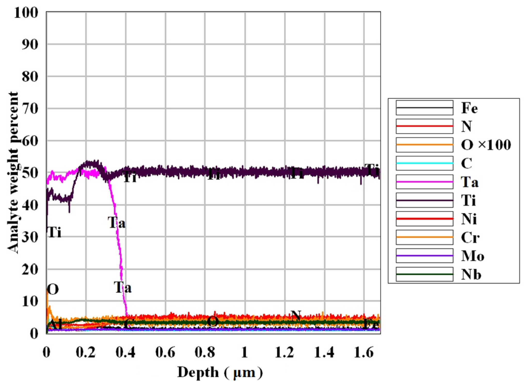
In general, identical results were obtained when studying the composition of the obtained surface monolayers: the upper surface layer is enriched with oxygen to a depth of 20 nm due to active surface adsorption; the deeper layer consisted only of the deposited element; between it and the substrate there was a transition layer (containing elements of both the substrate and the deposited substance), which was also enriched with oxygen. Depending on the deposition parameters of several successive layers, regularities were obtained identical to those of the single layer’s formation, and transition zones were also observed between the layers of deposited metals (Figure 1). Even when using a titanium alloy substrate, regions of layer-by-layer deposition of titanium (without other alloy elements) and tantalum can be noted on the results of the energy-dispersive analysis of a multilayer composite material (Figure 2).
The generation of the transition layer can be considered as a result of magnetron sputtering, when sputtered particles both condense on the substrate surface, and approach it with some additional energy, and their contact leads to a number of particle interactions [60,61]: “driving in” of sputtered atoms and ions, their “knocking out” (interaction can be elastic and inelastic, with or without energy transfer) and re-deposition or, conversely, the surface particles penetration (both the substrate and previously deposited sputtered elements) into the substrate subsurface structure, the formation of radiation defects stimulated mutual diffusion of the substrate elements and of the deposited layer atoms at their interface, etc. This means that the particles brought into the mobilized state (the deposited substance and the area of the substrate surface), repeatedly colliding and chaotically moving on the substrate surface or near it, are constantly mixed. Ultimately, the surface area is so saturated with the sprayed substance that its interaction with new flows of atoms and ions leads to the formation of a pure surface layer of the composite.
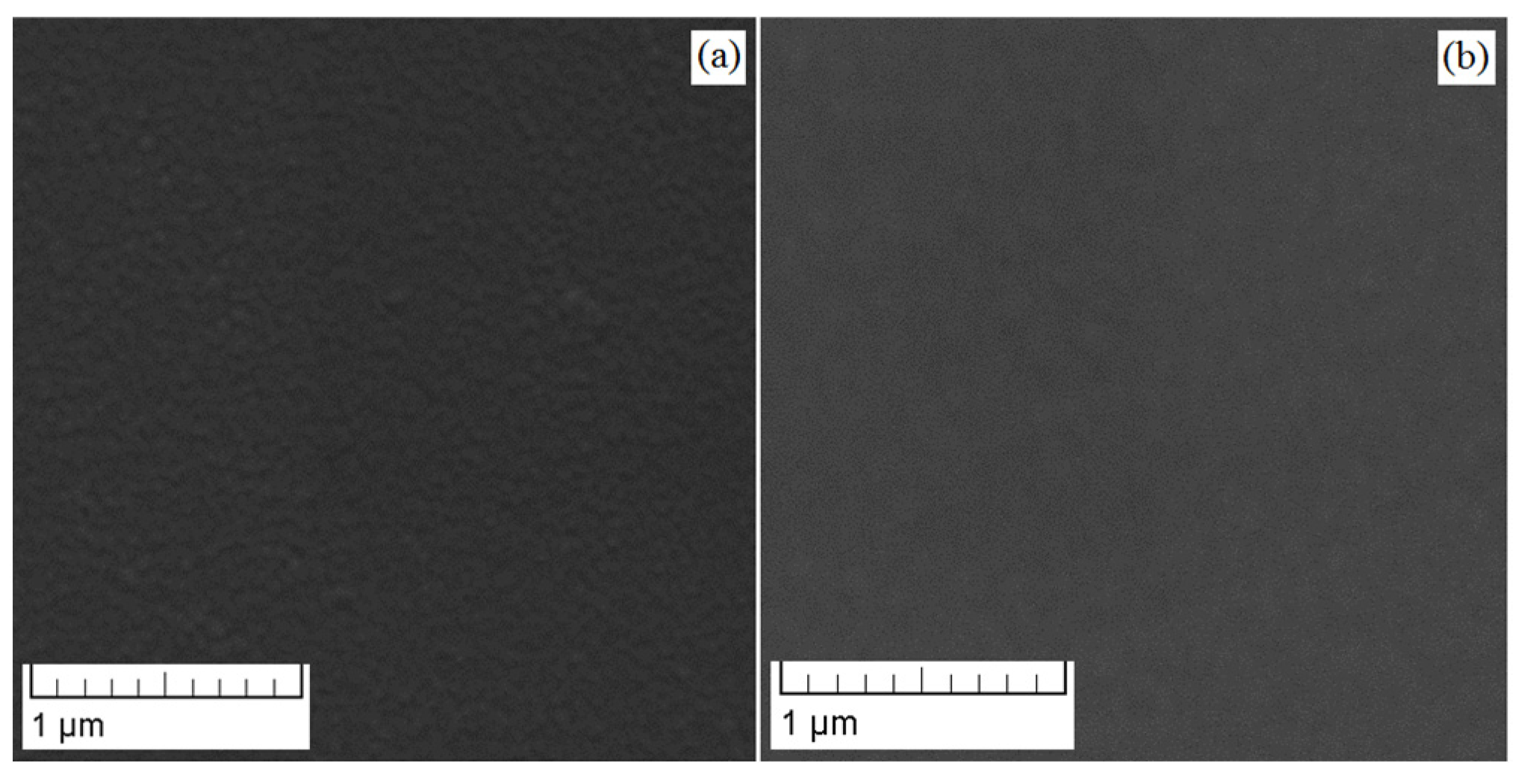
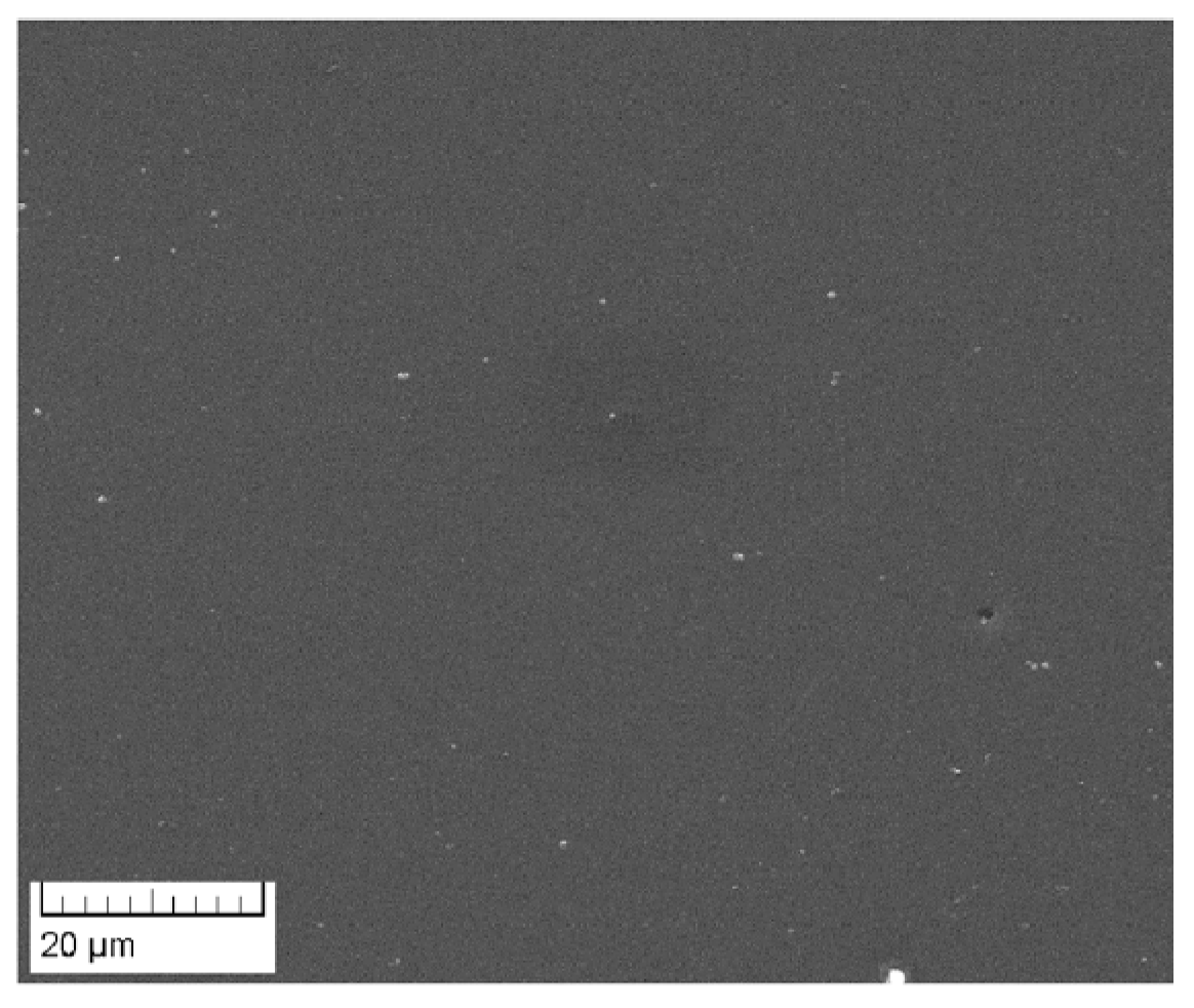
The relief of the newly formed surface repeats the surface morphology of the substrate, regardless of the deposition conditions. When applying tantalum to the titanium sublayer, an additional roughness smoothing of the surface is observed (Figure 3). However, at short distances, dotty deepening surface microdefects appear (Figure 4), resembling ion implantation [62], which correlate with a higher flow of spray substance reaching the surface of the substrate compared with longer distances.
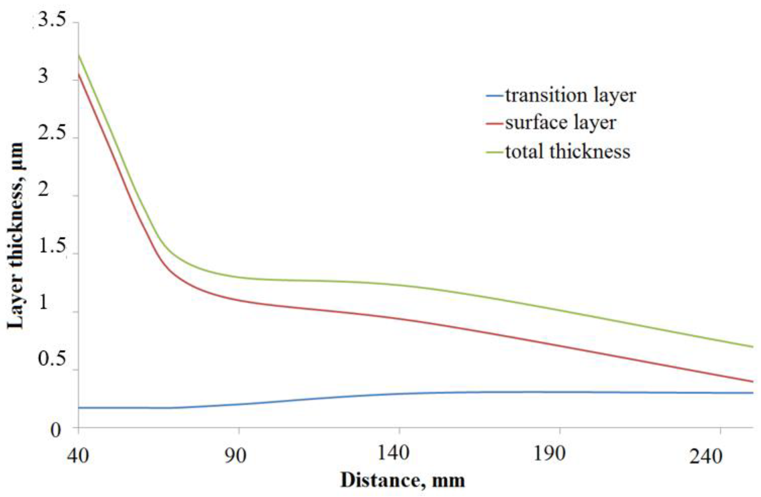
With an increase in the distance, other conditions being equal, on the one hand, the thickness of the deposited zones diminishes (Figure 5), since more of the sprayed substance diverge to the sides from the main sputtering axis without hitting the substrate; on the other hand, the transition zone thickness rises, which may be due to the higher flux density of the sprayed material particles at a smaller distances, faster and evenly settling on the interface and less penetrating into the base material. The summary layers thickness practically does not change at a distance of 80–150 mm and decreases at a greater distance. As the existence of a significant transition zone is a presumed cause for high adhesion of the newly deposited surface to the base material, and this surface must be adapted to the mechanical behavior of the substrate, and taking into account surface microdefects at short length between the substrate and the sputtered target, distances within 100–150 mm are more optimal.
With increasing deposition time an almost linear growth in the thickness of both the surface and transition layers is observed, and the transition zone formed approximately 2 times slower than the surface one. For example (Figure 6), under conditions of 865 mA and 400 V, deposition distance of 200 mm, the growth rate the tantalum surface layer was about 28 nm per minute, and the transition layer was about 15 nm per minute. However, there was a significant difference in that the transition zone stopped growing after about 300 nm, and it can be assumed that the transition layer is saturated. Thus, at a deposition time of 30 minutes, the maximum possible transition layer (0.3 μm) and a surface layer of about 0.9 μm were formed under the given conditions, which correspond to the previously selected optimal conditions when changing the distance. The pattern was preserved under all conditions and materials used.
At the beginning of the formation of the new surface zone, the particles of the deposited substance, overcoming the spraying distance, colliding with working gas atoms and ions, with each other and with the new surface of the substrate, do not end up in each surface section at the same time and at first interact with it randomly and irregularly Thereafter (with an increase in the spraying time, and hence the time of exposure to the surface), the particles kept colliding and mixing, trying to take an energetically more favorable state and position, leading to a more uniform distribution of the precipitated substance on the surface. The selected value of the operating pressure for the surface layer deposition of ≈ 0.4 Pa, according to the literature data, promotes the formation of strong films of a crystalline structure with low surface roughness and high density [55,58,59,63]. The continuous interaction of the mobilized particles of the target and the substrate contributes to the fact that, when the layer thickness reached 300 nm in this work, the islands were already smoothed out.
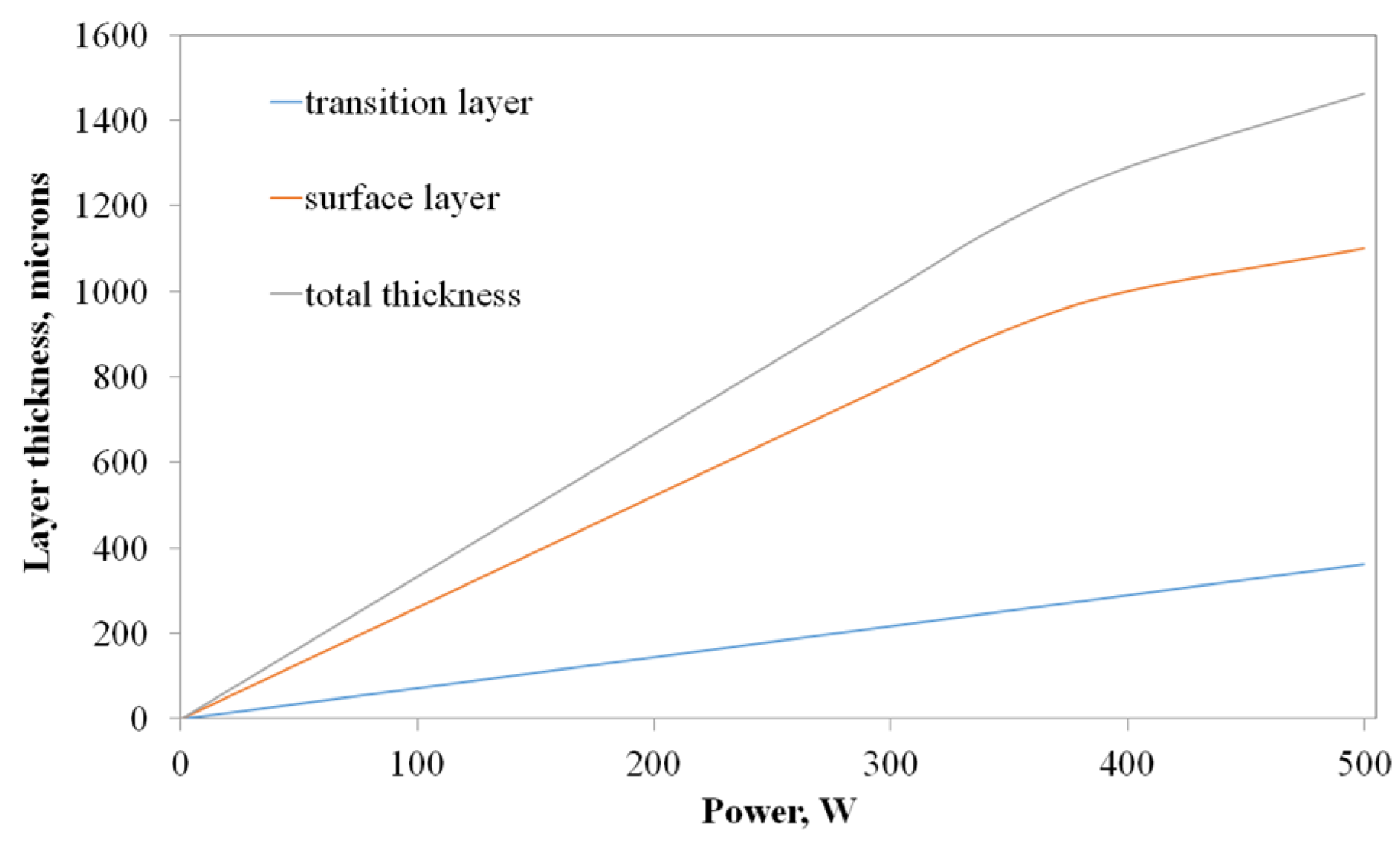
The total thickness value of the surface and transition layers increased almost linearly with increasing deposition power. Thus, when titanium was deposited on any substrate at the deposition distance 150 mm, for 30 min, in the deposition power range of 0–350 W, the average increase in the thickness of the surface layer was 2.61 nm/W, and the transition layer was 0.725 nm/W (Figure 7). An increase in their thickness may be associated with an increased target sputtering rate. The effect of a further increase in power (up to 500 W) was slightly less, which may be caused by the compaction of the near-surface zone and the reduction in the time for transition layer creation with an increase in the deposited material flux density and energy, but at the same time, the target consumption of the target and the possibility of contamination of the composite surface increased, including by-elements of the stainless steel vacuum chamber walls, which can be etched by high-energy particles; it is also possible to spray the newly formed surface with high-energy particles of the deposited flow.
It was noted that with equal sputtering–deposition parameters, the layer growth rates for tantalum and titanium are the same. For example, this is shown in Figure 1, where tantalum and titanium layers obtained with the same parameters are identical in thickness, which is in good agreement with the literature data, for example, with ref. [44].
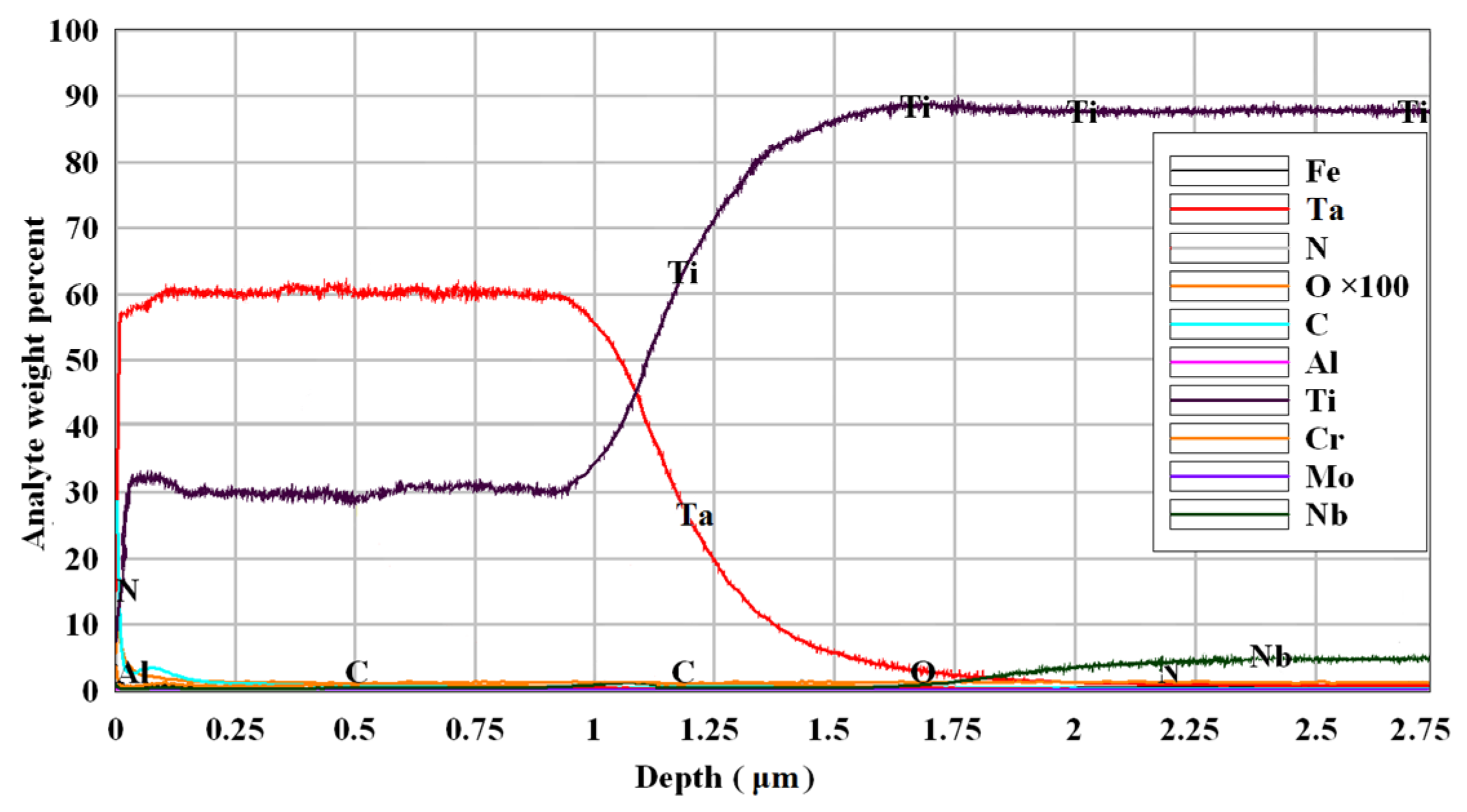
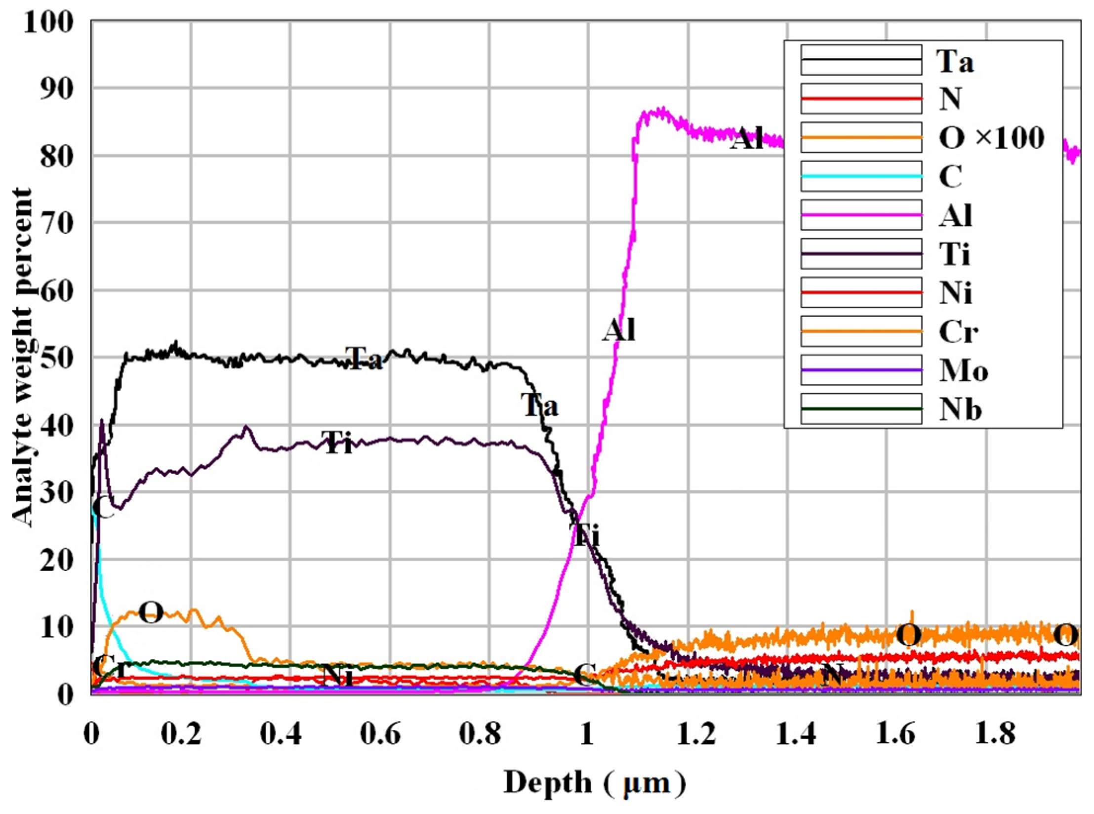
With the simultaneous deposition of tantalum and titanium, composite materials "oxy nitride layer (the area at the very boundary of the solid body with the surrounding gaseous medium, free from substrate elements, where the content of titanium or tantalum is not at a maximum, about 10 nm thick)—a surface layer of tantalum with titanium–a transition layer containing elements of the surface and the base–the base" were obtained (Figure 8, Figure 9 and Figure 10). The general regularity of the change in the in composition with depth of the obtained composites is approximately the same. Depending on the deposition parameters, regularities were obtained identical to the regularities of the formation of single layers of individual elements.
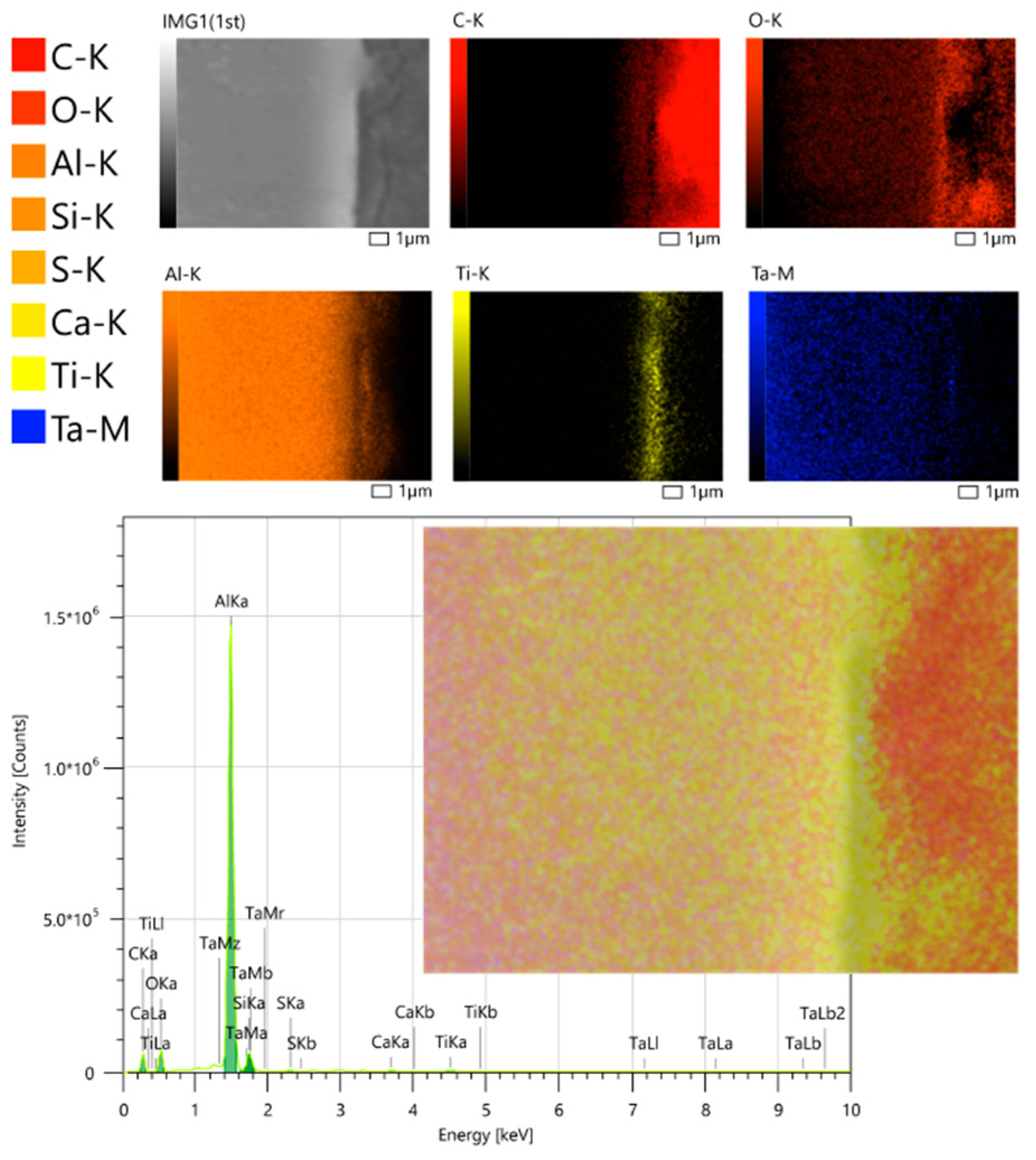
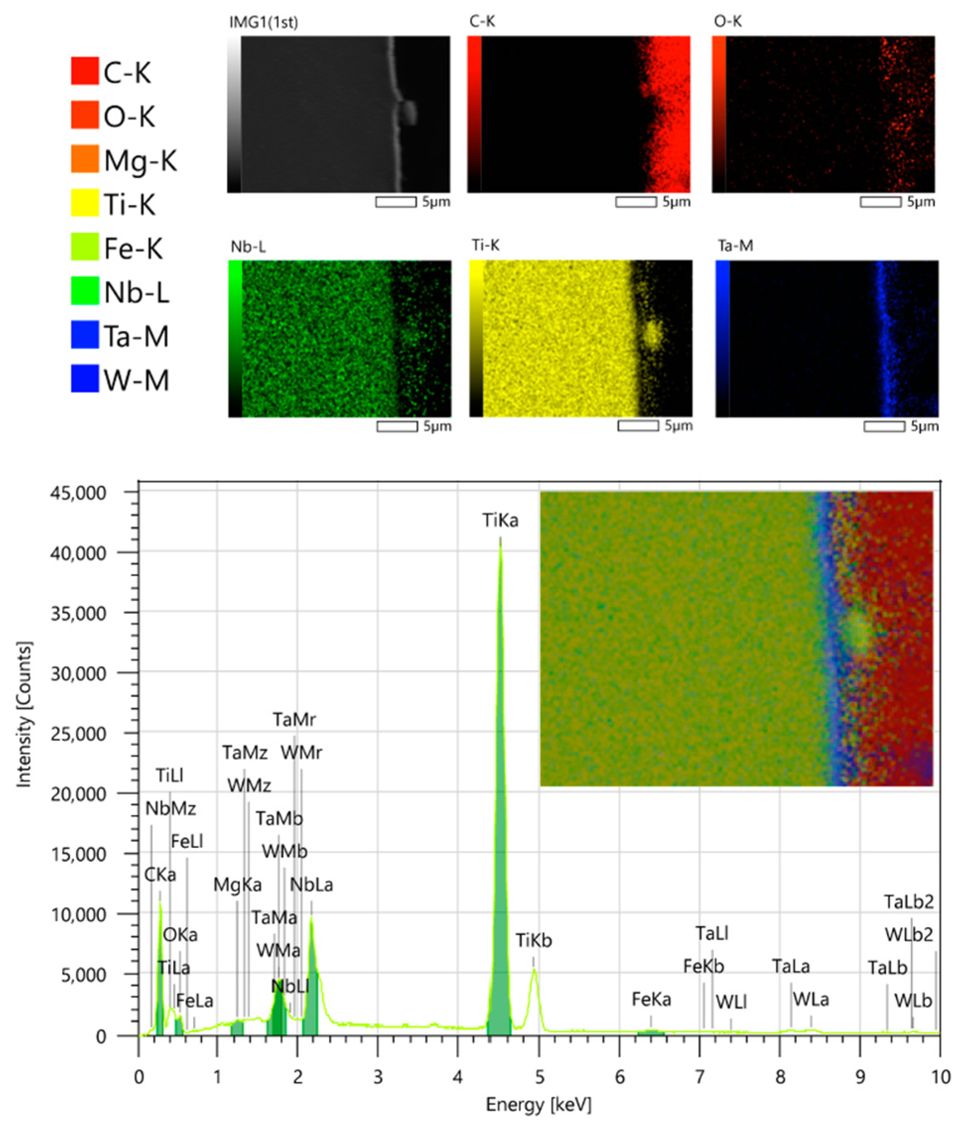
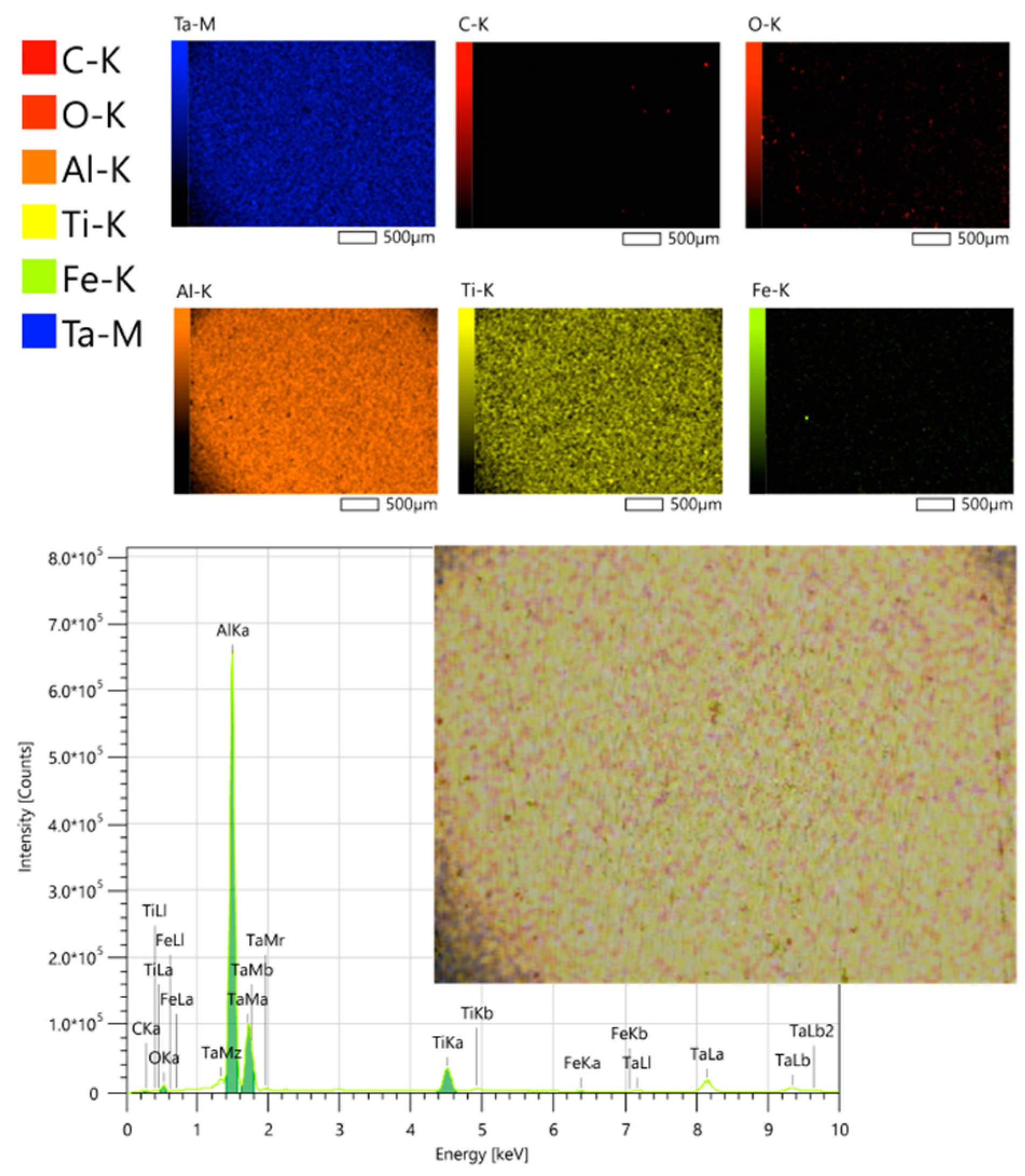
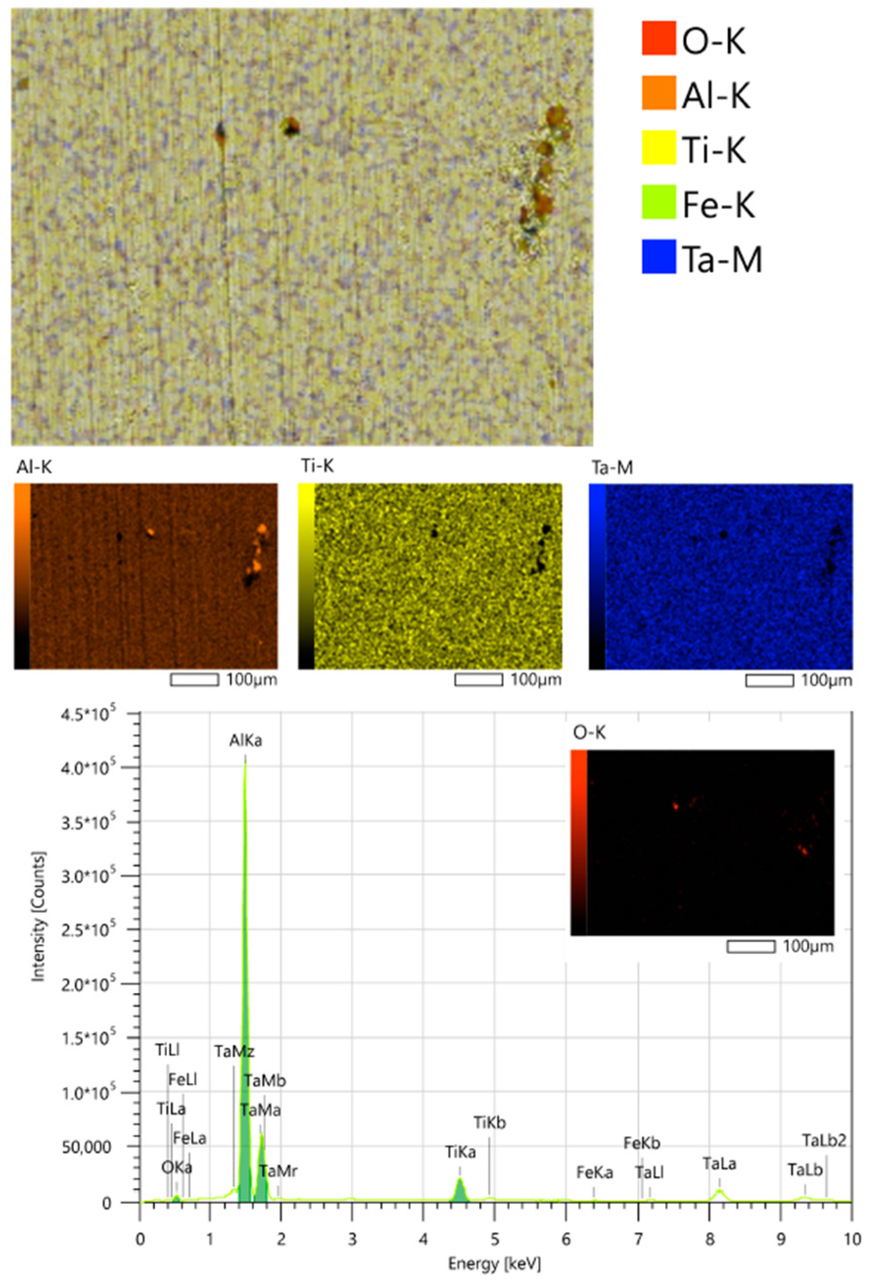
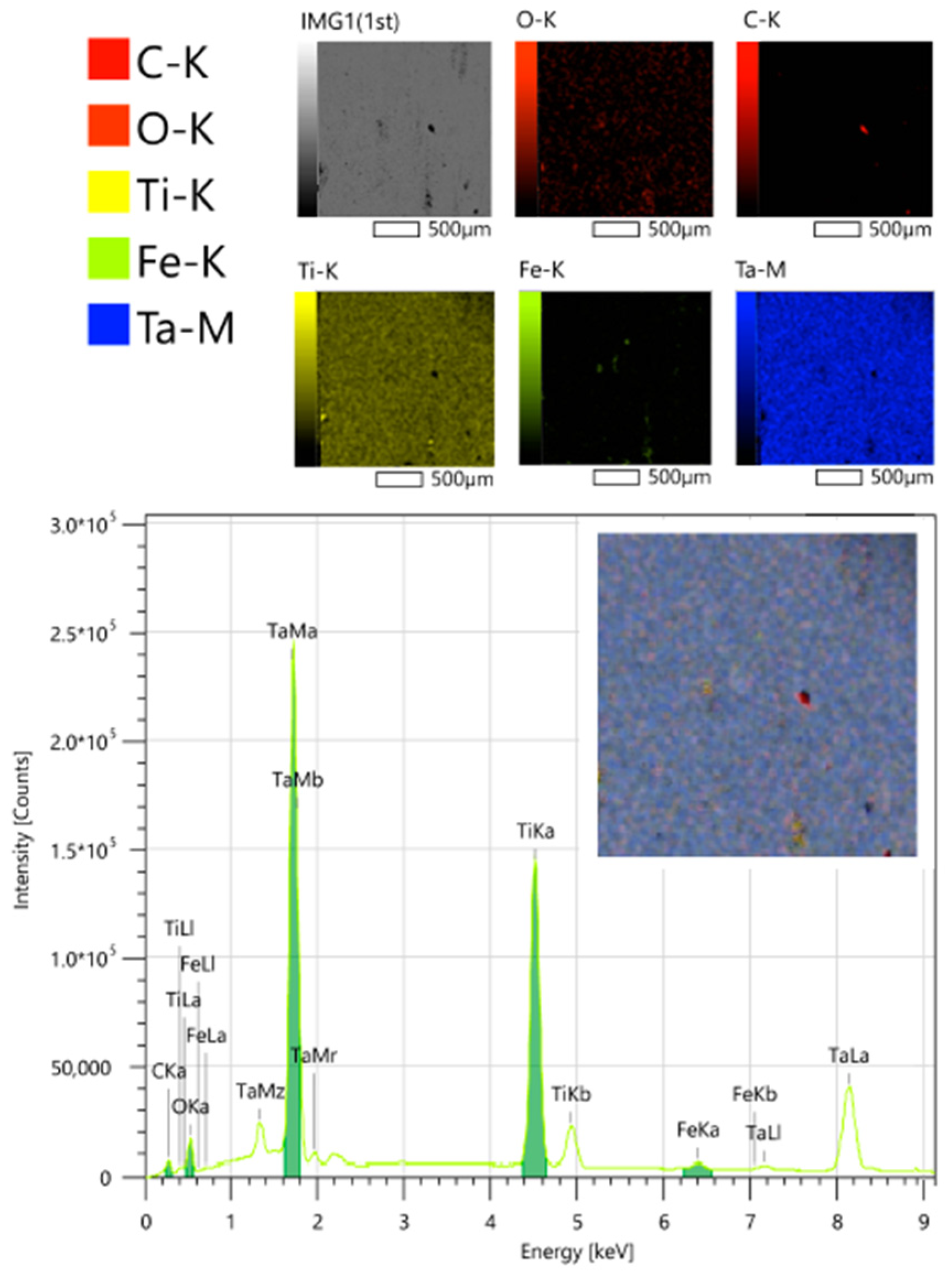
The results of element mapping in a transverse section (Figure 11, Figure 12 and Figure 13) are in good agreement with the layer-by-layer analysis of the chemical composition of the surface. The surface layer of the mixed composition clearly stands out on the substrate of both foreign material (aluminum) and titanium alloy. When mapping surface elements, a uniform distribution of deposited metals without the formation of clusters can be noted, and a visual decrease in the contribution of the substrate can be seen when the layer thickness increased from 0.4 to 0.9 µm (Figure 14, Figure 15 and Figure 16).
In the case of X-ray phase analysis of a titanium surface layer, regardless of its thickness, production parameters and the nature of the underlying substrate, only the beta phase (cubic crystal lattice) is observed, and this composition was not identical to the cast sputtered target phase composition (alpha). An example is shown in the Figure 17, the main peaks correspond to the phases: Ti—Im-3m: 39°26′, 83°31′; B-19 NiTi—21/m(11): 21°46′, 36°18′, 39°26′, 40°45′, 43°8′, 44°17′, 45°8′, 46°51′, 56°43′, 83°31′; R NiTi—P-3(147): 39°26′, 44°34′, 45°8′, 46°51′, 78°9′, 79°46′, 93°36′.
When creating thin tantalum films and layers, as noted in the literature, its formation in both beta and alpha states is possible [51,52,53,54,55,56,57,58,59,63,64,65,66,67,68,69,70,71,72,73]. At the same time, several theories have been developed for the formation of tantalum in one or another phase state, mainly related to temperature and pressure (which determine the motility and energy of atoms) and the substrate composition and surface condition. However, different authors often come to conflicting results.
According to our previous studies [74,75], regardless of the deposition conditions, the beta phase of tantalum is first formed, and alpha-tantalum is deposited on it (which is presumably due to the oxygen presence in the surface of all substrates), as in ref. [56], where, however, this was associated with a significant heating of the surface (more than 350 °C).
It was observed that tantalum in alpha state is created at temperature above 400 °C, which contributes to an increase in the mobility of the deposited atoms: either during initially heating of the substrate or annealing following deposition (when the obtained beta phase turns into alpha Ta) [56,63,67]. However, at the temperature range from 400 to 500 °C the beta tantalum was also obtained [63,67], while α was formed even without heating [54,57]. It was indicated that with increasing temperature, the grain size, the amount of surface layer impurities, and its amorphism decrease.
A high oxygen content in the working atmosphere in [58] leads to the rapid creation of oxides causing the creation of a beta tantalum layer, while in ref. [57] the oxygen environment did not interfere with the creation tantalum alpha phase. When deposited on glass and silicon substrates, a pressure of 0.5 ± 0.7 Pa in Refs [55,58,59] led to the formation of α-Ta and at lower or higher pressure, β-Ta; however, in ref. [57], the α phase was already formed at 0.28 Pa, and in [59], the alpha tantalum creation also occurred at pressures of 0.3 and 1.4 Pa.
Being the zone of nucleation of a new surface, the base substrate surface determines the new structure creation nature. It has been noted that beta tantalum is formed on amorphous surfaces containing carbon or oxygen (the inartificial state of glass or titanium and aluminum in an oxygen atmosphere), whereas, for example, on titanium without natural oxide, on previously deposited α-Ta or TaN alpha tantalum is formed [52,54,56,59]. Additionally, it was pointed out that (110) phase is the lowest energy lattice for bcc materials and causes the formation of the same structure on itself, and α-Ta (110) is the thermodynamically most stable phase.
In an oxygen-free environment, beta and alpha titanium formed, respectively, and on glass and silicon, α-Ta formed [54]. Beta titanium and alpha tantalum have a similar type of crystal lattice (110); the α-Ti lattice parameters match with the parameters of the hexagonal lattice composed of atoms of the nearest α-Ta planes. In these two cases, titanium grains can serve as the nucleation core for Ta crystallites. The amorphous oxide layer differs too much in structure from the α-Ta crystal lattice and this difference leads to the formation of β-Ta.
Thus, in this work, we expected to see a modification of tantalum.
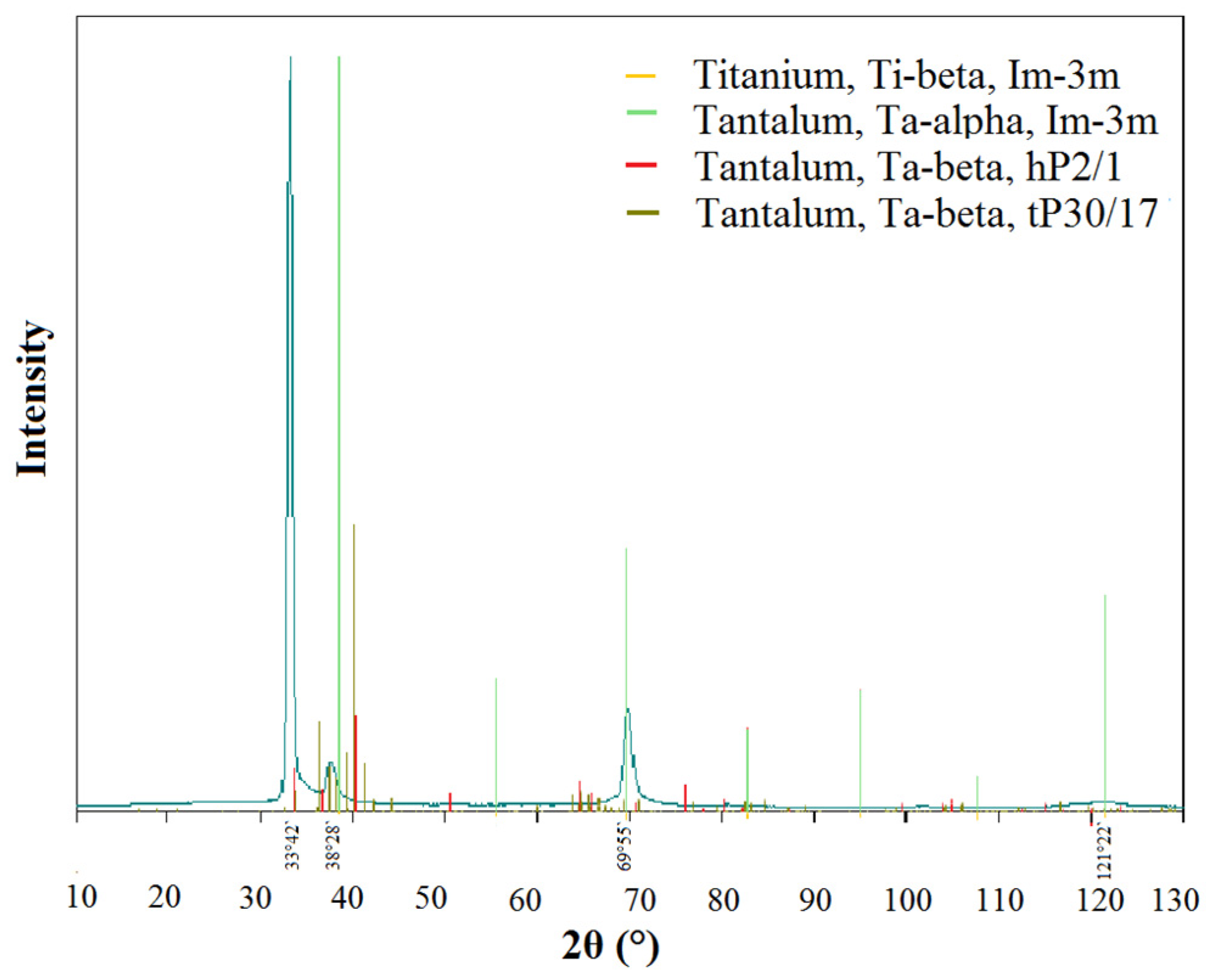
In this work, if a Ta surface layer deposited on titanium, after prolonged ion etching (i.e. without an oxygen-containing surface) and without it, a lot of alpha and beta tantalum peaks are recorded, which corresponds to different crystal orientations: beta (002, 410, 202, 004, 513, 333, 404, etc.), alpha (110, 211, and 220), i.e., a strongly textured structure is formed, regardless of the substrate surface. Example is shown in Figure 18, the main peaks correspond to the phases: Ti-beta, Im-3m: 38°28′, 69°55′, 121°22′; Ta-alpha, Im-3m: 38°28′, 69°55′, 121°22′; Ta- beta, hP2/1: 33°42′, 69°55′, 121°22′; Ta-beta, tP30/17: 33°42′, 38°28′, 69°55′, 121°22′).
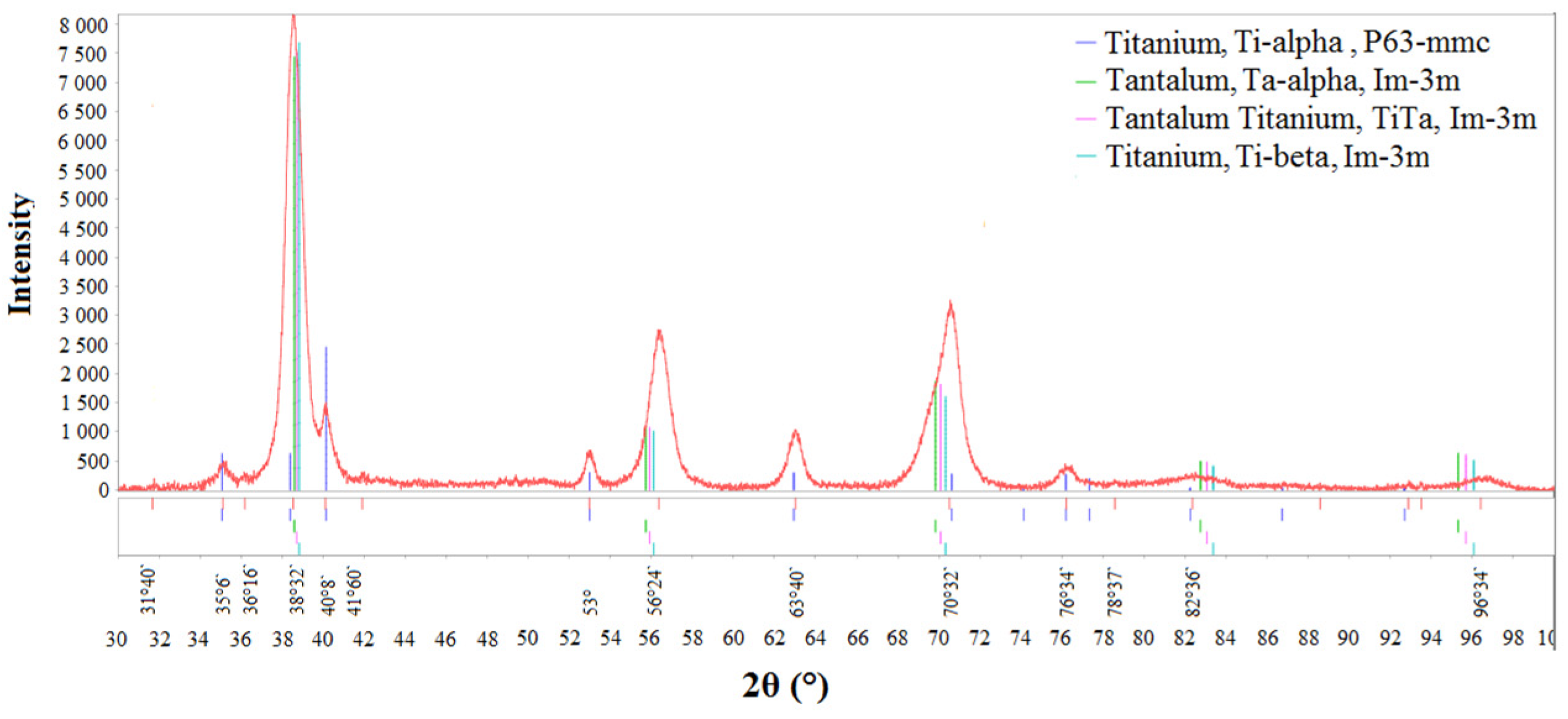
X-ray phase studies suggest that even at small thicknesses of the surface layer, the co-deposition of tantalum and titanium contributes to the formation of a single tantalum phase, alpha. In Figure 19 the main peak on the X-ray corresponds to the substrate due to averaging over the entire depth of analysis, corresponding to a mixture of alpha titanium (hexagonal lattice) and beta, the surface peaks correspond to the TiTa (cubic), beta Ti (cubic, typical for magnetron deposition according to previous studies) and alpha Ta (cubic) (i.e., the main angles in the figure correspond to Ti-alpha, P63-mmc: 35°6′, 38°32′, 40°8′, 53°, 63°40′, 70°32′, 76°34′, 82°36′, Ta-alpha, Im-3m: 38°32′, 56°24′, 70°32′, 82°36′, 96°34′, TiTa, Im-3m: 35°6′, 36°16′, 38°32′, 56°24′, 70°32′, 82°36′, 96°34′, Ti-beta, Im-3m: 38°32′, 56°24′, 70°32′, 82°36′, 96°34′), while, as previously discussed, beta-Ti and alpha-Ta have a similar type of crystal lattice (110), and the parameters of the alpha-Ti lattice coincide with the parameters of the hexagonal lattice composed of atoms of the nearest alpha-Ta planes, which determine the only possible option for the development of tantalum crystallite. If the deposition occurs on a substrate of a different nature (Figure 20, on aluminum), we also observe the main peak from the substrate, and, on the surface, a mixture of alpha tantalum, beta titanium and TiTa (the main angles correspond to Al, Fm-3m: 38°28′, 44°38′, 65°12′, 78°, TiTa, Im-3m: 38°28′, 56°6′, 70°, 82°34′, 96°19′, Ta-alpha, Im-3m: 38°28′, 56°6′, 70°, 82°34′, 96°19′, and Ti-beta, Im-3m: 38°28′, 56°6′, 70°, 82°34′, 96°19′).
Carrying out irradiation of the substrate surface with argon ions before layer deposition not only to cleaning the surface from impurities, but also to fine polishing and activation of this surface, which ensures the formation of a stable transition layer.
The results of studying the mechanical properties of composites with titanium and tantalum–titanium surface layers and a titanium alloy base are shown in Table 1.
Based on the data obtained, it can be concluded that the elongation increases as the surface layers are deposited and thickened by the magnetron deposition method, while the strength and Young’s modulus decrease slightly, and the additional deposition of tantalum increases all indicators.

4. Conclusions

The patterns of formation of layered composite materials with a surface metal layer of a bicomponent composition (Ta/Ti) using a complex vacuum technology, including magnetron sputtering, with varying process conditions, including options for supplying elemental fluxes (in series and in parallel, from one source when using a target of mixed composition) were studied.
An almost linear increase in the thickness of both the surface and transition layers was observed with increasing deposition time, and the transition zone was formed approximately two times slower than the surface one and stopped growing after reaching about 300 nm. The total thickness of the surface and transition layers increased almost linearly with increasing power, but after some power critical value the growth rate decreased. With equal sputtering–deposition parameters, the layer growth rates for tantalum and titanium were the same.
In the case of a sample with a Ta surface layer deposited on titanium, a strongly textured mixture of alpha and beta phases was observed, which was insignificantly related to the initial structure of the substrate and the underlying layer. However, even at small thicknesses of the surface layer, the joint deposition of tantalum and titanium contributed to the formation of a single tantalum phase, alpha.
The elongation increased as the surface layers were deposited and thickened, while the strength and Young’s modulus decreased slightly, and the additional deposition of tantalum on titanium improved everything.
The results of the works carried out using vacuum technologies and modern methods for studying materials have prospects for use in various fields of science and technology (medicine, electronics, optics, structural materials, etc.).

Author Contributions

Conceptualization, M.A.S. (Maria Andreevna Sudarchikova); funding acquisition, E.O.N.; investigation, E.O.N., K.V.S., K.Y.D., A.B.M., M.A.K., A.S.B. and S.V.K.; methodology, A.G.K., E.O.N.; project administration, M.A.S. (Mikhail Anatolyevich Sevostyanov); supervision, M.A.S. (Mikhail Anatolyevich Sevostyanov); validation, S.V.K.; visualization, K.V.S.; writing—original draft, E.O.N.; writing—review and editing, E.O.N. and M.A.S. (Maria Andreevna Sudarchikova). All authors have read and agreed to the published version of the manuscript.

Funding

This research was funded by Russian Science Foundation, grant number 21-79-10256.

Institutional Review Board Statement

Not applicable.

Informed Consent Statement

Not applicable.

Data Availability Statement

Not applicable.

Conflicts of Interest

The authors declare no conflict of interest.

References

  1. Wiatrowski, A.; Mazur, M.; Obstarczyk, A.; Wojcieszak, D.; Kaczmarek, D.; Morgiel, J.; Gibson, D. Comparison of the Physicochemical Properties of TiO2 Thin Films Obtained by Magnetron Sputtering with Continuous and Pulsed Gas Flow. Coatings 2018, 8, 412. [Google Scholar] [CrossRef] [Green Version]
  2. El-Fattah, H.A.A.; El-Mahallawi, I.S.; Shazly, M.H.; Khalifa, W.A. Optical Properties and Microstructure of TiNxOy and TiN Thin Films before and after Annealing at Different Conditions. Coatings 2019, 9, 22. [Google Scholar] [CrossRef] [Green Version]
  3. Hu, Y.; Rasadujjaman, M.; Wang, Y.; Zhang, J.; Yan, J.; Baklanov, M. Study on the Electrical, Structural, Chemical and Optical Properties of PVD Ta(N) Films Deposited with Different N2 Flow Rates. Coatings 2021, 11, 937. [Google Scholar] [CrossRef]
  4. Dongquoc, V.; Seo, D.-B.; Anh, C.V.; Lee, J.-H.; Park, J.-H.; Kim, E.-T. Controlled Surface Morphology and Electrical Properties of Sputtered Titanium Nitride Thin Film for Metal–Insulator–Metal Structures. Appl. Sci. 2022, 12, 10415. [Google Scholar] [CrossRef]
  5. Korotkova, K.; Bainov, D.; Smirnov, S.; Yunusov, I.; Zhidik, Y. Electrical Conductivity and Optical Properties of Nanoscale Titanium Films on Sapphire for Localized Plasmon Resonance-Based Sensors. Coatings 2020, 10, 1165. [Google Scholar] [CrossRef]
  6. Zaman, A.; Meletis, E.I. Microstructure and Mechanical Properties of TaN Thin Films Prepared by Reactive Magnetron Sputtering. Coatings 2017, 7, 209. [Google Scholar] [CrossRef] [Green Version]
  7. Qiao, Z.; Li, X.; Lv, Y.; Xie, Y.; Hu, Y.; Wang, J.; Li, H.; Wang, S. Depositing a Titanium Coating on the Lithium Neutron Production Target by Magnetron Sputtering Technology. Materials 2021, 14, 1873. [Google Scholar] [CrossRef] [PubMed]
  8. Kaltschmidt, B.P.; Asghari, E.; Kiel, A.; Cremer, J.; Anselmetti, D.; Kaltschmidt, C.; Kaltschmidt, B.; Hütten, A. Magnetron Sputtering of Transition Metals as an Alternative Production Means for Antibacterial Surfaces. Microorganisms 2022, 10, 1843. [Google Scholar] [CrossRef]
  9. de Monteynard, A.; Luo, H.; Chehimi, M.; Ghanbaja, J.; Achache, S.; François, M.; Billard, A.; Sanchette, F. The Structure, Morphology, and Mechanical Properties of Ta-Hf-C Coatings Deposited by Pulsed Direct Current Reactive Magnetron Sputtering. Coatings 2020, 10, 212. [Google Scholar] [CrossRef] [Green Version]
  10. Rivera-Tello, C.D.; Broitman, E.; Flores-Ruiz, F.J.; Perez-Alvarez, J.; Flores-Jiménez, M.; Jiménez, O.; Flores, M. Micro and Macro-Tribology Behavior of a Hierarchical Architecture of a Multilayer TaN/Ta Hard Coating. Coatings 2020, 10, 263. [Google Scholar] [CrossRef]
  11. Farahani, N.; Kelly, P.J.; West, G.; Hill, C.; Vishnyakov, V. Photocatalytic Activity of Reactively Sputtered Titania Coatings Deposited Using a Full Face Erosion Magnetron. Coatings 2013, 3, 177–193. [Google Scholar] [CrossRef] [Green Version]
  12. Wang, Y.-H.; Rahman, K.H.; Wu, C.-C.; Chen, K.-C. A Review on the Pathways of the Improved Structural Characteristics and Photocatalytic Performance of Titanium Dioxide (TiO2) Thin Films Fabricated by the Magnetron-Sputtering Technique. Catalysts 2020, 10, 598. [Google Scholar] [CrossRef]
  13. Kelly, P.J.; West, G.T.; Ratova, M.; Fisher, L.; Ostovarpour, S.; Verran, J. Structural Formation and Photocatalytic Activity of Magnetron Sputtered Titania and Doped-Titania Coatings. Molecules 2014, 19, 16327–16348. [Google Scholar] [CrossRef] [PubMed]
  14. Kim, J.-Y.; Park, J.-B. Various Coated Barrier Membranes for Better Guided Bone Regeneration: A Review. Coatings 2022, 12, 1059. [Google Scholar] [CrossRef]
  15. García, E.; Flores, M.; Rodríguez, E.; Rivera, L.P.; Camps, E.; Muhl, S. Tribological, Tribocorrosion and Wear Mechanism Studies of TaZrN Coatings Deposited by Magnetron Sputtering on TiAlV Alloy. Coatings 2018, 8, 295. [Google Scholar] [CrossRef] [Green Version]
  16. Alvarez, R.; Muñoz-Piña, S.; González, M.U.; Izquierdo-Barba, I.; Fernández-Martínez, I.; Rico, V.; Arcos, D.; García-Valenzuela, A.; Palmero, A.; Vallet-Regi, M.; et al. Antibacterial Nanostructured Ti Coatings by Magnetron Sputtering: From Laboratory Scales to Industrial Reactors. Nanomaterials 2019, 9, 1217. [Google Scholar] [CrossRef] [Green Version]
  17. Yelkarasi, C.; Recek, N.; Kazmanli, K.; Kovač, J.; Mozetič, M.; Urgen, M.; Junkar, I. Biocompatibility and Mechanical Stability of Nanopatterned Titanium Films on Stainless Steel Vascular Stents. Int. J. Mol. Sci. 2022, 23, 4595. [Google Scholar] [CrossRef] [PubMed]
  18. Mina-Aponzá, S.; Castro-Narváez, S.; Caicedo-Bejarano, L.; Bermeo-Acosta, F. Study of Titanium–Silver Monolayer and Multilayer Films for Protective Applications in Biomedical Devices. Molecules 2021, 26, 4813. [Google Scholar] [CrossRef] [PubMed]
  19. Ding, Z.; Zhou, Q.; Wang, Y.; Ding, Z.; Tang, Y.; He, Q. Microstructure and properties of monolayer, bilayer and multilayer Ta2O5-based coatings on biomedical Ti-6Al-4V alloy by magnetron sputtering. Ceram. Int. 2020, 47, 1133–1144. [Google Scholar] [CrossRef]
  20. Zhang, M.; Ma, Y.; Gao, J.; Hei, H.; Jia, W.; Bai, J.; Liu, Z.; Huang, X.; Xue, Y.; Yu, S.; et al. Mechanical, Electrochemical, and Osteoblastic Properties of Gradient Tantalum Coatings on Ti6Al4V Prepared by Plasma Alloying Technique. Coatings 2021, 11, 631. [Google Scholar] [CrossRef]
  21. Rodrigues, M.M.; Fontoura, C.P.; Maddalozzo, A.E.D.; Leidens, L.M.; Quevedo, H.G.; Souza, K.D.S.; Crespo, J.D.S.; Michels, A.F.; Figueroa, C.A.; Aguzzoli, C. Ti, Zr and Ta coated UHMWPE aiming surface improvement for biomedical purposes. Compos. Part B: Eng. 2020, 189, 107909. [Google Scholar] [CrossRef]
  22. Ji, P.; Liu, S.; Deng, H.; Ren, H.; Zhang, J.; Sun, T.; Xu, K.; Shi, C. Effect of magnetron-sputtered monolayer Ta and multilayer Ti-Zr-Ta and Zr-Ti-Ta coatings on the surface properties of biomedical Ti-6Al-4V alloy. Mater. Lett. 2022, 322. [Google Scholar] [CrossRef]
  23. Baigonakova, G.; Marchenko, E.; Yasenchuk, Y.; Kokorev, O.; Vorozhtsov, A.; Kulbakin, D. Microstructural characterization, wettability and cytocompatibility of gradient coatings synthesized by gas nitriding of three-layer Ti/Ni/Ti nanolaminates magnetron sputtered on the TiNi substrate. Surf. Coatings Technol. 2022, 436. [Google Scholar] [CrossRef]
  24. Lenis, J.; Rico, P.; Ribelles, J.G.; Pacha-Olivenza, M.; González-Martín, M.; Bolívar, F. Structure, morphology, adhesion and in vitro biological evaluation of antibacterial multi-layer HA-Ag/SiO2/TiN/Ti coatings obtained by RF magnetron sputtering for biomedical applications. Mater. Sci. Eng. C 2020, 116, 111268. [Google Scholar] [CrossRef] [PubMed]
  25. Lenis, J.; Bejarano, G.; Rico, P.; Ribelles, J.G.; Bolívar, F. Development of multilayer Hydroxyapatite - Ag/TiN-Ti coatings deposited by radio frequency magnetron sputtering with potential application in the biomedical field. Surf. Coatings Technol. 2019, 377, 124856. [Google Scholar] [CrossRef]
  26. López-Huerta, F.; Cervantes, B.; González, O.; Hernández-Torres, J.; García-González, L.; Vega, R.; Herrera-May, A.L.; Soto, E. Biocompatibility and Surface Properties of TiO2 Thin Films Deposited by DC Magnetron Sputtering. Materials 2014, 7, 4105–4117. [Google Scholar] [CrossRef] [PubMed] [Green Version]
  27. Marchenko, E.; Baigonakova, G.; Kokorev, O.; Yasenchuk, Y.; Vorozhtsov, A. Biocompatibility Assessment of Coatings Obtained in Argon and Nitrogen Atmospheres for TiNi Materials. Metals 2022, 12, 1603. [Google Scholar] [CrossRef]
  28. Domínguez-Crespo, M.; Torres-Huerta, A.; Rodríguez, E.; González-Hernández, A.; Brachetti-Sibaja, S.; Dorantes-Rosales, H.; López-Oyama, A. Effect of deposition parameters on structural, mechanical and electrochemical properties in Ti/TiN thin films on AISI 316L substrates produced by r. f. magnetron sputtering. J. Alloy. Compd. 2018, 746, 688–698. [Google Scholar] [CrossRef]
  29. Akimchenko, I.O.; Rutkowski, S.; Tran, T.-H.; Dubinenko, G.E.; Petrov, V.I.; Kozelskaya, A.I.; Tverdokhlebov, S.I. Polyether Ether Ketone Coated with Ultra-Thin Films of Titanium Oxide and Zirconium Oxide Fabricated by DC Magnetron Sputtering for Biomedical Application. Materials 2022, 15, 8029. [Google Scholar] [CrossRef] [PubMed]
  30. Subramanian, B.; Muraleedharan, C.; Ananthakumar, R.; Jayachandran, M. A comparative study of titanium nitride (TiN), titanium oxy nitride (TiON) and titanium aluminum nitride (TiAlN), as surface coatings for bio implants. Surf. Coatings Technol. 2011, 205, 5014–5020. [Google Scholar] [CrossRef]
  31. González-Hernández, A.; Aperador, W.; Flores, M.; Onofre-Bustamante, E.; Bermea, J.E.; Bautista-García, R.; Gamboa-Soto, F. Influence of Deposition Parameters on Structural and Electrochemical Properties of Ti/Ti2N Films Deposited by RF-Magnetron Sputtering. Metals 2022, 12, 1237. [Google Scholar] [CrossRef]
  32. Stolin, A.M.; Bazhin, P. Manufacture of multipurpose composite and ceramic materials in the combustion regime and high-temperature deformation (SHS extrusion). Theor. Found. Chem. Eng. 2014, 48, 751–763. [Google Scholar] [CrossRef]
  33. Bazhin, P.; Stolin, A.M.; Alymov, M.I. Preparation of nanostructured composite ceramic materials and products under conditions of a combination of combustion and high-temperature deformation (SHS extrusion). Nanotechnologies Russ. 2014, 9, 583–600. [Google Scholar] [CrossRef]
  34. Krivoshapkin, P.; Mikhaylov, V.; Krivoshapkina, E.; Zaikovskii, V.; Melgunov, M.; Stalugin, V. Mesoporous Fe–alumina films prepared via sol–gel route. Microporous Mesoporous Mater. 2015, 204, 276–281. [Google Scholar] [CrossRef]
  35. Kononova, S.V.; Korytkova, E.N.; Maslennikova, T.; Romashkova, K.A.; Kruchinina, E.V.; Potokin, I.L.; Gusarov, V. Polymer-inorganic nanocomposites based on aromatic polyamidoimides effective in the processes of liquids separation. Russ. J. Gen. Chem. 2010, 80, 1136–1142. [Google Scholar] [CrossRef]
  36. Fattah-Alhosseini, A.; Elmkhah, H.; Ansari, G.; Attarzadeh, F.; Imantalab, O. A comparison of electrochemical behavior of coated nanostructured Ta on Ti substrate with pure uncoated Ta in Ringer’s physiological solution. J. Alloy. Compd. 2018, 739, 918–925. [Google Scholar] [CrossRef]
  37. Seidl, W.; Bartosik, M.; Kolozsvári, S.; Bolvardi, H.; Mayrhofer, P. Improved mechanical properties, thermal stabilities, and oxidation resistance of arc evaporated Ti-Al-N coatings through alloying with Ta. Surf. Coatings Technol. 2018, 344, 244–249. [Google Scholar] [CrossRef]
  38. Sevost’Yanov, M.A.; Nasakina, E.O.; Baikin, A.S.; Sergienko, K.V.; Konushkin, S.V.; Kaplan, M.A.; Seregin, A.V.; Leonov, A.V.; Kozlov, V.A.; Shkirin, A.V.; et al. Biocompatibility of new materials based on nano-structured nitinol with titanium and tantalum composite surface layers: Experimental analysis in vitro and in vivo. J. Mater. Sci. Mater. Med. 2018, 29, 33. [Google Scholar] [CrossRef]
  39. Li, P.; Zhang, X.; Xu, R.; Wang, W.; Liu, X.; Yeung, K.W.K.; Chu, P.K. Electrochemically deposited chitosan/Ag complex coatings on biomedical NiTi alloy for antibacterial application. Surf. Coat. Technol. 2013, 232, 370–375. [Google Scholar] [CrossRef]
  40. Cheng, Y.; Cai, W.; Li, H.T.; Zheng, Y.F. Surface modification of NiTi alloy with tantalum to improve its biocompatibility and radiopacity. J. Mater. Sci. 2006, 41, 4961–4964. [Google Scholar] [CrossRef]
  41. Lee, D.-W.; Kim, Y.-N.; Cho, M.-Y.; Ko, P.-J.; Lee, D.; Koo, S.-M.; Moon, K.-S.; Oh, J.-M. Reliability and characteristics of magnetron sputter deposited tantalum nitride for thin film resistors. Thin Solid Films 2018, 660, 688–694. [Google Scholar] [CrossRef]
  42. Siddiqui, J.; Hussain, T.; Ahmad, R.; Umar, Z.A. On the structural, morphological and electrical properties of tantalum oxy nitride thin films by varying oxygen percentage in reactive gases plasma. Chin. J. Phys. 2017, 55, 1412–1422. [Google Scholar] [CrossRef]
  43. Kumar, M.; Kumari, N.; Kumar, V.P.; Karar, V.; Sharma, A.L. Determination of optical constants of tantalum oxide thin film deposited by electron beam evaporation. Mater. Today: Proc. 2018, 5, 3764–3769. [Google Scholar] [CrossRef]
  44. Cristea, D.; Velicu, I.-L.; Cunha, L.; Barradas, N.; Alves, E.; Craciun, V. Tantalum-Titanium Oxynitride Thin Films Deposited by DC Reactive Magnetron Co-Sputtering: Mechanical, Optical, and Electrical Characterization. Coatings 2021, 12, 36. [Google Scholar] [CrossRef]
  45. Ormanova, M.; Dechev, D.; Ivanov, N.; Mihai, G.; Gospodinov, M.; Valkov, S.; Enachescu, M. Synthesis and Characterization of Ti-Ta-Shape Memory Surface Alloys Formed by the Electron-Beam Additive Technique. Coatings 2022, 12, 678. [Google Scholar] [CrossRef]
  46. Tu, R.; Min, R.; Yang, M.; Yuan, Y.; Zheng, L.; Li, Q.; Ji, B.; Zhang, S.; Yang, M.; Shi, J. Overcoming the Dilemma between Low Electrical Resistance and High Corrosion Resistance Using a Ta/(Ta,Ti)N/TiN/Ti Multilayer for Proton Exchange Membrane Fuel Cells. Coatings 2022, 12, 689. [Google Scholar] [CrossRef]
  47. Guo, D.; Zhang, S.; Huang, T.; Wu, S.; Ma, X.; Guo, F. Corrosion Properties of DLC Film in Weak Acid and Alkali Solutions. Coatings 2022, 12, 1776. [Google Scholar] [CrossRef]
  48. Bunshah, R.F. Deposition Technologies for Films and Coating; Noyes Publikations: Park Ridge, IL, USA, 1982; p. 489 p. [Google Scholar]
  49. Kulczyk-Malecka, J.; Kelly, P.J.; West, G.; Clarke, G.C.; Ridealgh, J.A. Characterisation Studies of the Structure and Properties of As-Deposited and Annealed Pulsed Magnetron Sputtered Titania Coatings. Coatings 2013, 3, 166–176. [Google Scholar] [CrossRef]
  50. Al-Masha’Al, A.; Bunting, A.; Cheung, R. Evaluation of residual stress in sputtered tantalum thin-film. Appl. Surf. Sci. 2016, 371, 571–575. [Google Scholar] [CrossRef] [Green Version]
  51. Zhou, Y.M.; Xie, Z.; Xiao, H.N.; Hu, P.F.; He, J. Effects of deposition parameters on tantalum films deposited by direct current magnetron sputtering. J. Vac. Sci. Technol. A: Vacuum, Surfaces, Films 2009, 27, 109–113. [Google Scholar] [CrossRef]
  52. Bernoulli, D.; Müller, U.; Schwarzenberger, M.; Hauert, R.; Spolenak, R. Magnetron sputter deposited tantalum and tantalum nitride thin films: An analysis of phase, hardness and composition. Thin Solid Films 2013, 548, 157–161. [Google Scholar] [CrossRef]
  53. Zhou, Y.; Xie, Z.; Xiao, H.; Hu, P.; He, J. Effects of deposition parameters on tantalum films deposited by direct current magnetron sputtering in Ar–O2 mixture. Appl. Surf. Sci. 2011, 258, 1699–1703. [Google Scholar] [CrossRef]
  54. Zhou, Y.; Xie, Z.; Ma, Y.; Xia, F.; Feng, S. Growth and characterization of Ta/Ti bi-layer films on glass and Si (111) substrates by direct current magnetron sputtering. Appl. Surf. Sci. 2012, 258, 7314–7321. [Google Scholar] [CrossRef]
  55. Navid, A.; Chason, E.; Hodge, A. Evaluation of stress during and after sputter deposition of Cu and Ta films. Surf. Coatings Technol. 2010, 205, 2355–2361. [Google Scholar] [CrossRef]
  56. Myers, S.; Lin, J.; Souza, R.; Sproul, W.D.; Moore, J.J. The β to α phase transition of tantalum coatings deposited by modulated pulsed power magnetron sputtering. Surf. Coatings Technol. 2012, 214, 38–45. [Google Scholar] [CrossRef]
  57. Cacucci, A.; Loffredo, S.; Potin, V.; Imhoff, L.; Martin, N. Interdependence of structural and electrical properties in tantalum/tantalum oxide multilayers. Surf. Coatings Technol. 2012, 227, 38–41. [Google Scholar] [CrossRef] [Green Version]
  58. Navid, A.; Hodge, A. Nanostructured alpha and beta tantalum formation—Relationship between plasma parameters and microstructure. Mater. Sci. Eng. A 2012, 536, 49–56. [Google Scholar] [CrossRef]
  59. Navid, A.; Hodge, A. Controllable residual stresses in sputtered nanostructured alpha-tantalum. Scr. Mater. 2010, 63, 867–870. [Google Scholar] [CrossRef]
  60. Zabolotnyi, V.T. Ion Intermixing in Solids; MGIEM (TU): Moscow, Russian, 1997; p. 62 p. [Google Scholar]
  61. Kuz’michev, A.I. Magnetron Spattering Systems. Book 1. Introduction Into Physics And Technique Of Magnetron Scattering; Avers: Kiev, Ukraine, 2008; p. 244 p. [Google Scholar]
  62. Poate, J.M.; Foti, G.; Jacobson, D.C. Surface Modification and Alloying by Laser; Ion and Electron Beams: Plenum, NY, USA, 1983; p. 424 p. [Google Scholar]
  63. Dorranian, D.; Solati, E.; Hantezadeh, M.; Ghoranneviss, M.; Sari, A. Effects of low temperature on the characteristics of tantalum thin films. Vacuum 2011, 86, 51–55. [Google Scholar] [CrossRef]
  64. Maeng, S.; Axe, L.; Tyson, T.; Gladczuk, L.; Sosnowski, M. Corrosion behaviour of magnetron sputtered α- and β-Ta coatings on AISI 4340 steel as a function of coating thickness. Corros. Sci. 2006, 48, 2154–2171. [Google Scholar] [CrossRef]
  65. Su, Y.; Huang, W.; Zhang, T.; Shi, C.; Hu, R.; Wang, Z.; Cai, L. Tribological properties and microstructure of monolayer and multilayer Ta coatings prepared by magnetron sputtering. Vacuum 2021, 189, 110250. [Google Scholar] [CrossRef]
  66. Niu, Y.; Chen, M.; Wang, J.; Yang, L.; Guo, C.; Zhu, S.; Wang, F. Preparation and thermal shock performance of thick α-Ta coatings by direct current magnetron sputtering (DCMS). Surf. Coatings Technol. 2017, 321, 19–25. [Google Scholar] [CrossRef]
  67. Zhang, M.; Yang, B.; Chu, J.; Nieh, T. Hardness enhancement in nanocrystalline tantalum thin films. Scr. Mater. 2006, 54, 1227–1230. [Google Scholar] [CrossRef]
  68. Zhang, Y.; Wei, Q.; Niu, H.; Li, Y.; Chen, C.; Yu, Z.; Bai, X.; Zhang, P. Formation of nanocrystalline structure in tantalum by sliding friction treatment. Int. J. Refract. Met. Hard Mater. 2014, 45, 71–75. [Google Scholar] [CrossRef]
  69. Shankar, V.; Mariappan, K.; Nagesha, A.; Reddy, G.P.; Sandhya, R.; Mathew, M.; Jayakumar, T. Effect of tungsten and tantalum on the low cycle fatigue behavior of reduced activation ferritic/martensitic steels. Fusion Eng. Des. 2012, 87, 318–324. [Google Scholar] [CrossRef]
  70. Zhang, Y.; Zhang, X.; Wang, G.; Bai, X.; Tan, P.; Li, Z.; Yu, Z. High strength bulk tantalum with novel gradient structure within a particle fabricated by spark plasma sintering. Mater. Sci. Eng. A 2011, 528, 8332–8336. [Google Scholar] [CrossRef]
  71. Silva, R.A.; Silva, I.P.; Rondot, B. Effect of Surface Treatments on Anodic Oxide Film Growth and Electrochemical Properties of Tantalum used for Biomedical Applications. J. Biomater. Appl. 2006, 21, 93–103. [Google Scholar] [CrossRef] [Green Version]
  72. Chakraborty, B.; Halder, S.; Maurya, K.; Srivastava, A.; Toutam, V.; Dalai, M.; Sehgal, G.; Singh, S. Evaluation of depth distribution and characterization of nanoscale Ta/Si multilayer thin film structures. Thin Solid Films 2012, 520, 6409–6414. [Google Scholar] [CrossRef]
  73. Colin, J.J.; Abadias, G.; Michel, A.; Jaouen, C. On the origin of the metastable β-Ta phase stabilization in tantalum sputtered thin films. Acta Mater. 2017, 126, 481–493. [Google Scholar] [CrossRef]
  74. Nasakina, E.O.; Sevost’Yanov, M.A.; Mikhailova, A.B.; Gol’Dberg, M.A.; Demin, K.Y.; Kolmakov, A.G.; Zabolotnyi, V.T. Preparation of a nanostructured shape-memory composite material for biomedical applications. Inorg. Mater. 2015, 51, 400–404. [Google Scholar] [CrossRef]
  75. Nasakina, E.; A Sevostyanov, M.; Mikhaylova, A.B.; Baikin, A.S.; Sergienko, K.V.; Leonov, A.V.; Kolmakov, A.G. Formation of alpha and beta tantalum at the variation of magnetron sputtering conditions. IOP Conf. Series: Mater. Sci. Eng. 2016, 110, 012042. [Google Scholar] [CrossRef]
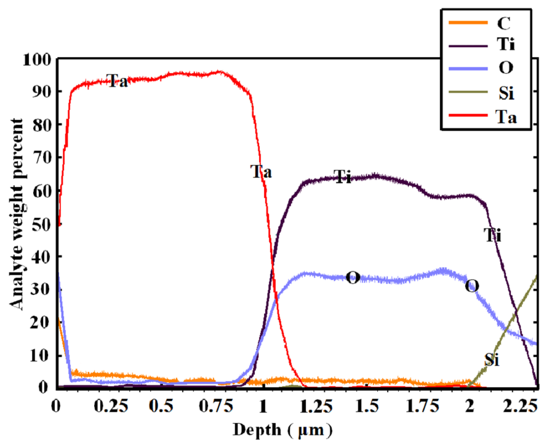
Figure 1. Surface layered chemical composition of the composite material with tantalum and titanium surface layers created for 30 min at 865 mA and 400 V with a distance of 150 mm, on a glass substrate.
Coatings 13 00114 g001
Figure 2. Results of energy-dispersive analysis of a multilayer composite material with tantalum and titanium surface layers created in 30 min at 400 V and 865 mA with a distance of 150 mm, on a TiNbMo base.
Coatings 13 00114 g002
Figure 3. Morphology of a composite material surface with (a) a titanium surface layer created in 30 min at 400 V and865 mA, with a distance of 250 mm, on a glass substrate and (b) a tantalum surface layer sputtered on the surface A at the same conditions.
Coatings 13 00114 g003
Figure 4. Morphology of the Ta-TiNbZr composite material created in 20 min at a distance of 40 mm.
Coatings 13 00114 g004
Figure 5. Dependence of the formed layers thickness on distance during magnetron sputtering of tantalum for 30 min at 400 V and 865 mA.
Coatings 13 00114 g005
Figure 6. Dependence of layer thickness on time for a composite obtained at 400 V, 865 mA at a distance of 200 mm.
Coatings 13 00114 g006
Figure 7. Dependence of layer thickness on power for a composite obtained for 30 min of tantalum sputtering at a distance of 150 mm.
Coatings 13 00114 g007
Figure 8. Layered composition of the surface of a composite material with a tantalum–titanium surface layer created in 30 min at 400 V and 865 mA with a distance of 250 mm, on a TiNbMo substrate.
Coatings 13 00114 g008
Figure 9. Layered composition of the surface of a composite material with a tantalum–titanium surface layer created in 30 min at 400 V and 865 mA with a distance of 150 mm, on a TiNbMo substrate.
Coatings 13 00114 g009
Figure 10. Layered composition of the surface of a composite material with a tantalum–titanium surface layer, created in 30 min at 400 V and 865 mA with a distance of 150 mm, on an aluminum substrate.
Coatings 13 00114 g010
Figure 11. Distribution of elements in a cross section of a composite material with a tantalum–titanium surface layer, created in 30 min at 400 V and 865 mA with a distance of 250 mm (the thickness is 0.4 µm), on an aluminum substrate.
Coatings 13 00114 g011
Figure 12. Distribution of elements in a cross section of a composite material with a tantalum–titanium surface layer, created in 30 min at 400 V and 865 mA with a distance of 150 mm (the thickness is 0.9 µm), on an aluminum substrate.
Coatings 13 00114 g012
Figure 13. Distribution of elements in a cross section of a composite material with a tantalum–titanium surface layer created in 30 min at 400 V and 865 mA with a distance of 150 mm (the thickness is 0.9 µm), on a TiNbMo substrate.
Coatings 13 00114 g013
Figure 14. Distribution of elements in the surface of a composite material with a tantalum–titanium surface layer, created in 30 min at 400 V and 865 mA with a distance of 250 mm (the thickness is 0.4 µm), on an aluminum substrate.
Coatings 13 00114 g014
Figure 15. Distribution of elements in the surface of a composite material with a tantalum–titanium surface layer, created in 30 min at 400 V and 865 mA with a distance of 150 mm (the thickness is 0.9 µm), on an aluminum substrate.
Coatings 13 00114 g015
Figure 16. Distribution of elements in the surface of a composite material with a tantalum–titanium surface layer, created in 30 min at 400 V and 865 mA with a distance of 150 mm (the thickness is 0.9 µm), on a TiNbMo substrate.
Coatings 13 00114 g016
Figure 17. Sample with TiNi base and Ti surface layer created in 30 min, at 400 V and 865 mA with a distance of 150 mm.
Coatings 13 00114 g017
Figure 18. X-ray patterns of samples of a multilayer composite material with tantalum on titanium surface layers created in 30 min, at 400 V and 865 mA with a distance of 250 mm, on a glass substrate.
Coatings 13 00114 g018
Figure 19. TiNbZr sample after magnetron sputtering of a Ta–Ti target created in 30 min, at 400 V and 865 mA with a distance of 250 mm.
Coatings 13 00114 g019
Figure 20. Al sample after magnetron sputtering of a Ta–Ti target created in 30 min, at 400 V and 865 mA with a distance of 250 mm.
Coatings 13 00114 g020
Table 1. Mechanical properties of Ti-Nb-Zr wire after surface treatment and composite material based on it.
No.SampleRel. ext.Yield Strength (MPa)Tensile Strength (MPa)Load (kgf)Young’s Modulus (GPa)
1Ti-Nb-Zr3.05583.68671.5844.5827.571
2Ti-Nb-Zr–Ti, 30 min3.21419.79579.4347.1925.675
3Ti-Nb-Zr–Ti–Ta, 30 min3.65448.75619.6745.4223.278
4Ti-Nb-Zr–Ta/Ti, 30 min3.67451.24618.7247.1222.589
Disclaimer/Publisher’s Note: The statements, opinions and data contained in all publications are solely those of the individual author(s) and contributor(s) and not of MDPI and/or the editor(s). MDPI and/or the editor(s) disclaim responsibility for any injury to people or property resulting from any ideas, methods, instructions or products referred to in the content.