Article

A Comparative Study of Organic Dye-Sensitized Solar Cells Based on Anatase TiO2 and Amorphous Free Mixed Phase’s Anatase/Rutile P25 TiO2 Photoanodes

1
Department of Physics, College of Science, University of Kerbala, Karbala 56001, Iraq
2
Institute for Superconducting and Electronic Materials (ISEM), Australian Institute for Innovative Materials (AIIM), University of Wollongong, North Wollongong, NSW 2500, Australia
3
Intelligent Polymer Research Institute (IPRI), Australian Institute for Innovative Materials (AIIM), University of Wollongong, North Wollongong, NSW 2500, Australia
4
School of Chemistry, Monash University, VIC 3800, Australia
*
Author to whom correspondence should be addressed.
Coatings 2023, 13(1), 121; https://doi.org/10.3390/coatings13010121
Submission received: 2 December 2022 / Revised: 30 December 2022 / Accepted: 4 January 2023 / Published: 9 January 2023

Abstract

:
Dye-sensitized solar cells (DSCs) remain an interesting photovoltaic concept, although recent times have seen their envisioned broad-scale applications being replaced with more niche ones. Nevertheless, as a key component of DSCs, titanium(IV) oxide (TiO2) must be produced in a large volume, low cost, and highly reproducible manner. Degussa P25 remains a benchmark TiO2 product, addressing the first two of the above points very well. Post-treatment processes that may also be carried out on a large scale give some hope to addressing the reproducibility issue. This paper builds on our previous works wherein mixed-phase P25 (anatase + rutile + amorphous TiO2) was converted into an amorphous free form by selectively dissolving and recrystallizing the amorphous component. Here we investigated the performance of metal-free organic dye (D149)-based DSCs with three different TiO2 films: (1) as-received P25 (TiO2-P25), (2) amorphous-free P25 (TiO2-HP25), and (3) anatase nanoparticles obtained from Dyesol (TiO2-DSL). DSCs based on TiO2-HP25 showed comparable performance (5.8 ± 0.2% PCE) to DSCs based on the TiO2-DSL (5.8 ± 0.4% PCE) and substantially higher than for devices based on the as-obtained P25 nanoparticles (3.9 ± 0.4% PCE). The enhancement resulting from the post-processing of P25 derives from simultaneous increases in photo-current density (Jsc), open-circuit voltage (VOC), and the fill factor (FF), due to enhancing the dye-loading capability and the charge-transport efficiency (suppressing the electron recombination) as a result of the removal of amorphous barriers and associated defect states. This is in line with enhancing DSC performance based on the organometallic N719 dye we reported previously. However, the photoanode material based on abundant P25 TiO2 sensitized with high-extinction-coefficient organic D149 dye can be adopted as a cost-effective DSC as an alternative to relatively high-cost DSCs based on the commercial anatase TiO2 sensitized with organometallic N719 dye.

1. Introduction

Dye-sensitized solar cells (DSCs) are a second-generation photovoltaic technology first reported and developed by O’Regan and Gratzel in 1991 [1,2]. DSCs offer the prospect of high-volume production, as their manufacture is amenable to roll-to-roll coating processes [3]. In recent years the cost of silicon-based photovoltaic (PV) panels has dropped substantially, limiting interest in further development of DSCs for applications such as utility-scale PV. On the other hand, DSCs are well suited to domestic and indoor applications due to their colourful designs, semitransparency, and ability to retain operating efficiencies even in lowdiffuse-light conditions as well as under partial shading [4,5,6,7]. Furthermore, the judicious selection of organic components allows for spectral matching, as is desired with artificial light sources.
A typical DSC consists of a porous-oxide semiconductor photoanode, an organic/organometallic sensitizer, a redox-active electrolyte, and a non-photoactive cathode [1,2]. The photoanode is typically made with 2–20 micrometer-thick film semiconductor nanoparticles (such as titanium dioxide (TiO2)) deposited on a transparent conducting oxide-coated glass (TCO). The loading and absorption coefficient of the sensitizer largely dictates the thickness of TiO2 film required to attain high light-harvesting efficiency. One other significant factor here is the prevention of charge recombination, which scales with the interfacial area between the semiconductor and the electrolyte (typically either iodide-triiodide or cobalt(II/III) based electrolyte) and hence becomes a more substantial problem as film thickness increases. The aforementioned mediator is regenerated at a catalytic surface such as platinum [1,2].
Around 40% of scientific publications on DSCs have focused on optimizing photoanode materials [1,2], with the highest efficiencies reported for devices using pure-anatase TiO2. We previously synthesized high-surface-area anatase TiO2 nanoparticles with a higher isoelectric point (IEP) compared to the commercial anatase TiO2 (Dyesol). These synthesized anatase nanoparticles showed higher photovoltaic conversion efficienct when applied as a photoanode compared to commercial Dyesol anatase nanoparticles when using the organic dye D149. The enhancement was attributed to the higher dye loading due to the higher IEP of the synthesized anatase TiO2 nanoparticles. [8]. On the other hand, the commercially available product P25 from Degussa, a mixture of the anatase and rutile phases of TiO2, along with some amorphous content, is an attractive alternative due to the simplicity and scale of its synthesis.
DSC performances using P25 are usually quite poor in comparison with the aforementioned pure anatase materials [9], and it has routinely been argued that low surface area and the more positive conduction-band edge of rutile are responsible for the lower photocurrent and voltage, respectively. On the other hand, studies by both Park and Lin showed that rutile TiO2, with a comparable surface area to anatase TiO2, achieved a similar performance and as such the rutile component is not itself the reason for the low efficiencies seen for P25-based DSCs [10,11]. Dye loading/binding on TiO2 nanoparticles is known to differ according to the exposed facet [12]. Amorphous TiO2 has a flat surface without distinct facets [13]. This morphology leads to poor dye packing, which both decreases the total light harvesting and provides opportunities for charge recombination between the mediator and TiO2 [14,15,16].
Recognizing this issue, P25 has been modified using a hydrothermal process to selectively convert the amorphous TiO2 to a crystalline form. This amorphous-free P25 (H-P25) was first applied as a photocatalyst and showed a significant enhancement in activity compared to untreated P25 [17]. More recently we applied this material as a photoanode sensitized with commonly used organometallic N719 dye, seeing a ~65% enhancement in photovoltaic efficiency compared to devices based on untreated P25 [18]. Other authors have reported alternate approaches to the removal of amorphous TiO2, such as Kurian et al., who used a water-treatment approach, which also led to enhanced DSC efficiencies [19]. Mohammadi et al. compared DSC performance based on either anatase TiO2 or rutile TiO2 or composite anatase/rutile nanoparticles as photoanode materials [20]. Anatase TiO2-based photoanode sensitized with N719 dye showed higher performance than rutile TiO2, whereas the composite anatase/rutile photoanode showed the highest performance. It can be concluded that the commercially available mixed anatase/rutile TiO2 (P25) can be adopted as a cost-effective photoanode material based on organic DSCs.
It is noted that for the two studies mentioned above (ours and Kurian et al.’s) ruthenium-based sensitizers were used. These have low extinction coefficients (<2 × 10⁴ M−1 cm−1), which, when combined with the lower surface area of TiO2-P25, limit the light harvesting and hence the photocurrent. On the other hand, organic dyes typically offer high extinction coefficients (up to 2 × 10⁵ M−1 cm−1). Here we see that using such dyes helps to alleviate this issue. Meanwhile, organic dyes also have other attractive attributes, such as being comprised solely of earth-abundant elements, thus minimizing uncertainties around the future supply of precursors for their synthesis and having more readily tuneable colours to match light sources/aesthetic considerations [21,22,23]. In this work we compare DSC performance based on three photoanode materials: as-received P25 nanoparticles (TiO2-P25), amorphous-free TiO2 P25 (TiO2-HP25), and as-received Dyesol NR18-T TiO2 nanoparticles (TiO2-DSL), all sensitized with D149, a model high extinction coefficient-metal free organic dye.

2. Experiment

2.1. Materials Synthesis

Commercially sourced P25 was hydrothermally treated by our group as previously reported [17,18]. In brief, tetrapropylammonium hydroxide (TPA, 40% in water) (Tokyo Chemical Industry Co., Ltd., Tokyo, Japan), distilled water, ammonium fluoride (NH4F) (Kanto Chemical Co., Inc., Tokyo, Japan), and P25 (Nippon Aerosil, Tokyo, Japan) were mixed at a molar ratio of 5:4:25:1 (P25:TPA:H2O:NH4F). This was then hydrothermally treated for 7 days at 170 °C using an autoclave. TiO2-HP25 was obtained after washing three times with distilled water and ethanol using a centrifuge before being dried at 90 °C for three hours. TiO2-DSL was supplied as prepared from Dyesol, Queanbeyan, NSW, Australia, as a paste product (NR18-T). TiO2-HP25 and TiO2-P25 photoanodes were deposited as follows: TiO2-HP25 or TiO2-P25 powder (1.0 g) was ground in Milli-Q water(1.0 mL, Sartorius Stedim Biotech, Victoria, Australia), absolute ethanol (25 mL, Sigma, Castle Hill, NSW, Australia), and acetic acid (0.2 mL, Sigma, Castle Hill, NSW, Australia). An ethyl cellulose (Sigma, Castle Hill, NSW, Australia) solution was prepared in ethanol (10% w/w) and was added to the nanoparticle suspension, along with terpineol (5.0 g, Sigma, Castle Hill, NSW, Australia). This was then stirred and sonicated at 50 °C for 1.0 h. Following this, a rotary evaporator was employed (50 °C for 2 h) to evaporate water and ethanol from the pastes [24].

2.2. DSC Devices Assembly

Fluorine-doped tin-oxide (FTO) glass substrate was cleaned thoroughly using soapy water, acetone, and ethanol subsequently. A blocking layer of TiO2 was sprayed on the FTO substrate using a (1:9 v/v) solution of diluted titanium diisopropoxide bis (acetylacetonate) (75% in isopropanol, Sigma, Castle Hill, NSW, Australia) in absolute ethanol. TiO2-HP25, TiO2-P25, and TiO2-DSL films were screen printed (Keywell semi-automatic screen printer, Kang Yuan Industrial Co. Wufeng Shiang, Taiwan ) onto the FTO substrate to obtain film thicknesses of 11.5 ± 0.3 µm and areas of 0.16 cm2 (4mm × 4mm). The films were annealed for 3 h at 450 °C to remove the organic binders [24]. A post-treatment step of titanium chloride (TiCl4) was applied to the sintered films by immersing them in an aqueous solution of TiCl4 (20 mM, Sigma, Castle Hill, NSW, Australia ) for half an hour at 70 °C before rinsing with ethanol and then again with water before re-sintering for one hour at 500 °C. After being cooled down to 110 °C, the films were soaked overnight in a D149 (1-material, Dorval, Quebec, Canada) dye bath at a concentration of 0.5 mM in a 1:1 v/v mixture of acetonitrile and tert-butanol. After the photoanodes were taken from the dye solution, they were washed with acetonitrile and dried at 110 °C. The counter electrode (cathode) was produced by casting ~10 µL (H2PtCl6) (0.01 M, Sigma, Castle Hill, NSW, Australia ), then treating it at 450 °C for 30 min to reduce the platinum to Pt0. Working electrodes (photoanodes) were affixed to counter electrodes using a 25 μm Surlyn spacer (Solaronix, Aubonne, Switzerland). The electrolyte consisted of iodine (50 mM, Sigma, Castle Hill, NSW, Australia), 1,2-dimethyl-3-propylimidazelium iodide (0.6 M, Solaronix, Aubonne, Switzerland), and lithium iodide (0.1 M, 99% Acros Organics, ThermoFisher, who are based in Scoresby, Vic, Australia ) in 3-methoxypropionitrile (≥ 98% Sigma, Castle Hill, NSW, Australia) and was injected between the two assembled electrodes using a vacuum back-filling approach. Finally, Surlyn-laminated aluminium foil was used to seal the filling port.

2.3. Material and Device Characterizations

The X-ray diffractometer (GBC Scientific Equipment LLC, Hampshire, Illinois, USA) was used to examine the crystalline structure of materials (Scan range = 20°–80°, Voltage = 40 kV, Current = 30 mA, Target = Cu Kα radiation, Wavelength = 1.54 Å). Transmission electron microscopy (TEM) (JEOL JEM-6500F, Tokyo, Japan) was used to examine the nanostructure of the materials. Brunauner–Emmet–Teller (BET) analysis was conducted on N2 adsorption–desorption data, obtained using a MicrotracBel Belsorp-mini,Osaka, Japan) to quantify the specific surface area. D149 dye was desorbed from material films after being immersed in NaOH (0.4 M) in methanol for 5 min. Absorption spectroscopy (UV-Vis, Shimadzu UV-1800, Rydalmere, NSW, Australia) was used to calculate the dye loading on the photoanodes by measuring the absorption spectra of the aforementioned solutions. Film thicknesses were measured by Surface Profiler-Veeco Dektak 150 (NewSpec, Myrtle Bank, SA, Australia). The photocurrent density–voltage (J-V) measurements under 1 sun condition (100 mW/cm2) with an AM1.5 filter were conducted with a solar simulator (PV Measurements, Boulder, Colorado, USA). A QEX10 system from (PV Measurements, Boulder, Colorado, USA) was used to measure incident photon to current conversion efficiencies (IPCEs). Electrochemical impedance spectroscopy measurements for three devices were measured with a Gamry Reference 600 workstation (Gamry Instrument,Warminster, USA)) under illumination at Voc in the frequency range of 0.1–106 Hz and using an AC voltage of 10 mV.

3. Results and Discussions

3.1. Material Structure Analysis

X-ray diffraction (XRD) traces, shown in Figure 1d, indicate that, as expected, TiO2-P25 and TiO2-HP25 contained a mixture of anatase and rutile, whereas TiO2-DSL only showed anatase. This is in line with what we reported in our previous work [18]. We also note that the amorphous TiO2 could not be directly observed by XRD. The amount of amorphous TiO2 in TiO2-P25 and TiO2-HP25 before and after the hydrothermal treatment was investigated and quantified in our previous report as 76:13:11 anatase: rutile: amorphous wt.% and 81:19:0 anatase: rutile: amorphous wt.% [17,18]. Average grain sizes were obtained using the Scherrer formula (D = 0.89λ/β cosθ, where D is the grain size, λ the wavelength of the X-ray, β the full-width half-maximum in radians, and θ the diffraction angle). From this, the crystal size was estimated to be 20 nm in TiO2-DSL, whereas both TiO2-HP25 and TiO2-P25 revealed values of around 30 nm and 34 nm for the anatase and rutile phases, respectively.
As can be seen in the TEM in Figure 1a–c, TiO2-HP25 was more aggregated compared to TiO2-P25. This was presumably a result of the hydrothermal treatment resulting in crystal growth focused at the junction of particles, in a similar manner to necking occurring during the sintering process. These images show that TiO2-DSL had particle size of 15 ± 7 nm, whereas TiO2-HP25 and TiO2-P25 had a similar particle size of 28 ± 8 nm (see insets in Figure 1a–c, along with Figures S1 and S2), which were within the range of the above values, calculated from the XRD data. The average particle size of the materials was quantified by a Digital Gatan Micrograph and Image J software based on measuring the aspect ratio of the width to the height of the particle image, as shown in Figures S1 and S2.
The surface area and pore-size distribution of three types of nanoparticles were investigated by Brunauer–Emmett–Teller (BET) measurements. As shown in Figure 1e and its inset, TiO2-DSL nanoparticles had the highest surface area of the three materials investigated here, resulting from their smaller particle size and good dispersion. TiO2-HP25 nanoparticles had a slightly smaller surface area than TiO2-P25 nanoparticles, which was primarily ascribed to the aggregation, as discussed above. The type IV isotherm indicated pore diameters of 2–50 nm, which represents a mesoporous structure of all the materials [25]. The inset in Figure 1e shows the pore-size distribution range of the materials and their average pore diameters obtained from the Barrett–Joyner–Halenda (BJH) analysis. In general, when the particle size increased, the surface area increased and the average pore size decreased. From the BET-based nitrogen isotherm adsorption, the more nitrogen adsorption on nanoparticles means a higher surface area, resulting in a smaller average pore size, depending on the voids or pores among the nanoparticles. The different pore-size distributions of the three materials indicate the different surface areas and determine the capability of dye loading on the materials.
The amount of D149 adsorbed on the photoanode films was quantified by a dye-desorption method [26]. As shown in Figure 1f, TiO2-DSL possessed the highest loading, as was to be expected, given that it also possessed the highest specific surface area. Meanwhile, TiO2-HP25 showed greater dye adsorption than TiO2-P25, despite having a lower surface area.
The dye loading can be normalized against the specific surface area to give a better understanding of the way dyes pack onto the surface. From this, it can be seen that the dye packing on TiO2-HP25 was closer to that of TiO2-DSL than that of TiO2-P25, indicating the degree to which the amorphous content disproportionately impacts surface chemistry, despite only representing around 11 wt% of P25. The obtained BET data, the specific surface area (SA), the average pore diameter, and the amount of desorbed dye of TiO2-DSL, TiO2-P25, and TiO2-P25 are listed in Table 1.

3.2. Photovoltaic Performance of DSCs

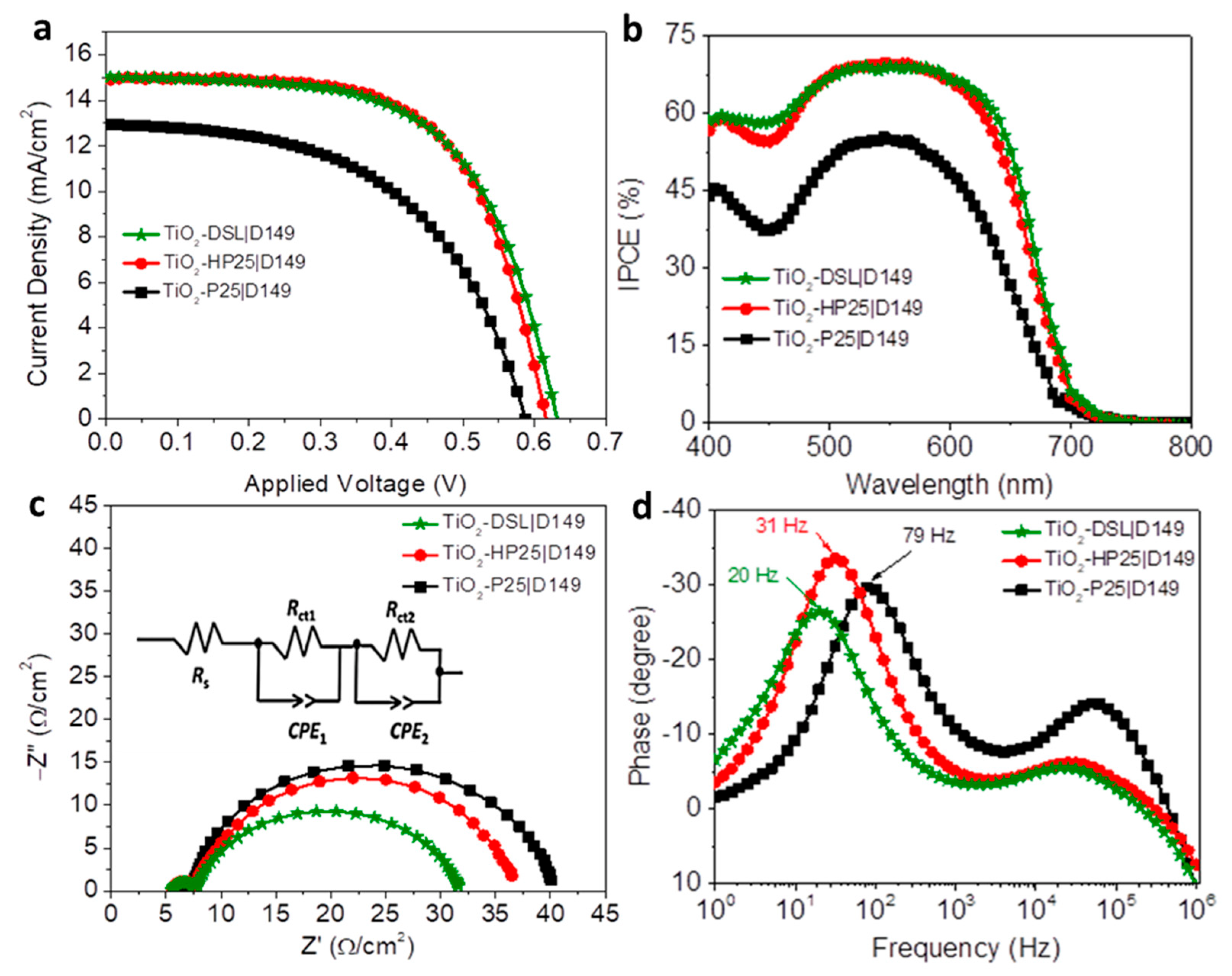
Photocurrent-voltage measurements performed under 1 sun illumination showed very similar performances between TiO2-DSL|D149 and TiO2-HP25|D149, with both showing around 45% higher overall photovoltaic conversion efficiency (PCE) than for TiO2-P25|D149 devices. As shown in Table 2 as well as in Figure 2a, there was a simultaneous improvement in photocurrent density (Jsc), open-circuit voltage (Voc), and fill factor (FF) for TiO2-HP25|D149 compared to the untreated P25. Figure 2b shows the IPCE measurements, which agreed with the trend in Jsc values, with very similar responses for TiO2-DSL|D149 and TiO2-HP25|D149. Two regions (430–460 nm and >650 nm) were noted to show a slight difference in favour of the TiO2-DSL devices, which may be explained by the higher overall dye loading; however, it was not enough to lead to a difference in JSC above the experimental variability (one standard deviation, based on multiple devices). The absorbance spectra of D149 dye adsorbed on TiO2-DSL, TiO2-P25, and TiO2-HP25 photoanodes and IPCEs values of their corresponding devices to estimate the absorbed photon to charge carrier efficiencies (APCE). The APCE values had a similar trend to the IPCE values, which explains the difference in device performance. (see Figure S3a,b).
To further investigate the charge transport in these devices, electrochemical impedance spectroscopy (EIS) measurements were conducted and are represented by Nyquist and Bode plots in Figure 2c,d. These were collected at VOC under 1 sun illumination with a perturbation voltage of 10 mV. Key parameters taken from these are shown in Table 3. The Nyquist plots (Figure 2c) all showed two depressed semicircles, with the inset showing the equivalent circuit model used to interpret these data. In this, Rct1 and Rct2 are the electrochemical impedances, which refers to the charge-transfer resistances at high and mid-range frequencies fitted by the first and second semicircles, respectively. CPE1 and CPE2 refer to the constant-phase elements (considered a double-layer capacitor at a solid–liquid interface with non-ideal or “leaky” capacitance), with Rct1 and Rct2 at cathode–electrolyte and photoanode–electrolyte interfaces, respectively [25]. Rs is the overall series resistance of the device.
As Rct1 refers to the charge transfer at the cathode–electrolyte interface and Rs is the series contact resistance, their values were expected to be similar for all three systems, as shown in Table 3. TiO2-DSL|D149 showed the lowest Rct2, whereas, TiO2-P25|D149 showed the highest Rct2, indicating the lowest and highest charge recombination at the photoanode–electrolyte interface, respectively. Rct2 was decreased slightly in TiO2-HP25|D149 devices compared to TiO2-P25|D149 due to the absence of amorphous TiO2. Amorphous content was expected to lead to recombination due to (1) defect sites and (2) lower dye-packing density, directly exposing more of the semiconductor to the electrolyte. The chemical capacitance (Cµ) of the devices showed an opposite trend to Rct2, but to a much greater degree. The higher values of Cµ indicates that there was a higher density of shallow traps in the TiO2-DSL and TiO2-HP25 nanoparticle surface, resulting in a greater capability to receive electrons compared to TiO2-P25. The Bode plots in Figure 2d provide us with important frequency-based information. The low-range maxima show the values of electron lifetimes obtained from (τn = 1/2 π f max) [26], with similar values for TiO2-DSL|D149 and TiO2-HP25|D149 devices, indicating longer electron lifetimes (lower electron recombination rate) compared to TiO2-P25|D149 devices, and consistent with the difference shown in FF values in photovoltaic measurements.

4. Conclusions

Dye-sensitized solar cells based on an organic dye and a modified form of one of the cheapest sources of TiO2 (P25) were produced and compared against both untreated P25 and a benchmark commercially available product specifically designed for this application, NR18-T (Dyesol). The amorphous content-free P25 (TiO2-HP25|D149) devices showed higher solar performance than untreated P25 (TiO2-P25|D149), which was very similar to those using the Dyesol product (TiO2-DSL|D149). The enhanced performance resulting from the treatment of P25 is explained by higher dye-loading and packing densities, as well as a decrease in recombination sites. The process used to treat TiO2-P25 is time-consuming; however, it does suggest that with further optimization this may be a viable pathway to making photoanodes. This amorphous content-free P25 can be considered as a cost-effective photoanode material for organic dye-sensitized or perovskite solar cells.

Supplementary Materials

The following supporting information can be downloaded at: https://www.mdpi.com/article/10.3390/coatings13010121/s1, Figure S1: Average particle size of TiO2-DSL, TiO2-P25, and TiO2-HP25 nanoparticles obtained by Gatan Digital Micrograph Spectroscopy (GMS). The average particle size of materials is quantified based on measuring the aspect ratio of the width to the height of the particle image. Figure S2: Particle size distribution of TiO2-DSL, TiO2-P25, and TiO2-HP25 nanoparticles obtained by Image J. The average particle size of materials is quantified based on measuring the aspect ratio of the width to the height of the particle image. Figure S3: (a) Absorbance spectra of D149 dye adsorbed on TiO2-DSL, TiO2-P25, and TiO2-HP25 photoanodes and, (b) The Absorbed Photon to Charge carrier Efficiencies (APCE) of their corresponding devices.

Author Contributions

Conceptualization, K.A.-A., A.N. and J.H.K.; methodology, K.A.-A., M.H.D., H.A.M. and A.N.; software, K.A.-A., M.H.D. and H.A.M.; validation, K.A.-A., M.H.D., H.A.M. and A.N.; formal analysis, K.A.-A. and A.N.; investigation, K.A.-A., M.H.D., A.N. and J.H.K.; resources, H.A.M.; data curation, K.A.-A.; writing—original draft, K.A.-A.; writing—review and editing, K.A.-A., H.A.M. and A.N.; visualization, K.A.-A., M.H.D., A.N. and J.H.K.; supervision, A.N. and J.H.K.; project administration, J.H.K.; funding acquisition, J.H.K. All authors have read and agreed to the published version of the manuscript.

Funding

This research was conducted with funds from the Australian Research Council (DE160100504), National Research Foundation of Korea (NRF) [NRF-2018R1A5A1025594] as well as the Higher Committee for Education Development in Iraq (HCED) and Ministry of Higher Education and Scientific Research, University of Kerbala, Iraq.

Institutional Review Board Statement

Not applicable.

Informed Consent Statement

Not applicable.

Data Availability Statement

Not applicable.

Acknowledgments

The authors would like to acknowledge the Australian Institute for Innovative Materials (AIIM), University of Wollongong, Australia, for access to equipment; the Higher Committee for Education Development (HCED); and the Ministry of Higher Education & Scientific Research, University of Kerbala, Iraq, for the financial support.

Conflicts of Interest

The authors declare no conflict of interest.

References

  1. O’Regan, B.; Grätzel, M. A low-cost, high-efficiency solar cell based on dye-sensitized colloidal TiO2 films. Nature 1991, 353, 737–740. [Google Scholar] [CrossRef]
  2. Ye, M.; Wen, X.; Wang, M.; Iocozzia, J.; Zhang, N.; Lin, C.; Lin, Z. Recent advances in dye-sensitized solar cells: From photoanodes, sensitizers and electrolytes to counter electrodes. Mater. Today 2015, 18, 155–162. [Google Scholar] [CrossRef]
  3. Krebs, F.C.; Tromholt, T.; Jørgensen, M. Upscaling of polymer solar cell fabrication using full roll-to-roll processing. Nanoscale 2010, 2, 873–886. [Google Scholar] [CrossRef] [PubMed]
  4. Rasheduzzaman, M.; Pillai, P.B.; Mendoza, A.N.C.; De Souza, M.M. A study of the performance of solar cells for indoor autonomous wireless sensors. In Proceedings of the 2016 10th International Symposium on Communication Systems, Networks and Digital Signal Processing (CSNDSP), Prague, Czech Republic, 20–22 July 2016; pp. 1–6. [Google Scholar]
  5. Yoon, S.; Tak, S.; Kim, J.; Jun, Y.; Kang, K.; Park, J. Application of transparent dye-sensitized solar cells to building integrated photovoltaic systems. Build. Environ. 2011, 46, 1899–1904. [Google Scholar] [CrossRef]
  6. Freitag, M.; Teuscher, J.; Saygili, Y.; Zhang, X.; Giordano, F.; Liska, P.; Hua, J.; Zakeeruddin, S.M.; Moser, J.-E.; Grätzel, M.; et al. Dye-sensitized solar cells for efficient power generation under ambient lighting. Nat. Photon. 2017, 11, 372–378. [Google Scholar] [CrossRef] [Green Version]
  7. Al-Attafi, K.; Nattestad, A.; Qutaish, H.; Park, M.S.; Shrestha, L.K.; Ariga, K.; Dou, S.X.; Kim, J.H. Solvothermally synthesized anatase TiO2 nanoparticles for photoanodes in dye-sensitized solar cells. Sci. Technol. Adv. Mater. 2021, 22, 100–112. [Google Scholar] [CrossRef]
  8. Fan, K.; Yu, J.; Ho, W. Improving photoanodes to obtain highly efficient dye-sensitized solar cells: A brief review. Mater. Horiz. 2017, 4, 319–344. [Google Scholar] [CrossRef]
  9. Park, N.-G.; van de Lagemaat, J.; Frank, A.J. Comparison of Dye-Sensitized Rutile- and Anatase-Based TiO2 Solar Cells. J. Phys. Chem. B 2000, 104, 8989–8994. [Google Scholar] [CrossRef] [Green Version]
  10. Lin, J.; Heo, Y.-U.; Nattestad, A.; Sun, Z.; Wang, L.; Kim, J.H.; Dou, S.X. 3D Hierarchical Rutile TiO2 and Metal-free Organic Sensitizer Producing Dye-sensitized Solar Cells 8.6% Conversion Efficiency. Sci. Rep. 2014, 4, 5769. [Google Scholar] [CrossRef] [Green Version]
  11. Chen, C.; Ikeuchi, Y.; Xu, L.; Sewvandi, G.A.; Kusunose, T.; Tanaka, Y.; Nakanishi, S.; Wen, P.; Feng, Q. Synthesis of [111]- and {010}-faceted anatase TiO2 nanocrystals from tri-titanate nanosheets and their photocatalytic and DSSC performances. Nanoscale 2015, 7, 7980–7991. [Google Scholar] [CrossRef]
  12. Li, C.; Koenigsmann, C.; Ding, W.; Rudshteyn, B.; Yang, K.R.; Regan, K.P.; Konezny, S.J.; Batista, V.S.; Brudvig, G.W.; Schmuttenmaer, C.A.; et al. Facet-Dependent Photoelectrochemical Performance of TiO2 Nanostructures: An Experimental and Computational Study. J. Am. Chem. Soc. 2015, 137, 1520–1529. [Google Scholar] [CrossRef]
  13. Fang, W.Q.; Yang, X.H.; Zhu, H.; Li, Z.; Zhao, H.; Yao, X.; Yang, H.G. Yolk@ shell anatase TiO2 hierarchical microspheres with exposed {001} facets for high-performance dye sensitized solar cells. J. Mater. Chem. 2012, 22, 22082–22089. [Google Scholar] [CrossRef] [Green Version]
  14. Chen, C.; Sewvandi, G.A.; Kusunose, T.; Tanaka, Y.; Nakanishi, S.; Feng, Q. Synthesis of {010}-faceted anatase TiO2 nanoparticles from layered titanate for dye-sensitized solar cells. CrystEngComm 2014, 16, 8885–8895. [Google Scholar] [CrossRef]
  15. Ide, Y.; Inami, N.; Hattori, H.; Saito, K.; Sohmiya, M.; Tsunoji, N.; Komaguchi, K.; Sano, T.; Bando, Y.; Golberg, D.; et al. Remarkable Charge Separation and Photocatalytic Efficiency Enhancement through Interconnection of TiO2 Nanoparticles by Hydrothermal Treatment. Angew. Chem. Int. Ed. 2016, 55, 3600–3605. [Google Scholar] [CrossRef]
  16. Al-Attafi, K.; Nattestad, A.; Wu, Q.; Ide, Y.; Yamauchi, Y.; Dou, S.X.; Kim, J.H. The effect of amorphous TiO2 in P25 on dye-sensitized solar cell performance. Chem. Commun. 2018, 54, 381–384. [Google Scholar] [CrossRef]
  17. Kurian, S.; Sudhagar, P.; Lee, J.; Song, D.; Cho, W.; Lee, S.; Kang, Y.S.; Jeon, H. Formation of a crystalline nanotube–nanoparticle hybrid by post water-treatment of a thin amorphous TiO2 layer on a TiO2 nanotube array as an efficient photoanode in dye-sensitized solar cells. J. Mater. Chem. A 2013, 1, 4370–4375. [Google Scholar] [CrossRef]
  18. Mohammadi, M.; Louca, R.; Fray, D.; Welland, M. Dye-sensitized solar cells based on a single layer deposition of TiO2 from a new formulation paste and their photovoltaic performance. Sol. Energy 2012, 86, 2654–2664. [Google Scholar] [CrossRef]
  19. Ito, S.; Murakami, T.N.; Comte, P.; Liska, P.; Grätzel, C.; Nazeeruddin, M.K.; Grätzel, M. Fabrication of thin film dye sensitized solar cells with solar to electric power conversion efficiency over 10%. Thin Solid Film. 2008, 516, 4613–4619. [Google Scholar] [CrossRef]
  20. Ito, S.; Zakeeruddin, S.M.; Humphry-Baker, R.; Liska, P.; Charvet, R.; Comte, P.; Nazeeruddin, M.K.; Péchy, P.; Takata, M.; Miura, H.; et al. High-Efficiency Organic-Dye- Sensitized Solar Cells Controlled by Nanocrystalline-TiO2 Electrode Thickness. Adv. Mater. 2006, 18, 1202–1205. [Google Scholar] [CrossRef]
  21. Lee, C.-P.; Lin, R.Y.-Y.; Lin, L.-Y.; Li, C.-T.; Chu, T.-C.; Sun, S.-S.; Lin, J.T.; Ho, K.-C. Recent progress in organic sensitizers for dye-sensitized solar cells. RSC Adv. 2015, 5, 23810–23825. [Google Scholar] [CrossRef]
  22. Lin, J.; Nattestad, A.; Yu, H.; Bai, Y.; Wang, L.; Dou, S.X.; Kim, J.H. Highly connected hierarchical textured TiO2 spheres as photoanodes for dye-sensitized solar cells. J. Mater. Chem. A 2014, 2, 8902–8909. [Google Scholar] [CrossRef]
  23. Anovitz, L.M.; Cole, D.R. Characterization and Analysis of Porosity and Pore Structures. Rev. Miner. Geochem. 2015, 80, 61–164. [Google Scholar] [CrossRef] [Green Version]
  24. Wayment-Steele, H.K.; Johnson, L.E.; Tian, F.; Dixon, M.C.; Benz, L.; Johal, M.S. Monitoring N3 Dye Adsorption and Desorption on TiO2 Surfaces: A Combined QCM-D and XPS Study. ACS Appl. Mater. Interfaces 2014, 6, 9093–9099. [Google Scholar] [CrossRef] [PubMed]
  25. Bisquert, J. Theory of the impedance of charge transfer via surface states in dye-sensitized solar cells. J. Electroanal. Chem. 2010, 646, 43–51. [Google Scholar] [CrossRef]
  26. Kern, R.; Sastrawan, R.; Ferber, J.; Stangl, R.; Luther, J. Modeling and interpretation of electrical impedance spectra of dye solar cells operated under open-circuit conditions. Electrochim. Acta 2002, 47, 4213–4225. [Google Scholar] [CrossRef]
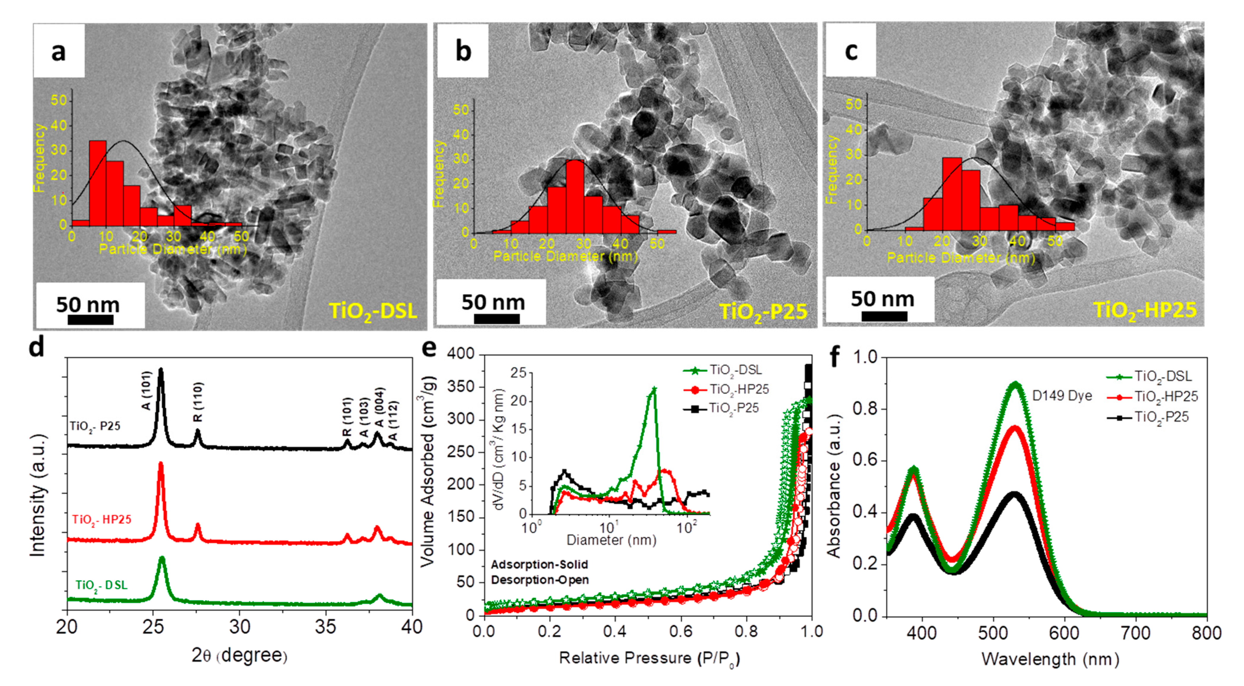
Figure 1. (ac) TEM images, (d) XRD diffraction patterns, and (e) BET and BJH isotherm plots of TiO2-DSL, TiO2-HP25, and TiO2-P25 nanoparticles. (f) Absorbance spectra of desorbed D149 dye from TiO2-DSL, TiO2-HP25, and TiO2-P25 thin films.
Coatings 13 00121 g001
Figure 2. (a) Photocurrent-voltage (J-V) characterizations, (b) IPCE measurements, (c,d) EIS measurements, and Nyquist and Bode plots of TiO2-DSL|D149, TiO2-HP25|D149, and TiO2-P25|D149 devices.
Coatings 13 00121 g002
Table 1. The specific surface area (SA), the average pore diameter (DP), and the amount of desorbed dye per unit area/volume of materials.
MaterialSA (m2·g−1)DP (nm)Dye Loading (µmol·cm−3)Dye Loading (nmol·cm−2)
TiO2-DSL792699 ± 164 ± 1
TiO2-HP25473742 ± 250 ± 1
TiO2-P25574127 ± 133 ± 1
Table 2. Photovoltaic measurements of TiO2-DSL|D149, TiO2-HP25|D149, and TiO2-P25|D149 devices.
DevicesJsc (mA·cm−2)VOC (V)FF (%)PCE (%)
TiO2-DSL|D14915.3 ± 0.90.608 ± 0.0162 ± 25.81 ± 0.4
TiO2-HP25|D14915.4 ± 0.40.620 ± 0.0260 ± 15.78 ± 0.2
TiO2-P25|D14913.3 ± 1.30.600 ± 0.0249 ± 43.89 ± 0.4
Table 3. EIS measurements of TiO2-DSL|D149, TiO2-HP25|D149, and TiO2-P25|D149 devices.
DevicesRS (Ω·cm−2)Rct1 (Ω·cm−2)Rct2 (Ω·cm−2)Cµ (µF·m−1)
TiO2-DSL|D1495.5 ± 0.12.2 ± 0.224.1 ± 0.31450 ± 100
TiO2-HP25|D1495.0 ± 0.12.5 ± 0.130.5 ± 0.3540 ± 40
TiO2-P25|D1495.2 ± 0.12.5 ± 0.133.5 ± 0.5210 ± 20
Disclaimer/Publisher’s Note: The statements, opinions and data contained in all publications are solely those of the individual author(s) and contributor(s) and not of MDPI and/or the editor(s). MDPI and/or the editor(s) disclaim responsibility for any injury to people or property resulting from any ideas, methods, instructions or products referred to in the content.