1. Introduction
The dictate of sustainability has placed much emphasis on weight reduction and the use of lightweight alloys [
1]. The impetus to increase fuel efficiency in automobiles and aviation is directed at reducing emissions [
2]. Using lightweight materials is one of the most significant options for enhancing fuel efficiency. Aluminium (Al), titanium (Ti), and magnesium (Mg) are among the primary metals that find application in the fabrication of automotive and aircraft parts [
3,
4,
5,
6]. Aluminium alloys with densities around 60% and 33% compared to stainless steel and titanium, respectively, find a place for such applications due to their weight and high specific strength.
Mg is 37% lighter than Al and has recently attracted much interest in weight reduction and lightweight applications. However, the continued pursuit of resources and waste reduction are the drivers for developing new materials. Metal foam is poised to bridge the gap. In addition to the weight reduction, metal foams offer shock absorption capacity during impacts and dampening in vibrating structures and acoustics [
7,
8,
9,
10]. The metal foam also provides good sound absorption capacity, thereby providing comfort [
11,
12,
13].
Apart from liquid, powder metallurgy is a popular route for producing Al-metal foams. The aluminium metal foams are produced by blending Al powder with powdered blowing and stabilizing agents, thereafter compacting and sintering the mixture at temperatures above the decomposition temperature of the blowing agent [
14]. This process is cost and time intensive and poses a risk of health hazards owing to dust, perilous blowing agents, and compressed argon gas [
15]. Alternative methods have been developed in order to address these issues. In 2009, Hangai et al. [
16] introduced the use of friction stir processing (FSP) to embed and distribute the precursor for metal foam. The precursor is developed by mixing the blowing and stabilizing agent powders. FSP is a variant of friction stir welding [
17]. FSP uses frictional heat between a non-consumable rotating tool which softens and disperses the powder in the metal matrix through a stirring action. An FSP tool with a pin at one of its ends is inserted in the parent metal (PM) and traversed along the PM’s length. Compared to other fabrication routes, FSP offers several benefits. Firstly, it overcomes the problem of oxide skin from the surface of powders. Second, the process is simple, consumes significantly less energy, is highly efficient, and has a high productivity rate. Third, it can embed and simultaneously distributes the precursor in a single operation [
18].
Hangai et al. [
16] fabricated Al foams with a porosity of around 50% and demonstrated that the porosity increases with multi-pass FSP. It was also found that the rotational speed-driven stirring action is a dominant factor in achieving an appreciable porous structure and becomes ineffective after a certain limit [
18]. Rathore et al. [
19] employed underwater FSP to develop AA2219-Y
2O
3 foam with TiH
2 as a foaming agent to investigate the effect of multi-pass FSP and demonstrated that change of side between FSP passes enhanced the homogeneity of the porous structure. Azizieh et al. [
11] performed FSP on AA1100 plates with TiH
2 as a blowing agent and Al
2O
3 as a stabilizing agent to investigate the simultaneous effect of tool rotation speed, foaming time, and temperature as well as the number of FSP passes. The authors found that with increasing FSP passes, the pore density increased, and pore size became uniform. The investigation also showed that an inverse relationship exists between foaming time and the number of FSP passes. Rohit et al. investigated the efficacy of MgCO
3, which is more cost-effective in comparison to TiH
2, a foaming agent, by employing multi-pass FSP coupled with oxy-acetylene flame heating [
12]. The TiH
2 starts to decompose at a low temperature, but releases over half of the gas well below the melting point off Al-alloy, whereas the decomposition temperature of CaCO
3 is very high (880 °C). The foaming performed at a high temperature to match the decomposition reduces viscosity, which in turn has an adverse effect on the porosity. The MgCO
3 begins to decompose at ~400 °C and peaks out at ~600 °C. The decomposition of MgCO
3 is through an endothermic reaction, as given in Equation (1), and it releases 0.26 L CO
2/gram of MgCO
3 at STP [
20].
Pang et al. [
21] studied the influence of FSP process parameters while developing closed-cell aluminium foam. Fluent computational fluid dynamics (CFD) was used to simulate the Al foam precursor’s temperature field and flow field during FSP. The cupping test was utilized to analyse the formability of the Al foam precursor. It was observed that the rotation speed has a significant impact on the density and uniformity of the FSP-prepared precursor, but the processing speed has a lesser impact. In other research, the influence of parameters including the number of passes, the composition, and the volume of the foaming mixture, as well as heat treatment techniques have been investigated [
22]. The results revealed that microwave heating produced foam quicker than furnace heating. The fabrication of metal foam by FSP has an added advantage: apart from foaming up to full depth, it can be performed on the surface up to the desired depth by retaining the bulk in its original condition, thus providing an interface for assembly. Further, the unfoamed portion of the plate acts as a face-sheet when metal foam sandwich panels are fabricated.
The use of FSP as a foaming technique has a number of benefits over traditional foaming techniques. First of all, it lessens the environmental effect and lowers the cost of Al foam. The FSP route for metal foam fabrication proves to be cost-effective compared to liquid metallurgy and powder metallurgy routes because the precursor fabrication can be performed in a solid state in a single operation at a single workstation. Second, FSP is a quick, straightforward technique with significant potential for high productivity. Thirdly, producing the precursor does not necessitate energy-intensive, time-consuming heating methods [
23].
The FSP being a solid state and energy-efficient process is a viable and attractive route and yet has not been fully harnessed for the fabrication of metal foam which is attractive and promising material. The literature on foaming by FSP route is acute but growing. A better understanding of the distribution of precursor, and the correlation of precursor distribution with pore size, distribution, and structure is still evolving. Once these issues and limitations are suitably addressed, the metal foam fabrication by this is poised to take centre stage. The literature indicates that the pore size, structure, and distribution depend on the state of the distribution of foaming agents prior to heat treatment. The foaming agent distribution solely depends on the FSP process parameters. The parameters such as tool rotation speed, traverse speed, and shoulder size may produce contradicting effects on precursor distribution, and a simultaneous effect of these parameters on foaming is scarcely reported. The present work investigates the effect of the combined FSP parameters on the fabrication of metal foam. Macro and microstructural investigations were used to evaluate the results.
2. Materials and Methods
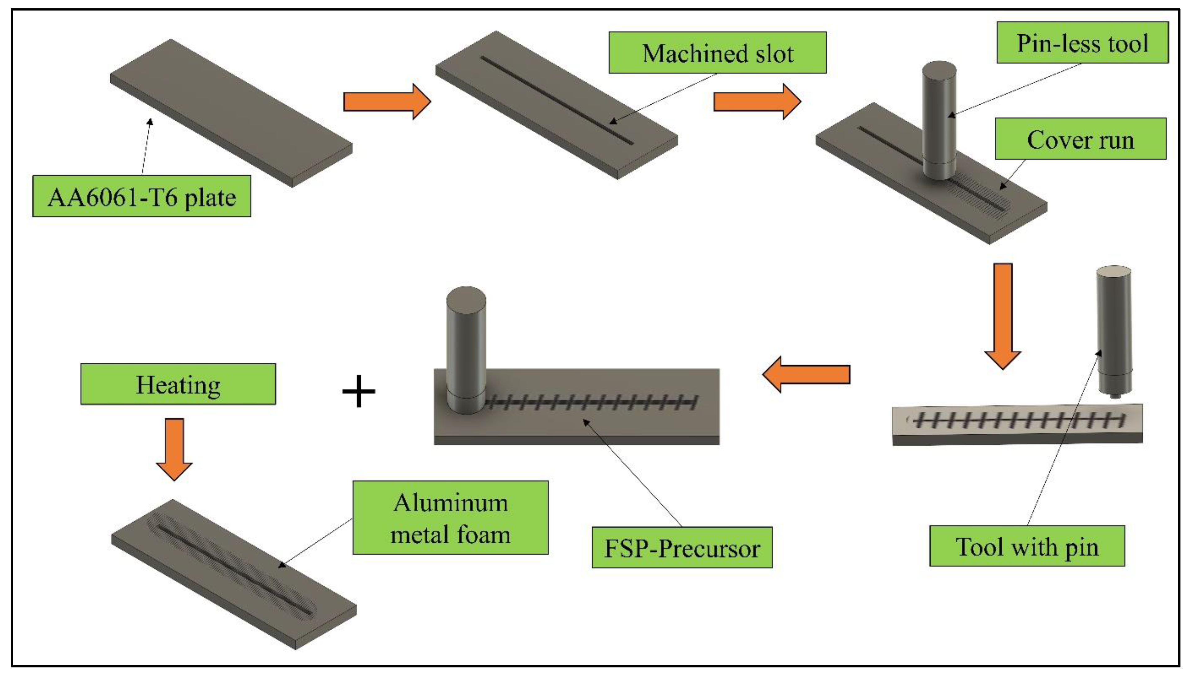
AA6061-T6, as received aluminium alloy plates having dimensions of 200 mm × 60 mm × 8 mm, were used as the base material (BM). The weight percentage of the major alloying elements is enlisted in
Table 1. A slot 2 mm in width, 2.5 mm in depth, and 180 mm in length was machined at the centre of the plate with a CNC vertical machine. The slot was filled with MgCO
3 powder blowing (10 µm particle size), and 2.5 g powder was packed in the slots by a screw press. A pinless tool with a 12 mm shoulder diameter was used to cover the slot packed with a blowing agent. The precursor was prepared by performing FSP on a robust retrofitted vertical milling machine.
Figure 1 illustrates the different steps involved in FSP. An H13 tool with a pin length of 4 mm was used to carry out the FSP. The tool tilt angle and plunge depth were also kept at 2° and 4.2 mm, respectively. To analyse the combined effect of tool-rotational speed, traverse speed, and shoulder diameter, Taguchi’s L
8 orthogonal array (OA) was employed.
Table 2 represents the parameters utilized in FSP.
In order to study the grain morphology and the distribution of MgCO3, the specimens were obtained from the transverse section of the entire processed zone via a CNC-controlled wire electric discharge machining (make: Concord Corporation, Bengaluru, India, Model: DK7712). The samples were prepared in accordance with the standard metallographic techniques. The samples were etched with a reagent comprising 150 mL distilled water, 13 mL HNO3, 3 mL HF, and 4 mL HCl for 3 min.
All the specimens (precursors) were heated in a muffle furnace (Nabertherm, Lower Saxony, Germany) at 650 °C for 10 min to allow for foaming. Post heat treatment, the decomposition of MgCO3 into Mg and CO2 takes place, creating void spaces. The morphology, structure, and distribution of voids in the metal matrix all significantly depend on the dispersion and density of the foaming agent in the process zone. An optical microscope (make: HD Technologies, Faridabad, India, Model: XJL-17) was used to capture the images of the foamed microstructure.
3. Results and Discussion
Different FSP parameters significantly affect the frictional heat input required for adequate softening, which is essential for effective material flow and transport across the processed zone and, consequently, the distribution of the foaming agent. The stirring of adequately softened material achieves the mixing and distribution of the blowing agent, which is packed in the slot. The amount of heat generation is influenced significantly by tool-rotational speed, shoulder diameter of the tool, and traverse speed [
24,
25]. The distribution of the foaming agent ensures and affects the density, distribution, and structure of pores.
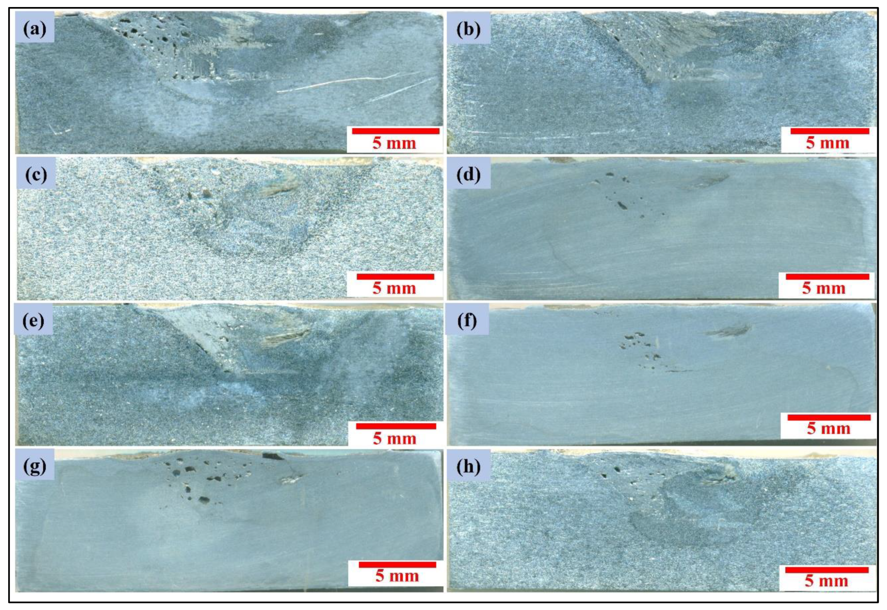
The macrostructures of the specimens corresponding to Experiments 1–8 are shown in
Figure 2. The processed/stir zone (PZ/SZ) of all the samples is demarcated. The SZ of Experiments 1 and 2 (
Figure 2a,b, respectively) are free of any defect and agglomeration which is essential for proper pore morphology and structure. However, the SZ in the rest of the samples showed the presence of either a small tunnelling defect or agglomeration of MgCO
3 particles in small amounts or both on the advancing side (AS).
In fact, the material being stirred is a mix of MgCO
3 particles and a softened Al-alloy matrix. Softening is more significant at a higher heat input, which depends on the FSP parameters. An increase in rpm and shoulder diameter increases the heat input, and an increase in traverse speed reduces it. The entire material being stirred has a heterogeneous makeup which becomes mixed and dispersed as it is transported due to the rotational and traversing motions of the tool. The degree of softening, stirring action, and material transport significantly affect the cross-sectional area of the PZ and, consequently, the PZ’s volume. This transport of material and simultaneous mixing also subdivides the particles and spreads and distributes them to a more homogeneous makeup [
25]. If the matrix is too soft, then the MgCO
3 particles (which are otherwise discrete and loose) cling to the matrix intimately, and the particle agglomeration will increase. On the other hand, if the softening is not enough, then the particles which are discrete and loose will cling less intimately to the matrix leading to poor interfacial bonding, but the dispersion will be better. It can be observed that the SZ in Experiments 5 (
Figure 2e) and 6 (
Figure 2f) show minimal agglomeration in comparison to Experiments 3, 4, 7, and 8. The experiments performed at lower rotational speed within the selected range (i.e., 900 rpm) showed little or no defect and agglomeration. This may be attributed to: (a) adequate heat input, (b) the stirring is able to adequately mix and transport the matrix–particle mix more evenly and adequately. It can be noted that an increase in shoulder size introduced agglomeration and defects. Increased shoulder size on the one hand increases the heat input but also enhances the volume fraction of the softer matrix. This makes material transport and particles’ dispersion difficult, resulting in defects and agglomeration. Further, the material which is present ahead of the tool in the AS is transported and becomes settled behind the tool on the AS [
26]. Consequently, the material in the front of the tool has to undergo large displacement, thereby causing material deficiency on the AS [
27]. It is evident from the macrographs that the PZ is more spread out on the RS. This is chiefly attributed to the mechanism of material transport from AS to RS, which consequently leads to an increase in induced strains on RS. The shape of PZ and the dispersion of foaming particles significantly influence the amount of foaming.
Evidently, the FSP process parameters have a significant effect, and some parameters produce mutually contradictory effects on the spreading out of MgCO
3 within the PZ. A single composite parameter, ‘unit stirring’, which is representative of stirring action, the area of the PZ and the rate of processing, etc., may be more useful. The unit stirring was used to evaluate the combined effect of rotational speed (
n), traverse speed (
v), and shoulder diameter (
ds) [
25]. The unit stirring is represented by Equation (2) and refers to the length of the material processed per shoulder diameter in one tool rotation.
Table 3 provides estimates of the unit stirring, the area of the processed cross-section, i.e., PZ, and the rate of the PZ volume processed per minute. Experiments 1–4 and Experiments 5–8 were performed with a tool having shoulder diameters of 16 mm and 18 mm, respectively. Experiments 1–4 resulted in an average unit stirring = 7.03, and there exists an inverse relationship between unit stirring and PZ area (the average PZ area was estimated to be = 53 cm
2), giving a 7.54 cm
2 average PZ area per average unit stirring. Experiments 5–8 resulted in an average unit stirring = 6.26 and an average PZ area = 42.11 cm
2. For Experiments No. 5–8, the PZ area was found to increase with an increase in unit stirring, and this set of experiments provided a 6.72 cm
2 average PZ area per average unit stirring. This leads to the inference that a 20% increase in average unit stirring resulted in a 12% increase in the average PZ area.
It can be observed that for Experiments 1–4, the average PZ volume processing rate is 70 cm3/min at an average unit stirring value of 7.03 (equivalent to 9.95 cm3/min-unit stirring). Further, for Experiments 5–8, the average PZ volume processing rate is 86.91 cm3/min, an average value of unit stirring = 6.26 (equivalent to 6.72 cm3/min-unit stirring).
The macroscopic bulk estimates, as presented in the foregoing sections, confirm the microscopic analysis of the particle distribution, which consequently reflects on the foaming.
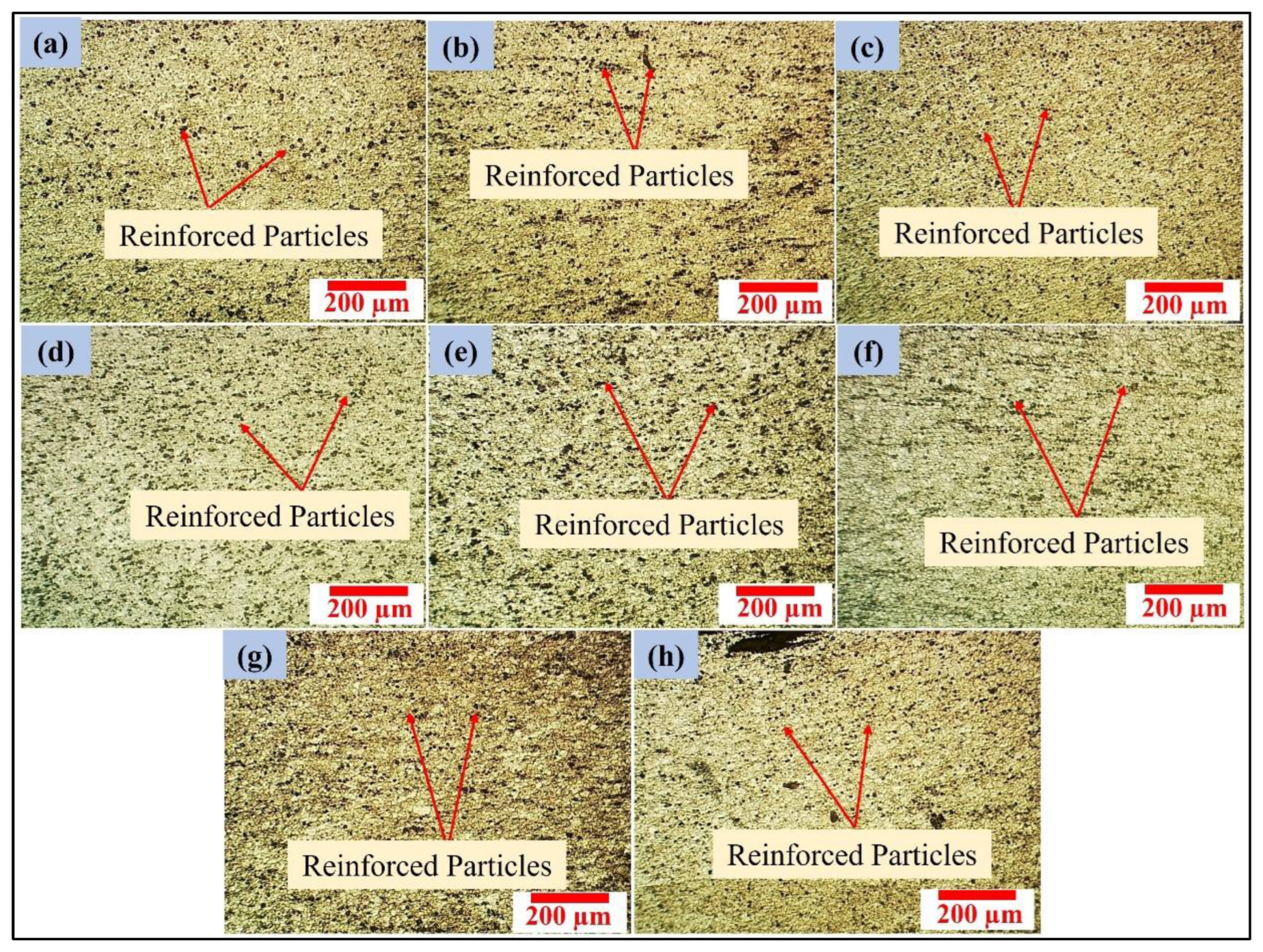
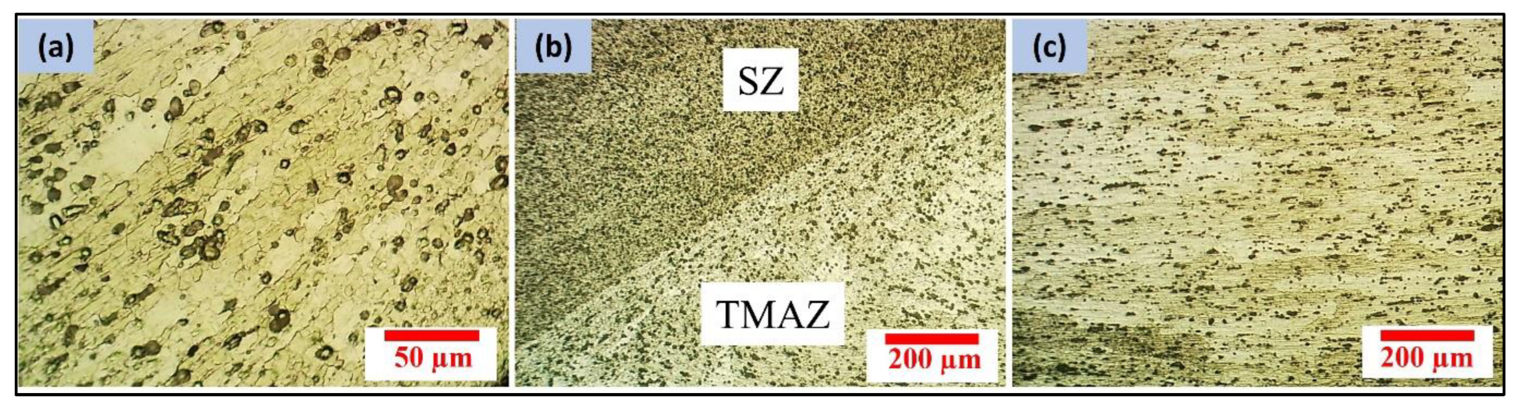
Figure 3 captures the micrographs of PZ corresponding to all the precursors (FSP samples), while
Figure 4 shows the microstructure of thermo-mechanical affected zones (TMAZ) and heat affected zones (HAZ) from one of the experiments. The frictional heating and stirring by the tool generate a peculiar thermal profile and materials flow that is evident in the form of characteristic zones [
28]. The PZ is directly stirred by the tool and undergoes dynamic recrystallization (DRX). The TMAZ undergoes lower strain rates and induced strains at a temperature lower than PZ. The HAZ is subjected to only heat cycles and does not receive any foaming particles. Thus, if the stirring is effective, the distribution of particles may reach up to TMAZ, and the foaming may extend up to TMAZ as well. It is evident from
Figure 4 that the matrix grains are larger, and the MgCO
3 particles are also bigger in the TMAZ.
The average grain size of SZ calculated for each FSP specimen and measured by the line intercept method ranges from 6.72 µm to 10.16 µm, indicating a noteworthy effect of FSP parameters on grain size. The smaller the grain size, the finer will be the subdivision of the MgCO
3 particles as well. This behaviour may be attributed to the combined effect of stirring action by the tool rotational speed, heat input, and pinning effect offered by MgCO
3 particles. The variation in the distribution of MgCO
3 particles in different experiments is evident from the micrographs. The micrographs from one of the experiments showing TMAZ and its interface with the PZ and HAZ is represented in
Figure 4 to indicate that grains and particle morphologies in these zones of all the experiment samples are similar. The grains’ size is larger, the particles are bigger, and the distribution density of the particles is also lower.
The PZ microstructural analysis indicates that the foaming agent’s dispersion and distribution are good and homogeneous. Better dispersion and distribution are essential for effective foaming. The FSP specimens were subsequently subjected to post-heat treatment to initiate the decomposition of blowing agent MgCO
3 as per Equation (1). The CO
2 gas produced during the decomposition reaction generates the pores in the matrix near the melting temperature (
Figure 5). An observation of the macrographs in
Figure 5 indicates the presence of a disparity in the size and concentration of the pores. The higher concentration of the pores is mainly on the AS of the PZ. Variation in the size of the pores relates to the degree of dispersion of the foaming agent (MgCO
3 particles) in the matrix phase. The large size indicates that the mixing and dispersion of the MgCO
3 particles within the matrix are not adequate. Even larger sizes (such as in
Figure 5d,f,g) may also indicate particle agglomeration in small patches.
It is evident that the macro- and microstructural analyses of the precursor, as well as the morphology of particle distribution, correlate with the resultant foaming. It is worthwhile to quantify the porosity and relate it to the composite FSP parameter, i.e., unit stirring. The porosity percentage (
p%) in the specimens was calculated using Equation (3), and the density was computed as per the Archimedes principle.
where
ρi and
ρf are the densities of the specimens before and after the heat treatment process, respectively. The samples for measuring bulk density 20 mm long through thickness samples having a width equal to shoulder diameter for precursor and foamed samples were both removed through wire electric discharge machining. The measured values of porosity are given in
Table 4.
In addition to coarse data based on average values, an analysis based on process parameters indicates that foamed samples that underwent FSP at low rotational speed (900 RPM) showed high porosity except for Experiment 4. The macrographs in
Figure 5 and
Figure 6 show a cluster of pores on the AS of PZ of all samples. The transport of material during stirring causes a lot of churning and mixing, and the MgCO
3 particles undergo mixing and distribution [
29]. Further, the stirring by the tool shears the material and applies forging pressure to push the material behind it on the RS. This mechanism leads to a disparity in forces on both sides [
26]. Consequently, the pore morphology is different on both sides.
An analysis reveals that the average porosity for Experiments No 1–4 was 13.54% (average unit stirring = 7.03 providing an average porosity of 1.93%/average unit stirring). Furthermore, the average porosity for Experiments 5–8 was 11.68% at an average unit stirring of 6.26 (it results in an average porosity of 1.87%/average unit stirring). The average pore sizes for Experiments 1–8 were obtained as 10.5 µm, 15.1 µm, 17.1 µm, 15.7 µm, 15.6 µm, 17.8 µm, 12.5 µm, and 12.8 µm, respectively. The pores are round and have a close cell structure. The wide variations in the pore size indicate that the size closely depends on the FSP parameters employed for the distribution of the foaming agent.
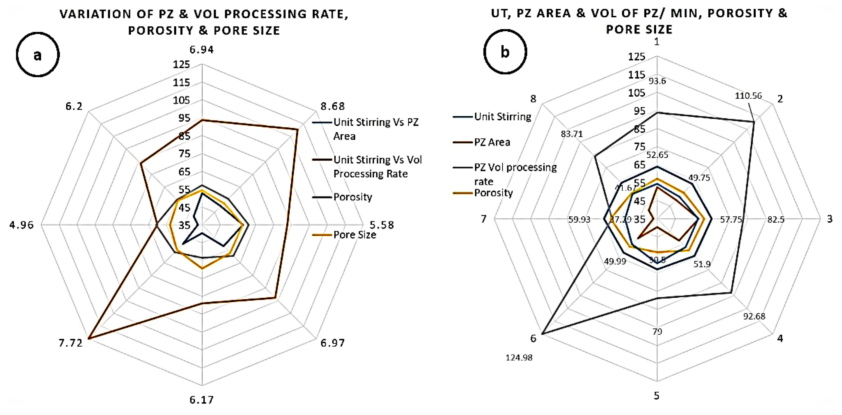
Relating response factors with the FSP parameters are essential in explaining the evolution of micro- and macrostructural morphologies. However, from the point of view of devising an effective process, attaining good foaming is the ultimate aim. In line with this, the numeric values of process parameters and response factors, when plotted on the polar system by the Kiviat diagram (
Figure 7), provide vital and interesting facts. The contradicting nature of FSP parameters provides a segmented relationship with responses, making interpretation difficult. The polar representation of information simplifies the interpretation.
It can be observed that, whereas the unit stirring vs. the PZ area as well as the unit stirring vs. the volume processing rate of PZ is segmented (
Figure 7a), the values of both these responses are symmetrical around the opposite sides of the polar axis. This helps in selecting the desired PZ area and the volume processing rate of PZ via the unit stirring parameter. An even more interesting and important point is that the pore size and pore density both are symmetrically distributed about the unit stirring (
Figure 7a,b). This emphasizes the unit stirring parameter’s importance and usefulness in obtaining adequate pore size and density.
The variation in pore size is attributed to the nature of mixing and dispersion of the blowing agent in the substrate. The pore size does not have a discernible impact on the porosity of the samples. However, it greatly affects the mechanical properties of the foam, such as plateau stress and energy absorption. Keeping the pore size small results in a higher number of pores; thereby, the foams produced have a low edge thickness. As a result, there is insufficient energy, which impairs the mechanical properties. The large pores result in a non-homogenous dense structure, which decreases the plateau stress [
30].


 ,
, 


