Abstract
In this study, the nano-multilayer film was prepared by alternating deposition of MoS2/Ti composite layer and amorphous C layer, and the irradiation damage effect was studied by the heavy ion bombardment experiment of 2 MeV Au2+. The results show that the irradiation region of the film is about 500 nm deep. The MoS2 crystal inside the MoS2/Ti composite layer in the irradiation-affected area is destroyed by incident Au2+ ions and turns into a disordered state. With the increase of irradiation dose, the hardness of the film increases from 1.58 to 3.28 GPa, and the wear life of the film decreases sharply from 3 × 10⁴ to 5 × 10³ r due to the destruction of the internal crystal and the embrittlement of the structure. In addition, with the increase of irradiation dose, the interlayer interface is gradually blurred and the interlayer diffusion is gradually aggravated.
1. Introduction
Nuclear fusion reactions provide near-limitless energy cleanly and safely [1]. Magnetic confinement nuclear fusion produces energy by confining high temperature and high-density deuterium-tritium plasma discharge with a strong magnetic field. Lubrication materials of moving parts used in magnetic confinement fusion devices not only face friction and wear, but also withstand high and low temperature, vacuum, and radiation environments of fusion devices. In an extreme irradiation environment induced by an advanced nuclear reactor, there would be a large number of spot defects, such as gap atoms and vacancies in the nuclear materials [2,3,4]. The accumulation of point defects form clusters, voids, and other large defects, leading to swelling [5], creep, hardening [6], embrittlement [7], and other phenomena of the material, which further degrade and fail the material’s performance. The development of lubrication coatings for applications in harsh environments can ensure the normal operation of equipment and predict its service life for better maintenance of equipment [8,9,10,11].
A large number of studies have shown that grain boundaries, phase boundaries, and free surfaces can be effective sinks for point defects [12,13,14,15]. Bai et al. found that grain boundaries are effective sinks for both gap atoms and vacancies through loading and unloading effects [16]. Multilayer nanocomposite films, such as Cu/Nb [17], Cu/W [18], Fe/Ni [19], Fe/W [20], etc., have interfaces that can capture a large number of vacancy and gap atoms and promote their recombination. In addition, amorphous intergranular film and amorphous/amorphous multilayer film have more unique grain boundary structures. The former can improve the stability of crystal size inside the crystalline layer, while the latter can avoid the formation of traditional crystal defects, which is more suitable for application in an irradiation environment than traditional crystal materials [21,22,23].
This study contains a kind of MOST/C nano-multilayer film (MOST: MoS2 and Ti co-sputtering; C is an amorphous layer). Its properties and structural response under 2 MeV Au2+ ion irradiation were studied (Heavy ion irradiation can produce radiation damage effect similar to high-energy neutrons in a fusion reactor, and can avoid the shortcomings of neutron irradiation such as its long duration, the radioactivity of samples, and uncontrollable conditions), to explore whether the interface and amorphous C layer play a theoretical role in the film. At the early stage of the experiment, the lubrication performance of multilayer films was regulated by changing the ratio of the MOST layer to the C layer to achieve the appropriate experimental level. MoS2 films were selected as the material because they are considered to be the best choice for fusion reactor applications due to their excellent lubrication properties [24,25,26,27,28]. To ensure that the addition of the C layer can maintain its lubrication performance, the Ti element was added to prepare the MOST film.
2. Materials and Methods
2.1. Film Deposition
The film is deposited by magnetron sputtering, and the MoS2/Ti composite layer (MOST: MoS2 and Ti co-sputtering) and the C layer are deposited alternately on the surface of the Si substrate by manipulating the baffle. Before the film deposition, the Ti transition layer with a thickness of about 200 nm was preferentially deposited to enhance the film-base binding property. The film deposition parameters are as follows: Ar+ gas is fed into the chamber before the deposition to control the pressure of 0.65 Pa; MoS2-250 W, Ti-0.11 A, MOST thickness is about 30 nm; C-400 W thickness is about 10 nm; Sputtering process cycle 25 times; The top layer is the MOST layer to ensure initial lubrication performance.
2.2. Heavy Ion Irradiation
Ion irradiation experiments on the surface of films were performed on 2 × 1.7 MeV tandem accelerators in the ion beam materials laboratory (IBML) at Peking University, China. The films were irradiated with 2 MeV Au2+ ions at an influence of 1.0 × 10¹⁴, 3.3 × 10¹⁴, 6.6 × 10¹⁴, and 1.65 × 10¹⁵ ions/cm2 which corresponded to the serial number of MC1, MC2, MC3, and MC4. The experiments were achieved at room temperature, the incident angle of Au2+ beams was perpendicular to the film’s surface, and the current of incidence beams was in a range of 100 to 200 nA.
2.3. Structural and Properties Characterization
Grazing incident X-ray diffraction (GIXRD, D8 Advance, Bruker, Karlsruhe, Germany) characterized the crystal structure of the film with a 2° incidence angle to ensure that the entire irradiated region could be scanned. GIXRD measurements used copper Kα radiation, and diffraction patterns were obtained from 10° to 80°. Horiba LabRAM HR800 micro confocal Raman spectroscopy (HORIBA Jobin Yvon, Paris, France) was used for surface testing. The excitation wavelength was 532 nm and the laser power was 5%, to prevent the film from burning due to high laser power. The integration time parameter was 60 s/2 times, and multiple different areas were selected for each sample to test to ensure the accuracy of data. X-ray energy dispersive spectroscopy (EDS, JEOL, Tokyo, Japanese) was used to analyze the changes of elements on the film surface before and after irradiation. TEM testing was conducted using a transmission electron microscope (TECNAI G2 S-TWIN F20, FEI, Hillsboro, OR, USA) to observe the sample’s cross-section and collect the sample’s electron diffraction pattern. The operating voltage was 200 kV. TEM samples were prepared by focused ion beam cutting (FIB) with a cross-section thickness of about 100 nm.
Nano indenter (TI950, Hysitron TriboIndenter, Minneapolis, MN, USA) with Berkovich diamond tip was used to evaluate the hardness and elastic modulus of the film before and after ion irradiation. To exclude the influence of substrate, the indentation depth was controlled at about 10% of the film thickness. Under a vacuum environment (≤5.0 × 10⁻⁴ Pa) with a normal load of 3.0 N and rotation speed of 1000 r/min, the films’ friction and wear properties were evaluated using a self-made ball-disc tribometer. The disc was a Si substrate with the film deposited, and the dual ball was AISI 440C steel ball (diameter 8 mm, Ra ≤ 0.1 μm). The wear life of the film was defined as the sliding cycle before the friction coefficient ≥ 0.15.
3. Results
SRIM software was used to simulate the bombardment process of heavy ions for MOST/C nano-multilayer films before the irradiation experiment, as shown in Figure 1 [29]. In the simulation process, the Au2+ ion beam focused on a point on the surface of the film and injected into the film. To show the irradiated area more clearly, only a film with 15 cycles was set up in the simulation. As can be seen from the figure, the influence width of irradiation was about 160 nm, and the depth was 470~510 nm. After the incident, Au2+ ions were mainly deposited in the depth of 270~440 nm, and the damage peak was about 300 nm. The presence of the C layer had little effect on the depth of Au2+ ions entering the film [30]. The impact of ion bombardment on the near-surface region of the film was less than that in the interior. After ions were injected into the film, the phenomenon of collision and cascade occurred inside the thin film, resulting in a large number of damage defects [31].
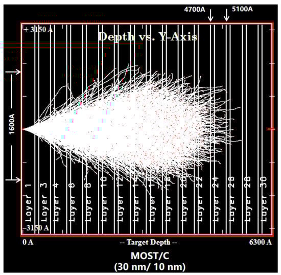
Figure 1.
SRIM irradiation simulation results of MOST/C nano-multilayer films (mode: ion distribution and quick calculation of damage).
Figure 2 shows the XRD patterns and Raman spectra of MOST/C nano-multilayer films before and after irradiation. It can be seen from the figure that there are two diffraction peaks (002) and (100) in the film before irradiation, and the peak intensity of the latter is higher than that of the former, indicating that the internal grains of the film mainly grow in the orientation perpendicular to the substrate (100) [32]. In Figure 2b, the film before irradiation has two typical vibration peaks of MoS2 film, E12g and A1g, near 400 cm−1 [33]. In addition, since the top layer is the MOST layer and the laser power needs to be controlled to avoid burning the film, the signal of layer C cannot be detected in the Raman characterization. After irradiation, the XRD pattern and Raman spectrum peaks of the film disappear, indicating that the internal grains of the film were destroyed and transformed into amorphous states. The peak of irradiated film MC1 (irradiation dose is 1 × 10¹⁴ ions/cm2) disappeared, indicating that the film had poor anti-irradiation performance. It can be found from here that the structure had little influence on the stability of the internal crystal structure of MoS2 composite film under an irradiation environment.
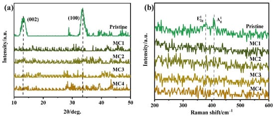
Figure 2.
XRD patterns (a) and Raman spectra (b) of MOST/C nano-multilayer films before and after irradiation.
An EDS test was conducted on the surface composition of the film before and after irradiation, and the results are shown in Table 1. The data show that the O content of the film surface is high, which is mainly due to the absorption of water in the air by the film surface during the storage process. This is related to the surface properties of MoS2 [34]. This process is called physical adsorption; water molecules can be desorbed in a variety of ways. By comparing the data of irradiated samples, it can be found that both the content of the O element and the ratio of S/Mo on the surface of the film show a decreasing trend. The former is mainly due to the desorption of the O element during the experiment. The latter is due to the increase of S vacancies on the surface of the film with the increase in irradiation dose [35].

Table 1.
The chemical compositions of the film before and after irradiation.
After the growth state and composition characterization of the films, the microstructure of the films was observed by TEM, as shown in Figure 3. The figure shows the cross-section image of the pristine film and the locally enlarged image, and the Fast Fourier transform of the red box region in Figure 3b,d [36]. In the figure, it can be found that the thickness of the MOST layer of the pristine film is about 30 nm, and it has an amorphous/crystal composite structure. Due to the influence of the C layer (which is not conducive to the nucleation growth of MoS2 crystal), the proportion of the amorphous region increases [37]. The C layer is a 10 nm thick amorphous layer. There is an irregular amorphous interface between the two, which further increases the area of the interface.
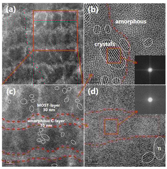
Figure 3.
Cross-section TEM image and local magnification image of the pristine film. (a) cross-section; (b) MOST-layer; (c) (a)-local magnification; (d) C-layer.
Figure 4 shows the cross-section image of the irradiated sample MC4. Region 3 is not affected by irradiation. Regions 1 and 2 correspond to the near-surface region and the damage peak region of the irradiation damage area, respectively [38]. The Figure 4b,c is locally enlarged images of regions 1 and 2, respectively. According to the enlarged images of different areas, the film shows a completely disordered state after irradiation, which is consistent with the previous XRD characterization results. The intergranular amorphous C layer and irregular interface do not give the film anti-irradiation ability, and the stability of the MoS2 crystal is still poor. In addition, through the comparison of the thickness of each layer in different areas, it is found that the deeper into the film, the more blurring of the interface between the MOST layer and the C layer, and the more serious the diffusion of the C layer to the MOST layer (C diffuses more easily than MoS2 under irradiation), as shown in Figure 4d.
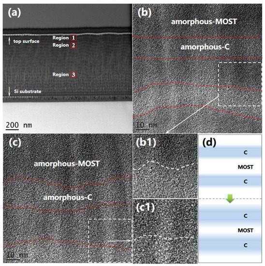
Figure 4.
Cross-section TEM image (a) and local magnification image of the irradiated film: region 1-(b,b1); region 2-(c,c1); (d) corresponds to a simplified graph of (b,c).
For more obvious observation, the areas under different injury degrees were compared. As shown in Figure 5, (a) is the cross-section image of the irradiation region; (b,b1) is the cross-section image of the area where the damage degree is about 2 displacement per atom (dpa); (c,c1) is the cross-section image of the area with a damage degree of about 5 dpa. By comparing images of areas with different damage degrees, it can be seen more directly that the diffusion phenomenon of layer C becomes more serious with the increase of irradiation damage degree. After the ions are injected into the film, energy dissipation occurs when they collide with the target atoms, and a collision cascade phenomenon occurs. The free volume of the atoms at the irregular amorphous interface is large, and the occurrence of a collision cascade is easy to make the atoms migrate and diffuse between the layers. In addition, the thermal effect produced by ion bombardment in the film further provides the kinetic energy of atomic motion, so the higher the damage degree (the more serious the bombardment), the more obvious the diffusion phenomenon.
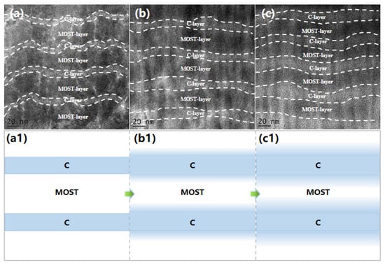
Figure 5.
Cross-section TEM images and its corresponding simplified image of films with different irradiation damage degrees: (a,a1) pristine, (b,b1) 2 dpa, (c,c1) 5 dpa.
The change in the structure of MOST/C nano-multilayer films will inevitably lead to a change in their properties. The test of its anti-irradiation hardening found that its hardness increased with the increase of irradiation dose because the structure and internal energy of the film were changed by ion bombardment (Figure 6) [39,40]. However, when the irradiation dose increases from 6.6 × 10¹⁴ to 1.65 × 10¹⁵ ions/cm2, the hardness of the film has little change, indicating that the influence of ions on the internal structure of the film tends to be saturated, and the irradiation hardening parameters of the film fall within this range. The maximum hardness of the pristine film is 2.08 times (1.58~3.28 GPa), an increase of 107.5%. Due to the existence of an amorphous C layer, the hardness of the pristine film is low, which affects the maximum hardness after irradiation. However, the irradiation hardening degree of the film is within the acceptable value range of the film irradiated by MoS2 (the increase is less than 250%) [6,39].
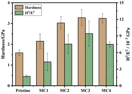
Figure 6.
Hardness and H3/E2 of the MOST/C nano-multilayer before and after irradiation.
Figure 7 shows the changes in film lubrication properties before and after irradiation. It can be seen from the figure that the wear life of the pristine film is about 3 × 10⁴ r, and after irradiation, its wear life is less than 5 × 10³ r, which is 1/6 of the pristine film’s life. The changes in wear life correspond to the structural changes characterized by XRD in Figure 2. The wear lives of MoS2 composite films are related to the internal structure and mechanical properties of the films. The transformation and hardening of the amorphous structures produced by the irradiation experiments are not conducive to the lubrication performance of the films. The inner structure of MOST/C nano-multilayer films changes into a disordered state at a small irradiation dose (1 × 10¹⁴ ions/cm2, MC1), resulting in a sharp decline in wear life. With the increase of irradiation dose, the hardening caused by irradiation began to make the film brittle and affected the lubrication performance of the film. Although the hardness of MC3 and MC4 films is similar, the plastic deformation resistance (H3/E2) of the latter is weaker than that of the former, indicating that its brittleness is higher, so that the latter wear life test value is lower.
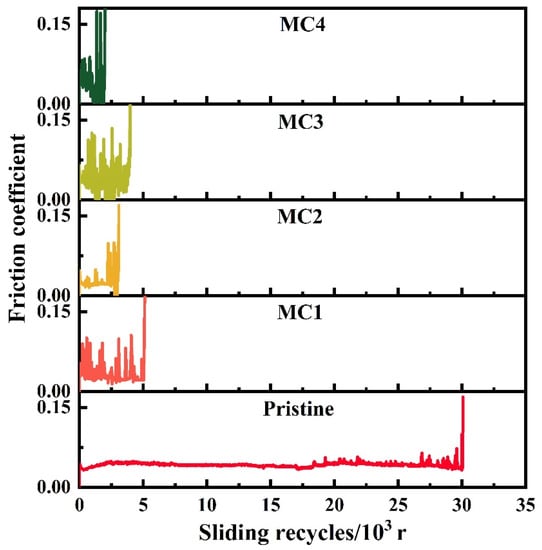
Figure 7.
The wear lives of the multilayer films before and after irradiation.
4. Conclusions
In this study, the irradiation response and properties of MOST/C nano-multilayer films were investigated by Au2+ ion irradiation experiments. The simulation found that the depth of influence of ion bombardment was about 500 nm. It also causes the desorption of O elements and the increase of S vacancy on the film surface. TEM images of the cross-section of the irradiated film show that the MoS2 crystal in the MoS2/Ti composite layer is destroyed under the bombardment of Au2+ ions, and then transformed into an amorphous layer. In addition, the phenomenon of interlayer diffusion appears in the irradiation process, which is aggravated with the increase of irradiation dose, indicating that this phenomenon is caused by the bombardment of Au2+ ions, and the atoms in the amorphous state are more prone to transfer. After the irradiation experiment, there was an obvious phenomenon of irradiation hardening; due to the change of internal energy and density, the hardness of the film increased from 1.58 to 3.28 GPa, an increase of 107.5%. The wear life of the film also reduced from 3 × 10⁴ to 5 × 10³ r due to the destruction of MoS2 crystal and the high hardness (to make the film brittle) of the film. The amorphous intergranular layer and irregular interface in this structure design did not bring the theoretical irradiation resistance of MoS2-based composite films.
Author Contributions
Conceptualization, P.W.; methodology, L.Q. and R.Z.; validation, R.Z. and H.Z.; investigation, P.W., L.Q., R.Z. and H.Z.; resources, P.W. and L.Q.; writing-original draft preparation, R.Z.; writing-review and editing, P.W. and R.Z.; visualization, P.W. and R.Z.; supervision, P.W. and L.Q.; funding acquisition, P.W. All authors have read and agreed to the published version of the manuscript.
Funding
Authors acknowledge the financial assistance of the National key R&D project of China with project number 2022YFB3809000 and the National Natural Science Foundation of China (Grant No: 52205235).
Institutional Review Board Statement
Not applicable.
Informed Consent Statement
Not applicable.
Data Availability Statement
The data that support the findings of this study are available from the corresponding author upon reasonable request.
Conflicts of Interest
The authors declare no conflict of interest.
References
- Pfeiffer, B.; Mulder, P. Explaining the diffusion of renewable energy technology in developing countries. Energy Econ. 2013, 40, 285–296. [Google Scholar] [CrossRef]
- Arakawa, K.; Imamura, R.; Ohta, K.; Ono, K. Evolution of point defect clusters in pure iron under low-energy He+ irradiation. J. Appl. Phys. 2001, 89, 4752–4757. [Google Scholar] [CrossRef]
- Hopf, C.; Jacob, W.; Keudell, A.V. Ion-induced surface activation, chemical sputtering, and hydrogen release during plasma-assisted hydrocarbon film growth. J. Appl. Phys. 2005, 97, 094904. [Google Scholar] [CrossRef]
- Zhu, X.; Zhang, Y.; Cheng, L.; Yuan, Y.; Temmerman, G.D.; Wang, B.; Cao, X.; Lu, G. Deuterium occupation of vacancy-type defects in argon-damaged tungsten exposed to high flux and low energy deuterium plasma. Nucl. Fusion 2016, 56, 036010. [Google Scholar] [CrossRef]
- Zinkle, S.J.; Was, G.S. Materials challenges in nuclear energy. Acta Mate. 2013, 61, 735–758. [Google Scholar] [CrossRef]
- Zhang, R.; Yun, P.; Zhang, H.; Wang, P. Control of the irradiation-resistant structure inside MOST films by heat effect. Appl. Surf. Sci. 2022, 605, 154622. [Google Scholar] [CrossRef]
- Chopra, O.K.; Rao, A.S. A review of irradiation effects on LWR core internal materials—Neutron embrittlement. J. Nucl. Mater. 2011, 412, 195–208. [Google Scholar] [CrossRef]
- Wahl, K.J.; Dunn, D.N.; Singer, I.L. Effects of ion implantation on microstructure, endurance and wear behavior of IBAD MoS2. Wear. 2000, 237, 1–11. [Google Scholar] [CrossRef]
- Josseaume, F.; Cordier, J.; Cuquel, B.; Guirao, J.; Hovine, B.; Tonqueze, Y.L.; Levesy, B.; Martins, J.P. Development and qualification of the ITER port plug handing process. Fusion Eng. Des. 2018, 136, 902–907. [Google Scholar] [CrossRef]
- Hillairet, J.; Chen, Z.; Lombard, G.; Delaplanche, J.M.; Vulliez, K.; Yang, Q.; Beaumont, B.; Calarco, F.; Charabot, N.; Kazarian, F.; et al. Radiofrequency and mechanical tests of silver coated CuCrZr contacts for the ITER ion cyclotron antenna. Fusion Eng. Des. 2018, 129, 29–39. [Google Scholar] [CrossRef]
- Kim, B.Y.; Ahn, H.J.; Bak, J.S.; Choi, C.H.; Ioki, K.; Zauner, C. Lubricant coating of dowel for the ITER vacuum vessel gravity support. Fusion Eng. Des. 2012, 87, 1079–1084. [Google Scholar] [CrossRef]
- Hong, M.Q.; Ren, F.; Wang, Y.Q.; Zhang, H.X.; Xiao, X.H.; Fu, D.J.; Yang, B.; Jiang, C.Z. Size-dependent radiation tolerance and corrosion resistance in ion irradiated CrN/AlTiN nanofilms. Nucl. Instrum. Methods Phys. Res. Sect. B 2015, 342, 137–143. [Google Scholar] [CrossRef]
- Demkowicz, M.J.; Hoagland, R.G.; Hirth, J.P. Interface structure and radiation damage resistance in Cu-Nb multilayer nanocomposites. Phys. Rev. Lett. 2008, 100, 136102. [Google Scholar] [CrossRef] [PubMed]
- Chimi, Y.; Iwase, A.; Ishikawa, N.; Kobiyama, M.; Inami, T.; Okuda, S. Accumulation and recovery of defects in ion-irradiated nanocrystalline gold. J. Nucl. Mater. 2001, 297, 355–357. [Google Scholar] [CrossRef]
- Pérez-Pérez, F.J.; Smith, R. Structural changes at grain boundaries in bcc iron induced by atomic collisions. Nucl. Instrum Meth. B 2000, 164, 487–494. [Google Scholar] [CrossRef]
- Bai, X.M.; Voter, A.F.; Hoagland, R.G.; Nastasi, M.; Uberuaga, B.P. Efficient Annealing of Radiation Damage Near Grain Boundaries via Interstitial Emission. Science 2010, 327, 1631–1634. [Google Scholar] [CrossRef] [PubMed]
- Demkowicz, M.; Bellow, P.; Wirth, B. Atomic-scale design of radiation-tolerant nanocomposites. Mater. Res. Bull. 2010, 35, 992–998. [Google Scholar] [CrossRef]
- Dong, L.; Zhang, H.; Amekura, H.; Ren, F.; Chettah, A.; Hong, M.; Qin, W.; Tang, J.; Hu, L.; Wang, H.; et al. Period-thickness dependent responses of Cu/W multilayered nanofilms to ions irradiation under different ion energies. J. Nucl. Mater. 2017, 497, 117–127. [Google Scholar] [CrossRef]
- Chen, F.; Tang, X.; Yang, Y.; Huang, H.; Liu, J.; Li, H.; Chen, D. Atomic simulations of Fe/Ni multilayer nanocomposites on the radiation damage resistance. J. Nucl. Mater. 2016, 468, 164–170. [Google Scholar] [CrossRef]
- Li, N.; Fu, E.G.; Wang, H.; Carter, J.J.; Shao, L.; Maloy, S.A.; Misra, A.; Zhang, X. He ion irradiation damage in Fe/W nanolayer films. J. Nucl. Mater. 2009, 389, 233–238. [Google Scholar] [CrossRef]
- Kim, I.; Jiao, L.; Khatkhatay, F.; Martin, M.S.; Lee, J.; Shao, L.; Zhang, X.; Swadener, J.G.; Wang, Y.Q.; Gan, J.; et al. Size-dependent radiation tolerance in ion irradiated TiN/AlN nanolayer films. J. Nucl. Mater. 2013, 441, 47–53. [Google Scholar] [CrossRef]
- Schuler, J.D.; Grigorian, C.M.; Barr, C.M.; Boyce, B.L.; Hattar, K.; Rupert, T.J. Amorphous intergranular films mitigate radiation damage in nanocrystalline Cu-Zr. Acta Mater. 2020, 186, 341–354. [Google Scholar] [CrossRef]
- Huang, L.; Chen, Z.Q.; Liu, W.B.; Huang, P.; Meng, X.K.; Xu, K.W.; Wang, F.; Lu, T.J. Enhanced irradiation resistance of amorphous alloys by introducing amorphous/amorphous interfaces. Intermetallics 2019, 107, 39–46. [Google Scholar] [CrossRef]
- Christoph, Z.; Reindl, M.; Robin, L.B.; Choi, C.H.; Ahn, H.J. Mechanical testing of the ITER vacuum vessel support structure-coating screening tests and high load multi-axial Mock Up tests. Fusion Eng. Des. 2014, 89, 1804–1808. [Google Scholar] [CrossRef]
- Lingertat, J.; Gradt, T.; Hathiramani, D.; Junghanns, P.; Laux, M.; Meine, K.; Schauer, F.; Schneider, T. Tribological performance of MoS2 coatings in liquid helium and at high loads. Fusion Eng. Des. 2009, 84, 1192–1196. [Google Scholar] [CrossRef]
- Gradt, T.; Schneider, T.; Lingertat, J.; Hathiramani, D.; Junghanns, P. Cryogenic vacuum tests of scaled-down narrow support elements for the W7-X coil system. Fusion Eng. Des. 2009, 84, 840–843. [Google Scholar] [CrossRef]
- Koch, F.; Nocentini, R.; Heinemann, B.; Lindig, S.; Junghanns, P.; Bolt, H. MoS2 coatings for the narrow support elements of the W7-X nonplanar coils. Fusion Eng. Des. 2007, 82, 1614–1620. [Google Scholar] [CrossRef]
- Shi, S.; Song, Y.; Cheng, Y.; Villedieu, E.; Bruno, V.; Feng, H.; Wu, H.; Wang, P.; Hao, Z.; Li, Y.; et al. Conceptual design main progress of EAST Articulated Maintenance Arm (EAMA) system. Fusion Eng. Des. 2016, 104, 40–45. [Google Scholar] [CrossRef]
- Ziegler, J.F.; Ziegler, M.D.; Biersack, J.P. SRIM-the stopping and range of ions in matter. Nucl. Instrum. Methods Phys. Res. B 2010, 286, 1818–1823. [Google Scholar] [CrossRef]
- Duan, Z.; Zhao, X.; Qiao, L.; Zhao, Y.; Fu, E.; Wang, P.; Liu, W. Structural evolution and wear resistance of MoS2 –Based lubricant films irradiated by heavy ions. Surf. Coat. Tech. 2019, 378, 125077. [Google Scholar] [CrossRef]
- Yang, T.; Huang, X.; Gao, Y.; Wang, C.; Zhang, Y.; Xue, J.; Yan, S.; Wang, Y. Damage evolution of yttria-stabilized zirconia induced by He irradiation. J. Nucl. Mater. 2012, 420, 430–436. [Google Scholar] [CrossRef]
- Fleischauer, P.D.; Lince, J.R. A comparison of oxidation and oxygen substitution in MoS2 solid film lubricants. Tribol. Int. 1999, 32, 627–636. [Google Scholar] [CrossRef]
- Krishnan, U.; Kaur, M.; Singh, K.; Kumar, M.; Kumar, A. A synoptic review of MoS2: Synthesis to applications. Superlattices Microstruct. 2019, 128, 274–297. [Google Scholar] [CrossRef]
- Zhou, H.; Zheng, J.; Wen, Q.; Wan, Z.; Sang, R. The effect of Ti content on the structural and mechanical properties of MoS2/Ti composite coatings deposited by unbalanced magnetron sputtering system. Phys. Procedia 2011, 18, 234–239. [Google Scholar]
- Xiong, G.; Zhu, H.; Wang, L.; Fan, L.; Zheng, Z.; Li, B.; Zhao, F.; Han, Z. Radiation damage and abnormal photoluminescence enhancement of multilayer MoS2 under neutron irradiation. J. Phys. Condens. Matter 2022, 34, 055701. [Google Scholar] [CrossRef] [PubMed]
- Zeng, Y.; Liu, Z.; Wu, W.; Xu, F.; Shi, J. Combining scanning electron microscopy and fast Fourier transform for characterizing mesopore and defect structures in mesoporous materials. Micropor. Mesopor. Mat. 2016, 220, 163–167. [Google Scholar] [CrossRef]
- Duan, Z.; Qiao, L.; Chai, L.; Xu, J.; Wang, P.; Liu, W. Structure, properties and growth mechanism of a self-assembled nanocylindrical MoS2/Mo-S-C composite film. Appl. Surf. Sci. 2019, 465, 564–574. [Google Scholar] [CrossRef]
- Duan, Z.; Zhao, X.; Xu, J.; Wang, P.; Liu, W. Influence of Ni13+ ions irradiation on the microstructure, mechanical and tribological properties of Mo-S-Ti composite films. Appl. Surf. Sci. 2019, 480, 438–447. [Google Scholar] [CrossRef]
- Zhang, R.; Qiao, L.; Zhang, H.; Gao, X.; Wang, P. Influence of Au2+ ions irradiation on the structure and wear resistance of amorphous MoS2 films. Appl. Surf. Sci. 2022, 583, 152497. [Google Scholar] [CrossRef]
- Huang, Y.; Fan, H.; Zhou, X.; Xue, P.; Ning, Z.; Daisenberger, D.; Sun, J.; Shen, J. Structure and mechanical property modification of a Ti-based metallic glass by ion irradiation. Scr. Mater. 2015, 103, 41–44. [Google Scholar] [CrossRef]


Disclaimer/Publisher’s Note: The statements, opinions and data contained in all publications are solely those of the individual author(s) and contributor(s) and not of MDPI and/or the editor(s). MDPI and/or the editor(s) disclaim responsibility for any injury to people or property resulting from any ideas, methods, instructions or products referred to in the content. |
© 2023 by the authors. Licensee MDPI, Basel, Switzerland. This article is an open access article distributed under the terms and conditions of the Creative Commons Attribution (CC BY) license (https://creativecommons.org/licenses/by/4.0/).