Article

Evaluating the Electrochemical and In Vitro Degradation of an HA-Titania Nano-Channeled Coating for Effective Corrosion Resistance of Biodegradable Mg Alloy

1
Department of Metallurgical and Materials Engineering, Punjab Engineering College, Chandigarh 160012, India
2
Department of Mechanical Engineering, Punjab Engineering College, Chandigarh 160012, India
3
Department of Mechanical Engineering, Jamia Millia Islamia, New Delhi 110025, India
*
Author to whom correspondence should be addressed.
Coatings 2023, 13(1), 30; https://doi.org/10.3390/coatings13010030
Submission received: 27 November 2022 / Revised: 16 December 2022 / Accepted: 20 December 2022 / Published: 24 December 2022
(This article belongs to the Special Issue Multi-Functional Nanostructured Sustainable Coatings)

Abstract

:
Extensive research into magnesium (Mg) alloys highlights their possible applications in the field of biodegradable implants. As magnesium alloys are highly electronegative, it is imperative to tailor their degradation rate for clinical safety. Surface coatings have been widely used for the corrosion protection of Mg alloys, but the presence of spatial defects limits their effectiveness. An innovative and near-defect-free hydroxyapatite (HA)-TiO2 nano-channeled (TNC) coating architecture has been developed on ZM21 Mg alloy in the present study by combining anodization and the sol-gel dip coating technique. The HA-TNC coating positively shifted the Ecorr of ZM21 Mg alloy from −1.38 to −0.61 V. Accordingly, the corrosion current density (Icorr, 5.8 × 10⁻⁶ A/cm2) was suppressed by 53.4 times compared to uncoated ZM21 Mg alloy. The polarization resistance (Rp) and charge transfer resistance (Rct) values are the highest among all other samples, indicating the superior shielding ability of the coating. During in vitro immersion for up to 28 days in simulated body fluid (SBF), the HA−TNC coating maintained the lowest degradation rate and hydrogen evolution rate (HER) of 1.10 ± 0.22 mg/cm2/day and 1.83 ± 0.41 mL/cm2/day, respectively. A compact and structurally stable 2D plate-like HA (Ca/P:1.55), mineralized on HA-TNC-coated ZM21, provides effective shielding against the penetration of aggressive ions with prolonged SBF immersion. The findings of the present study provide a rational design for the development of bioactive ceramic coatings on Mg-based bioimplants.

1. Introduction

Worldwide, millions of people suffer bone fractures every year as a result of diseases and accidents [1]. Due to contemporary work culture, the meager physical routines of humans have resulted in a rising number of skeletal disorders in recent decades [2]. Consequently, research is focused on developing an ideal biodegradable implant offering sufficient mechanical integrity and biocompatibility up until bone-healing time. Magnesium (Mg) has a Young’s modulus (45 GPa) and density (1.74 g/cm3) that is comparable to human cortical bone [3]. Moreover, being an essential trace element for the human body, Mg has attracted researchers’ interest in the field of bone implant applications. However, Mg-based implants with full-scale clinical applications are not yet commercialized since several concerns are still unaddressed regarding Mg and its alloys [4]. Mg is highly reactive in physiological media, leading to rapid physiological degradation. Consequently, the implant’s strength is compromised before bone healing takes place [5]. Meanwhile, rapid degradation causes an abundant release of H2 and high alkalinity, which leads to cell apoptosis and tissue necrosis [6]. Thus, to ensure safe clinical applications, it is essential to limit the degradation rate of Mg alloys. Microstructural modifications or surface coatings have been used extensively to prevent rapid degradation [7]. Surface coatings have an advantage over microstructural modifications; apart from a physical barrier, they serve as a potential stockpile to deliver various essential therapeutic responses [8]. However, coatings are risk-prone due to numerous factors. The evaporation of organic residues leads to inevitable spatial defects in ceramic coatings, such as micropores and cracks [9]. These microchannels are easily penetrated by corrosive media, and corrosion occurs at the interface between the substrate and the coating [10].
Nano-channeled TiO2 coatings have been extensively reported for significant biocompatibility, antimicrobial activity, and osseointegration behavior [11]. The nano-channeled structures serve as anchors to firmly hold the upper secondary coating layers and provide structural stability to the coating system [12,13]. It has been widely accepted that Hydroxyapatite (HA) coatings enhance the surface properties of magnesium alloys by supporting the formation of bone-like apatite on the surface. However, the HA coatings’ performance has always been challenging due to their poor stability on metallic surfaces [14]. An implant can fail catastrophically if the coating fails, leaving the substrate directly exposed to corrosive media.
To address the current challenges, an innovative HA-TNC coating architecture has been developed in the present study. Firstly, a nano-channeled TiO2 (TNC) layer has been applied to facilitate the escape of organic residue without damaging the coating matrix. To prevent contact between SBF and the Mg substrate via nano channels, a HA layer was applied on top of the TNC layer to fill the channels. This study investigates the corrosion resistance and in vitro degradation behavior of HA-TNC-coated ZM21 and compares it with single-layered TNC-coated ZM21 and uncoated ZM21 Mg substrates. The corrosion rate was investigated by linear polarization and electrochemical impedance spectroscopy techniques. The in vitro degradation behavior was characterized by the weight loss, hydrogen evolution rate, and pH change of immersion media for up to 28 days. The multi-layered coating structure significantly controlled the in vitro degradation rate of the ZM21 Mg alloy. The apatite deposited on HA-TNC-coated ZM21 and TNC-coated ZM21 samples during in vitro immersion was structurally investigated to achieve a better insight into the degradation phenomena.

2. Material and Methods

2.1. Substrate Preparation

A ZM21 Mg alloy with an elemental composition of (wt %) Zn; 2%, Mn; 0.6%, and balance Mg was used as a substrate material. Cylindrical samples, with a diameter of 5 mm and length of 10 mm, were prepared and polished before developing the coating. All the samples were successively polished using 800, 1000, and 1500 grit size SiC papers. Then, ultrasonic cleaning was performed in a 1:1 (v/v) mixture of ethanol and acetone, followed by cleaning with deionized (DI) water and heating at 60 °C for 3 h to remove moisture. Thus, the resulting polished ZM21 Mg samples were used for the deposition of coatings, as illustrated in Figure 1.

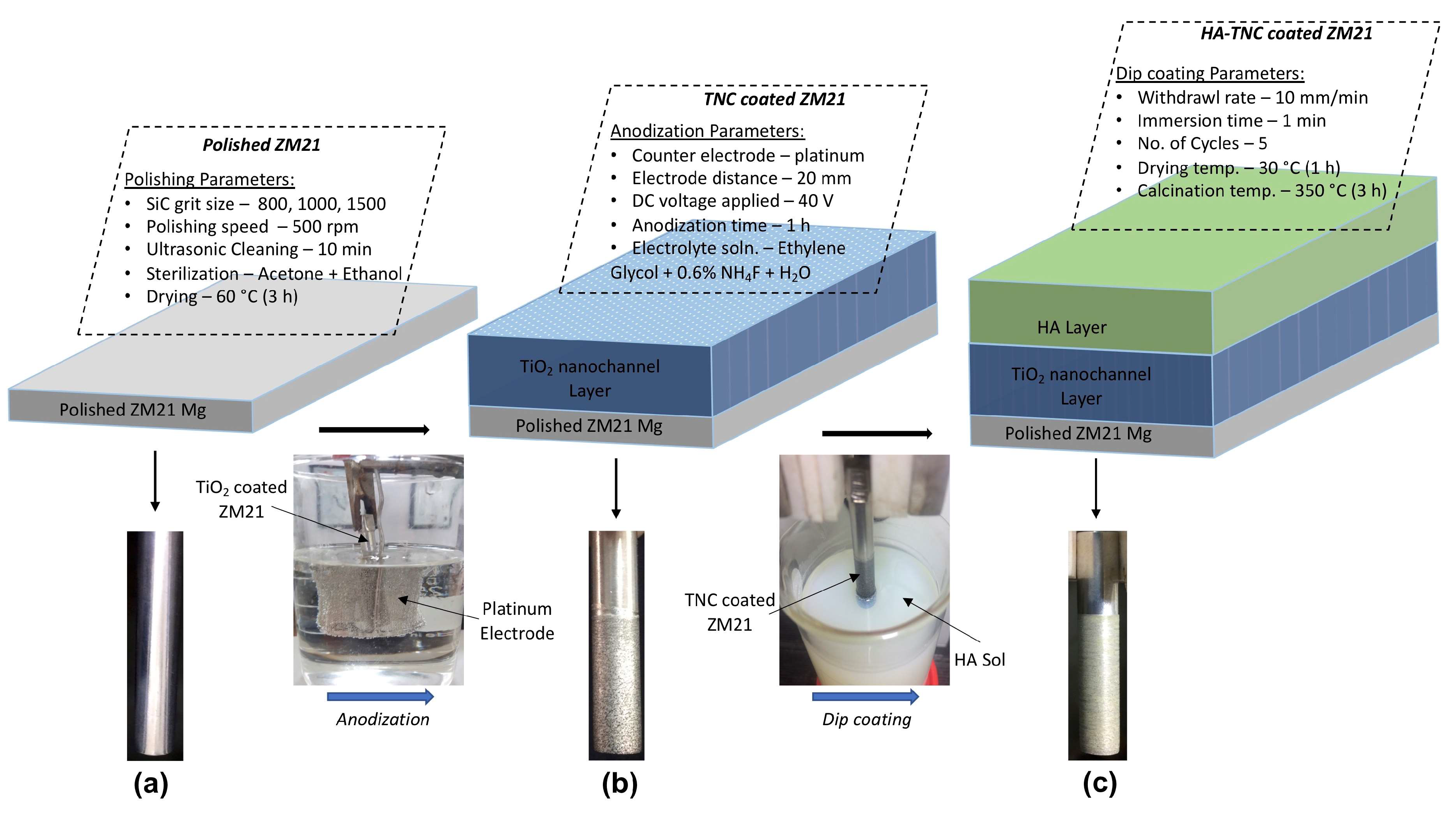
2.2. Coatings Development

2.2.1. Development of TiO2 Nano-Channeled (TNC) Coating

The TiO2 nano-channeled (TNC) coating on the ZM21 Mg alloy was achieved using the dip coating technique. To prepare the TiO2 sol, a dropwise addition of titanium (IV) n-butoxide (TiO2, Alfa-Aesar, Tewksbury, MA, USA) to ethanol (EthOH) was followed by the addition of acetic acid (HAc), the molar ratios of which were 9:1:0.1. The mixture was stirred continuously for 1 h at 45 °C at 600 rpm [15]. Being a chelating agent, acetic acid limits the hydrolysis of titanium alkoxide [16]. The cylindrical polished ZM21 Mg substrate was dipped in TiO2 sol with a dipping rate of 10 mm/min, soaked for 1 min, and withdrawn at a lift speed of 5 mm/min. Afterward, the sample was dried at 60 °C for 1 h. This cycle was repeated five times. TiO2 nano-channels were fabricated by anodizing the as−deposited TiO2 coating. An ethylene glycol solution containing 0.6 wt % NH4F and 1.0 vol% H2O served as the electrolyte. TiO2-coated samples and platinum were used as working electrodes and counter electrodes, respectively, in a conventional two-electrode anodization configuration. During the anodizing process, the electrodes were spaced 20 mm apart, and a constant DC voltage of 40 V was applied for 1 h. Immediately following anodization, the samples were washed with DI water, followed by oven-treatment at 45 °C for 1 h to ensure the complete removal of the electrolyte and moisture. As a final step, the nano-channel TiO2-coated ZM21 samples were sintered at 450 °C for 3 h at a heating rate of 5K/min, then cooled at 1 K/min to obtain the anatase crystalline phase [17].

2.2.2. Fabrication of Hydroxyapatite—TiO2 Nano-Channeled (HA−TNC) Coating

Hydroxyapatite nanopowder was synthesized via the sol-gel route to prepare HA sol. The dropwise addition of 1 M of calcium nitrate tetrahydrate (CNT, Sigma-Aldrich, Burlington, MA, USA) to 0.6 M aqueous ammonium di-hydrogen orthophosphate (DAP, Fisher Scientific, Waltham, MA, USA) at 70 °C was performed under continuous stirring of 1800 rpm for 3 h. In order to maintain a pH of 10 ± 0.1, ammonia was continuously added and monitored. The addition of ammonia also inhibited carbonate formation [18]. After stirring for 3 h, the solution was aged for 24 h. The ammonia that floated on the surface of the sol was carefully removed. The sol was then centrifuged at 3500 rpm for 2 min in a hot-water wash. The powder was then dried in a vacuum oven (MSW-218, Macro Scientific Ltd., Delhi, India) at 80 °C for 24 h. In the synthesized HA, the Ca/P molar ratio was 1.67. The obtained HA nanopowder was then mixed with ethanol to obtain 10% w/v HA sol. The TNC-coated ZM21 was dipped in HA sol with a dipping rate of 10 mm/min, soaked for 1 min, and withdrawn at a lift speed of 5 mm/min. Afterward, it was dried at 30 °C for 1 h. This step was repeated five times. After completion of the required dipping cycles, calcination at 350 °C for 3 h was performed at a heating rate of 5 K/min followed by a cooling rate of 1 K/min to achieve HA-TNC-coated ZM21.

2.3. Analysis of the Surface Morphology

A scanning electron microscope (SEM) (JEOL, Tokyo, Japan) was used to characterize the surface morphology of the samples. The samples were sputter-coated with gold at 40 mA for 50 s to avoid the charging effects. Electron-dispersive X-ray spectroscopy (EDX) was performed in point-analysis mode to analyze the elemental distribution at the surface of samples. The morphology and elemental distribution of apatite deposited after SBF immersion was observed using SEM and EDX analysis. The diameter of the nano-channels was obtained from SEM micrographs using ImageJ software. A minimum of 100 nano-channels were measured for diameter calculation. The functional groups present in the molecular structures of coatings were observed via Fourier transform infrared spectroscopy (FTIR), operated in transmission mode at a spectral domain of 400–4000 cm−1. For each sample, 16 scans were performed with a wavelength resolution of 2 cm−1. The phase composition of the coatings was characterized by X-ray diffraction (XRD) using Cu-Kα radiation (λ = 1.54 Å) for 2θ = 10° to 90°, with a step size of 0.02°. The functional groups and phase composition of apatite deposited during SBF immersion were observed using FTIR and XRD analysis. In order to determine the surface hydrophobicity, contact angle (CA) measurements were performed using SBF drops (10 μL each) as wetting media on a drop-shape analyzer (DSA25S, KRÚSS GmbH, Hamburg, Germany). The surface roughness of HA-TNC-coated, TNC-coated, and polished ZM21 Mg samples was measured using a portable surface roughness tester (SURFTEST SJ-310, Mitutoyo, Kawasaki, Japan). The surface finish of the samples was described using the arithmetic average roughness (Ra).

2.4. Electrochemical Corrosion Measurements

The electrochemical corrosion measurements were conducted on an electrochemical workstation (PGSTAT 302N, Autolab, Utrecht, The Netherlands) with a standard three-electrode cell configuration. An Ag/AgCl (1 M/L) served as the reference electrode, with a graphite rod as a counter electrode. A stable open circuit potential (OCP) was established within 1800 s before each electrochemical impedance spectroscopy (EIS) and potentiodynamic polarization (PDP) measurement. The samples were soaked in SBF (pH 7.4) with a circular exposed area (1 cm2) and acted as a working electrode. EIS was performed at OCP with a disturbing potential of 10 mV in the frequency range of 100 KHz to 0.01 Hz. The Nyquist plots were best fitted to their equivalent circuit (ECs) models using ZsimpWin 3.2 software (EChem Software, USA). PDP studies were performed at ±1 V against OCP, with a scanning rate of 1 mV s−1. The Tafel extrapolation method was used to fit the polarization curves for corrosion potential (Ecorr), current density (Icorr), polarization resistance (Rp), and corrosion rate (mm/year) measurements.

2.5. In Vitro Degradation Behavior

A simulated body fluid (SBF) (NaCl 7.99 g/L, K2HPO4.3H2O 0.22 g/L, KCl 0.22 g/L, Na2SO4 0.07 g/L, MgCl2.6H2O 0.30 g/L, CaCl2 0.27 g/L, NaHCO3 0.35 g/L, (CH2OH)3CNH2 (6.05 g/L, pH = 7.4) was used as immersion media according to the ASTM G31-72 standard. The triplicate samples at a volume-to-area ratio of 0.20 mL/mm2 were soaked in SBF at 37 °C for 7, 14, 21, and 28 days. After every 72 h, the SBF was changed, and pH was measured using a pH meter. After being removed from the SBF at pre-determined intervals, the samples were cleaned with chromic acid, rinsed in DI water, and dried under a vacuum. Using a micro-weighing machine, weight loss was calculated to determine the corresponding degradation rate, in W (mg/cm2/day). In the course of immersion, hydrogen released from the surface of the samples and the changes in pH of the media were monitored at intervals of 7 days, for up to 28 days.

3. Results and Discussion

3.1. Analysis of Surface Morphology

Figure 2a represents the SEM-EDX analysis of polished ZM21 Mg alloy. The EDX spectra show the presence of Zn, Mn, and O elements in the Mg matrix. Figure 2b shows the SEM-EDX analysis of the TNC coating deposited on polished ZM21 Mg. On the coated surface, tubular nano-channels of different sizes, ranging in diameter from 40 nm to 70 nm, have been evenly distributed. The EDX analysis performed on the TNC reveals the presence of Ti and O elements. Furthermore, the presence of Mg indicates that the tubular channels are hollow and extend up to the ZM21 Mg surface. Figure 2c shows that in the HA-TNC coating, the nano-channel openings in the TNC coating were entirely covered by the HA layer. Because of the evaporation of organic residues from the coating matrix during calcination, fewer microcracks were observed in the coating.
The SEM-EDX micrograph in Figure 2d shows the cross-sectional analysis of the coating. The HA layer and TNC layer of the HA-TNC coating have a thickness of 8.11 and 10.32 μm, respectively. The EDX analysis of the coating cross-section reveals the uniform distribution of Ca, P, and Ti in the HA layer and the TNC layer of HA-TNC coating, respectively.
Based on the EDX spectrum of HA−TNC coating, the Ca/P ratio that has been calculated is 1.26, which is significantly less than the stochiometric Ca/P ratio (1.67) of HA, indicating that HA is deficient in calcium. It is likely that Mg2+ leached out of the Mg alloy substrate and replaced the Ca sites present in the apatite. Figure 2d shows a cross-sectional view of the HA−TNC coating, indicating densely packed, randomly oriented tubular nano-channels beneath the HA layer.
In Figure 3a, the FTIR spectrum of the TNC coating displays the characteristic bands at wavenumbers 618 and 661 cm−1, associated with Ti-O-Ti and O-Ti-O vibrations in the crystal structures. The peak observed at 1352 cm−1 signifies the presence of Ti-O bonds [19]. The doublet at 1445 and 1539 cm−1 is related to the symmetric and asymmetric stretching of the carboxylic group, coordinated to Ti [20]. The bending vibrations of H2O and Ti-OH were observed at 1632 cm−1 [21]. The peak at 3416 cm−1 is associated with the stretching vibrations of the O-H group [22]. The spectra of HA displayed characteristic peaks at 564 cm−1, and 615 cm−14 PO43−), 1034 cm −1 and 1095 cm−13 PO43−), and 1385 cm−13 CO32−) [23]. There are characteristic peaks of TNC and HA only in the HA−TNC coatings, suggesting HA and TNC remain chemically inert. The XRD analysis of the TNC coating depicted in Figure 3b shows TiO2 peaks at 2θ of 25.17°, 37.20°, 46.69°, 54.64°, 55.78°, and 61.45° related to the (011), (004), (020), (015), (121), and (024) crystal planes. The MgO detected at 2θ of 37.59° and 61.8° corresponds to the (011) and (111) crystal planes (JCPDS card No. 96-900-2350).
The presence of MgO indicates the interaction of the coating with the Mg substrate. The HA peaks appearing at 2θ of 24.35°, 32.19°, 32.95°, 47.06°, 48.54°, and 52.28° correspond to the (002), (211), (112), (132), (213), and (004) crystal planes (JCPDS card No. 96-900-2217). According to the XRD spectrum of the HA-TNC coating, there are only peaks corresponding to HA and TNC, which indicates that no secondary compound has been formed and that the two layers of the coating remain chemically inert. Elemental and structural analysis of the HA-TNC coating confirmed its interaction with the Mg substrate. Studies have indicated that these interactions occur via electrostatic attraction and van der Waal forces [24,25,26].
The wettability of SBF with the HA-TNC-coated, TNC-coated, and polished ZM21 Mg samples was evaluated using the contact angle (CA) measurement, as shown in Figure 4. The CA value of polished ZM21 was 62.0°. The TNC coating exhibited a lower CA value (55.3°) compared to the polished substrate. However, the HA-TNC coating showed the highest CA value of 82.5°. The average surface roughness, Ra, corresponding to the polished ZM21 sample was 0.265 μm. Compared to the polished samples, the TNC-coated and HA-TNC-coated samples have higher Ra values of 0.814 and 0.652 μm, respectively. In the HA-TNC-coated sample, an improvement in the surface finish could be attributed to the application of HA layers.

3.2. Electrochemical Measurements

The PDP and EIS curves of the HA-TNC-coated, TNC-coated and polished ZM21 samples are shown in Figure 5a,b, respectively. Table 1 presents the fitted results of the PDP curves. The polished sample exhibited a highly negative Ecorr value of −1.38 V, while the TNC coating positively shifted the Ecorr to −1.19 V. The HA-TNC coating showed a further positive shift in Ecorr to −0.61 V. Accordingly, the HA−TNC coating is superior to the TNC coatings for the corrosion inhibition of ZM21 Mg samples in SBF. The corrosion current density (Icorr) shown by the HA-TNC coating (5.8 × 10⁻⁶ A/cm2) is ten times lower compared with the TNC coating (4.9 × 10⁻⁵ A/cm2), and it is significantly lower when compared with the as-polished sample (3.1 × 10⁻⁴ A/cm2). The Rp for the HA-TNC-coated ZM21 sample was calculated as 5.11 × 10⁴ Ω·cm2, which is greater in magnitude by an order of 10 and 102 when compared to the TNC-coated (1.96 × 10³ Ω·cm2) and polished ZM21 (6.20 × 10² Ω·cm2) samples, respectively. The presence of the HA layer was able to limit the penetration of the SBF, providing a higher polarization resistance than the samples coated with TNC and polished with ZM21.
According to the Nyquist plots of ZM21 coated with HA-TNC and coated with TNC, high- and medium-frequency capacitive loops were observed due to the charge transfer resistance between the substrate and solution, and ion diffusion through the corrosion products, while low-frequency inductive loops were observed for polished ZM21, due to adsorption phenomena [27]. The Rct measures the diameter of a capacitive loop at high frequencies.
It is noteworthy that the Rct of the HA−TNC−coated ZM21 was 12 and 25 times greater than that of the TNC-coated and polished ZM21 Mg samples, respectively. A higher Rct value for the HA-TNC-coated ZM21 sample indicates that the corrosion product is stable and compact, inhibiting the infiltration of the corrosive medium and hindering the charge transfer reaction. Figure 6a displays the cross-sectional analysis of the coating before corrosion testing. After corrosion testing, distorted arrays of Titania nano-channels (marked by red arrows) and broken arrays (marked by yellow arrows) were observed at the HA-TNC interface, as shown in Figure 6b.

3.3. In Vitro Degradation Behavior

The degradation of Mg alloys in SBF is accompanied by hydrogen evolution and pH change, as per chemical Equations (1) and (2) [28]:
Anodic reaction: Mg → Mg2+ + 2e
Cathodic reaction: 2H2O + 2e → H2 + 2OH
To establish the degradation tendency, the H2 evolution rate (HER) and pH changes of HA-TNC-coated ZM21, TNC-coated ZM21, and polished ZM21 Mg alloy were recorded for up to 28 days of SBF immersion. The degradation rates (W) of the samples were calculated from the relative weight loss during in vitro immersion. As observed from Figure 7a, the weight loss increases gradually at a slow rate for the HA-TNC-coated samples, whereas very steep weight loss occurred for the TNC-coated and polished ZM21 samples. Following 28 days of immersion, the net weight loss of HA-TNC-coated ZM21, TNC-coated ZM21, and ZM21 Mg samples transpired in the ratio of 1:2.9:4.8, respectively.
For an immersion period of 7 to 28 days, with an interval of 7 days, the HA-TNC-coated sample exhibited the lowest degradation rates of 0.89 ± 0.16, 0.54 ± 0.21, 0.67 ± 0.15, 1.10 ± 0.22 mg/cm2/day, compared to the TNC-coated and polished samples, which had corrosion rates of 1.24 ± 0.14, 0.97 ± 0.15, 1.33 ± 0.2, and 2.40 ± 0.25 mg/cm2/day, respectively. The higher degradation rate can be attributed to spatial defects in the TNC coating. The polished ZM21 Mg samples showed a significantly higher degradation rate than the biosafety limits prescribed for human consumption [29,30].
According to Equation (2), the hydrogen evolution rate (HER) is proportional to the anodic dissolution of the Mg. Figure 7c shows that the HER for the HA-TNC-coated sample was 1.41 ± 0.29 mL/cm2/day after 7 days of immersion in SBF, which almost remained similar for up to 14 days. Thereafter, a marginal increase in HER was observed for up to 28 days of SBF immersion. This suggests that the apatite that was mineralized on the HA-TNC-coated sample provides effective shielding against the penetration of aggressive ions that execute the degradation of the Mg substrate. In contrast, the TNC-coated and polished ZM21 samples showed an abrupt rise in HER with prolonged immersion, compared to the HA-TNC-coated ZM21 sample, as depicted in Table 2. Due to continuous H2 release for up to 28 days, HER of 2.82 ± 0.32 and 3.98 ± 0.34 mL/cm2/day was observed for the TNC-coated and polished ZM21 Mg samples.
Figure 7d shows the variation of pH recorded for HA-TNC-coated, TNC-coated, and ZM21 samples during 28 days of immersion in SBF. The pH control value was maintained at 7.40 during the whole immersion period. The HA-TNC-coated sample exhibited a minor increase in pH value for the initial 72 h of immersion. After 72 h, it is probable that the apatite formation neutralizes the pH change [31]. Even after 28 days of immersion, the pH of the solution was changed to 7.89 ± 0.1. A major pH increase was observed for the TNC-coated sample during the initial days of immersion. As the corrosion product grew, the pH change was marginally retarded for up to 14 days. Afterward, an abrupt rise in pH was observed with prolonged immersion for up to 28 days. The polished ZM21 Mg samples displayed the highest pH values, reaching 9.75, indicating severe sample degradation.

3.4. In Vitro Apatite Mineralization

Figure 8a,b depicts the surface morphology and elemental composition of TNC-coated samples after 14 and 28 days of SBF immersion, respectively. After 14 days of immersion, the coated surface has wide microcracks, which act as potential sites for SBF penetration. Mineralized apatite in the nano-channels displayed a one-dimensional, loosely packed rod-like structure. The aggressive ions present in SBF easily penetrate such structures and corrode the underlying Mg substrate. Therefore, severe degradation can be observed for the TNC−coated ZM21 sample.
Ideally, hydroxyapatite with a stochiometric Ca/P ratio of 1.67 is considered the most stable Ca/P compound during apatite formation. It has a solubility index (Ksp) of 3.7 × 10−58 and is considered nearly insoluble in physiological media; it provides significant shielding against the aggressive Cl ions present in SBF [32]. The sudden increase of Mg2+ ions released from the substrate during corrosion cause significant cationic substitution in apatite. Compared to Ca2+ ions (0.099 nm), the size of Mg2+ ions is relatively smaller (0.069 nm), which permits them to substitute Ca2+ ions in the mineralized apatite [26]. Such a substitution caused lattice distortion and compromised the structural stability of HA [33]. The resulting Mg-substituted Ca-deficient apatite is highly soluble and unstable. The Ca/P ratio estimated from EDX analysis suggested the mineralization of calcium-deficient hydroxyapatite (Ca-def HA) on the surface of the TNC-coated ZM21 sample. Considering the Mg amount, these deficiencies might be caused by Mg dissolving from the substrate. The density and growth of apatite were improved with prolonged immersion for up to 28 days. Therefore, the amount of Mg leached to the surface is significantly dropped. Consequently, the Ca/P ratio was increased to 1.19, although the Ca/P ratio of apatite is lower than its stoichiometric value of 1.67, indicating poor stability of deposited apatite.
Figure 9a,b shows the surface morphology and elemental composition of HA-TNC-coated samples after 14 and 28 days of SBF immersion, respectively. After 14 days, the apatite on the sample is compact and homogeneously distributed, exhibiting a 2D plate-like morphology. Fewer micro-cracks were observed compared to the TNC-coated ZM21 sample. With increasing immersion time for up to 28 days, the apatite growth became denser, more compact, and homogeneous, as shown in Figure 9b. Such an apatite formation provided significant shielding between SBF and the coated sample.
According to the EDS analysis, the atomic percentage of Ca, P, and Mg elements in apatite deposited on HA-TNC-coated and TNC−coated ZM21 samples are compared in Figure 10. The HA-TNC-coated sample had the highest Ca and P distribution and the lowest Mg content among all the samples, showing it had allowed the least amount of Mg ions to leach. The Ca/P ratio of apatite mineralized on the TNC-coated ZM21 sample is lower than on the HA-TNC-coated ZM21 sample; therefore, it was inferred that the apatite deposited on the TNC-coated ZM21 sample did not provide significant shielding against SBF penetration. Thus, the substrate continued to leach Mg2+ ions. Consequently, the corrosion continued with prolonged immersion for up to 28 days, resulting in a high degradation rate, weight loss, hydrogen evolution rate, and abrupt pH change compared to the HA-TNC-coated sample.
Figure 11a shows the FTIR spectrum of apatite mineralized on TNC-coated and HA-TNC-coated ZM21 samples after 14 and 28 days of SBF immersion. The spectra of apatite mineralized on the HA-TNC-coated sample after 28 days display characteristic peaks at 563 and 605 cm−14 PO43−), 1035 and 1092 cm−13 PO43−), and 1385 cm−13 CO32−), which represents good mapping with the characteristic peaks of HA [34,35,36]. The peaks at 460 and 1645 cm−1 are related to Mg–O and δ(O–H), respectively. Additionally, a peak at 1418 cm−1 is associated with the adsorption of carbonate (i.e., CO32−) on mineralized apatite [37], as the deposited apatite impedes the release of Mg2+ from the scratched region. Consequently, the Mg-O peaks diminished with prolonged immersion. The intensity of the PO43− peaks increased in order; TNC-coated ZM21 (14 days) < TNC-coated ZM21 (28 days) < HA-TNC-coated ZM21 (14 days) < HA-TNC-coated ZM21(28 days) samples. A simultaneous drop in the Mg-O peaks was observed with the increasing intensity of PO43− peaks. Typically, these effects suggest that the corrosion products are mineralized from structurally disordered Ca-Def HA [38,39,40].
The XRD characterization of mineralized apatite on HA-TNC-coated ZM21 and TNC-coated ZM21 samples after 14 and 28 days of SBF immersion is shown in Figure 11b. The apatite mineralized on HA−TNC−coated ZM21 after 14 days showed various peaks of HA (JCPDS 96-230-0274), Mg3(PO4)2 (JCPDS 96-100-8831), Mg-substituted Ca-deficient HA: Ca8.15Mg0.85P6O24 (JCPDS 96-901-2138), and Ca8.67Mg0.33P6O24 (JCPDS 96-901-2137). The intensities of the peaks corresponding to Mg3(PO4)2 decreased with prolonged immersion. Consequently, the Mg substitution in HA was also reduced, which was observed after 28 days of immersion; the HA characteristic peaks at 2θ = 31.8°, 32.1°, 32.9°, 46.7°, and 49.4° were augmented, whereas the intensities of peaks related to the Mg3(PO4)2, Ca8.15Mg0.85P6O24, and Ca8.67Mg0.33P6O24 compounds were reduced and suppressed after 28 days of immersion. Alternatively, the XRD spectra of apatite mineralized on TNC-coated ZM21 show various peaks of Mg3(PO4)2 and Mg-substituted Ca-deficient HA compounds, which dominated the spectra for up to 28 days of immersion in SBF.
The mineralized HA must have its c-axis [001] parallel to the longitudinal fibrils of cortical bone to deeply penetrate inside the collagen fibrils of natural bone for better adhesion [41,42]. Because HA crystals grow along their c-axis, they have an enhanced osteoinductive ability to induce osteogenic differentiation and osteoblasts and to stimulate the formation of regenerating bone, an essential characteristic for regenerating large bone defects [43]. The XRD patterns depicted in Figure 11b confirmed mineralized apatite crystals’ [002] planar orientation. The resulting HA shape ensures that mineralized apatite aligns with collagen fibrils of cortical bone, thereby resembling the fundamental structure of human bone.

4. Conclusions

The present study investigated the electrochemical corrosion and in vitro degradation behavior of HA-TNC-coated ZM21 and compared it with TNC-coated ZM21 and polished ZM21 Mg-alloy. The HA−TNC coating has shown significant protection for ZM21 Mg alloy. The results of this study are summarized as follows:
  • HA-TNC coatings with a HA layer at the top and TiO2 nano-channeled layer at the bottom were successfully developed on ZM21 Mg alloy by combining sol-gel dip coating and anodizing techniques.
  • The polarization resistance (Rp) of 5.11 × 10⁴ Ω·cm2 provided by the HA-TNC coatings was 26 and 82 times better than TNC-coated ZM21 and ZM21 Mg alloy, respectively. Therefore, the corrosion rate produced was 8.5 and 53.6 times lower compared to TNC-coated ZM21 and ZM21 Mg alloy.
  • During in vitro immersion for up to 28 days in SBF, the HA-TNC coating maintained the lowest recorded degradation rate and hydrogen evolution rate (HER) of 1.10 ± 0.22 mg/cm2/day and 1.83 ± 0.41 mL/cm2/day, respectively. In contrast, the TNC coating and the polished ZM21 Mg failed to maintain such good corrosion resistance.
  • A compact and structurally stable 2D plate-like HA (Ca/P:1.55), mineralized on HA-TNC-coated ZM21 samples, provided effective shielding against the penetration of aggressive ions with prolonged SBF immersion. Comparatively, the shielding ability of apatite mineralized on TNC-coated ZM21 samples was compromised by poor Ca/P ratios, due to excessive Mg substitution caused by Mg2+ ions leached from the ZM21 substrate.

Author Contributions

Writing-original draft preparation: N.S., Conceptualization and formal analysis: U.B., Writing-review and editing: K.K. and A.N.S. All authors have read and agreed to the published version of the manuscript.

Funding

This research received no external funding.

Institutional Review Board Statement

Not applicable.

Informed Consent Statement

Not applicable.

Data Availability Statement

Not applicable.

Conflicts of Interest

The authors declare no conflict of interest.

References

  1. Sánchez-Fernández, M.J.; Hammoudeh, H.; Félix Lanao, R.P.; van Erk, M.; van Hest, J.C.M.; Leeuwenburgh, S.C.G. Bone-Adhesive Materials: Clinical Requirements, Mechanisms of Action, and Future Perspective. Adv. Mater. Interfaces 2019, 6, 1802021. [Google Scholar] [CrossRef]
  2. Borgström, F.; Karlsson, L.; Ortsäter, G.; Norton, N.; Halbout, P.; Cooper, C.; Lorentzon, M.; McCloskey, E.V.; Harvey, N.C.; Javaid, M.K.; et al. Fragility Fractures in Europe: Burden, Management and Opportunities. Arch. Osteoporos. 2020, 15, 59. [Google Scholar] [CrossRef] [PubMed] [Green Version]
  3. Tsakiris, V.; Tardei, C.; Clicinschi, F.M. Biodegradable Mg Alloys for Orthopedic Implants—A Review. J. Magnes. Alloys 2021, 9, 1884–1905. [Google Scholar] [CrossRef]
  4. Singh, N.; Batra, U.; Kumar, K.; Ahuja, N.; Mahapatro, A. Progress in Bioactive Surface Coatings on Biodegradable Mg Alloys: A Critical Review towards Clinical Translation. Bioact. Mater. 2023, 19, 717–757. [Google Scholar] [CrossRef]
  5. Amukarimi, S.; Mozafari, M. Biodegradable Magnesium-based Biomaterials: An Overview of Challenges and Opportunities. MedComm 2021, 2, 123–144. [Google Scholar] [CrossRef]
  6. Gonzalez, J.; Hou, R.Q.; Nidadavolu, E.P.S.; Willumeit-Römer, R.; Feyerabend, F. Magnesium Degradation under Physiological Conditions—Best Practice. Bioact. Mater. 2018, 3, 174–185. [Google Scholar] [CrossRef]
  7. Sekar, P.; Narendranath, S.; Desai, V. Recent Progress in in Vivo Studies and Clinical Applications of Magnesium Based Biodegradable Implants—A Review. J. Magnes. Alloys 2021, 9, 1147–1163. [Google Scholar] [CrossRef]
  8. Li, L.-Y.; Cui, L.-Y.; Zeng, R.-C.; Li, S.-Q.; Chen, X.-B.; Zheng, Y.; Kannan, M.B. Advances in Functionalized Polymer Coatings on Biodegradable Magnesium Alloys—A Review. Acta Biomater. 2018, 79, 23–36. [Google Scholar] [CrossRef]
  9. Singh, N.; Batra, U.; Kumar, K.; Mahapatro, A. Investigating TiO2–HA–PCL Hybrid Coating as an Efficient Corrosion Resistant Barrier of ZM21 Mg Alloy. J. Magnes. Alloys 2021, 9, 627–646. [Google Scholar] [CrossRef]
  10. Ali, M.; Elsherif, M.; Salih, A.E.; Ul-Hamid, A.; Hussein, M.A.; Park, S.; Yetisen, A.K.; Butt, H. Surface Modification and Cytotoxicity of Mg-Based Bio-Alloys: An Overview of Recent Advances. J. Alloys Compd. 2020, 825, 154140. [Google Scholar] [CrossRef]
  11. Ion, R.; Mazare, A.; Dumitriu, C.; Pirvu, C.; Schmuki, P.; Cimpean, A. Nanochannelar Topography Positively Modulates Osteoblast Differentiation and Inhibits Osteoclastogenesis. Coatings 2018, 8, 294. [Google Scholar] [CrossRef] [Green Version]
  12. Gunputh, U.F.; Le, H. A Review of In-Situ Grown Nanocomposite Coatings for Titanium Alloy Implants. J. Compos. Sci. 2020, 4, 41. [Google Scholar] [CrossRef] [Green Version]
  13. Wang, X.; Li, Z.; Shi, J.; Yu, Y. One-Dimensional Titanium Dioxide Nanomaterials: Nanowires, Nanorods, and Nanobelts. Chem. Rev. 2014, 114, 9346–9384. [Google Scholar] [CrossRef] [PubMed]
  14. Rahman, M.; Dutta, N.K.; Roy Choudhury, N. Magnesium Alloys With Tunable Interfaces as Bone Implant Materials. Front. Bioeng. Biotechnol. 2020, 8, 564. [Google Scholar] [CrossRef] [PubMed]
  15. Singh, N.; Batra, U.; Kumar, K.; Mahapatro, A. Evaluation of Corrosion Resistance, Mechanical Integrity Loss and Biocompatibility of PCL/HA/TiO2 Hybrid Coated Biodegradable ZM21 Mg Alloy. J. Magnes. Alloys 2021, 10, 3179–3204. [Google Scholar] [CrossRef]
  16. Mori, S.; Lamastra, F.R.; Kaciulis, S.; Soltani, P.; Montesperelli, G. Low-Temperature Titania Coatings for Aluminium Corrosion Protection. Corros. Eng. Sci. Technol. 2018, 53, 44–53. [Google Scholar] [CrossRef]
  17. Tamjid, E.; Bagheri, R.; Vossoughi, M.; Simchi, A. Effect of TiO2 Morphology on in Vitro Bioactivity of Polycaprolactone/TiO2 Nanocomposites. Mater. Lett. 2011, 65, 2530–2533. [Google Scholar] [CrossRef]
  18. Sari, M.; Hening, P.; Chotimah; Ana, I.D.; Yusuf, Y. Porous Structure of Bioceramics Carbonated Hydroxyapatite-Based Honeycomb Scaffold for Bone Tissue Engineering. Mater. Today Commun. 2021, 26, 102135. [Google Scholar] [CrossRef]
  19. Azari, R.; Rezaie, H.R.; Khavandi, A. Investigation of Functionally Graded HA-TiO2 Coating on Ti–6Al–4V Substrate Fabricated by Sol-Gel Method; Techna Group S.r.l.: Forlì, Italy, 2019; Volume 45, ISBN 9821772404. [Google Scholar]
  20. Catauro, M.; Bollino, F.; Giovanardi, R.; Veronesi, P. Modification of Ti6Al4V Implant Surfaces by Biocompatible TiO2/PCL Hybrid Layers Prepared via Sol-Gel Dip Coating: Structural Characterization, Mechanical and Corrosion Behavior. Mater. Sci. Eng. C 2017, 74, 501–507. [Google Scholar] [CrossRef]
  21. Catauro, M.; Papale, F.; Bollino, F. Characterization and Biological Properties of TiO2/PCL Hybrid Layers Prepared via Sol-Gel Dip Coating for Surface Modification of Titanium Implants. J. Non-Cryst. Solids 2015, 415, 9–15. [Google Scholar] [CrossRef]
  22. Ji, X.J.; Gao, L.; Liu, J.C.; Wang, J.; Cheng, Q.; Li, J.P.; Li, S.Q.; Zhi, K.Q.; Zeng, R.C.; Wang, Z.L. Corrosion Resistance and Antibacterial Properties of Hydroxyapatite Coating Induced by Gentamicin-Loaded Polymeric Multilayers on Magnesium Alloys. Colloids Surf. B Biointerfaces 2019, 179, 429–436. [Google Scholar] [CrossRef] [PubMed]
  23. Bianco, A.; Cacciotti, I.; Lombardi, M.; Montanaro, L.; Gusmano, G. Thermalstability and Sintering Behaviour of Hydroxyapatite Nanopowders. J. Therm. Anal. Calorim. 2007, 88, 237–243. [Google Scholar] [CrossRef]
  24. Laurencin, D.; Almora-Barrios, N.; de Leeuw, N.H.; Gervais, C.; Bonhomme, C.; Mauri, F.; Chrzanowski, W.; Knowles, J.C.; Newport, R.J.; Wong, A.; et al. Magnesium Incorporation into Hydroxyapatite. Biomaterials 2011, 32, 1826–1837. [Google Scholar] [CrossRef] [PubMed] [Green Version]
  25. Bakhsheshi-Rad, H.R.; Hamzah, E.; Kasiri-Asgarani, M.; Jabbarzare, S.; Iqbal, N.; Abdul Kadir, M.R. Deposition of Nanostructured Fluorine-Doped Hydroxyapatite-Polycaprolactone Duplex Coating to Enhance the Mechanical Properties and Corrosion Resistance of Mg Alloy for Biomedical Applications. Mater. Sci. Eng. C 2016, 60, 526–537. [Google Scholar] [CrossRef] [PubMed]
  26. Cacciotti, I. Cationic and Anionic Substitutions in Hydroxyapatite. In Handbook of Bioceramics and Biocomposites; Springer International Publishing: Cham, Switzerland, 2016; pp. 145–211. ISBN 9783319124605. [Google Scholar]
  27. Jamesh, M.; Kumar, S.; Sankara Narayanan, T.S.N. Corrosion Behavior of Commercially Pure Mg and ZM21 Mg Alloy in Ringer’s Solution—Long Term Evaluation by EIS. Corros. Sci. 2011, 53, 645–654. [Google Scholar] [CrossRef]
  28. Kumar, K.; Gill, R.S.; Batra, U. Challenges and Opportunities for Biodegradable Magnesium Alloy Implants. Mater. Technol. 2018, 33, 153–172. [Google Scholar] [CrossRef]
  29. Munir, K.; Lin, J.; Wen, C.; Wright, P.F.A.; Li, Y. Mechanical, Corrosion, and Biocompatibility Properties of Mg-Zr-Sr-Sc Alloys for Biodegradable Implant Applications. Acta Biomater. 2020, 102, 493–507. [Google Scholar] [CrossRef]
  30. Peron, M.; Torgersen, J.; Berto, F. Mg and Its Alloys for Biomedical Applications: Exploring Corrosion and Its Interplay with Mechanical Failure. Metals 2017, 7, 252. [Google Scholar] [CrossRef] [Green Version]
  31. Guo, Y.; Jia, S.; Qiao, L.; Su, Y.; Gu, R.; Li, G.; Lian, J. Enhanced Corrosion Resistance and Biocompatibility of Polydopamine/Dicalcium Phosphate Dihydrate/Collagen Composite Coating on Magnesium Alloy for Orthopedic Applications. J. Alloys Compd. 2020, 817, 152782. [Google Scholar] [CrossRef]
  32. Sofronia, A.M.; Baies, R.; Anghel, E.M.; Marinescu, C.A.; Tanasescu, S. Thermal and Structural Characterization of Synthetic and Natural Nanocrystalline Hydroxyapatite. Mater. Sci. Eng. C 2014, 43, 153–163. [Google Scholar] [CrossRef]
  33. Cacciotti, I.; Bianco, A.; Lombardi, M.; Montanaro, L. Mg-Substituted Hydroxyapatite Nanopowders: Synthesis, Thermal Stability and Sintering Behaviour. J. Eur. Ceram. Soc. 2009, 29, 2969–2978. [Google Scholar] [CrossRef]
  34. Farzadi, A.; Bakhshi, F.; Solati-Hashjin, M.; Asadi-Eydivand, M.; Osman, N.A.A. Magnesium Incorporated Hydroxyapatite: Synthesis and Structural Properties Characterization. Ceram. Int. 2014, 40, 6021–6029. [Google Scholar] [CrossRef] [Green Version]
  35. Shaltout, A.A.; Allam, M.A.; Moharram, M.A. FTIR Spectroscopic, Thermal and XRD Characterization of Hydroxyapatite from New Natural Sources. Spectrochim. Acta Part A Mol. Biomol. Spectrosc. 2011, 83, 56–60. [Google Scholar] [CrossRef] [PubMed]
  36. Cox, S.C.; Jamshidi, P.; Grover, L.M.; Mallick, K.K. Preparation and Characterisation of Nanophase Sr, Mg, and Zn Substituted Hydroxyapatite by Aqueous Precipitation. Mater. Sci. Eng. C 2014, 35, 106–114. [Google Scholar] [CrossRef] [PubMed]
  37. Ren, F.; Ding, Y.; Leng, Y. Infrared Spectroscopic Characterization of Carbonated Apatite: A Combined Experimental and Computational Study. J. Biomed. Mater. Res.-Part A 2014, 102, 496–505. [Google Scholar] [CrossRef]
  38. Batra, U.; Kapoor, S.; Sharma, S. Influence of Magnesium Ion Substitution on Structural and Thermal Behavior of Nanodimensional Hydroxyapatite. J. Mater. Eng. Perform. 2013, 22, 1798–1806. [Google Scholar] [CrossRef]
  39. Suchanek, W.L.; Byrappa, K.; Shuk, P.; Riman, R.E.; Janas, V.F.; Tenhuisen, K.S. Preparation of Magnesium-Substituted Hydroxyapatite Powders by the Mechanochemical-Hydrothermal Method. Biomaterials 2004, 25, 4647–4657. [Google Scholar] [CrossRef]
  40. Kanasan, N.; Adzila, S.; Rahman, H.A.; Bano, N.; Panerselvan, G.; Hidayati, N.A. FTIR and XRD Evaluation of Magnesium Doped Hydroxyapatite/Sodium Alginate Powder by Precipitation Method. Key Eng. Mater. 2018, 791, 45–49. [Google Scholar] [CrossRef]
  41. Lin, K.; Chang, J.; Zhu, Y.; Wu, W.; Cheng, G.; Zeng, Y.; Ruan, M. A Facile One-Step Surfactant-Free and Low-Temperature Hydrothermal Method to Prepare Uniform 3D Structured Carbonated Apatite Flowers. Cryst. Growth Des. 2009, 9, 177–181. [Google Scholar] [CrossRef]
  42. Liu, Y.; Luo, D.; Wang, T. Hierarchical Structures of Bone and Bioinspired Bone Tissue Engineering. Small 2016, 12, 4611–4632. [Google Scholar] [CrossRef]
  43. Lin, K.; Wu, C.; Chang, J. Advances in Synthesis of Calcium Phosphate Crystals with Controlled Size and Shape. Acta Biomater. 2014, 10, 4071–4102. [Google Scholar] [CrossRef] [PubMed]
Figure 1. Synthesis route for the preparation of: (a) polished ZM21, (b) TiO2 nano-channeled (TNC)-coated ZM21, and (c) Hydroxyapatite (HA)-TNC-coated ZM21 samples.
Coatings 13 00030 g001
Figure 2. SEM-EDX analysis of: (a) polished ZM21, (b) TNC-coated ZM21, (c) HA-TNC-coated ZM21, and (d) cross-section of HA-TNC-coated ZM21.
Coatings 13 00030 g002
Figure 3. (a) FTIR spectrums and (b) XRD patterns of the TNC coating, HA coating, and HA-TNC coating.
Coatings 13 00030 g003
Figure 4. Contact angles of SBF on the surface of: (a) polished ZM21, (b) TNC-coated ZM21, and (c) HA-TNC-coated ZM21 samples.
Coatings 13 00030 g004
Figure 5. (a) PDP curves, (b) Nyquist plots of HA-TNC-coated ZM21, TNC-coated ZM21, and the polished ZM21 Mg sample.
Coatings 13 00030 g005
Figure 6. Cross-sectional analysis of the HA-TNC coating (a) before and (b) after corrosion testing.
Coatings 13 00030 g006
Figure 7. In vitro immersion study showing (a) weight loss (%), (b) in vitro degradation rate, (c) HER, and (d) pH change of immersion media, corresponding to HA-TNC-coated ZM21, TNC-coated ZM21, and polished ZM21 samples.
Coatings 13 00030 g007
Figure 8. SEM-EDX characterization of TNC-coated ZM21 after (a) 14 days and (b) 28 days of SBF immersion.
Coatings 13 00030 g008
Figure 9. SEM-EDX characterization of HA-TNC-coated ZM21 after (a) 14 days and (b) 28 days of SBF immersion.
Coatings 13 00030 g009
Figure 10. The atomic percentage of Ca, P, and Mg elements in apatite deposited on HA-TNC-coated ZM21, and TNC-coated ZM21 samples after 14 and 28 days of SBF immersion.
Coatings 13 00030 g010
Figure 11. (a) FTIR spectrums and (b) XRD patterns of apatite mineralized on HA-TNC-coated ZM21, and TNC-coated ZM21 samples after 14 and 28 days of SBF immersion.
Coatings 13 00030 g011
Table 1. The fitted parameters of PDP curves for the HA-TNC−coated ZM21, TNC-coated ZM21, and polished ZM21 Mg alloy.
SampleEcorr
(V)
Icorr
(A/cm²)
Polarization Resistance, Rp (Ω·cm2)Corrosion Rate
(mm/Year)
HA−TNC−coated ZM21−0.615.8 × 10−65.11 × 1041.32
TNC−coated ZM21−1.194.9 × 10−51.96 × 10311.19
ZM21−1.353.1 × 10−46.20 × 10270.83
Table 2. The hydrogen evolution rate (Vh), degradation rate (W), and pH change of ZM21 samples during 28 days of immersion in SBF.
DaysSampleVh
(mL/cm2/Day)
W
(mg/cm2/Day)
pH Change
7HA-TNC-coated ZM211.41 ± 0.290.89 ± 0.160.25 ± 0.1
TNC-coated ZM211.98 ± 0.241.24 ± 0.140.66 ± 0.1
ZM21 Mg2.90 ± 0.322.49 ± 0.311.28 ± 0.1
14HA-TNC-coated ZM211.39 ± 0.130.54 ± 0.210.16 ± 0.1
TNC-coated ZM211.76 ± 0.110.97 ± 0.150.45 ± 0.1
ZM21 Mg2.71 ± 0.332.34 ± 0.141.21 ± 0.2
21HA-TNC-coated ZM211.68 ± 0.340.67 ± 0.150.28 ± 0.2
TNC-coated ZM212.24 ± 0.261.33 ± 0.20.61 ± 0.1
ZM21 Mg3.12 ± 0.403.07 ± 0.351.41 ± 0.1
28HA-TNC-coated ZM211.83 ± 0.411.10 ± 0.220.49 ± 0.1
TNC-coated ZM212.82 ± 0.322.40 ± 0.251.91 ± 0.2
ZM21 Mg3.98 ± 0.343.84 ± 0.382.35 ± 0.05
Disclaimer/Publisher’s Note: The statements, opinions and data contained in all publications are solely those of the individual author(s) and contributor(s) and not of MDPI and/or the editor(s). MDPI and/or the editor(s) disclaim responsibility for any injury to people or property resulting from any ideas, methods, instructions or products referred to in the content.

