Article

Nb and Mo Influencing the High-Temperature Wear Behavior of HVOF-Sprayed High-Entropy Alloy Coatings

Institute of Materials Science and Engineering, Chemnitz University of Technology, D-09107 Chemnitz, Germany
*
Author to whom correspondence should be addressed.
Coatings 2023, 13(1), 9; https://doi.org/10.3390/coatings13010009
Submission received: 25 November 2022 / Revised: 15 December 2022 / Accepted: 19 December 2022 / Published: 21 December 2022
(This article belongs to the Special Issue High-Entropy Alloy Coatings and Surface Functionalization)

Abstract

:
To qualify high-entropy alloys (HEAs) as resource-saving and high-temperature wear-resistant coating materials, high-velocity oxygen fuel (HVOF) coatings produced from the inert gas-atomized powder of Al0.3CrFeCoNi, Al0.3CrFeCoNiNb0.5 and Al0.3CrFeCoNiMo0.75 were investigated in reciprocating wear tests at temperatures at 25, 500, 700 and 900 °C. In addition to the high-temperature wear tests, the microstructure and chemical composition of the three HEAs were analyzed using scanning electron microscopy (SEM), energy dispersive spectroscopy (EDS) and X-ray diffraction (XRD). In particular, HVOF coatings are characterized by high hardness (Vickers hardness HV0.1) and low porosity, which were also determined. After high-temperature wear tests, the wear depth was measured using laser scanning microscopy (LSM). It was found that adding Nb and Mo to Al0.3CrFeCoNi significantly reduces the wear depth with increasing temperature. The wear mechanisms change from abrasive wear and delamination (25 °C and 500 °C) to a combination of (abrasion), delamination, adhesion and oxidative wear. Thereby, oxidative wear will be the primary mechanism at 900 °C for all the HVOF coatings investigated. The most important finding is that the adhesion of the oxide layer formed is improved by adding Nb and Mo, resulting in significantly reduced wear depth at 900 °C.

1. Introduction

Due to their exceptional chemical composition and improved mechanical properties, high-entropy alloys (HEAs) exhibit great potential for various applications. HEAs consist of five or more alloying elements in equimolar or near-equimolar ratios [1]. To extend this definition to a higher number of possible alloy systems, the concentration of each element should vary between 5 at.% and 35 at.% [1]. By adding further alloying elements in small proportions, the resulting multiphase alloys—also known as compositionally complex alloys (CCAs)—can be tailored for use in harsh environments, such as in gas turbines and spacecraft [2,3,4,5,6]. Thus far, the properties of HEAs for this purpose were often investigated on bulk material. Since HEAs are expensive due to their high content of cost-intensive alloying elements, especially Co and Cr, the question arises as to how HEAs can be developed for a broad technical field. A more resource-efficient manufacturing process is using HEAs as a coating material on conventional metallic substrates. In particular, coating technologies are often used to improve the wear resistance of structural components. To achieve excellent coating properties for heavily stressed surfaces, these coatings should have high hardness, low porosity, high wear resistance, and strong bonding between substrate and coating [7]. Among common coating techniques, thermal sprayed coatings, especially high-velocity oxygen fuel (HVOF) sprayed coatings, are characterized by these coating properties [8,9]. It is also well known from our own previous studies [10,11,12,13,14,15] that HVOF is promising for applying dense and high wear-resistant HEA coatings.
To further improve the wear resistance of HVOF-HEA coatings, additional alloying elements can be added to provide high hardness or form hard secondary phases [16,17,18,19,20,21]. By adding refractory elements, such as Ti, Nb, Mo, W, or V, increased high-temperature wear resistance can be achieved and existing alloying concepts can be replaced [22,23,24]. In particular, the element Mo is also known to form hierarchical microstructures [25], improving the mechanical properties and could therefore be promising for highly wear-resistant applications. Compared to currently used high-temperature materials, such as Inconel 718, HEAs alloyed with the refractory element Nb are characterized by a less pronounced decrease in hardness at temperatures above 700 °C [22]. Moreover, HEAs produced by both melting and powder metallurgy show a reduction in wear rate with increasing temperature due to the change in wear mechanisms from mainly abrasive and adhesive wear to oxidative wear and delamination [12,22,26,27,28,29]. The increase in hardness and wear resistance could be explained by forming a thin fine-grained subsurface layer due to combined oxidation and wear stresses in conjunction with the formation of additional secondary phases during testing at high temperatures [27]. In particular, this phenomenon was observed by adding Al to CrMnFeCoNi [30]. Moreover, adding Al also increases formed oxide layers’ stability, and therefore, the oxidation resistance at elevated temperatures [31,32], reducing the wear rate. In particular, improved oxidation resistance of AlCrFeCoNi was found due to the formation of compact and thin NiO, CoO oxides and spinels in combination with an Al2O3 oxide layer on the surface [33]. In addition, the element Ti was also found to enhance the oxide layer [34]. It is also known from the literature that the refractory metals Nb and Mo are suitable for improving the (abrasive) wear resistance, as they have fine eutectic microstructures that show superior mechanical properties such as high hardness, high strength, and high ductility [18,19,22,35,36]. For instance, the fully-eutectic, laser-cladded HEA AlCoCrFeNiNb0.75 exhibits the best wear behavior compared to their hypoeutectic and hypereutectic derivatives [19].
Previous studies have shown that the combination of Al, Nb, and Mo in the following chemical composition Al0.3CrFeCoNiNb0.5 and Al0.3CrFeCoNiMo0.75 resulted in fine eutectic microstructures with excellent mechanical properties [37]. As mentioned above, eutectic microstructures are known for their excellent (high-temperature) wear resistance, which has been demonstrated for laser-cladded HEAs [19]. However, it is not known whether these findings can be transferred to HVOF-sprayed coatings. Therefore, the HEAs were deposited using HVOF spraying to evaluate their high-temperature wear resistance as a coating material. Compared to the alloys containing Nb and Mo, the HEA Al0.3CrFeCoNi [27], which is often investigated and thus well characterized, exhibits lower hardness and wear resistance and is therefore used as a reference material. In this study, the influence of Nb and Mo on the high-temperature wear behavior, especially the wear depth and the reasons for changes in the wear depth, of HVOF-sprayed coatings is studied in detail.

2. Materials and Methods

The HEAs Al0.3CrFeCoNi, Al0.3CrFeCoNiNb0.5 and Al0.3CrFeCoNiMo0.75 were produced via HVOF spraying on an austenitic stainless-steel substrate (X5CrNi18-10, Sascha Hörr Edelstahlhandel e.K., Schleiden-Dreiborn, Germany). Before thermal spraying, the surface of the substrate was corundum-blasted to enhance the adhesion between the coating and substrate. Therefore, a pressure of 2.5 bar and the medium Alodur EK F24 were taken. For the HVOF coatings, inert gas-atomized powder (NANOVAL GmbH & Co.KG, Berlin, Germany) was used as feedstock material to ensure that every particle consists of the respective alloy composition. The chemical composition of the powder was determined using an energy dispersive spectroscopy (EDS) detector (EDAX, Mahwah; NJ, USA) and an acceleration voltage of 25 kV. The results are shown in Table 1. Since the EDS results were rounded to one decimal place, there may be a deviation in the sum of all chemical elements.
In addition to the spot analysis, EDS mapping of the near-surface region of the HVOF-sprayed coatings was conducted using a NEON 40 EsB (Zeiss, Jena, Germany) and an acceleration voltage of 20 kV. Furthermore, the particle size distribution was analyzed by laser diffraction examines with a Cilas 930 device (Cilas, Orléans, France) to −50 + 21 µm (−d90 + d10) for the HEA Al0.3CrFeCoNi, −87 +16 µm (−d90 + d10) for Al0.3CrFeCoNiNb0.5 and −48 +12 µm (−d90 + d10) for Al0.3CrFeCoNiMo0.75.
The HVOF coatings were applied on the substrate using the liquid-fueled HVOF thermal spray system K2 (GTV Verschleißschutz GmbH, Luckenbach, Germany). The process parameters used are summarized in Table 2.
After thermal spraying, the microhardness HV 0.1 of the HVOF coatings was determined on metallographically prepared cross-sections using a Wilson Tukon 1102 device (Buehler, Uzwil, Switzerland, 10 measurements). In addition, the coating thickness was investigated on the cross-sections by optical microscopy (Olympus GX51, Olympus, Shinjuku, Japan). The mean value of the coating thickness was calculated from 10 measurements for each HEA. In addition, the porosity was optically measured using grayscale correlation (OLYMPUS Stream software, Shinjuku, Japan). To examine the microstructure in detail, SEM (LEO 1455VP, Zeiss, Jena, Germany) was used. The phase composition of the HVOF coatings was determined by X-ray diffraction with Co Kα radiation on a D8 diffractometer equipped with a 1D Lynxeye XE detector (Bruker AXS, Billerica, MA, USA). The diffraction angle 2θ varies between 20° and 130°. The x-ray diffraction (XRD) device worked with a point focus and a 0.5 collimator.
High-temperature wear tests were conducted with an SRV-Tribometer (Optimol Instruments Prüftechnik GmbH, Munich, Germany). The oscillating movement of the counter body (Al2O3, Ø 10 mm) on the HVOF coatings was applied under atmospheric conditions. The temperature was held constant for 5 min prior to the reciprocating wear test. The parameters for the wear investigations are shown in Table 3. These parameters were chosen to compare the results with previous investigations [12,29]. The coefficient of friction (COF) was internally determined during testing.
After the high-temperature wear tests, the wear depth was analyzed by the laser scanning microscope (LSM) Keyence VK-X200 (Keyence, Osaka, Japan). Furthermore, the wear mechanisms were determined using scanning electron microscopy (SEM) and EDS (spot analysis and mapping). Additionally, cross-sections of the wear tracks were metallographically prepared. Again, the microhardness HV 0.1 was measured after high-temperature wear tests (10 measurements per HEA).

3. Results

3.1. Characterization of the Initial Microstructure

To obtain the chemical composition of the coatings after HVOF spraying, cross-sections of the Al0.3CrFeCoNi, Al0.3CrFeCoNiNb0.5 and Al0.3CrFeCoNiMo0.75 coatings were investigated using EDS. The results are shown in Table 4.
Comparing the chemical composition listed in Table 4 with the EDS results of the powder in Table 1, it was found that the chemical composition before and after HVOF spraying differs only slightly. Therefore, it can be concluded that the HVOF parameters used are suitable for producing coatings whose chemical composition is almost the same as that of the powder feedstock. The parameters used were chosen by previous work [11,12,13,14,15,37].
After HVOF spraying, the resulting coatings of the HEAs Al0.3CrFeCoNi, Al0.3CrFeCoNiNb0.5 and Al0.3CrFeCoNiMo0.75 had a thickness of approximately 350 µm. To obtain smooth surfaces suitable for the high-temperature wear tests, the surfaces of the coatings were ground to remove the rough outer area of the HVOF coating. After grinding, cross-sections of the HVOF coatings were analyzed by SEM (see Figure 1). The coating thickness after grinding ranges from 160 µm (Al0.3CrFeCoNiNb0.5) to 320 µm (Al0.3CrFeCoNi). The minimum thickness of the coatings should be 100 µm, which ensures that the samples are suitable for the high-temperature wear tests because there is no risk of testing the substrate and not the coating. This is the most important point for this investigation. Producing similar coatings thicknesses was not considered in this study. Therefore, the variations in coating thickness between the HVOF coatings can be tolerated.
In Figure 1, all coatings show typical characteristics of an HVOF coating: Unmelted particles, melted particles (splats), oxidized particles and voids [38,39]. The porosity, determined by gray-scale correlation using optical microscopy, is less than 2.0%. In the literature, the porosity of HVOF coatings varies between 0.1% and 2.0% [40]. However, using optical microscopy, it was difficult to distinguish between voids and oxidized particles due to similar gray scales. It was also found that existing voids in the powder particles were still present after HVOF spraying, leading to an increased porosity. In summary, the porosity could not be explained by the HVOF process but by the gas atomization.
Furthermore, comparing the appearance of the HVOF-sprayed coatings in Figure 1a,b (Al0.3CrFeCoNi) with Figure 1c,d (Al0.3CrFeCoNiNb0.5) as well as Figure 1e,f (Al0.3CrFeCoNiMo0.75), it was found that Al0.3CrFeCoNi exhibits an overall darker gray-scale than the HEAs alloyed with Nb and Mo. Due to their higher atomic mass (Z), these coatings appear much brighter [41]. Additionally, it was observed that the HVOF coatings of Al0.3CrFeCoNiNb0.5 (see Figure 1d) and Al0.3CrFeCoNiMo0.75 (see Figure 1f) are characterized by a higher proportion of oxidized particles (gray lamellae in Figure 1d,f). It is well known from the literature that the elements Nb and Mo are susceptible to atmospheric oxidation [42,43]. Given this, the higher proportion of oxide lamellae in the Al0.3CrFeCoNiNb0.5 and Al0.3CrFeCoNiMo0.75 HVOF coatings can be explained.
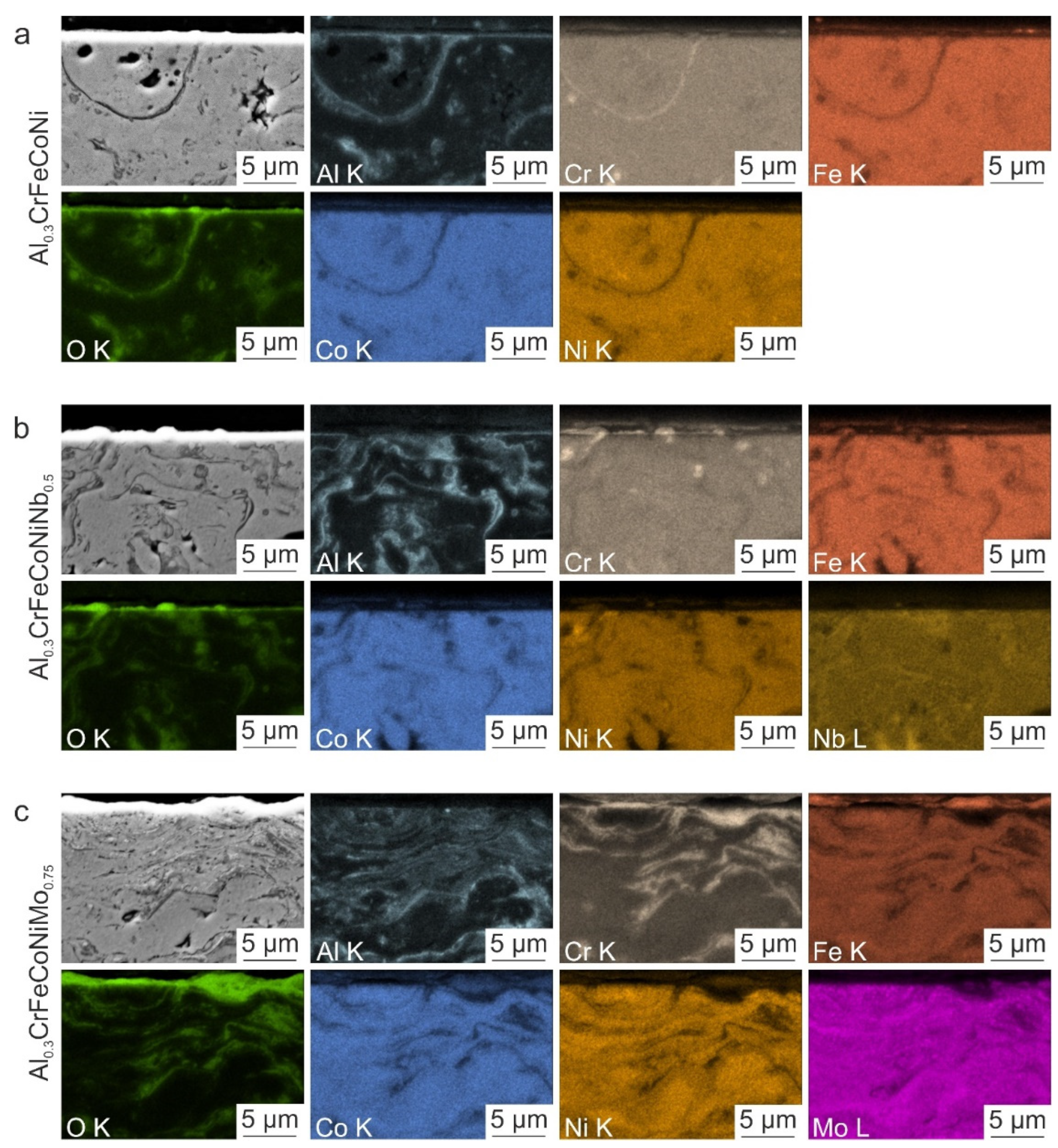
To evaluate the distribution of the alloying elements of the HVOF-sprayed coatings, EDS maps of the near-surface region were prepared. The results are given in Figure 2.
In the HVOF-sprayed Al0.3CrFeCoNi HEA coating (see Figure 2a), the elements Al, Cr, Fe, Co, and Ni are homogeneously distributed. Traces of Al, Cr, Co, and Ni were observed in the oxide lamellae. In addition, the elements Co and Ni are concentrated at the same areas in the oxide lamellae. In the HVOF-sprayed A0.3CrFeCoNiNb0.5 coating, the alloying elements are also homogeneously distributed (see Figure 2b). However, the oxide lamellae had a stronger concentration of Al than the HVOF-sprayed Al0.3CrFeCoNi coating. Furthermore, higher intensities of Ni and Nb were found in the oxide lamellae. Similar to the first HEA coatings, the HVOF-sprayed Al0.3CrFeCoNiMo0.75 (see Figure 2c) shows homogeneously distributed alloying elements with increased concentrations of Al and Cr in the oxide lamellae. In addition, the elements Co and Ni are concentrated at the same oxide lamellae. Moreover, Fe and Mo are not concentrated in the oxide lamellae. Considering the distribution of O, it was found that all HVOF-sprayed HEA coatings’ surface are enriched.
In addition to the SEM and EDS investigations, the HVOF-sprayed coatings were analyzed concerning their crystallographic and mechanical properties. In Figure 2, the results of XRD (a) and Vickers hardness (b) measurements are shown.
It was found that the HVOF coating of Al0.3CrFeCoNi consists of a single-phase face-centered cubic (FCC) lattice structure (black line, Figure 3a), which was also often found in studies of Al0.3CrFeCoNi [14,44,45]. After adding Nb (χ = 0.5), the peak of the FCC phase shifts to a smaller 2θ due to the higher atomic radius of the element Nb (compared to the other elements), which is dissolved in the solid solution and therefore leads to a higher lattice distortion than without Nb [17]. In addition, hexagonal closed-packed (HCP) phases are formed (see the dark gray line in Figure 3a). However, whether these are one or two HCP phases are not confirmed. The positions of the HCP peaks in the diffractogram are similar to those of the Laves phases commonly observed in the literature [18,19,46,47]. These Laves phases are characterized by their high hardness and brittleness. The HVOF coating of Al0.3CrFeCoNiMo0.75 also shows a shift of the FCC peaks to smaller 2θ. The atomic radius (covalent radius) of the element Mo is 154 pm [48]. This is slightly smaller than the atomic radius (covalent radius) of Nb (164 pm) [48]. The smaller angles of the FCC peaks and, thus the stronger distortion of the lattice of Al0.3CrFeCoNiMo0.75 compared to Al0.3CrFeCoNiNb0.5 can be explained by the different proportions of alloying elements. Al0.3CrFeCoNiMo0.75 contains more Mo (χ = 0.75) than Al0.3CrFeCoNiNb0.5 Nb (χ = 0.5), which leads to higher lattice distortion and shifts of the FCC peaks. In addition to the FCC phase, Al0.3CrFeCoNiMo0.75 contains a body-centered cubic (BCC) phase and a metal oxide (Me3O4). However, it was not possible to detect the type of metal oxide. Similar HVOF coatings were produced by Preuß et al. [37]. Although the same feedstock material and almost the same process parameters were used, Preuß et al. [37] observed a tetragonal phase in the HVOF-sprayed Al0.3CrFeCoNiNb0.5 and an HCP phase instead of a metal oxide in HVOF-sprayed Al0.3CrFeCoNiMo0.75 in addition to the phases in the present study. However, the peaks of the tetragonal and the HCP phases observed by Preuß et al. [37] are very small. Therefore, it is reasonable to assume that these two phases are also very small and not formed in the present study due to small deviations in the process parameters between the two studies.
Considering the results of the Vickers hardness measurement (HV 0.1) in Figure 3b, it was observed that adding Nb to Al0.3CrFeCoNi increases the microhardness to a maximum of (608 ± 77) HV 0.1 for Al0.3CrFeCoNiNb0.5. The element Mo also increases the Vickers hardness but reaches about 100 HV 0.1 less than Al0.3CrFeCoNiNb0.5. The measured hardness values are in the same range as those of HVOF-sprayed Al0.3CrFeCoNi, Al0.3CrFeCoNiNb0.5, and Al0.3CrFeCoNiMo0.75 in [37]. The increased hardness of the HVOF coatings Al0.3CrFeCoNiNb0.5 and Al0.3CrFeCoNiMo0.75 compared to Al0.3CrFeCoNi can be explained based on the additionally formed phases (see Figure 3a). Besides the single-phase FCC structure (found in all HEAs), which is known from the literature to be soft and ductile due to the high number of possible slip systems [49], the HEAs Al0.3CrFeCoNiNb0.5 and Al0.3CrFeCoNiMo0.75 consist of additional phases (HCP, BCC, and Me3O4). These are well-known for their higher hardness and brittleness (especially HCP phases) [18,19,50]. The presence of these hard phases explains the increase in Vickers hardness of Al0.3CrFeCoNiNb0.5 and Al0.3CrFeCoNiMo0.75 compared to Al0.3CrFeCoNi.

3.2. High-Temperature Wear Tests

3.2.1. Frictional Behavior

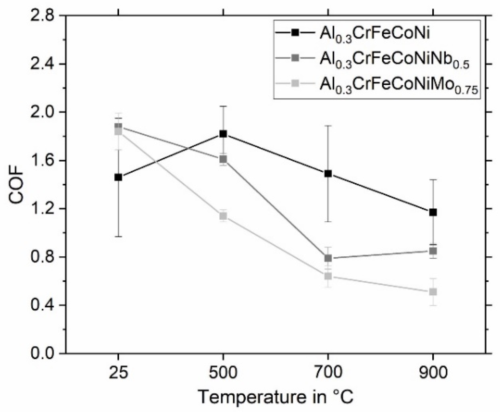
To evaluate the high-temperature wear properties of the HVOF-sprayed Al0.3CrFeCoNi, Al0.3CrFeCoNiNb0.5 and Al0.3CrFeCoNiMo0.75 coatings, reciprocating high-temperature wear tests were conducted at temperatures of 25 °C, 500 °C, 700 °C, and 900 °C, respectively. During the tests, the coefficient of friction (COF) was determined. The COF strongly fluctuated at the beginning of the test and was stabilized for the last 100 s of testing time. Therefore, the mean value and standard deviation of the last 100 s of the COF for all tests are given in Figure 4.
At a temperature of 25 °C, the HVOF-sprayed coating of Al0.3CrFeCoNi exhibits the smallest COF of approximately 1.5, compared to the HEAs Al0.3CrFeCoNiNb0.5 and Al0.3CrFeCoNiMo0.75 with COFs between 1.8 and 1.9. Similar COFs have been found in other publications dealing with HVOF–sprayed HEA coatings [12] and SPS sintered HEAs [20,29]. However, if the temperature is increased to 500 °C, the COF of Al0.3CrFeCoNi increases to 1.8, while the COFs of Al0.3CrFeCoNiNb0.5 and Al0.3CrFeCoNiMo0.75 decrease (especially Al0.3CrFeCoNiMo0.75 with a decrease of COF to 1.1). A further increase in temperature leads to a reduction in COF for all tested HVOF coatings. The HVOF coating of Al0.3CrFeCoNiNb0.5 has a minimum COF of 0.8 at 700 °C, while the other two HEAs have a minimum COF at 900 °C. At this temperature, the HVOF coating Al0.3CrFeCoNiMo0.75 exhibits the smallest COF of 0.5 in this study. It was observed that Al0.3CrFeCoNi shows the highest standard deviation at all temperatures. Therefore, it is concluded that the addition of the elements Nb and Mo reduces the COF at elevated temperatures and the standard deviations of the COFs. In the literature, the COF at 25 °C of HVOF-sprayed AlCrFeCoNiTi0.5 mentioned by Löbel et al. [12] is smaller (1.3) than in the present study (1.5). Moreover, increasing the temperature leads to decreasing the COF in the literature [12] and the present study. In particular, the HVOF-sprayed Al0.3CrFeCoNiMo0.75 coating shows a significantly lower COF of 0.5 at 900 °C compared to the HVOF-sprayed AlCrFeCoNiTi0.5 coating (1.0) [12]. This significant change in COF indicates a different wear resistance depending on the temperature load. The COF correlates strongly with the contact area between the coating and the counter body. The contact area between Al2O3 ball and HVOF coating increases with increasing wear loss. Therefore, the low COF at high temperatures indicates an in-crease in wear resistance. The wear tracks and the hardness after the high-temperature wear test were investigated, and the results are shown in the following sections.

3.2.2. Wear Depth and Vickers Hardness after High-Temperature Wear Tests

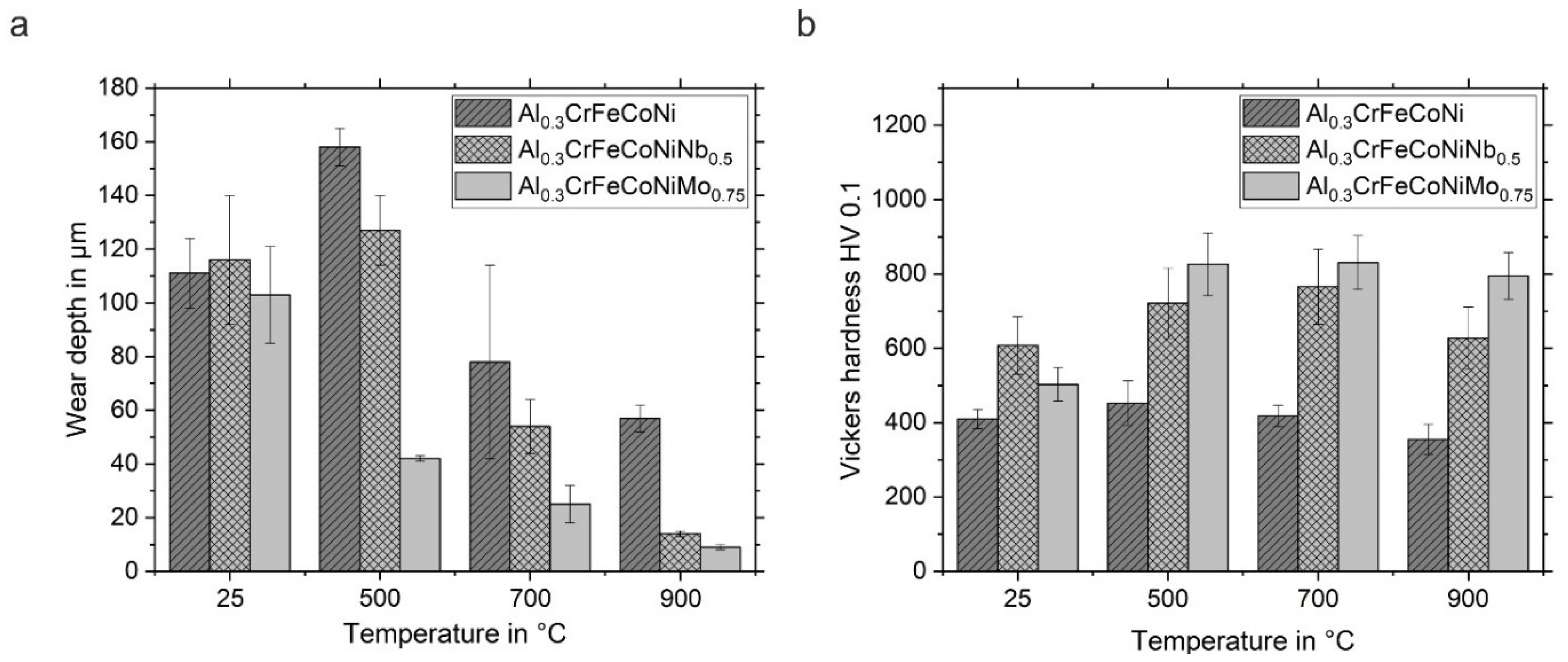
In addition to determining the COFs during high-temperature wear tests, the wear tracks were investigated using LSM. The obtained wear depths are shown in Figure 5a.
At 25 °C, the wear depths of all HVOF coatings studied are in the same range (>100 µm). The highest wear depth was observed for the HEA Al0.3CrFeCoNiNb0.5. After increasing the temperature to 500 °C, the wear depths of Al0.3CrFeCoNi and Al0.3CrFeCoNiNb0.5 increase, while the wear depth of Al0.3CrFeCoNiMo0.75 decreases significantly to approximately 40 µm. At 700 °C, a reduction in wear depths <80 µm was achieved for all HVOF coatings. Similar to the wear depths after tests at 500 °C, the HVOF-sprayed Al0.3CrFeCoNi coating exhibits the highest wear depth compared to Al0.3CrFeCoNiNb0.5 and Al0.3CrFeCoNiMo0.75 at the same temperature. A further increase in temperature to 900 °C leads to lower wear depths between 70 µm (Al0.3CrFeCoNi) and 9 µm (Al0.3CrFeCoNiMo0.75). The determined wear depths correlate with the measured COF in Figure 4. The higher the COF, the higher the wear depth [12]. Preuß et al. [37] observed lower wear depths for the same HVOF-sprayed HEAs in reciprocating wear at room temperature, although the Vickers hardness was almost the same in both studies. However, the standard deviation of the wear depths in this study at 25 °C is much higher than that reported in [37]. Compared to this study, the HVOF-sprayed AlCrFeCoNiTi0.5 coating reported by Löbel et al. [12] shows a lower wear depth at 25 °C. However, the wear depth of AlCrFeCoNiTi0.5 determined after testing at 900 °C shows almost the same value as Al0.3CrFeCoNiMo0.75 at the same temperature. To rank the wear depths of the different HVOF-sprayed coatings at higher temperatures, the following order is concluded: Al0.3CrFeCoNi> Al0.3CrFeCoNiNb0.5 > AlCrFeCoNiTi0.5 ≥ Al0.3CrFeCoNiMo0.75.
Furthermore, the Vickers hardness HV 0.1 was determined after high-temperature wear tests on cross-sections outside the wear tracks. The results are shown in Figure 5b. For the HVOF-sprayed Al0.3CrFeCoNi coating, the hardness is slightly increased after testing at 500 °C. A further increase in temperature leads to a slight reduction in hardness. However, the differences in the hardness of the HEA Al0.3CrFeCoNi are minor with increasing temperatures. In comparison, the Vickers hardness of HVOF-sprayed Al0.3CrFeCoNiNb0.5 increases by 160 HV 0.1 up to a temperature of 700 °C. After the wear test at 900 °C, the hardness decreases to values observed at 25 °C. The formation (above 500 °C) and the dissolution (above 900 °C) of hard secondary phases may lead increase and decrease hardness with increasing temperature. In addition, the softening at 900 °C could probably be explained by the occurrence of recrystallization processes. The HEA Al0.3CrFeCoNiMo0.75 shows an increase in hardness of 320 HV 0.1 after a wear test at 500 °C. At higher temperatures, the Vickers hardness does not change significantly. It is suggested that Al0.3CrFeCoNiMo0.75 is not susceptible to softening at temperatures up to 900 °C. The hardness of currently used high-temperature materials, such as Inconel 718 is unstable in this temperature range [22]. Therefore, especially Al0.3CrFeCoNiMo0.75 is more suitable than Inconel 718 for high-temperature applications. However, it should be noted that no significant influence was observed between the Vickers hardness and the wear depth. For this reason, the decrease in wear depth of the HVOF-sprayed coatings containing Nb and Mo is not attributed to the change in Vickers hardness and the assumption that new secondary phases have formed. In summary, the low wear depth of HVOF-sprayed Al0.3CrFeCoNiNb0.5 and Al0.3CrFeCoNiMo0.75 is caused by other mechanisms than an increase in Vickers hardness after high-temperature wear tests, so further investigations (XRD, SEM, EDS) were conducted.

3.2.3. XRD Investigations after High-Temperature Wear Tests

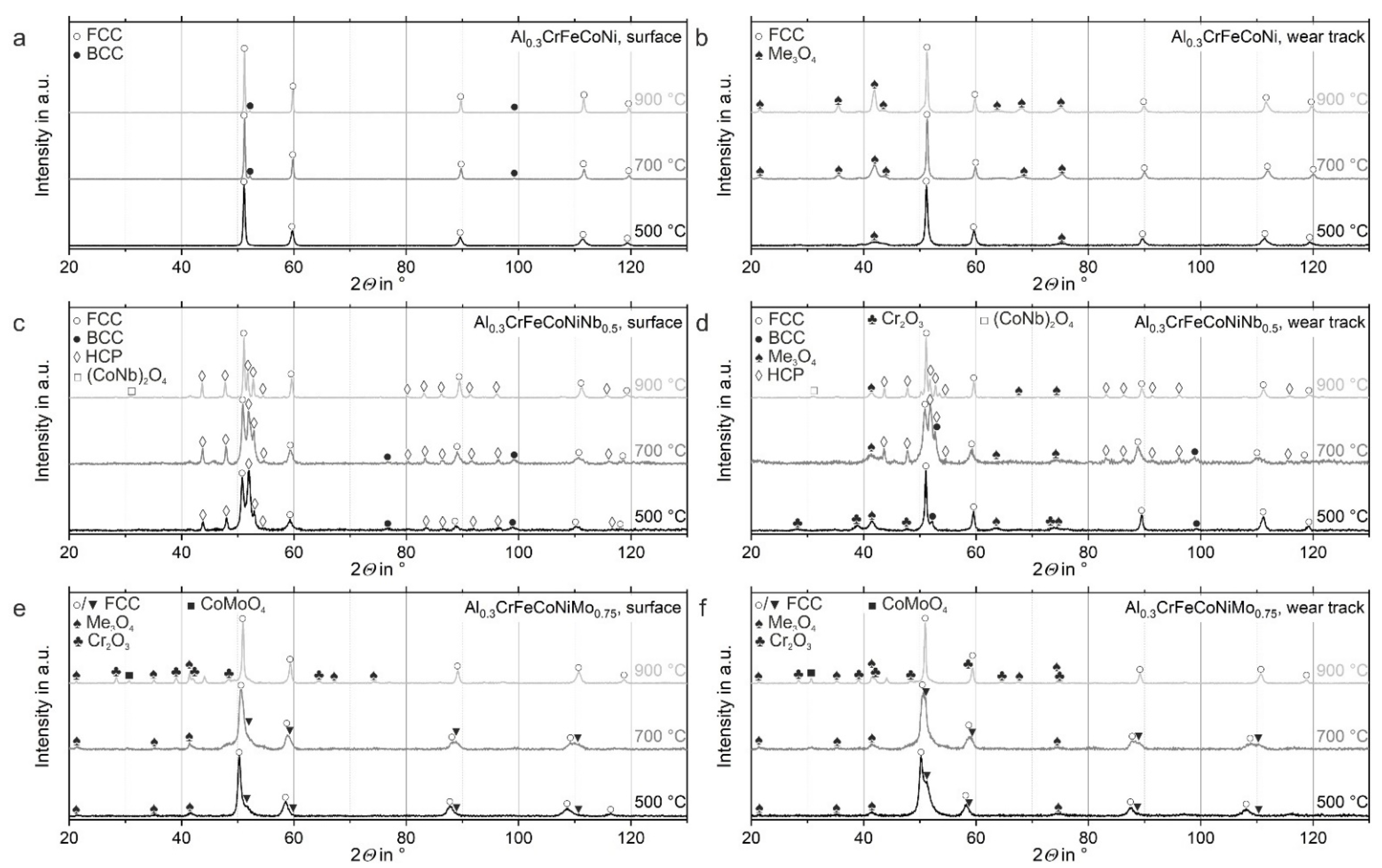
In addition, XRD measurements were performed on the surface of the samples and in the wear tracks after high-temperature wear tests. The results are shown in Figure 6. Not all peaks could be identified as sometimes only one peak was available to determine the corresponding phase, which is insufficient for a clear identification.
The HVOF-sprayed coating of Al0.3CrFeCoNi exhibits in a similar way to the as-sprayed condition a single FCC phase on the surface after testing at 500 °C (see Figure 6a). However, at 700 °C and 900 °C, small peaks of a BCC phase appear on the surface. Comparing the XRD results with the hardness measurements given in Figure 5b, the formation of the BCC phase at 700 °C and 900 °C does not significantly increase in hardness. Instead, the Vickers hardness decreases slightly at temperatures above 700 °C. In addition, the peaks of the FCC phase become thinner at 700 °C and 900 °C, as shown in Figure 6a. A change in grain size and dislocation structure likely occurs [51]. If thinner peaks are observed, the grain size increases, e.g., due to recrystallization processes. Recrystallization of the microstructure will also explain the slight decrease in hardness for all HVOF coatings tested at 900 °C (see Figure 5b). In the wear tracks, an FCC phase was found at all temperatures tested, and a Me3O4 was detected instead of a BCC phase (see Figure 6b). However, it was not possible to determine which metal oxide was found clearly. With increasing temperature, the number and intensity of these peaks increase, suggesting that the oxide layer formed in the wear tracks is better bonded to the HVOF coating. This could be why the decreasing wear depth shown in Figure 5a. In addition, the peaks in the wear track were found to be broader than at the surface, indicating that the dislocation density is increased or that more subgrain boundaries have been formed in the wear track compared to the surface [51]. In the literature [27], it was also found that forming a thin fine-grained subsurface under the counter body leads to higher wear resistance. In particular, the addition of Al supports the formation of such fine grains [30]. Therefore, it is concluded that HEAs alloyed with Al are promising for use as wear-resistant material.
Moreover, the surface of the HVOF-sprayed Al0.3CrFeCoNiNb0.5 coating at 500 °C and 700 °C shows, in addition to an FCC phase, the presence of an HCP phase and small peaks of a BCC phase, which is dissolved at 900 °C. The HCP phase is commonly known in the literature as Laves phase [18,19,46,47]. Laves phases are characterized by their high hardness and brittleness. In addition, the BCC phase is known for its higher hardness and could explain the increase in hardness at 500 °C and 700 °C. Similar to the surface of HVOF-sprayed Al0.3CrFeCoNi, the FCC peaks of Al0.3CrFeCoNiNb0.5 are smaller at 900 °C than at lower temperatures. Therefore, recrystallization processes probably occur at 900 °C, which could explain the slight decrease in hardness shown in Figure 5b. XRD measurements in the wear tracks show that at 500 °C, the HCP phase has disappeared, and a Me3O4, as well as a Fe2O3 metal oxide, have formed (see Figure 6d). After testing over 700 °C, the FCC phase, the BCC phase, and the Me3O4 structure are still present, but the Fe2O3 was no longer found. Instead, an HCP phase was detected (see Figure 6d), similar to that found on the surface of this alloy. The crystal structures did not change significantly after testing at 900 °C. Only the BCC phase was dissolved. In addition, the peaks of the FCC phase detected in the wear tracks were not broader than those on the surface in Figure 6c). Therefore, it was assumed that there was no increase of the dislocation density and no formation of subgrain boundaries in the wear tracks. The increase in the hardness of the HVOF-sprayed Al0.3CrFeCoNiNb0.5 coatings at 500 °C and 700 °C can be explained by the formation of the BCC phase, the Me3O4 oxide and the Fe2O3 (500 °C). At 900 °C, the hardness of the HVOF-sprayed Al0.3CrFeCoNiNb0.5 decreases (see Figure 5b), probably due to the dissolution of the BCC phase (see Figure 6d). In addition, it should be mentioned that one peak of a (NbCo)2O4 phase was found on the surface and in the wear track after testing at 900 °C (see Figure 6c,d). However, this single peak was not confirmed by a second one, so it can only be assumed that it correlates with an (NbCo)2O4 oxide.
For the HVOF-sprayed coatings of Al0.3CrFeCoNiMo0.75, the phases were the same on the surfaces and in the wear tracks. At 500 °C and 700 °C, two FCC phases with nearly similar lattice parameters were found, as the peaks are located close to each other (see Figure 5e). In addition, a Me3O4 was detected at both temperatures. After testing at 900 °C, only one FCC phase, a Me3O4 and a Cr2O3, were determined. Furthermore, the FCC peaks measured at the surface become thinner with increasing temperature. Therefore, it is assumed that recrystallization processes occur, leading to a slight reduction in hardness (see Figure 5b). In the wear tracks, no broadening of the FCC peaks was observed so the dislocation density is probably not increased. In addition, similar to the HVOF-sprayed Al0.3CrFeCoNiNb0.5 coating, a peak of a metal oxide was found, which was not confirmed by other peaks (see Figure 6e,f). After testing at 700 °C and 900 °C, a peak of a CoMoO4 oxide was found in the wear track (700 °C) and on the surface and in the wear track (900 °C). This oxide is known for its self-lubricating properties at temperatures above 500 °C [52,53] and could probably explain the lowest COF of 0.5 in this study. However, it is impossible to determine this phase reliably since the presence could not be confirmed by more than one peak in the XRD diagram.
In summary, the higher hardness and lower wear depth could be attributed to newly formed phases at higher temperatures, e.g., the BCC phase in HVOF-sprayed Al0.3CrFeCoNiNb0.5, and to the formation of metal oxides (Cr2O3 and Me3O4). The amount of metal oxides seems to be the lowest for the HVOF-sprayed Al0.3CrFeCoNi coating. This alloy also shows the highest wear depths for all temperatures tested. In comparison, Al0.3CrFeCoNiNb0.5 and Al0.3CrFeCoNiMo0.75 exhibit more (hard) secondary phases and a higher proportion of metal oxides, which could lead to lower wear depths, and thus higher wear resistance.

3.3. Microstructural Characterization of the Wear Tracks

However, the appearance of the wear tracks and the oxide layer formed is another important indicator to evaluate the high-temperature wear behavior of HVOF-sprayed HEA coatings. To examine the appearance of the wear tracks in detail, SEM investigations of the wear tracks were conducted. The resulting back-scattered electron (BSE) images are shown in Figure 7. The sliding direction of the counter body was linear oscillating. All wear tracks possess brighter and darker areas (see Figure 7b). The brighter areas are likely the HVOF coating. After testing at 25 and 500 °C, all coatings show these brighter areas characterized by grooves (see Figure 7d). In addition to these deeper grooves, the wear tracks show debris that is a product of the abrasion of the tested HVOF coating and the counter body (see Figure 7a). This darker debris are rough and lie on the surface of the wear track. The HVOF-sprayed Al0.3CrFeCoNi coating exhibits this debris at all temperatures tested, while the HEAs Al0.3CrFeCoNiNb0.5 and Al0.3CrFeCoNiMo0.75 only have debris in wear tracks tested at 25 and 500 °C. Debris is a third body between the surface and the counter body [54]. It is known from the literature [54] and confirmed by this study that the presence of debris leads to an increased COF (see Figure 4) and higher wear depths (see Figure 5a). There are also darker and smoother areas (see Figure 7b), likely due to deformation processes during testing [26]. Furthermore, small shear cracks were found at temperatures above 500 °C (see Figure 7j). Deformed surfaces and such shear cracks indicate the presence of adhesive wear [55]. In addition, delamination was found on the surfaces at all temperatures tested (see exemplarily in Figure 7b) [26].
After describing the appearance of the wear tracks, theories can be proposed about the underlying wear mechanisms. Bright metallic grooves were observed for all wear tracks tested at 25 °C and 500 °C and for the HEA coating Al0.3CrFeCoNi at all temperatures tested. These grooves usually indicate abrasive wear behavior [55]. However, for all HEAs, it can be observed that with increasing temperature, the proportion of bright metallic grooves decreases. In particular, the alloys Al0.3CrFeCoNiNb0.5 and Al0.3CrFeCoNiMo0.75 tested at 700 and 900 °C show lower proportions of bright metallic groove, so that abrasive wear is less pronounced or absent. As mentioned above, delamination of the HVOF coating was observed for all temperatures tested, indicating a proportion of delamination as an acting wear mechanism for all tested HVOF coatings and temperatures. In addition, with increasing temperature, the proportion of smoother deformed areas increases significantly and shear cracks were observed for the HVOF-sprayed coatings Al0.3CrFeCoNi and Al0.3CrFeCoNiMo0.75. These are indicators of the presence of adhesion as an acting wear mechanism. The HVOF coating of Al0.3CrFeCoNiNb0.5 also exhibits a higher number of deformed areas with increasing temperature. However, no shear cracks were found for this alloy at any of the temperatures tested. Therefore, it is concluded that adhesion is not the predominant wear mechanism. The lower adhesion tendency of Al0.3CrFeCoNiNb0.5 is probably due to the high hardness of the HVOF coating caused by the occurrence of hard HCP Laves phases. It is known from the literature [18] that hard Laves phases embedded in a softer FCC matrix significantly reduce adhesive wear. Additionally, oxidation of the worn surfaces will also influence the wear mechanism.
EDS measurements of the darker areas contain more O (about 60 at.%) than the brighter areas. The oxide layers consist of the combination of the solid solution of Al0.3CrFeCoNi, Al0.3CrFeCoNiNb0.5 and Al0.3CrFeCoNiMo0.75 and O (up to 60 at.%). The proportion of darker areas increases with increasing temperature, so oxidation and forming of an oxide layer in the wear tracks will be more pronounced at higher temperatures. In particular, the oxide layer was only found in the wear tracks, not on the surface. The increase in O content with increasing temperature suggests that the oxide layer formed becomes more homogeneous, reducing COF [27] and thus resulting in lower measured wear depths (see Figure 4 and Figure 5). Overall, oxidative wear seems to be the predominant wear mechanism for all HVOF-sprayed coatings at high temperatures.
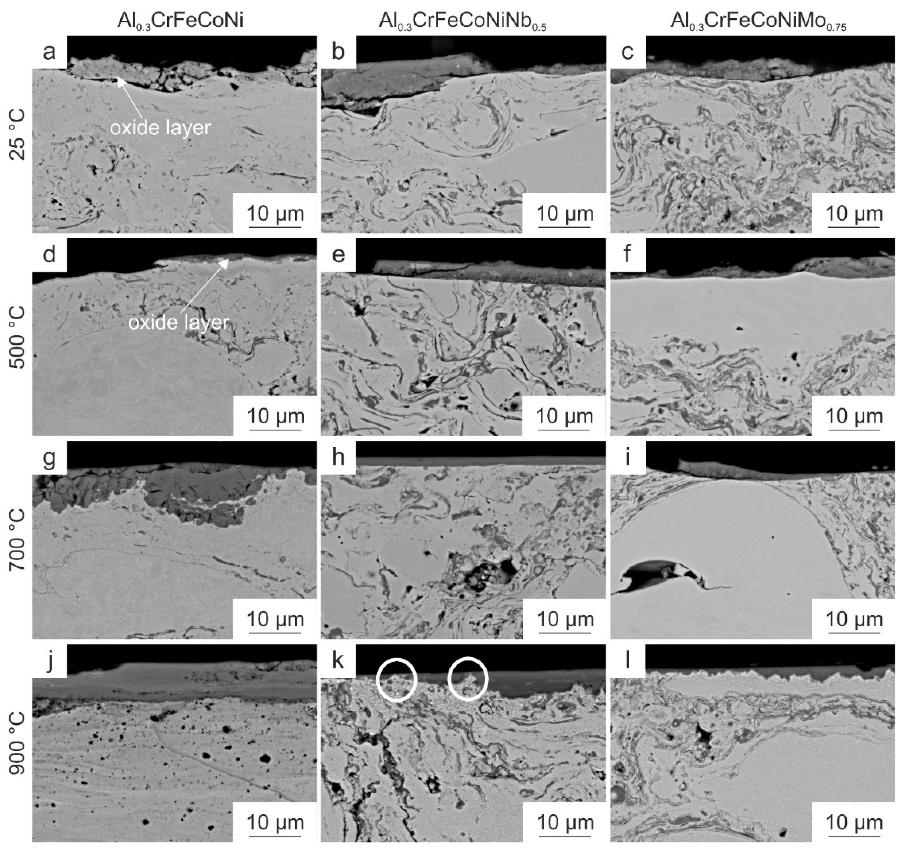
In addition, the appearance of the oxide layer formed plays an essential role in understanding the high-temperature wear behavior of the HVOF-sprayed coatings tested. To clarify this point, cross-sections of the wear tracks were analyzed using SEM. The resulting BSE images are shown in Figure 8. At 25 and 500 °C, Al0.3CrFeCoNi exhibits a thin oxide layer, as shown in Figure 8a,b. This oxide layer is characterized by cracks and a worse bonding, as spalling of the oxide layer was observed. Increasing the temperature to 700 °C leads to stronger adhesion of the oxide layer. However, the thickness of the oxide layer is not homogenous, and the oxide layer shows some cracks. Additionally, the wear track is characterized by some spalling of the oxide layer at a temperature of 900 °C, the coating thickness becomes much more homogenous, and the oxide layer appears more strongly bonded (see Figure 8j). Nevertheless, some spalling was also found.
Considering the oxide layers of Al0.3CrFeCoNiNb0.5 at 25 and 500 °C, it was found that the oxide layers are much thicker compared to those of Al0.3CrFeCoNi at the same temperatures. Nevertheless, the oxide layers are not well bonded, and spalling was found periodically across the cross-section of the wear tracks. At 700 °C, the oxide layer becomes much more homogenous (see Figure 8h). After testing at 900 °C, the oxide layer has a convoluted interface to the HVOF coating (see Figure 8k), resulting in more surface contact and, therefore, a stronger bonding between the HVOF coating and the oxide layer. In addition, the bright areas shown in Figure 7k can be attributed to the HVOF coating based on the cross-section in Figure 8k. These areas are subjected to deformation processes and are therefore embedded in the oxide layer (see white circles in Figure 8k). In addition, it was found in the literature [22] that at test temperatures of 800 °C, the oxide layer is dense and thin, leading to reduced wear depth. This was also observed for the present HVOF-sprayed Al0.3CrFeCoNiNb0.5 coating already at 700 and 900 °C and could explain the reduced wear depths at these temperatures. The oxide layer on HVOF-sprayed Al0.3CrFeCoNiMo0.75 spalled off after testing at 25, 500 and 700 °C. Furthermore, it was observed that the interface between the oxide layer and the HVOF coating becomes convoluted in some areas at 700 °C (right side in Figure 8i). However, where the interface is more linear (middle of Figure 8i), the bonding of the oxide layer is poorer, and cracks, as well as spalling, occur. A further increase in temperature to 900 °C leads to a much wavier interface between the oxide layer and the HVOF coating. In addition, a bright phase appears to form at the interface, which will have a high atom mass (Z) due to its brightness. Therefore, it is assumed that this phase could contain heavy elements such as Mo or Cr, characterized by their high hardness, thus explaining the low wear depth of HVOF-sprayed Al0.3CrFeCoNiMo0.75 at 900 °C. Figure 9 shows the interface between all HVOF-sprayed coatings and the oxide layer after testing at 900 °C. The HVOF-sprayed Al0.3CrFeCoNi coating (see Figure 9a) does not exhibit a convoluted interface compared to the Nb- and Mo-containing HVOF-sprayed coatings (see Figure 9b,c). In addition, bright and coarser phases were found in the HVOF-sprayed Al0.3CrFeCoNiNb0.5 and Al0.3CrFeCoNiMo0.75 coating close to the oxide layer. However, grain refinement in the wear track, as observed by Joseph et al. [27] and Rynio et al. [56], could not be detected.
In conclusion, the smoother and darker the wear track, the higher the temperature and O content and the more homogenous and convoluted connected the oxide layer formed, the lower the wear depth of all tested HVOF-sprayed HEAs. In addition, all HEAs show a change in wear mechanisms with increasing temperature from pronounced abrasive wear and delamination (25, 500 °C) to a combination of (abrasion), delamination, adhesive and oxidative wear. The higher the temperature, the more pronounced the oxidative wear component becomes. Similar changes of the wear mechanisms with increasing temperature were observed for the HEAs cast CrMnFeCoNi and AlχCrFeCoNi [27], laser-cladded AlCrFeCoNiNbχ [19], cast CrFeCoNiNbχ [22], HVOF-sprayed and atmospheric plasma sprayed AlCrFeCoNiTiχ [12,57]. In addition, the COF was reduced due to the change of the friction partners in the system from a metallic/oxide HVOF-sprayed coating and a ceramic counter body to a ceramic–ceramic contact between the oxide layer and the counter body. The lowest COFs were observed for the Nb- and Mo-containing HVOF-sprayed HEAs with a convoluted interface and strong adhesion of the oxide layer to the HVOF-sprayed coatings, resulting in low wear depths. In addition, the lower COF could also be attributed to the phases formed under the oxide layer (see Figure 9b,c), as they increase the resistance against the penetration of the counter body.
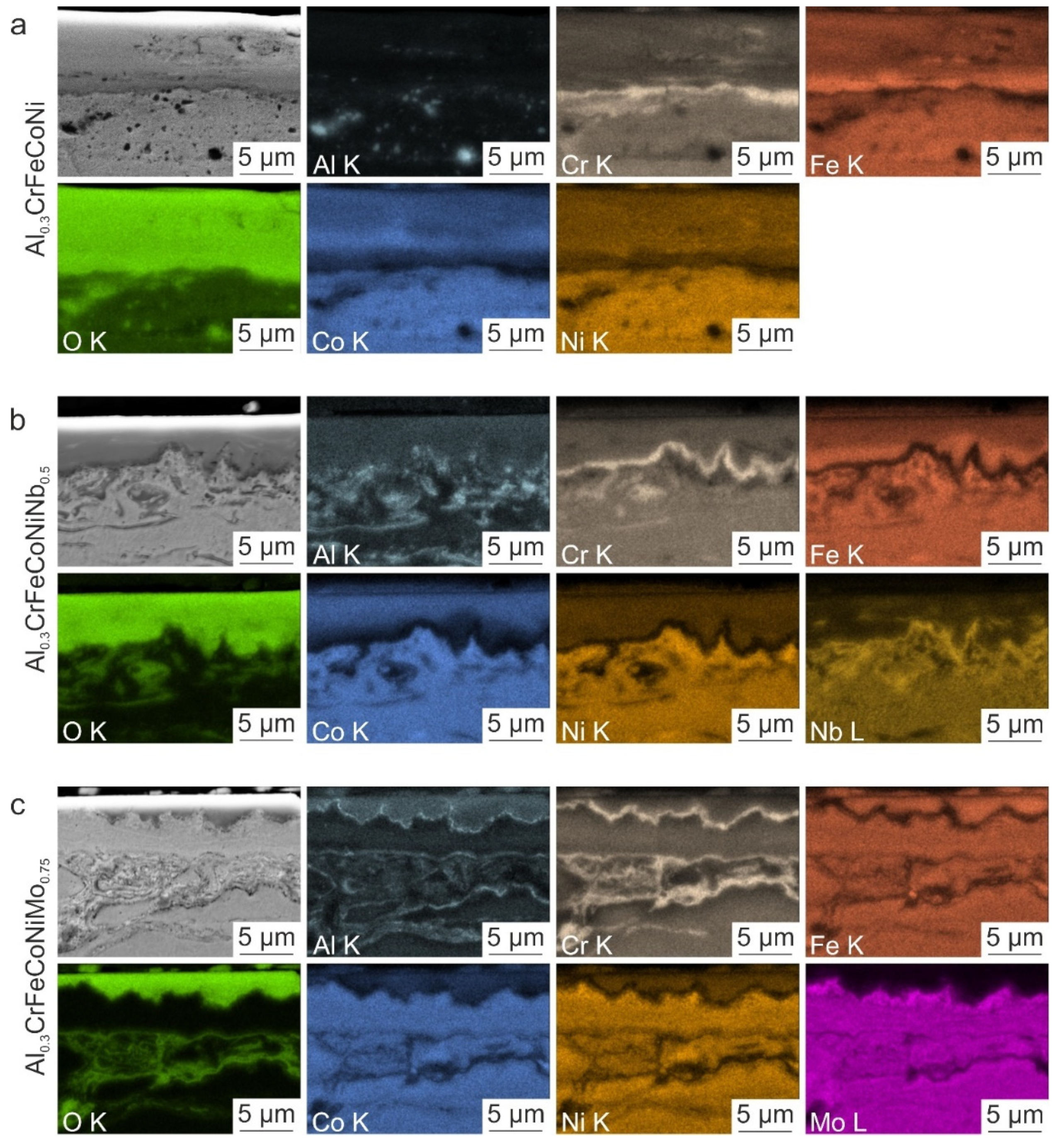
To further evaluate the influence of the alloying elements, especially Nb and Mo, EDS maps of the surface after the high-temperature wear test at 900 °C were prepared since, at this temperature, all HVOF-sprayed HEA coatings exhibited the lowest wear depth. The results are shown in Figure 10.
In HVOF-sprayed Al0.3CrFeCoNi (see Figure 10a), it was found that the elements Cr, Fe, Co, and Ni are homogeneously distributed on the surface. In addition, some pores and oxide lamellae were detected, which are particularly rich in Al and Cr. The HVOF-sprayed Al0.3CrFeCoNiNb0.5 coating exhibits a homogeneous distribution of the elements Cr, Fe, Co, Ni, and Nb (see Figure 10b). It was also found that Al is enriched in the oxide lamellae. In particular, Cr was found in the near-surface region. For the HVOF-sprayed Al0.3CrFeCoNiMo0.75 coating, it was observed that the elements Cr, Fe, Co, Ni, and Mo are homogeneously distributed and Al was concentrated in the oxide lamellae (see Figure 10c). Compared to the Nb-containing HVOF-sprayed coating, the Cr enrichment is pronounced in the oxide lamellae. At the surface, Cr, Fe and O were mainly found. This suggests that the Cr2O3 oxide found by XRD seems to be concentrated at the surface of the Mo-containing alloy after a high-temperature wear test at 900 °C. Finally, all surfaces of the HVOF-sprayed HEA coatings tested at 900 °C show an O enrichment, with the Al0.3CrFeCoNiMo0.75 alloy having the most O on the surface. This O enrichment was not found for the HVOF-sprayed coatings before testing at elevated temperatures and could, therefore, be attributed to the exposure at high temperatures.
In addition to the surface of the HVOF-sprayed coatings after testing at 900 °C, the wear tracks were also investigated concerning the distribution of the alloying elements in the oxide layer. The EDS maps obtained are shown in Figure 11. The HVOF-sprayed Al0.3CrFeCoNi coating exhibits a thick oxide layer (see Figure 11a). However, it is known from the literature [58] that thick oxide layers are prone to spall and therefore do not bond well with the material. In addition to O, the oxide layer primarily consists of Cr, Fe, Co, and Ni. The exact chemical composition of the oxide layer could not be determined using XRD. However, it is known to be a Me3O4 oxide, and from the EDS results, it can be deduced that the oxide layer consists of a (Cr, Fe, Co, Ni)3O4 oxide. It was also found that the element Cr is enriched at the interface between the HVOF-sprayed coating and the compact oxide layer. Although, XRD did not detect a Cr-oxide. Such a Cr-rich intermediate layer was also found by Joseph et al. [27] and Holcomb et al. [58]. In contrast to the literature [27,58], the Cr-rich layer was only detected in the wear track. Above this Cr-rich layer, an enrichment of Fe was found in the oxide layer. In addition, innermost Cr-rich layers were also found after magnetron-sputtering due to greater free energy reduction [59].
The oxide layer of the HVOF-sprayed coating of Al0.3CrFeCoNiNb0.5 consists of a mixture of all alloying elements (see Figure 11b). However, Nb is less pronounced in the oxide layer. The mixed oxide layer corresponds to the Me3O4 oxide detected by XRD. Similar to Al0.3CrFeCoNi, a Cr-rich region was found in the oxide layer at the interface to the HVOF-sprayed coating. However, a Cr-oxide layer could not be identified using XRD. In contrast to the HVOF-sprayed Al0.3CrFeCoNi coating, the interface between the HVOF-sprayed Al0.3CrFeCoNiNb0.5 coating and the oxide layer is convoluted. This was also observed by Hou et al. [60]. In addition to the enrichment of Cr, a higher concentration of Fe was found in the oxide layer. Moreover, Nb was enriched in the HVOF-sprayed coating directly at the interface to the oxide layer. Considering the SEM image in Figure 9b, secondary brighter phases can be observed, indicating the presence of an Nb-rich phase by combining the results of the SEM image in Figure 9 and the EDS map in Figure 11.
The oxide layer of the HVOF-sprayed coating Al0.3CrFeCoNiMo0.75 consists of Al, Cr, Fe, Co, and Ni (see Figure 11c) and is thinner than the other HVOF-sprayed coatings. Thin oxide layers are known for their stronger adhesion since thin layers are less susceptible to spalling [58]. Surprisingly, Mo was not detected in the oxide layer. Instead, Mo is concentrated at the interface between the HVOF-sprayed coating and the oxide layer. Comparing this finding with the SEM image in Figure 9c, bright phases were found at the same position, leading to the conclusion that Mo-rich phases were formed at the interface between the HVOF-sprayed coating and the oxide layer. In addition, starting from the HVOF-sprayed coating, the oxide layer shows a thin Al-rich region followed by a thicker Cr-rich region. The Al-rich oxide layer, also found by Joseph et al. [27] for Al0.3CrFeCoNi, was not detected by XRD. However, a Cr2O3 was found by XRD in the wear track of Al0.3CrFeCoNiMo0.75 after testing at 900 °C. Furthermore, Cui et al. [61] also found an innermost continuous Al-and intermediate Cr-rich-oxide layer for laser-cladded AlCrFeCoNiTi0.5 after oxidation tests at 800 °C. These layers will limit the oxygen diffusion, resulting in high oxidation resistance at elevated temperatures. In addition, thin, protective and slow-growing Al-rich oxide layers are known for their high oxidation resistance and their strong adhesion compared to other oxides [33,62]. However, it is also known that an Al-rich oxide layer forms cracks due to the difference in thermal expansion coefficient compared to the coating and is therefore prone to spalling [34]. Since this was not observed for the HVOF-sprayed coating containing Mo, it is assumed that the adhesion of the thin Al-rich oxide layer is strong and will positively affect the overall adhesion of the oxide layer to the HVOF-sprayed coating.
In summary, reactive elements such as Al can improve the adhesion of Cr-rich oxide layers [58]. However, since all alloys tested contain Al and only the HEAs with Nb and Mo form a convoluted interface, these elements will affect the formation of such an interface. In addition, a convoluted interface leads to a compact and well-bonded oxide layer, which is essential for achieving high wear resistance [22]. The lower wear depth of the Mo-containing alloy is likely due to the additional thin Al-rich oxide layer formed between the HVOF-sprayed coating and the Cr-rich oxide layer, which increases the adhesion between both compared to the HVOF-sprayed Al0.3CrFeCoNiNb0.5 coating. This study, it was found that the addition of Nb and Mo leads to good adhesion of the oxide layer to the HVOF-sprayed HEA layer due to the formation of a convoluted interface. However, it is not clarified why the elements Nb and Mo lead to the formation of such an interface. This should be part of further studies.

4. Conclusions

This study investigates the influence of Nb and Mo on the high-temperature wear resistance of HVOF-sprayed Al0.3CrFeCoNi coatings. Therefore, high-temperature wear tests were performed at temperatures of 25, 500, 700, and 900 °C on the HVOF HEA coatings Al0.3CrFeCoNi, Al0.3CrFeCoNiNb0.5 and Al0.3CrFeCoNiMo0.75. The microstructure of the HVOF-sprayed HEA coatings before and after the high-temperature wear tests was analyzed in detail, and the following findings can be drawn:
  • Adding Nb and Mo to Al0.3CrFeCoNi increases the hardness due to the hard phases formed next to the FCC phase (HCP in Al0.3CrFeCoNiNb0.5 and BCC as well as Me3O4 in Al0.3CrFeCoNiMo0.75)
  • The COF decreases with increasing temperature due to the formation of an oxide layer on the surface after high-temperature wear tests, as the friction combination changes from ceramic on metal to ceramic on ceramic
  • The wear depth decreases with increasing temperature as the wear mechanisms change from pronounced abrasion, delamination and adhesion to oxidative wear
  • The lowest wear depths were observed for the Nb- and Mo-containing HVOF-sprayed coatings due to the formation of thin and strongly adherent oxide layers
  • The strong adhesion is attributed to the formation of a convoluted interface between the oxide layer and the Nb- and Mo-containing HVOF-sprayed coating
The present study confirms that the high-temperature wear resistance of HVOF-sprayed HEAs can be significantly increased by adding Nb and Mo. Therefore, the investigated HVOF coatings Al0.3CrFeCoNiNb0.5 and Al0.3CrFeCoNiMo0.75 are promising for future use as resource-saving high-temperature wear-resistant materials. However, further studies are needed to clarify why Nb and Mo form such a convoluted and strongly adhered interface during high-temperature wear tests, resulting in the observed low wear depths. First, the adhesion of the oxide layer should be investigated for all HVOF-sprayed coatings using a scratch test. Subsequently, to understand the processes at the interface between the oxide layer and the HEA coating, TEM lamellae should be prepared and investigated in detail, particularly in regards to the interface’s chemical composition. In addition, X-ray photoelectron spectroscopy (XPS) could be used to study the chemical state of the elements in the oxide layer and determine which elements are bonded together.

Author Contributions

Conceptualization, L.-M.R. and T.L. (Thomas Linder); Data curation, L.-M.R.; Formal analysis, L.-M.R.; Funding acquisition, T.L. (Thomas Lindner) and T.L. (Thomas Lampke); Investigation, L.-M.R.; Methodology, L.-M.R. and T.L. (Thomas Lindner); Project administration, T.L. (Thomas Lindner) and T.L. (Thomas Lampke); Resources, T.L. (Thomas Lampke); Supervision, T.L. (Thomas Lampke); Validation, L.-M.R.; Writing—original draft, L.-M.R.; Writing—review & editing, T.L. (Thomas Lindner) and T.L. (Thomas Lampke). All authors have read and agreed to the published version of the manuscript.

Funding

This research was funded by the Sächsische Aufbaubank-Förderbank/SAB-100382175 by the European Social Fund ESF and the Free State of Saxony. The publication of this article was funded by Chemnitz University of Technology and by the Deutsche Forschungsgemeinschaft (DFG, German Research Foundation)—491193532.

Institutional Review Board Statement

Not applicable.

Informed Consent Statement

Not applicable.

Data Availability Statement

Not applicable.

Acknowledgments

The authors thank Robert Glaßmann for preparing the HVOF coatings, Zannatul Tazri for the support of the wear tests, metallographic preparation and hardness measurements, Paul Seidel, Christian Loos and Anton Böttcher for the metallographic preparation, as well as Marc Pügner for conducting the XRD measurements.

Conflicts of Interest

The authors declare no conflict of interest.

References

  1. Yeh, J.W.; Chen, S.K.; Lin, S.J.; Gan, J.Y.; Chin, T.S.; Shun, T.T.; Tsau, C.H.; Chang, S.Y. Nanostructured high-entropy alloys with multiple principal elements: Novel alloy design concepts and outcomes. Adv. Eng. Mater. 2004, 6, 299–303+274. [Google Scholar] [CrossRef]
  2. Zhang, Y.; Zuo, T.T.; Tang, Z.; Gao, M.C.; Dahmen, K.A.; Liaw, P.K.; Lu, Z.P. Microstructures and properties of high-entropy alloys. Prog. Mater. Sci. 2014, 61, 1–93. [Google Scholar] [CrossRef]
  3. Alaneme, K.K.; Bodunrin, M.O.; Oke, S.R. Processing, alloy composition and phase transition effect on the mechanical and corrosion properties of high entropy alloys: A review. J. Mater. Res. Technol. 2016, 5, 384–393. [Google Scholar] [CrossRef] [Green Version]
  4. Miracle, D.B.; Senkov, O.N. A critical review of high entropy alloys and related concepts. Acta Mater. 2017, 122, 448–511. [Google Scholar] [CrossRef] [Green Version]
  5. Praveen, S.; Kim, H.S. High-Entropy Alloys: Potential Candidates for High-Temperature Applications—An Overview. Adv. Eng. Mater. 2018, 20, 1700645. [Google Scholar] [CrossRef]
  6. Mishra, R.S.; Haridas, R.S.; Agrawal, P. High entropy alloys—Tunability of deformation mechanisms through integration of compositional and microstructural domains. Mater. Sci. Eng. A 2021, 812, 141085. [Google Scholar] [CrossRef]
  7. Wu, L.; Guo, X.; Zhang, J. Abrasive resistant coatings—A review. Lubricants 2014, 2, 66–89. [Google Scholar] [CrossRef] [Green Version]
  8. Thorpe, M.L.; Richter, H.J. A pragmatic analysis and comparison of HVOF processes. J. Therm. Spray Technol. 1992, 1, 161–170. [Google Scholar] [CrossRef]
  9. Li, J.; Huang, Y.; Meng, X.; Xie, Y. A Review on High Entropy Alloys Coatings: Fabrication Processes and Property Assessment. Adv. Eng. Mater. 2019, 21, 1900343. [Google Scholar] [CrossRef]
  10. Löbel, M.; Lindner, T.; Mehner, T.; Lampke, T. Microstructure and wear resistance of AlCoCrFeNiTi high-entropy alloy coatings produced by HVOF. Coatings 2017, 7, 144. [Google Scholar] [CrossRef]
  11. Löbel, M.; Lindner, T.; Hunger, R.; Berger, R.; Lampke, T. Precipitation hardening of the HVOF sprayed single-phase high-entropy alloy CrFeCoNi. Coatings 2020, 10, 701. [Google Scholar] [CrossRef]
  12. Löbel, M.; Lindner, T.; Lampke, T. High-temperature wear behaviour of AlCoCrFeNiTi0.5 coatings produced by HVOF. Surf. Coat. Technol. 2020, 403, 126379. [Google Scholar] [CrossRef]
  13. Löbel, M.; Lindner, T.; Clauß, S.; Pippig, R.; Dietrich, D.; Lampke, T. Microstructure and Wear Behavior of the High-Velocity-Oxygen-Fuel Sprayed and Spark Plasma Sintered High-Entropy Alloy AlCrFeCoNi. Adv. Eng. Mater. 2021, 23, 2001253. [Google Scholar] [CrossRef]
  14. Löbel, M.; Lindner, T.; Grimm, M.; Rymer, L.M.; Lampke, T. Influence of Aluminum and Molybdenum on the Microstructure and Corrosion Behavior of Thermally Sprayed High-Entropy Alloy Coatings. J. Therm. Spray Technol. 2021, 25, 2074–2083. [Google Scholar] [CrossRef]
  15. Löbel, M.; Lindner, T.; Mehner, T.; Rymer, L.M.; Björklund, S.; Joshi, S.; Lampke, T. Microstructure and Corrosion Properties of AlCrFeCoNi High-Entropy Alloy Coatings Prepared by HVAF and HVOF. J. Therm. Spray Technol. 2022, 31, 247–255. [Google Scholar] [CrossRef]
  16. Wu, J.M.; Lin, S.J.; Yeh, J.W.; Chen, S.K.; Huang, Y.S.; Chen, H.C. Adhesive wear behavior of AlxCoCrCuFeNi high-entropy alloys as a function of aluminum content. Wear 2006, 261, 513–519. [Google Scholar] [CrossRef] [Green Version]
  17. Huo, W.Y.; Shi, H.F.; Ren, X.; Zhang, J.Y. Microstructure and wear behavior of cocrfemnnbni high-entropy alloy coating by TIG cladding. Adv. Mater. Sci. Eng. 2015, 2015, 647351. [Google Scholar] [CrossRef] [Green Version]
  18. Jiang, H.; Jiang, L.; Qiao, D.; Lu, Y.; Wang, T.; Cao, Z.; Li, T. Effect of Niobium on Microstructure and Properties of the CoCrFeNbxNi High Entropy Alloys. J. Mater. Sci. Technol. 2017, 33, 712–717. [Google Scholar] [CrossRef]
  19. Jiang, H.; Han, K.; Li, D.; Cao, Z. Synthesis and characterization of AlCoCrFeNiNbx high-entropy alloy coatings by laser cladding. Crystals 2019, 9, 56. [Google Scholar] [CrossRef] [Green Version]
  20. Löbel, M.; Lindner, T.; Lampke, T. Enhanced wear behaviour of spark plasma sintered AlCoCrFeNiTi high-entropy alloy composites. Materials 2018, 11, 2225. [Google Scholar] [CrossRef]
  21. Löbel, M.; Lindner, T.; Mehner, T.; Lampke, T. Influence of titanium on microstructure, phase formation and wear behaviour of AlCoCrFeNiTix high-entropy alloy. Entropy 2018, 20, 505. [Google Scholar] [CrossRef] [PubMed] [Green Version]
  22. Yu, Y.; He, F.; Qiao, Z.; Wang, Z.; Liu, W.; Yang, J. Effects of temperature and microstructure on the triblogical properties of CoCrFeNiNbx eutectic high entropy alloys. J. Alloys Compd. 2019, 775, 1376–1385. [Google Scholar] [CrossRef]
  23. Zeng, X.; Liu, Z.; Wu, G.; Tong, X.; Xiong, Y.; Cheng, X.; Wang, X.; Yamaguchi, T. Microstructure and high-temperature properties of laser cladded AlCoCrFeNiTi0.5 high-entropy coating on Ti 6Al-4V alloy. Surf. Coat. Technol. 2021, 418, 127243. [Google Scholar] [CrossRef]
  24. Chen, J.; Zhou, X.; Wang, W.; Liu, B.; Lv, Y.; Yang, W.; Xu, D.; Liu, Y. A review on fundamental of high entropy alloys with promising high–temperature properties. J. Alloys Compd. 2018, 760, 15–30. [Google Scholar] [CrossRef]
  25. Saboktakin Rizi, M.; Minouei, H.; Lee, B.J.; Toroghinejad, M.R.; Hong, S.I. Effects of carbon and molybdenum on the nanostructural evolution and strength/ductility trade-off in Fe40Mn40Co10Cr10 high-entropy alloys. J. Alloys Compd. 2022, 911, 165108. [Google Scholar] [CrossRef]
  26. Du, L.M.; Lan, L.W.; Zhu, S.; Yang, H.J.; Shi, X.H.; Liaw, P.K.; Qiao, J.W. Effects of temperature on the tribological behavior of Al0.25CoCrFeNi high-entropy alloy. J. Mater. Sci. Technol. 2019, 35, 917–925. [Google Scholar] [CrossRef]
  27. Joseph, J.; Haghdadi, N.; Shamlaye, K.; Hodgson, P.; Barnett, M.; Fabijanic, D. The sliding wear behaviour of CoCrFeMnNi and AlxCoCrFeNi high entropy alloys at elevated temperatures. Wear 2019, 428–429, 32–44. [Google Scholar] [CrossRef]
  28. Joseph, J.; Haghdadi, N.; Annasamy, M.; Kada, S.; Hodgson, P.D.; Barnett, M.R.; Fabijanic, D.M. On the enhanced wear resistance of CoCrFeMnNi high entropy alloy at intermediate temperature. Scr. Mater. 2020, 186, 331–335. [Google Scholar] [CrossRef]
  29. Löbel, M.; Lindner, T.; Pippig, R.; Lampke, T. High-temperature wear behaviour of spark plasma sintered AlCoCrFeNiTi0.5 high-entropy alloy. Entropy 2019, 21, 582. [Google Scholar] [CrossRef] [Green Version]
  30. Cui, Y.; Shen, J.; Manladan, S.M.; Geng, K.; Hu, S. Wear resistance of FeCoCrNiMnAlx high-entropy alloy coatings at high temperature. Appl. Surf. Sci. 2020, 512, 145736. [Google Scholar] [CrossRef]
  31. Erdoğan, A.; Gök, M.S.; Zeytin, S. Analysis of the high-temperature dry sliding behavior of CoCrFeNiTi0.5Alx high-entropy alloys. Friction 2020, 8, 198–207. [Google Scholar] [CrossRef] [Green Version]
  32. Hong, S.; Li, J.; Zhao, P.; Xu, Y.; Li, W. Evolution in Wear and High-Temperature Oxidation Resistance of Laser-Clad AlxMoNbTa Refractory High-Entropy Alloys Coatings with Al Addition Content. Coatings 2022, 12, 121. [Google Scholar] [CrossRef]
  33. Ghadami, F.; Davoudabadi, M.A.; Ghadami, S. Cyclic Oxidation Properties of the Nanocrystalline AlCrFeCoNi High-Entropy Alloy Coatings Applied by the Atmospheric Plasma Spraying Technique. Coatings 2022, 12, 372. [Google Scholar] [CrossRef]
  34. Wu, M.; Chen, K.; Xu, Z.; Li, D.Y. Effect of Ti addition on the sliding wear behavior of AlCrFeCoNi high-entropy alloy. Wear 2020, 462, 203493. [Google Scholar] [CrossRef]
  35. Bao, Y.; Guo, L.; Zhong, C.; Song, Q.; Yang, K.; Jiang, Y.; Wang, Z. Microstructure and Wear Resistance of Fe4CoCrNiB0.2Mox (x=0, 0.5, 1) High Entropy Alloys. J. Wuhan Univ. Technol. Sci. Ed. 2022, 37, 261–269. [Google Scholar] [CrossRef]
  36. Zhu, J.M.; Fu, H.M.; Zhang, H.F.; Wang, A.M.; Li, H.; Hu, Z.Q. Microstructures and compressive properties of multicomponent AlCoCrFeNiMox alloys. Mater. Sci. Eng. A 2010, 527, 6975–6979. [Google Scholar] [CrossRef]
  37. Preuß, B.; Lindner, T.; Uhlig, T.; Wagner, G.; Lampke, L. Niobium and Molybdenum as Alloying Constituents in Al0.3CoCrFeNi to Develop Eutectic High-Entropy Alloys for HVOF Spraying. J. Therm. Spray Technol. 2022, 1–10. [Google Scholar] [CrossRef]
  38. Davis, J.R. Handbook of Thermal Spray Technology; ASM International: Almere, The Netherlands, 2004. [Google Scholar]
  39. Tejero-Martin, D.; Rezvani Rad, M.; McDonald, A.; Hussain, T. Beyond Traditional Coatings: A Review on Thermal-Sprayed Functional and Smart Coatings; Springer: Berlin/Heidelberg, Germany, 2019; Volume 28. [Google Scholar]
  40. Sidhu, T.S.; Prakash, S.; Agrawal, R.D. State of the art of HVOF coating investigations—A review. Mar. Technol. Soc. J. 2005, 39, 53–64. [Google Scholar] [CrossRef]
  41. Robinson, V.N.E. Imaging with backscattered electrons in a scanning electron microscope. Scanning 1980, 3, 15–26. [Google Scholar] [CrossRef]
  42. del Moricca, M.; Varma, S.K. High temperature oxidation characteristics of Nb-10W-XCr alloys. J. Alloys Compd. 2010, 489, 195–201. [Google Scholar] [CrossRef]
  43. Gatzen, C.; Smokovych, I.; Scheffler, M.; Krüger, M. Oxidation-Resistant Environmental Barrier Coatings for Mo-Based Alloys: A Review. Adv. Eng. Mater. 2021, 23, 2001016. [Google Scholar] [CrossRef]
  44. Shun, T.T.; Du, Y.C. Microstructure and tensile behaviors of FCC Al0.3CoCrFeNi high entropy alloy. J. Alloys Compd. 2009, 479, 157–160. [Google Scholar] [CrossRef]
  45. Wang, W.R.; Wang, W.L.; Wang, S.C.; Tsai, Y.C.; Lai, C.H.; Yeh, J.W. Effects of Al addition on the microstructure and mechanical property of AlxCoCrFeNi high-entropy alloys. Intermetallics 2012, 26, 44–51. [Google Scholar] [CrossRef]
  46. He, F.; Wang, Z.; Shang, X.; Leng, C.; Li, J.; Wang, J. Stability of lamellar structures in CoCrFeNiNbx eutectic high entropy alloys at elevated temperatures. Mater. Des. 2016, 104, 259–264. [Google Scholar] [CrossRef]
  47. Liu, W.H.; He, J.Y.; Huang, H.L.; Wang, H.; Lu, Z.P.; Liu, C.T. Effects of Nb additions on the microstructure and mechanical property of CoCrFeNi high-entropy alloys. Intermetallics 2015, 60, 1–8. [Google Scholar] [CrossRef]
  48. Cordero, B.; Gómez, V.; Platero-Prats, A.E.; Revés, M.; Echeverría, J.; Cremades, E.; Barragán, F.; Alvarez, S. Covalent radii revisited. J. Chem. Soc. Dalt. Trans. 2008, 21, 2832–2838. [Google Scholar] [CrossRef]
  49. Inal, K.; Neale, K.W.; Aboutajeddine, A. Forming limit comparisons for FCC and BCC sheets. Int. J. Plast. 2005, 21, 1255–1266. [Google Scholar] [CrossRef]
  50. Liang, H.; Yao, H.; Qiao, D.; Nie, S.; Lu, Y.; Deng, D.; Cao, Z.; Wang, T. Microstructures and Wear Resistance of AlCrFeNi2W0.2Nbx High-Entropy Alloy Coatings Prepared by Laser Cladding. J. Therm. Spray Technol. 2019, 28, 1318–1329. [Google Scholar] [CrossRef]
  51. Ungár, T. Microstructural parameters from X-ray diffraction peak broadening. Scr. Mater. 2004, 51, 777–781. [Google Scholar] [CrossRef]
  52. Yang, J.F.; Jiang, Y.; Hardell, J.; Prakash, B.; Fang, Q.F. Influence of service temperature on tribological characteristics of self-lubricant coatings: A review. Front. Mater. Sci. 2013, 7, 28–39. [Google Scholar] [CrossRef]
  53. Motallebzadeh, A.; Atar, E.; Cimenoglu, H. Sliding wear characteristics of molybdenum containing Stellite 12 coating at elevated temperatures. Tribol. Int. 2015, 91, 40–47. [Google Scholar] [CrossRef]
  54. Patel, P.; Alidokht, S.A.; Sharifi, N.; Roy, A.; Harrington, K.; Stoyanov, P.; Chromik, R.R.; Moreau, C. Microstructural and Tribological Behavior of Thermal Spray CrMnFeCoNi High Entropy Alloy Coatings. J. Therm. Spray Technol. 2022, 31, 1285–1301. [Google Scholar] [CrossRef]
  55. Sommer, K.; Heinz, R.; Schöfer, J. Verschleiß Metallischer Werkstoffe; Springer Vieweg: Wiesbaden, Germany, 2018. [Google Scholar]
  56. Rynio, C.; Hattendorf, H.; Klöwer, J.; Eggeler, G. The evolution of tribolayers during high temperature sliding wear. Wear 2014, 315, 1–10. [Google Scholar] [CrossRef]
  57. Tian, L.H.; Xiong, W.; Liu, C.; Lu, S.; Fu, M. Microstructure and Wear Behavior of Atmospheric Plasma-Sprayed AlCoCrFeNiTi High-Entropy Alloy Coating. J. Mater. Eng. Perform. 2016, 25, 5513–5521. [Google Scholar] [CrossRef]
  58. Holcomb, G.R.; Tylczak, J.; Carney, C. Oxidation of CoCrFeMnNi High Entropy Alloys. JOM 2015, 67, 2326–2339. [Google Scholar] [CrossRef]
  59. Minouei, H.; Kheradmandfard, M.; Saboktakin Rizi, M.; Jalaly, M.; Kim, D.E.; Hong, S.I. Formation mechanism of high-entropy spinel thin film and its mechanical and magnetic properties: Linking high-entropy alloy to high-entropy ceramic. Appl. Surf. Sci. 2022, 576, 873. [Google Scholar] [CrossRef]
  60. Hou, P.Y. Oxidation of Metals and Alloys. In Shreir’s Corrosion, 1st ed.; Cottis, B., Ed.; Elsevier: Amsterdam, The Netherlands, 2010; Volume 1, pp. 195–239. [Google Scholar]
  61. Cui, W.; Li, W.; Chen, W.-T.; Liou, F. Laser Metal Deposition of an AlCoCrFeNiTi0.5 High-Entropy Alloy Coating on a Ti6Al4V Substrate: Microstructure and Oxidation Behavior. Crystals 2020, 10, 638. [Google Scholar] [CrossRef]
  62. Gorr, B.; Mueller, F.; Christ, H.J.; Mueller, T.; Chen, H.; Kauffmann, A.; Heilmaier, M. High temperature oxidation behavior of an equimolar refractory metal-based alloy 20Nb-20Mo-20Cr-20Ti-20Al with and without Si addition. J. Alloys Compd. 2016, 688, 468–477. [Google Scholar] [CrossRef]
Figure 1. SEM images of HVOF-sprayed coatings: (a,b) Al0.3CrFeCoNi, (c,d) Al0.3CrFeCoNiNb0.5 as well as (e,f) Al0.3CrFeCoNiMo0.75. Typical features of HVOF coatings were observed: unmelted particles, melted particles (splats), oxidized particles and voids. In contrast to HVOF-sprayed Al0.3CrFeCoNi coating (b), the HVOF-spayed coatings with Nb (d), and Mo (f) show a higher proportion of oxidized lamellae, which have a darker gray-scale than the solid solution phase.
Coatings 13 00009 g001
Figure 2. EDS maps of the HVOF-sprayed (a) Al0.3CrFeCoNi, (b) Al0.3CrFeCoNiNb0.5 and (c) Al0.3CrFeCoNiMo0.75 in the near-surface area. The alloying elements are homogeneously distributed in all the HEA coatings investigated. However, some elements, e.g., Al, are enriched in the oxide lamellae.
Coatings 13 00009 g002
Figure 3. (a) XRD diffractogram and (b) Vickers hardness HV 0.1 of HVOF-sprayed coatings of Al0.3CrFeCoNi, Al0.3CrFeCoNiNb0.5, and Al0.3CrFeCoNiMo0.75. The higher hardness of HVOF-sprayed Al0.3CrFeCoNiNb0.5 and Al0.3CrFeCoNiMo0.75 results from additionally formed phases (HCP, Me3O4) in comparison to the lower hardness of the single-phase Al0.3CrFeCoNi HVOF coating.
Coatings 13 00009 g003
Figure 4. Coefficient of friction (COF) of the last 100 s of the high-temperature wear tests of HVOF-sprayed Al0.3CrFeCoNi, Al0.3CrFeCoNiNb0.5 and Al0.3CrFeCoNiMo0.75. The COF decreases with increasing temperature (except for HVOF-sprayed Al0.3CrFeCoNi tested at 500 °C).
Coatings 13 00009 g004
Figure 5. Results after high-temperature wear test: (a) Wear depth of the HVOF-sprayed coatings of Al0.3CrFeCoNi, Al0.3CrFeCoNiNb0.5, and Al0.3CrFeCoNiMo0.75 at different temperatures, and (b) Vickers hardness HV 0.1 of these coatings after high-temperature wear tests at different temperatures, measured on cross-sections outside the wear tracks. The wear depth (a) decreases with increasing temperature (except for HVOF-sprayed Al0.3CrFeCoNi and Al0.3CrFeCoNiNb0.5 tested at 500 °C). The hardness (b) of HVOF-sprayed Al0.3CrFeCoNi changes only slightly with increasing temperature, while the hardness of HVOF-sprayed Al0.3CrFeCoNiNb0.5 and Al0.3CrFeCoNiMo0.75 significantly increases at temperatures of 500 °C, 700 °C, and 900 °C.
Coatings 13 00009 g005
Figure 6. XRD diffractograms of the (a,c,e) surface and (b,d,f) wear tracks of HVOF-sprayed (a,b) Al0.3CrFeCoNi, (c,d) Al0.3CrFeCoNiNb0.5 and (e,f) Al0.3CrFeCoNiMo0.75 after high-temperature wear tests. In particular, metal oxides are formed in the wear tracks of HVOF-sprayed Al0.3CrfeCoNi (b) and Al0.3CrFeCoNiNb0.5 (d). Only the HVOF-sprayed Al0.3CrFeCoNiMo0.75 coating exhibits the same phases on the surface (e) and in the wear tracks (f) for all temperatures tested.
Coatings 13 00009 g006
Figure 7. SEM (BSE) images of the wear tracks of HVOF-sprayed (a,d,g,j) Al0.3CrFeCoNi, (b,e,h,k) Al0.3CrFeCoNiNb0.5 and (c,f,i,l) Al0.3CrFeCoNiMo0.75 tested at (ac) 25 °C, (df) 500 °C, (gi) 700 °C, and (jl) 900 °C. The wear tracks of all HVOF-sprayed coatings show brighter and darker areas (b). The brighter areas are characterized by grooves (d). In addition, debris (a) on all HVOF-sprayed coatings was observed after testing at 25°C and 500 °C and for Al0.3CrFeCoNi at all temperatures tested. Furthermore, delamination (b) was found for all HVOF-sprayed coatings at all temperatures tested. The darker areas appear to be smoother due to deformation processes during testing. Last but not least, shear cracks (j) were observed for HVOF-sprayed Al0.3CrFeCoNi and Al0.3CrFeCoNiMo0.75.
Coatings 13 00009 g007
Figure 8. SEM (BSE) images of cross-sections of the wear tracks of HVOF-sprayed (a,d,g,j) Al0.3CrFeCoNi, (b,e,h,k) Al0.3CrFeCoNiNb0.5 and (c,f,i,l) Al0.3CrFeCoNiMo0.75 tested at (ac) 25 °C, (df) 500 °C, (gi) 700 °C, and (jl) 900 °C. After testing at 25 °C (ac) and 500 °C (df), all HVOF coatings show spallation of the oxide layer. At higher temperatures tested, the bonding between the oxide layer and the HVOF coating becomes stronger. In particular, for Al0.3CrFeCoNiNb0.5 and Al0.3CrFeCoNiMo0.75 tested at 900 °C (k,l), the interface between the oxide layer and the HVOF coating is convoluted, which could explain the strong bonding of the oxide layer on the HVOF-coating and thus the lower wear depth.
Coatings 13 00009 g008
Figure 9. Magnified SEM (BSE) images of the wear tracks of the HVOF-sprayed (a) Al0.3CrFeCoNi, (b) Al0.3CrFeCoNiNb0.5 and (c) Al0.3CrFeCoNiMo0.75, after testing at 900 °C. The interface of the HEA coatings is convoluted except for the Al0.3CrFeCoNi coating. In addition, the Nb- and Mo-containing HVOF-sprayed coatings exhibit bright and coarse phases close to the oxide layer.
Coatings 13 00009 g009
Figure 10. EDS maps of the surface after high-temperature wear tests at 900 °C of the HVOF-sprayed (a) Al0.3CrFeCoNi, (b) Al0.3CrFeCoNiNb0.5, and (c) Al0.3CrFeCoNiMo0.75 coating. Nb (b) and Mo (c) were homogeneously distributed. Only Al and Cr were concentrated in the oxide lamellae and pores. On the surface, an enrichment of O was found.
Coatings 13 00009 g010
Figure 11. EDS maps of the oxide layer in the wear tracks after high-temperature wear tests at 900 °C of the HVOF-sprayed (a) Al0.3CrFeCoNi, (b) Al0.3CrFeCoNiNb0.5 and (c) Al0.3CrFeCoNiMo0.75 coatings. All oxide layers consist of a mixture of the alloying elements and O. In addition, a Cr-rich intermediate oxide layer was found for all HVOF-sprayed coatings. Furthermore, the elements Nb and Mo are preferably located in the HVOF-sprayed coatings at the convoluted interface with the oxide layer. Finally, a thin Al-rich oxide layer was determined between the HVOF-sprayed Al0.3CrFeCoNiMo0.75 coating and the Cr-rich oxide layer.
Coatings 13 00009 g011
Table 1. Chemical composition of the gas-atomized powder in at.%.
MaterialAlCrFeCoNiNbMo
Al0.3CrFeCoNi8.823.122.922.522.7--
Al0.3CrFeCoNiNb0.57.820.520.419.920.511.1-
Al0.3CrFeCoNiMo0.757.619.720.319.720.1-12.7
Table 2. Process parameters for the production of HVOF coatings.
O2Kerosene λCarrier Gas (Ar) Pressure Nozzle LengthPowder Feed RateSpraying Distance Surface Speed Spray Path Offset Coating Layers
(L/min)(L/h) (bar)(mm)(g/min)(mm)(m/min)(mm)
900241.181502 × 4035060524
Table 3. Parameters for high-temperature wear tests.
Reciprocating Wear Test
Force (N)26
Frequency (Hz)40
Test duration (s)900
Amplitude (mm)0.5
Temperatures (°C)25, 500, 700, 900
Table 4. Chemical composition of the HVOF-sprayed coatings in at.%.
MaterialAlCrFeCoNiNbMo
Al0.3CrFeCoNi9.222.922.822.322.9--
Al0.3CrFeCoNiNb0.58.020.520.319.820.011.4-
Al0.3CrFeCoNiMo0.757.919.920.419.920.4-11.6
Disclaimer/Publisher’s Note: The statements, opinions and data contained in all publications are solely those of the individual author(s) and contributor(s) and not of MDPI and/or the editor(s). MDPI and/or the editor(s) disclaim responsibility for any injury to people or property resulting from any ideas, methods, instructions or products referred to in the content.