Article

Study on Microstructure and Mechanical Properties of A100-Y2O3 Coatings on Low-Carbon Steel by Laser Cladding

1
College of Materials Science and Technology, Nanjing University of Aeronautics and Astronautics (NUAA), Nanjing 210016, China
2
State-Owned Wuhu Machinery Factory, Wuhu 241007, China
3
College of Mechanical Engineering, Nanjing Vocational University of Industry Technology, Nanjing 210023, China
4
China Special Equipment Inspection & Research Institute, Beijing 100029, China
5
College of Mechanical Engineering, Suzhou University of Science and Technology, Suzhou 215009, China
*
Authors to whom correspondence should be addressed.
These authors contributed equally to this work.
Coatings 2023, 13(10), 1702; https://doi.org/10.3390/coatings13101702
Submission received: 24 August 2023 / Revised: 21 September 2023 / Accepted: 22 September 2023 / Published: 28 September 2023

Abstract

:
To enhance the microhardness and wear resistance of low-carbon steel, laser cladding was employed to create A100-Y2O3 cladding coatings that remained free of cracks. The phase composition, microstructure, and element distribution of these coatings were examined using XRD and SEM analyses, respectively. The microhardness and wear resistance of the A100-Y2O3 cladding coatings were tested by an HXS-1000 A type digital liquid crystal intelligent microhardness tester and an ML-10 friction and wear tester, respectively. The XRD results show that the addition of Y2O3 did not change the phase composition of the A100-Y2O3 cladding coatings. With the addition of Y2O3, the grains of the A100-Y2O3 cladding coatings are finer compared with those of the A100-0%Y2O3 cladding coating. The upper part of the A100-Y2O3 cladding coatings were composed of fine equiaxed grains. The average microhardness of the A100-0%Y2O3 cladding coatings was 532.489 HV. With the addition of Y2O3, the microhardness of the A100-Y2O3 cladding coatings was obviously improved, and the average microhardness of A100-1.5%Y2O3 coating reached 617.290 HV. The A100-Y2O3 cladding coatings were reduced, and the worn surface became relatively smooth owing to the addition of Y2O3. The addition of Y2O3 significantly improved the wear resistance of the A100-Y2O3 cladding coatings.

1. Introduction

Low-carbon steel is a very commonly used metal material with good comprehensive mechanical properties and, more importantly, low price, and it is widely used in parts manufacturing, mechanized equipment, shipbuilding, etc. [1,2]. In the course of service, parts (such as shaft parts) and mechanical equipment (such as ore ball mill) are very vulnerable to wear, which leads to their performance degeneration or even scrap. It follows then that the hardness and wear resistance of low-carbon steel need to be improved in the process of application due to its low hardness and poor wear resistance. It is a proven and reliable process to prepare modified coatings on a low-carbon steel surface to enhance its hardness and wear resistance. Compared with other modified coating preparation processes, laser cladding can fabricate coatings with a dense microstructure, fine grains, a small heat-affected zone and good bonding with the substrate [3,4]. Moreover, laser cladding has low energy consumption and is environmentally friendly. Therefore, laser cladding has become an effective and widely used process technology for modified coating.
Ultra-high strength steel is a very important metal material, with high strength and good fatigue performance and wear resistance; it is widely used in industrial production, such as machinery manufacturing, automobiles and ships, aviation and aerospace [5,6]. Additionally, there is a good wettability between ultra-high-strength steel and iron-based materials. Therefore, ultra-high-strength steel is used as the ideal material for laser cladding. Y.N. Aditya et al. [7] researched the laser cladding of ultra-high-strength AerMet100 alloy powder on AISI-4340 steel for repair and refurbishment. Due to the formation of a fine carbide, the microhardness of laser cladding samples was obviously increased. The microtensile test showed that the maximum tensile stress of the cladding was 1752 MPa and that of the substrate was 1240 MPa. Huaming Wang et al. [8] studied the microstructure and mechanical properties of AerMet100 laser cladding-repaired bainite steel. The results showed that the bainite microstructures formed in the AerMet100 repaired region exhibited a high microhardness of 515 HV. Tensile tests indicated that the overall mechanical properties of repaired specimens were comparable to the bainitic substrate. The research findings show that it is feasible to improve the microhardness of the substrate by laser cladding ultra-high-strength steel. Laser cladding ultra-high-strength steel coating not only has high hardness but also has satisfactory tensile strength. The excellent performance of ultra-high-strength steel cladding coating is mainly due to the high strength of the ultra-high-strength steel or the formation of an enhanced phase.
Cameron Barr et al. [9] researched the influence of macrosegregation on solidification cracking in laser clad ultra-high strength steels. The results showed that no defects occurred in the 4340/300 M clad/substrate samples, and solidi fication cracking was observed in the Aermet®100 multi-track clad samples, especially on 300 M substrates. K.F. Walker et al. [10] studied quantitative fractography and modelling of fatigue crack propagation in high strength AerMet100 steel repaired with a laser cladding process. They found that cracks appeared in the samples repaired by laser cladding and that residual compressive stress can delay fatigue crack propagation. However, laser cladding ultra-high-strength steel coatings can improve the hardness and wear resistance of the substrate. It was also found that composition segregation or fatigue causes cracks in ultra-high-strength steel coatings. Obviously, it is necessary to explore the method to solve the cracking of A100 coating by laser cladding.
R.A. Rahman Rashid et al. [11] found that the direction of laser cladding will also affect the mechanical properties of laser cladding 300 M ultra-high-strength steel. The method of improving the crack resistance of the ultra-high strength steel coating by adjusting the laser cladding direction is suitable for the multi-channel and multi-layer laser cladding process but not suitable for the single-channel and single-layer laser cladding process. R.A. Rahman Rashid et al. [12] studied the laser reheat post-treatment of 300 M ultra-high-strength steel coating by laser cladding. They found that after the laser reheat post-treatment of the 300 M ultra-high strength steel coating, the microstructure of the coating was changed, and the untempered martensite was reduced. This helps to reduce the tendency of the ultra-high strength-steel coating to crack. Nevertheless, the preheating or post-heat treatment of the substrate can reduce the temperature gradient between the substrate and the coating and the stress of the coating, so as to reduce or eliminate the crack defects of the coating. However, preheating or post-heat treatment requires heating equipment and prolongs the process and reduces process efficiency. The use of a preheating process or post heat treatment to eliminate the crack defects of the coating will also increase the economic and time cost. X.Z. Ran et al. [13] found that the fracture mode of the A100 ultra-high-strength steel coating is mainly to tear the topological surface and part of the region through the disadhesion of the columnar austenite grains. However, the post-heat-treated condition has no effect on improving fatigue life. This shows that improper post-heat treatment will lead to coarse grains, which is not conducive to improving the crack resistance of the coating. It follows then that it is worth further research to find other ways to improve the crack resistance of the coating to obtain the crack-free coating.
Dongdong Zhang et al. [14] studied the microstructure and wear resistance of Al-Si coatings with different Y2O3 content. The addition of Y2O3 to the coating can obviously refine the grains and make the microstructure denser. The wear resistance of the coating containing Y2O3 is obviously better than that of magnesium alloy substrate. Tao Chen et al. [15] found that CeO2 could improve the nucleation rate of Ti(C,N) and promote the precipitation of Ti(C,N) when laser cladding Ti(C,N) particles reinforced Ni-based coatings. Weizhan Wang [16] found that the fine grain strengthening effect of 1% CeO2 coating is obvious and that the impact toughness of the coating is obviously improved. At the same time, appropriate CeO2 can improve the microhardness of the composite coating. Tao Chen et al. [17] found that CeO2 can refine TiC grains when laser cladding TiC biocompatible coatings on titanium alloys. With the increase in CeO2 content, the number of fine dendrites increases, and the hardness of the coating increases. Through the results of the researchers, it can be concluded that rare earth oxides can refine the grain of the coating and improve the wear resistance and toughness of the coating, which has a positive effect on improving the crack resistance of the coating. The role of rare earth oxides is to improve the nucleation rate of the coating and refine the grain so as to obtain a cladding coating with good cracking resistance.
A100 ultra-high-strength steel is an important raw material for the manufacture of a new generation of aircraft landing gear and plays an important role in the aviation sector. A100 ultra-high-strength steel belongs to Co-Ni ultra-high-strength steel, which has ultra-high strength (σb ≈ 1970 MPa), excellent fracture toughness, stress corrosion resistance and good hardness and wear resistance [18]. Hence, A100 ultra-high strength steel powder is an ideal candidate for cladding materials for low-carbon steel to fabricate wear-resistant coating. However, A100 ultra-high strength laser cladding coating easily produces cracking because of the great stress caused by rapid melting during laser cladding solidification and the poor anti-cracking property of the martensitic structure of A100 ultra-high strength steel. Solving the crack defect of A100 ultra-high-strength steel coating is the key to the application of A100 ultra-high-strength steel coating.
In this experiment, A100 ultra-high-strength steel coatings without cracks were prepared by laser cladding to improve the wear resistance of low-carbon steel. In this paper, the effects of Y2O3 content on the microstructure, microhardness and wear resistance of A100 coating were studied, and the mechanisms of improving microhardness and wear resistance were analyzed. This study provides an engineering reference for laser cladding A100 ultra-high strength steel coating without a crack defect.

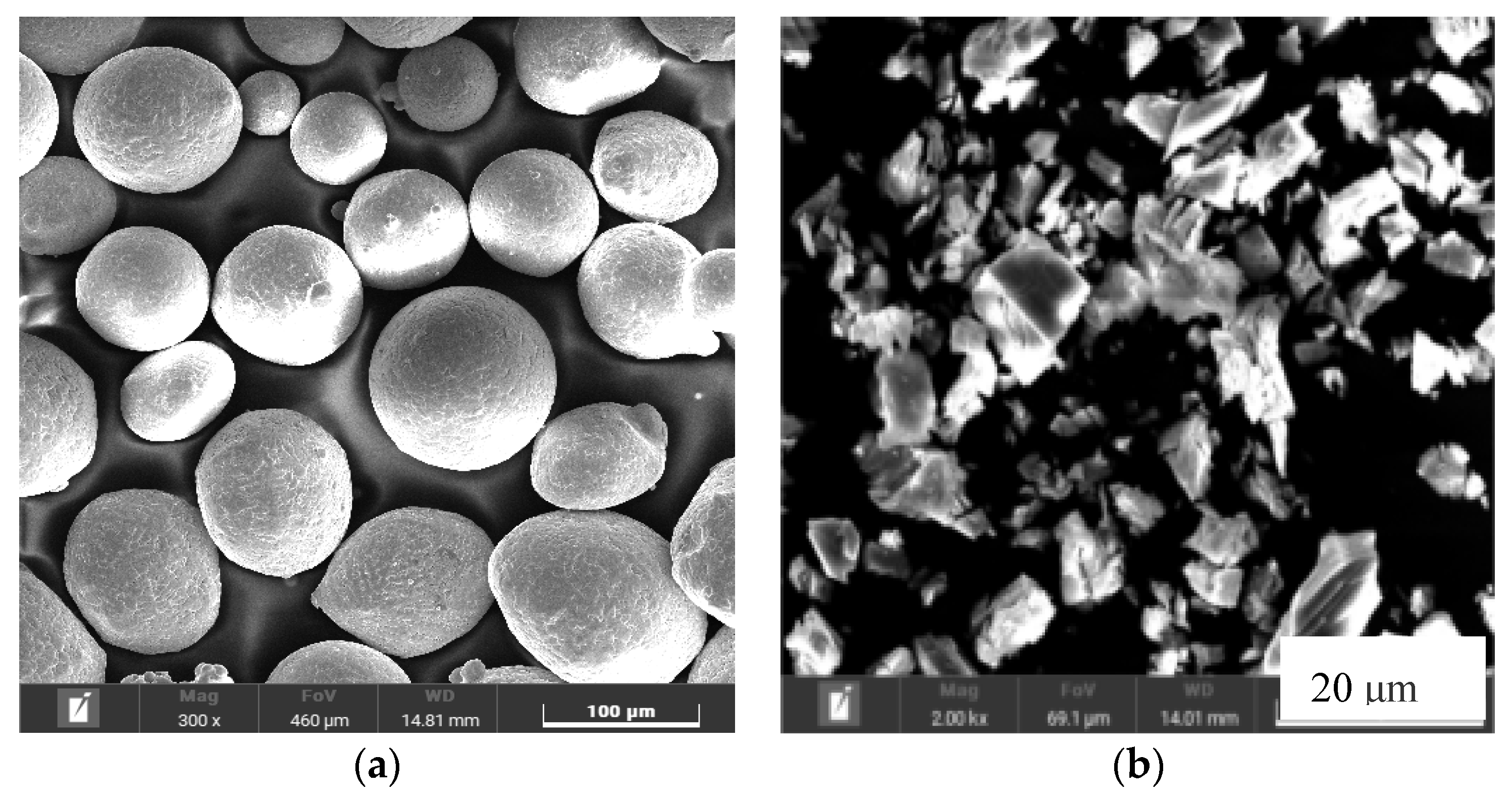
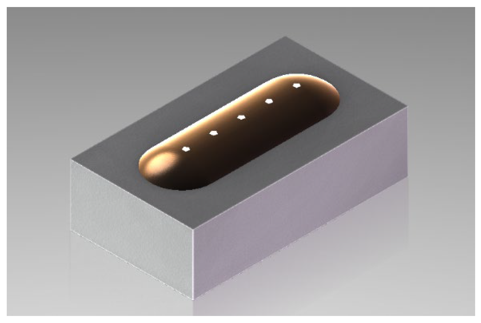
2. Materials and Methods

The low-carbon steel produced by Liuzhou Iron and Steel Group Co., Ltd, Liuzhou, China. was used as the substrate for laser cladding. Before the experiment, the matrix sample was first polished with metallography sandpaper to remove the surface rust and oxide layer, and then the oil and abrasive dust on the surface of the matrix sample were cleaned with acetone and ethanol. After that, the matrix sample was put into an ultrasonic cleaning machine and cleaned with deionized water for 30 min. Finally, the cleaned matrix sample was put into a drying oven. The temperature is set at 110 °C for 1 hour to ensure that the surface of the substrate is clean and dry.
The morphology of A100 ultra-high-strength steel powder and Y2O3 powder are shown in Figure 1. A100 ultra-high-strength steel powder is spherical, and the diameter of the powder is generally concentrated in about 60μm. The element composition of A100 ultra-high-strength steel powder was tested by EDS energy spectrum, and the test results are shown in Table 1. The laser power is 2000 W, the scanning speed is 6 mm/s, and the spot diameter is 4 mm. To enhance the plastic toughness of the laser-clad samples, Y2O3 was added to A100 powder in different amounts: 0.5 wt.%, 1.0 wt.% and 1.5 wt.%.
The phase composition of the laser-clad samples was analyzed using an X-ray diffractometer (XRD) fabricated by Rigaku. Testing parameters included a tube voltage of 40 kV, a tube current of 40 mA, a minimum irradiation diameter of 20 μm for the test focal spot, continuous scanning, a scanning angle ranging from 2θ = 20–90° and a scanning rate of 5°/min. Microstructure analysis of the cladding samples was carried out using optical microscopy (OM) and scanning electron microscopy (SEM). Specifically, BRUKER Quanta X400 and QUANTAX Flat QUAD energy dispersive spectrometers (EDS) were used to analyze and assess the composition and distribution of chemical elements within selected micro zones and routes of the cladding coatings. The cross-section microhardness of the cladding samples was tested using an HXS-1000 A type digital liquid crystal intelligent microhardness tester from Shanghai Hao Microlight Technology Co., Ltd, Shanghai, china. The microhardness test schematic diagram is shown in Figure 2; the applied load was 100 g, and the pressure holding time was 15 s. The wear resistance of cladding coatings was tested by an ML-10 friction and wear testing machine, and the friction pair material was GCr15 bearing steel. After the wear test, the worn surface morphologies of cladding coatings were observed and analyzed by SEM. The mass difference of friction samples before and after wear was measured by an analytical balance, and the wear amount was calculated.

3. Results and Discussion

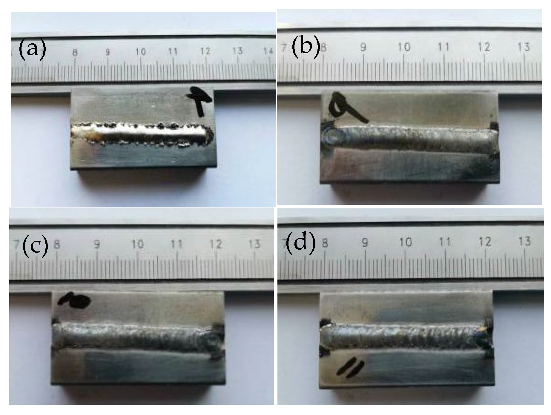
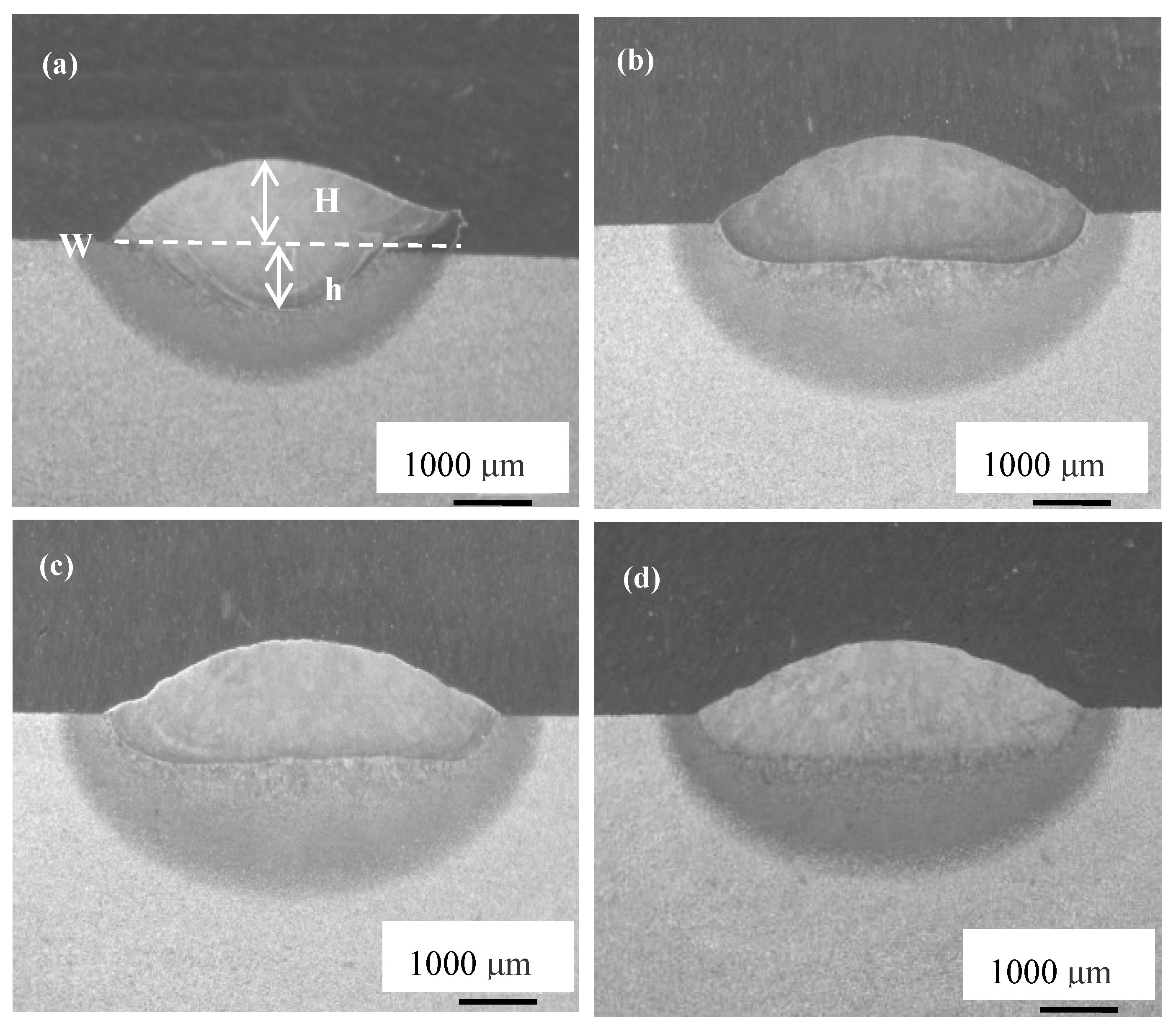
3.1. Macroscopic Morphologies of A100-Y2O3 Cladding Coatings

The surface morphologies of the A100-Y2O3 cladding coatings is shown in Figure 3. The surfaces of A100-Y2O3 cladding coatings are smooth and continuous without teardrop defects. The surface-forming quality of the cladding coatings is as expected; moreover, there are no macroscopic crack and pore defects on the surface of the cladding coatings.
The cross-section morphologies of A100-Y2O3 cladding coatings are shown in Figure 4. A100-Y2O3 cladding coatings present a protruding arc. The projection degree of the cladding coatings with Y2O3 added are smaller than that without Y2O3 added, that is to say, the wettability of the cladding coating with Y2O3 added is better than that without Y2O3 added, which indicates that Y2O3 is conducive to improving the wettability of the A100-Y2O3 cladding coatings and the substrate. A100-Y2O3 cladding coatings inside have no cracks, pores or other defects inside and are well connected with the substrate. In contrast to the A100-0%Y2O3 cladding coating, the wettability of A100-Y2O3 cladding coating on the surface of the substrate material is better, the melting height is lower, and the melting depth is significantly reduced. The melting height (H), melting depth (h) and melting width (W) of the A100-Y2O3 cladding coatings were tested and are shown in Table 2. It can be seen from Table 2 that the melting width of the coating increases significantly and that the melting height decreases after the addition of Y2O3. This shows that after the addition of Y2O3, the spreading ability of A100-Y2O3 cladding coatings on the substrate is enhanced, that is, the wettability of the A100-Y2O3 cladding coatings and the substrate is improved.

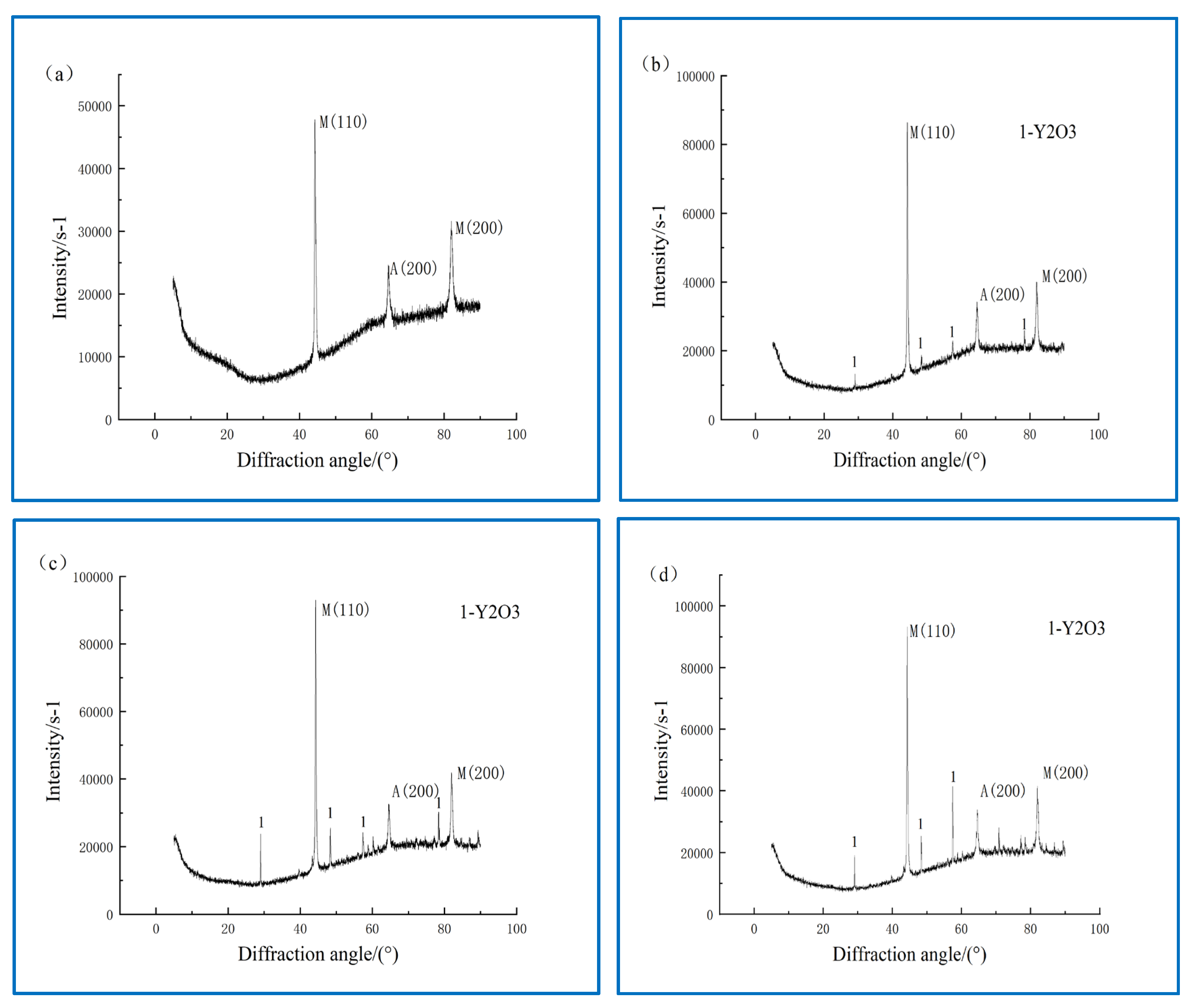
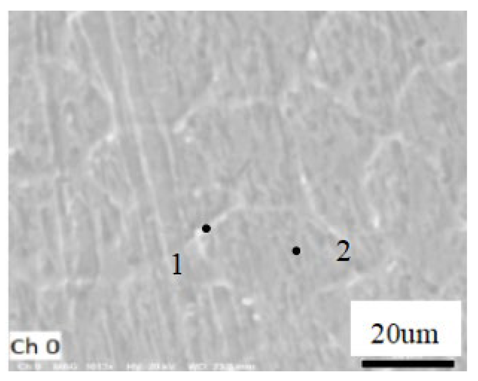
3.2. Phase Composition and Microstructure of A100-Y2O3 Cladding Coatings

The results of XRD analysis of the phase composition of A100-Y2O3 cladding coatings are shown in Figure 5. It can be seen from Figure 5 that the phases of A100-Y2O3 cladding coatings mainly include martensite, austenite and Y2O3. The results of XRD analysis show that changing the amount of Y2O3 added does not change the phase composition of the A100-Y2O3 cladding coatings.
The microstructure of A100-Y2O3 cladding coating is shown in Figure 6. The upper part of the A100-0%Y2O3 cladding coating is coarse equiaxed grain (as shown in Figure 6d), and with the addition of Y2O3 to the coating, the grains of the upper part of the A100-Y2O3 cladding coatings are obviously refined to become fine equiaxed grains (as shown in Figure 6(a1,b1,c1,d1)). The middle part of the A100-Y2O3 cladding coatings is a coarse column grain (as shown in Figure 6(a2,b2,c2,d2)). The bonding between the coating and the substrate is good, and no cracks appear at the interface (as shown in Figure 6(a3,b3,c3,d3)).
The results indicate that the grains of A100-Y2O3 cladding coating are refined compared with the coating without Y2O3. Donghe Jia et al. [19] found that Y2O3 can make the grains of the coating crumble and become fine. With the increase in Y2O3 content, the grain size of the cladding coatings becomes finer. With the addition of Y2O3 in the coatings, Y2O3 acts as the core of heterogeneous nucleation when the molten pool solidifies, thus increasing the number of nucleation and refining the grains. Jingda Liu et al. [20] also found that the addition of Y2O3 can increase the nucleation rate and refine the coating structure when laser cladding a high-entropy alloy coating on the surface of H13 steel. In the central microstructure of the A100-Y2O3 cladding coating, there are columnar grains and coarse equiaxed grains. The observed microstructure characteristics are a result of the solidification process during laser cladding. In the middle of the coating, where heat diffusion is slower, grains have sufficient time to grow after nucleation, leading to the formation of columnar grains. In contrast, at the upper part of the coating, efficient heat transfer limits grain growth after nucleation, resulting in fine equiaxed grains. The presence of fine equiaxed grains on the top of the cladding coating improves its microhardness and wear resistance. Additionally, the absence of cracks and defects, along with excellent metallurgical bonding, indicates a strong connection between the coatings and the substrates, demonstrating high overall coating quality.
Figure 7 is a high-power SEM microstructure in the middle of the A100-1.5%Y2O3 cladding coating. Surface point analysis using EDS was conducted on the A100-1.5%Y2O3 cladding coatings to examine the element distribution within these coatings, and the test points are shown in Figure 7. The EDS point test results of A100-1.5%Y2O3 cladding coatings (point 1 and point 2 in Figure 7) are shown in Table 3. As shown in Table 3, the content of Y element at 1 point is higher than that at 2 points, that is, the content of Y element at the grain boundary is higher than that inside the grain. The EDS test results of A100-1.5%Y2O3 cladding coatings exhibit that Cr, Ni, Co and Mo are mainly concentrated in the grain, while Fe is evenly distributed. Y element is mainly concentrated at the grain boundary, which indicates that Y2O3 is mainly distributed at the grain boundary. This has a napping effect on the grain boundary and is conducive to refining the grain. Xiaofeng Wan et al. [21] reported that during the laser cladding of Al-Si coatings, Y element was found to be concentrated at the grain boundaries, which inhibited grain growth by nailing the grain boundaries. This is also an important reason why Y2O3 can be a refined grain after being added to the coatings.

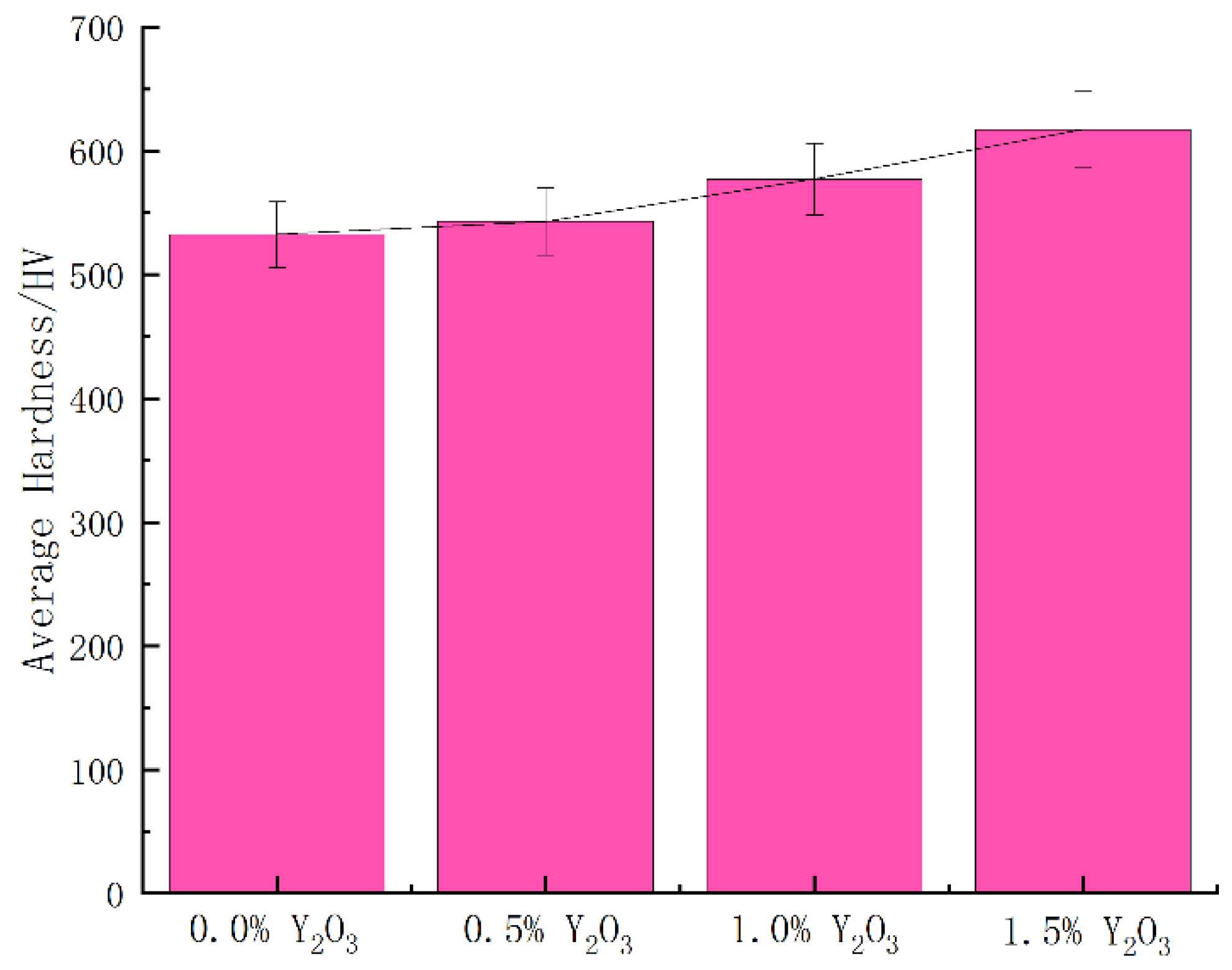
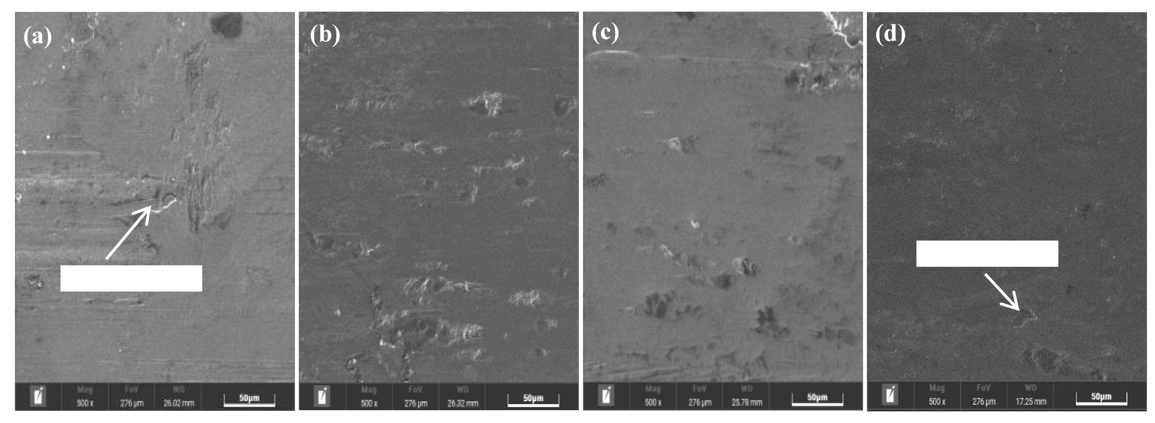
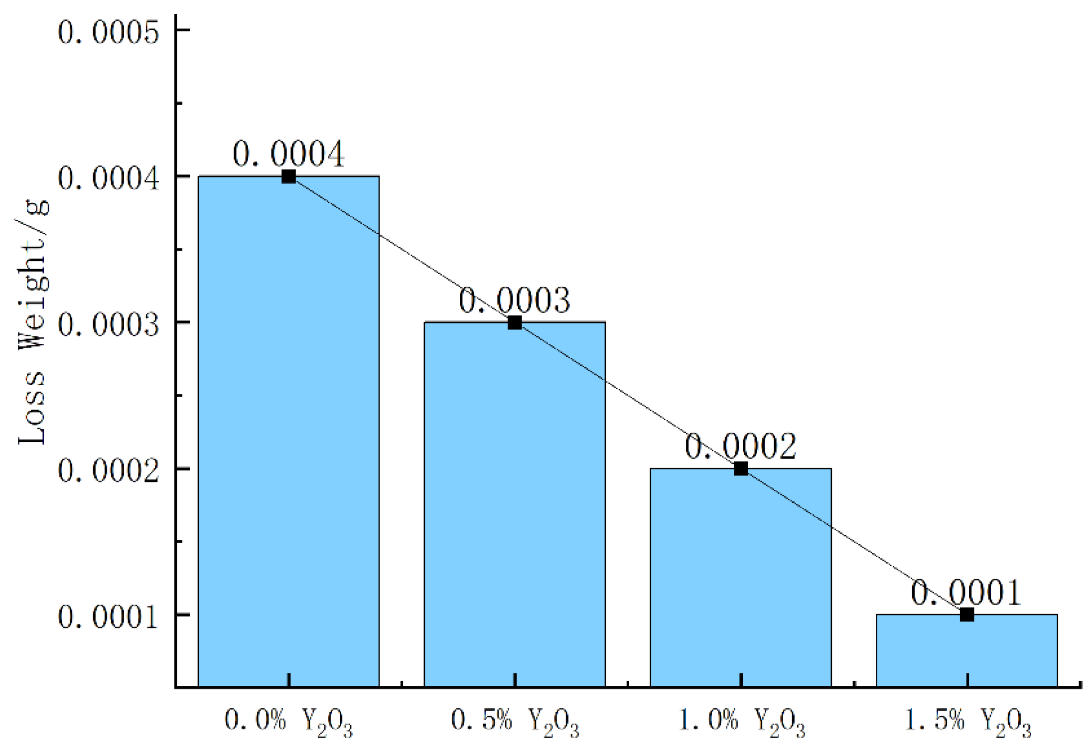
3.3. Microhardness and Wear Resistance of A100-Y2O3 Cladding Coatings

The microhardness results of A100-Y2O3 cladding coatings are shown in Table 4, and the average microhardness of A100-Y2O3 cladding coatings is shown in Figure 8. The maximum microhardness of A100-0%Y2O3 cladding coating is 552.266 HV, and when the additive amount of Y2O3 is 1.5%, the maximum microhardness of the A100-1.5%Y2O3 coating is increased by nearly 100 HV to 650.18 HV. The average microhardness value of A100-1.5%Y2O3 coating is nearly 85 HV higher than that of the A100-0%Y2O3 cladding coating. Furthermore, the average microhardness increase value of the A100-1.5%Y2O3 coating is close to the maximum microhardness increase value. It can be seen from the microhardness of the coatings that adding Y2O3 to the coatings can significantly improve the hardness of the A100-Y2O3 cladding coatings. According to the Hall–Petch relation theory, a finer grain will lead to a higher strength of the cladding coating; thus, the microhardness of the cladding coating can significantly increase with the addition of Y2O3 [22]. As can be seen from Table 4, when the amount of Y2O3 is 0.5% and 1.0%, the minimum microhardness value of the A100-Y2O3 cladding coatings is lower than the maximum microhardness value of the A100-0%Y2O3 cladding coating. When the addition of Y2O3 is 1.5%, the minimum microhardness value of the A100-1.5%Y2O3 cladding coating is higher than the maximum microhardness value of the A100-0%Y2O3 cladding coating. This shows that when the addition of Y2O3 is less than 1.5%, the increase in the microhardness of the A100-Y2O3 cladding coatings is not enough. The increase in the microhardness of the coating with Y2O3 is mainly due to fine grain strengthening caused by grain refinement and the precipitation strengthening of Y2O3 [23].
An in-depth examination of the data in Table 4 reveals interesting patterns. The variances in microhardness values for A100-0%Y2O3 and A100-1.5%Y2O3 cladding coatings are small, suggesting uniform grain sizes in these coatings. In contrast, the variances in microhardness values for A100-0.5%Y2O3 and A100-1.0%Y2O3 cladding coatings are large. This indicates that, while the grain size is refined in A100-0.5%Y2O3 and A100-1.0%Y2O3 cladding coatings compared to A100-0%Y2O3 cladding coating, the degree of grain refinement is uneven due to the relatively small amount of Y2O3. Consequently, the microhardness distribution in A100-0.5%Y2O3 and A100-1.0%Y2O3 cladding coatings is uneven, resulting in larger variances in microhardness values. Figure 9 demonstrates a gradual increase in the slope of the average microhardness value line for A100-Y2O3 cladding coatings, indicating that the impact of Y2O3 on the microhardness of A100-Y2O3 cladding coatings becomes more pronounced as the Y2O3 addition amount increases. These findings offer valuable engineering insights for enhancing the microhardness of laser-clad ultra-high-strength steel coatings by incorporating Y2O3.
In order to study the wear resistance of A100-Y2O3 cladding coatings, the wear resistance of A100-Y2O3 cladding coatings were tested by a friction and wear testing machine. The worn surface morphologies of A100-Y2O3 cladding coatings are shown in Figure 9. As can be seen from Figure 9a, the surface of the coating without Y2O3 is seriously worn, and the worn surface presents the characteristics of adhesive wear. As can be seen from Figure 9b–d, when Y2O3 is added to the A100-Y2O3 cladding coatings, the wear degree of the coatings is reduced, the worn surface of the coatings becomes relatively flat, and the wear resistance of the A100-Y2O3 cladding coatings is improved. Friction pairs wear on the surface of the A100-Y2O3 cladding coatings by moving relative to each other. Due to the plastic deformation of the materials on the A100-Y2O3 cladding coatings surface of the relative friction thermogenic, the softened material adheres to the friction pair. Under the action of the relative motion of the friction pair and A100-Y2O3 cladding coatings, the adhesive material is torn off from the coating surface, leaving the adhesive wear characteristics on the A100-Y2O3 cladding coating’s surface. The addition of Y2O3 to the coatings improves the hardness of the A100-Y2O3 cladding coatings. The A100-Y2O3 cladding coatings are not easily softened by friction and heat in the process of friction and wear. Therefore, the coatings surface material does not easily adhere to the friction pair, which improves the wear resistance of the A100-Y2O3 cladding coatings.
In addition, the nailing effect of Y2O3 at grain boundaries inhibits the deformation and migration of grains under the action of friction. With the increase in Y2O3 addition, the ability of Y2O3 to inhibit grain deformation and migration becomes stronger. Moreover, the strengthening effect of Y2O3 as a strengthening relative to the coating also improves the wear resistance of the A100-Y2O3 cladding coatings [24]. Therefore, with the increase in the addition of Y2O3, the wear resistance of the A100-Y2O3 cladding coatings improves.
The enhanced wear resistance of A100-Y2O3 cladding coatings with Y2O3 addition can be attributed to several factors:
  • Increased hardness of the coatings: Y2O3 addition improves the hardness of the A100-Y2O3 cladding coatings, making them more resistant to softening under friction and heat.
  • Nailing effect at grain boundaries: Y2O3 concentrates at grain boundaries, inhibiting grain deformation and migration during friction, which helps maintain coating integrity.
  • Strengthening effect: Y2O3 acts as a strengthening agent in the coating, further enhancing its wear resistance.
The wear weightlessness of A100-Y2O3 cladding coatings is shown in Figure 10. It can be intuitively seen from Figure 10 that the coating without Y2O3 has the most wear weightlessness. With the increase in Y2O3, the wear weightlessness of the coatings is gradually reduced. The wear resistance of A100-1.5%Y2O3 cladding coating is three times higher than that of coating without Y2O3. The wear weightlessness of the A100-Y2O3 cladding coatings is mainly caused by the friction pair tearing the A100-Y2O3 cladding coating’s surface materials. Friction pairs rub on the surface of the coating, causing the cladding coating surface materials to undergo plastic deformation by heat and friction. Under the action of friction, a part of the materials is adhered to the friction pair, and a part of the materials is fatigued and broken under the action of periodic friction to form wear chips. The addition of Y2O3 to the A100-Y2O3 cladding coatings improves the hardness and plastic deformation resistance of the coating, thus improving the wear resistance of the A100-Y2O3 cladding coatings.

4. Conclusions

Through the application of laser cladding technology, a robust A100-Y2O3 cladding coating was successfully applied to the surface of low-carbon steel, entirely free from cracks. This achievement resulted in a substantial enhancement in the wear resistance of the low-carbon steel. The key research findings can be summarized as follows:
  • Phase Composition: The A100-Y2O3 cladding coatings contain martensite, austenite and Y2O3 as the main phases. The grain structure varies within the coating, with columnar and coarse equiaxed grains in the middle and fine equiaxed grains at the top. The addition of Y2O3 results in finer grain structures.
  • Microhardness: The average microhardness of A100-0%Y2O3 cladding coating is 532.489 HV. As the Y2O3 content increases, the microhardness of the coating gradually rises. When the Y2O3 content reaches 1.5%, the average microhardness of A100-1.5%Y2O3 cladding coating reaches 617.290 HV.
  • Wear Resistance: The worn surface of A100-0%Y2O3 cladding coatings exhibits adhesive wear characteristics, indicating significant wear. However, with the addition of Y2O3, the wear resistance of the coatings improves. In particular, A100-1.5%Y2O3 cladding coating displays wear resistance three times higher than A100-0%Y2O3 cladding coating.
Overall, the addition of Y2O3 to A100 cladding coatings enhances their microhardness and wear resistance, making them significantly more durable and resistant to wear-related damage. This research demonstrates the potential for improving the wear resistance of low-carbon steel through laser cladding technology with Y2O3-modified coatings.

Author Contributions

Conceptualization, K.Z. and T.H.; Methodology, T.H.; Formal analysis, X.Z.; Investigation, Z.C.; Resources, Y.S.; Data curation, C.Z. and H.C. All authors have read and agreed to the published version of the manuscript.

Funding

This research was funded by Project of Talent Introduction and Scientific Research Start-Up Fund of Nanjing Vocational University of Industry Technology (Grant Number: 201050622RS005) and Jiangsu Province Industrial Sensing and Intelligent Manufacturing Equipment Engineering Research Center Open Fund Project (Grant Number: 201050622ZK002).

Informed Consent Statement

Not applicable.

Data Availability Statement

The data that support the findings of this study are available from the corresponding author, upon reasonable request.

Conflicts of Interest

The authors declare no conflict of interest.

References

  1. Han, T.; Xiao, M.; Zhang, Y.; Shen, Y. Effects of graphite and graphene spatial structure on the TiC crystal structure and the properties of composite coatings. Surf. Coat. Technol. 2019, 377, 124909. [Google Scholar] [CrossRef]
  2. Brnic, J.; Balos, S.; Brcic, M.; Dramicanin, M.; Krscanski, S.; Milutinovic, M.; Ding, B.; Gao, Z. Testing and Analysis of Uniaxial Mechanical Fatigue, Charpy Impact Fracture Energy and Microhardness of Two Low-Carbon Steels. Materials 2023, 16, 884. [Google Scholar] [CrossRef] [PubMed]
  3. Han, T.; Zhou, K.; Chen, Z.; Gao, Y. Research Progress on Laser Cladding Alloying and Composite Processing of Steel Materials. Metals 2022, 12, 2055. [Google Scholar] [CrossRef]
  4. Okulov, A.; Korobov, Y.; Stepchenkov, A.; Makarov, A.; Iusupova, O.; Korkh, Y.; Kuznetsova, T.; Kharanzhevskiy, E.; Liu, K. Mechanical and Structural Characterization of Laser-Cladded Medium-Entropy FeNiCr-B4C Coatings. Materials 2023, 16, 5479. [Google Scholar] [CrossRef] [PubMed]
  5. Luo, P.; Li, X.; Zhang, W.; Liang, X.; Tan, Z.; Wang, D.; Jiang, C.; Hou, J.; Sun, L. The Study of Phase Transformation Behaviors for 38MnB5Nb Ultra High-Strength Steel by CCT Curves and TTT Curves. Metals 2023, 13, 190. [Google Scholar] [CrossRef]
  6. Chen, H.; Zhao, L.; Lu, S.; Lin, Z.; Wen, T.; Chen, Z. Progress and Perspective of Ultra-High-Strength Martensitic Steels for Automobile. Metals 2022, 12, 2184. [Google Scholar] [CrossRef]
  7. Aditya, Y.N.; Srichandra, T.D.; Tak, M.; Padmanabham, G. To study the laser cladding of ultra high strength AerMet-100 alloy powder on AISI-4340 steel for repair and refurbishment. Mater. Today Proc. 2021, 41, 1146–1155. [Google Scholar] [CrossRef]
  8. Zhang, B.; He, B.; Wang, H. Microstructural investigation and mechanical performance of laser cladding repaired bainite steel with AerMet100 steel. Surf. Coat. Technol. 2022, 440, 128498. [Google Scholar] [CrossRef]
  9. Barr, C.; Da Sun, S.; Easton, M.; Orchowski, N.; Matthews, N.; Brandt, M. Influence of macrosegregation on solidification cracking in laser clad ultra-high strength steels. Surf. Coat. Technol. 2018, 340, 126–136. [Google Scholar] [CrossRef]
  10. Walker, K.; Lourenço, J.; Sun, S.; Brandt, M.; Wang, C. Quantitative fractography and modelling of fatigue crack propagation in high strength AerMet®100 steel repaired with a laser cladding process. Int. J. Fatigue 2017, 94, 288–301. [Google Scholar] [CrossRef]
  11. Rashid, R.R.; Barr, C.; Palanisamy, S.; Nazari, K.; Orchowski, N.; Matthews, N.; Dargusch, M. Effect of clad orientation on the mechanical properties of laser-clad repaired ultra-high strength 300 M steel. Surf. Coat. Technol. 2019, 380, 125090. [Google Scholar] [CrossRef]
  12. Rashid, R.R.; Nazari, K.; Barr, C.; Palanisamy, S.; Orchowski, N.; Matthews, N.; Dargusch, M. Effect of laser reheat post-treatment on the microstructural characteristics of laser-cladded ultra-high strength steel. Surf. Coatings Technol. 2019, 372, 93–102. [Google Scholar] [CrossRef]
  13. Ran, X.; Cheng, H.; Liu, D.; Zhang, S.; Tang, H.; Wang, H. Microstructure and Mechanical Properties of Plasma Arc Welding Joint for Laser Melting-Deposited AerMet100 Ultrahigh-Strength Steel. Mater. Sci. Forum 2014, 789, 424–430. [Google Scholar] [CrossRef]
  14. Zhang, D.; He, X.; Gao, Y.; Qin, B. Investigation of the Microstructure and Wear Properties of Laser Clad Al-Si Coatings Containing Different Y2O3 Contents. Coatings 2023, 13, 308. [Google Scholar] [CrossRef]
  15. Chen, T.; Wu, F.; Wang, H.; Liu, D. Laser Cladding In-Situ Ti(C,N) Particles Reinforced Ni-Based Composite Coatings Modified with CeO2 Nanoparticles. Metals 2018, 8, 601. [Google Scholar] [CrossRef]
  16. Wang, W.; Chen, Z.; Feng, S. Effect of CeO2 on Impact Toughness and Corrosion Resistance of WC Reinforced Al-Based Coating by Laser Cladding. Materials 2019, 12, 2901. [Google Scholar] [CrossRef]
  17. Chen, T.; Liu, D.; Wu, F.; Wang, H. Effect of CeO2 on Microstructure and Wear Resistance of TiC Bioinert Coatings on Ti6Al4V Alloy by Laser Cladding. Materials 2017, 11, 58. [Google Scholar] [CrossRef] [PubMed]
  18. Zhao, W.; Liu, D.; Yang, J.; Zhang, H.; Ma, A.; Zhang, X.; Ren, Z.; Zhang, R.; Dong, Y.; Ye, C. Improving plain and fretting fatigue resistance of A100 steel using ultrasonic nanocrystal surface modification. Int. J. Fatigue 2021, 148, 106204. [Google Scholar] [CrossRef]
  19. Jia, D.; Shi, W.; Zhang, H.; Wu, T.; Diao, Y.; Li, K.; Lu, C. Effects of Y2O3 Content on Wear Resistance and Corrosion Resistance of 316L/TiC Coating Fabricated by Laser Cladding. Coatings 2023, 13, 1348. [Google Scholar] [CrossRef]
  20. Liu, J.; Guan, Y.; Xia, X.; Peng, P.; Ding, Q.; Liu, X. Laser Cladding of Al0.5CoCrCuFeNiSi High Entropy Alloy Coating without and with Yttria Addition on H13 Steel. Crystals 2020, 10, 320. [Google Scholar] [CrossRef]
  21. Wan, X.; Tian, C.; Li, Y.; Zhou, J.; Qian, S.; Su, L.; Wang, L. Effect of Y2O3 Addition on Microstructure and Properties of Laser Cladded Al-Si Coatings on AZ91D Magnesium Alloy. Materials 2022, 16, 338. [Google Scholar] [CrossRef] [PubMed]
  22. Han, T.; Xiao, M.; Zhang, Y.; Shen, Y. Effect of Cr content on microstructure and properties of Ni-Ti-xCr coatings by laser cladding. Optik 2019, 179, 1042–1048. [Google Scholar] [CrossRef]
  23. Jiang, H.; Zhao, X.; Wang, D.; Zhu, Q.; Li, T.; Lei, Y. Effects of Y2O3 Addition on the Microstructure and Static Lead-Bismuth Eutectic Thermal Corrosion Behaviors of FeCrAlTiC-xY2O3 Laser Clade Coatings. Coatings 2022, 12, 1759. [Google Scholar] [CrossRef]
  24. Gao, Y.; Lu, P.; Bai, S.; Qin, B.; Zhang, D. Influence of Laser Power on Microstructure and Properties of Al-Si+Y2O3 Coating. Coatings 2023, 13, 1289. [Google Scholar] [CrossRef]
Figure 1. A100 ultra-high-strength steel and Y2O3 powder morphology. (a) A100 ultra-high-strength steel powder, (b) Y2O3 powder.
Coatings 13 01702 g001
Figure 2. Schematic diagram of A100-Y2O3 cladding coating microhardness test.
Coatings 13 01702 g002
Figure 3. The surface morphologies of the cladding coatings. (a) A100-0%Y2O3, (b) A100-0.5%Y2O3, (c) A100-1.0%Y2O3, (d) A100-1.5%Y2O3.
Coatings 13 01702 g003
Figure 4. Cross section morphologies of A100-Y2O3 cladding coatings (a) A100-0%Y2O3, (b) A100-0.5%Y2O3, (c) A100-1.0%Y2O3, (d) A100-1.5%Y2O3.
Coatings 13 01702 g004
Figure 5. XRD analysis of A100-Y2O3 cladding coatings (a) A100-0%Y2O3, (b) A100-0.5%Y2O3, (c) A100-1.0%Y2O3, (d) A100-1.5%Y2O3.
Coatings 13 01702 g005
Figure 6. Microstructures of A100-Y2O3 cladding coatings (a1) Microstructure of the upper part of A100-0.5%Y2O3 cladding coating, (a2) Microstructure of the middle part of A100-0.5%Y2O3 cladding coating, (a3) Microstructure of the lower part of A100-0.5%Y2O3 cladding coating, (b1) Microstructure of the upper part of A100-1.0%Y2O3 cladding coating, (b2) Middle microstructure of A100-1.0%Y2O3 cladding coating, (b3) Microstructure of the lower part of A100-1.0%Y2O3 cladding coating, (c1) Upper microstructure of A100-1.5%Y2O3 cladding coating, (c2) Middle microstructure of A100-1.5%Y2O3 cladding coating, (c3) Microstructure of the lower part of A100-1.5%Y2O3 cladding coating, (d1) Microstructure of the upper part of A100-0%Y2O3 cladding coating, (d2) Microstructure of the middle part of A100-0%Y2O3 cladding coating, (d3) Microstructure of the lower part of A100-0%Y2O3 cladding coating.
Coatings 13 01702 g006
Figure 7. High power SEM microstructure in the middle of the A100-1.5%Y2O3 cladding coating.
Coatings 13 01702 g007
Figure 8. The average microhardness of A100-Y2O3 cladding coatings.
Coatings 13 01702 g008
Figure 9. Worn surface morphologies of A100-Y2O3 cladding coatings (a) Worn surface topography of A100-0%Y2O3 cladding coating, (b) Worn surface topography of A100-0.5%Y2O3 cladding coating, (c) Worn surface topography of A100-1.0%Y2O3 cladding coating, (d) Worn surface topography of A100-1.5%Y2O3 cladding coating.
Coatings 13 01702 g009
Figure 10. Wear weightlessness of A100-Y2O3 cladding coatings.
Coatings 13 01702 g010
Table 1. A100 ultra-high strength steel powder element composition (wt.%).
ElementsFeCoNiCrMo
Content69.6914.3511.273.071.62
Table 2. The geometric size of the A100-Y2O3 cladding coatings.
CoatingsH (μm)h (μm)W (μm)W/H
A100-0%Y2O3110598247624.31
A100-0.5%Y2O3108070551674.78
A100-1.0%Y2O398375759866.09
A100-1.5%Y2O399774559145.93
Table 3. EDS point analysis of elements in A100-1.5%Y2O3 cladding coating.
PointFeCoNiCrMoY
168.2312.8911.044.482.181.18
273.4812.7310.153.030.350.26
Table 4. Microhardness results of A100-Y2O3 cladding coatings.
SamplesMax ValueMin ValueAverageVariance
A100-0%Y2O3552.266494.131532.48926.396
A100-0.5%Y2O3589.803507.176542.20433.166
A100-1.0%Y2O3630.387525.481577.31435.169
A100-1.5%Y2O3650.180570.446617.29026.213
Disclaimer/Publisher’s Note: The statements, opinions and data contained in all publications are solely those of the individual author(s) and contributor(s) and not of MDPI and/or the editor(s). MDPI and/or the editor(s) disclaim responsibility for any injury to people or property resulting from any ideas, methods, instructions or products referred to in the content.

