Article

Design and Fabrication of Nanofiber-Coated Antenna with Electrospun Polyacrylonitrile (PAN) for Tissue Cancer Ablation

1
Biomedical Engineering Department, Faculty of Engineering, Minia University, Minia 61519, Egypt
2
Chemical Engineering Department, Faculty of Engineering, Minia University, Minia 61519, Egypt
3
Mechanical Engineering Department, King Saud University, Riyadh 11421, Saudi Arabia
4
Center of Excellence for Research in Engineering Materials (CEREM), King Saud University, Riyadh 11421, Saudi Arabia
5
Department of Mechanical & Energy Systems Engineering, Faculty of Engineering and Informatics, University of Bradford, Bradford BD7 1DP, UK
*
Author to whom correspondence should be addressed.
Coatings 2023, 13(10), 1767; https://doi.org/10.3390/coatings13101767
Submission received: 7 September 2023 / Revised: 2 October 2023 / Accepted: 11 October 2023 / Published: 13 October 2023
(This article belongs to the Special Issue Nanostructures for Biomedical Applications)

Abstract

:
Hepatocellular carcinoma (HC) is a common liver cancer often associated with chronic liver diseases such as hepatitis B and C-induced cirrhosis. Multiple treatments are available, including microwave ablation (MWA), which has proven effective. This is attributed to its proved ability to eliminate liver tumors with a successful rate of more than 85%. However, in order to maintain healthy tissues and establish good ablation practicability, the temperature involved should be controlled. This can be achieved by monitoring different parameters including thermal conductivity, heat capacity, and blood perfusion. For this purpose, an antenna probe is usually employed to localize heat distributions and identify heating efficiency. Many types and shapes of antenna probes for MWA have been reported in different studies. Thus, in the current study, a numerical model is established to investigate the performance of the antenna based on its shape. A finite element model (FEM) was developed to examine the specific absorption rate (SAR), distribution of temperature, and coefficient of reflection. Closed and conventional single-slot antennas were targeted via this model. The antenna was then designed to have a reflection coefficient lower than 10 dB and heating of a spherical shape profile. The findings of the study can aid in determining the optimal parameters required for the highest effectiveness of MWA in the treatment of HC at early stages with the lowest amount of invasiveness and collateral harm.

Graphical Abstract

1. Introduction

Among the different non-surgical treatments for liver tumors, thermal ablation is a well-studied method [1,2]. Thermal ablations can be categorized into different modalities including MWA, which is becoming a cornerstone in the treatment for the tumors of the liver [3]. The most common approach is the imaging-guided percutaneous insertion of a microwave antenna into the target tissue. The antenna works as a radiation medium through which to transfer microwave energy into the targeted tissue where heat is released as result of the oscillation of polar molecules, protein, and water out of phase [4].
MWA as a type of thermal ablation has the ability to destroy cancer cells by raising the temperature above the physiologically normal threshold while causing little harm to neighboring tissues. This effectiveness results from the creation of larger and more uniform ablation zones in a shorter time and fewer treatment steps [5,6]. The rapid fluctuation of the electromagnetic field, throughout the MWA thermal ablation process, resulted in a friction and triggered the heating up of the molecules of water in soft tissues adjacent to the field source [4,7]. Moreover, MWA has a lower susceptibility to being impacted by heat transmission due to vascular-mediated cooling. This is because the heating of tissues to a relatively high temperatures is still achievable. The source of the microwave fields, which are in fact, the currents passing through the antenna, are affected by the surrounding tissues, resulting in unpredictable ablation zones and antenna performance. Because ground pads are not necessary during MWA, it is possible that large tumors can be treated concurrently using multiple antennas. This is accomplished through utilizing the use of a very complex design of antenna, which employs diverse mechanisms to control heat, field, and wavelength [8].
Antenna construction has a significant impact on its functioning, especially when heating is reversed down the antenna shaft. Due to the lack of a needle with acceptable mechanical qualities such as puncture force, toughness, and rigidity, the cables used for the construction of all types of antennas are simply semi-rigid. This is results in a lower suitability to therapeutic percutaneous puncture. Despite the fact that MWA allows for open, laparoscopic, or percutaneous surgical techniques to be used in therapy, percutaneous intervention guided via imaging is clinically more common, taking advantage of its lower invasion of the patient [9]. Thus, designing an antenna with exceptional mechanical properties is a vital requirement for percutaneous treatments using MWA.
An antenna’s design varies based on specific applications, and often involves coating techniques to tailor it for particular purposes. For instance, Mahdi et al. [10] employed a graphene-coated dielectric resonator antenna (DRA) to investigate human retinal photoreceptors, showcasing its suitability to the vision spectrum. In another approach, Moghadasi et al. [11] utilized a graphene-coated nano-aperture biosensor, achieving dual-band characteristics and enhanced electric field enhancement, enhancing sensitivity. Additionally, Zarrabi et al. [12] introduced a cross nano-aperture nanoantenna for mid-infrared biosensing, improving transmittance and the Q-factor through the incorporation of graphene and nano-chain elements. These studies exemplify how an antenna’s design can be adapted to various applications, enhancing its performance and versatility.
Radjenović et al. [13] developing and testing a three-dimensional model, focusing on early stage hepatocellular carcinoma treatment using MWA. This research highlights the significance of incorporating temperature-dependent factors such as heat capacity, thermal conductivity, and blood perfusion in ablation calculations for preserving healthy tissue effectively. The study demonstrates that the temperature profile in MWA is primarily governed by the heat-source distribution, with damage zones concentrated around the antenna slots and tip, leading to an extension of necrotic tissue primarily within the tumor, minimizing collateral damage to surrounding tissue. In another exploration, by Farina et al. [14], the dielectric properties of human lung tissue, including neoplastic and non-neoplastic lung tissue, were rigorously assessed for their relevance to microwave ablation applications. Notably, lung tumors exhibited significantly higher dielectric properties, making them more conducive to microwave thermal ablation, which has important implications for the design of minimally invasive ablation applicators. Recently, Paré et al. [15] introduced a novel microwave-assisted tissue ablation approach incorporating a chemical ablation agent at the emission point of the microwave antenna. The study highlights the potential of this dielectric-based method to enhance precision and reduce collateral damage in minimally invasive interventions, offering a versatile and promising approach for tissue treatment.
This study established a 2D axial-symmetric model for thermal microwave ablation. A novel antenna structure was developed using electromagnetic simulations to assess the temperature distribution, specific absorption rate, and antenna reflection coefficient. The simulations encompassed the presence of blood perfusion and water for a 2.45 GHz antenna implanted in the tumor. Furthermore, the influence of temperature on the thermal and dielectric properties of both malignant and healthy liver tissues was investigated. Through these simulations, power dissipation, the temporal evolution of temperature, and the extent of tissue necrosis resulting from elevated temperatures were estimated.

2. Antenna Design

Because of its simulation capabilities, COMSOL Multiphysics is particularly well-suited to studying the heating by electromagnetic in a variety of engineering applications. The COMSOL Multiphysics software (https://www.comsol.com/) includes finite element modeling packages (FEM), which enables tools to create and simulate the geometrical properties of the antenna, define the biological characteristics of materials, and determine the appropriate meshing, including the physics of the component such as heat transfer and electromagnetics, and it is regarded as an excellent platform for evaluating results [16,17].
Thin coaxial wires ranging in diameter from 1.5 to 3 mm are usually used to construct antennas for MWA ablation. Several researchers are collaborating to create an antenna capable of significant tumor ablation while generating minimal retrograde heating that takes place along the antenna shaft. The aim is to design a viable antenna to be used in clinical MWA for tumor therapy.
Microwave coagulation therapy involves inserting a small microwave antenna into a cancerous tissue. The microwaves cause the tumor to coagulate, killing cancer cells. The utilization of a thin coaxial-slot antenna in this coagulation therapy allows calculations of the SAR, the radiation field, and the temperature field in liver tissue to be carried out. The SAR represents the ratio of the power of absorbed heat to the density of the tissue. The functioning quality of the ablation antenna can be evaluated via measurements of the antenna’s size, shape, and ablation efficiency. Achieving heating that takes place in a spherical pattern and a reflection coefficient lower than 10 dB was considered at the stage of proposing and developing the construction of the antenna.
The fast-paced electromagnetic field oscillation during MWA triggered the molecules of water in the soft tissues adjacent to field source to generate frictional heat. Additionally, the microwave field source, which is the currents in the antenna, is influenced by the surrounding tissues, resulting in unpredictable ablation zones and antenna performance. To accomplish this task, an advanced antenna design that employs a mechanism that controls the thermal properties, field, and wavelength [8] distinctively is used. Because antennas are typically mechanically and geometrically complicated, the properties of the tissue and electromagnetic material are required for modeling.
The antenna’s geometry is divided into four domains. These are the dielectric domain, the catheter domain, the air domain, and the liver domain. These domains are depicted in Figure 1.

3. Experimental and Simulation

3.1. Modeling and Simulation

The mathematical model of microwave ablation simulation is made up of three major components, including the applicator (antenna probe) model that generates a microwave field in the tissue, in addition to another part describing the heat distribution throughout the tissue, incorporating sources, sinks and phase changes. In this component, the heat source in the current model is microwave radiation, while heat sinks are simulated via the blood perfusion term in the equation of heat transfer. The final section looks at how heat affects tumor cells and how to destroy them. All of these ablation model elements are dependent on the material properties that are selected based on various attributes of the targeted tissue.
Due to the complexity of the mechanics and geometry of the antenna, the simulations rely on the precision of the utilized properties of both electromagnetic material and tissue. Thus, the following equations [18,19] describe antenna-driven microwave wave propagation through tissue:
× μ r 1 × E k 0 2 ϵ r j σ ω ϵ 0 E = 0
where ω represents the angular frequency, k 0 accounts for the vacuum propagation constant that can be obtained via k 0 = ω c 0 , E refers to the electric field vector, and σ is the symbol used to include the electrical conductivity of the tissue. Additionally, ϵ 0 represents the vacuum dielectric constant, ϵ r refers to relative permittivity, and μ r is the symbol for tissue permeability.
Additionally, an effective explanation of heat transmission as part of the MWA process was achieved via the equation of Pennes, a bioheat equation:
ρ c T t = × k T + ρ b W b c b T b T + Q e x t + Q m
where tissue temperature, heat capacity, and density are represented by T, c, and ρ, respectively, while those with the subscript b stand for blood, including W b , which represents its perfusion rate. Moreover, Qm is the metabolism heat source that is small enough to be neglected; however, Qext represents the external heat source, explaining the coupling with the electromagnetic field and which can be obtained via [20]:
Q e x t = σ E 2 2
At a steady state, about 78% of liver tissue mass is water; however, when the temperatures go higher than 100 °C, water will evaporate, reducing its content to less than 20%, causing a significant deviation in the dielectric properties of tissue, and resulting in increased microwave penetration [21,22]. Because water comprises a large portion of liver tissue, tissue thermal properties can be considered to be largely similar to the thermal properties of water with variations depending on temperature and water concentration [23]. To account for the internal evaporation of water in the bioheat equation, we can substitute an effective value, c′, with that for specific heat, c, as shown via the following relation [20]:
c = c α ρ W T
In this relation, α represents the latent heat constant of water, where its value is 2260 (kJ/kg), showing that biological damage is affected by temperature and time.
In addition to the relationship between the temperature and the dielectric characteristics of tissues, the numerical simulation includes blood perfusion, heat capacity, and thermal conductivity. The selected microwave frequency and input power for this numerical simulation was 2.45 GHz and 20 W, respectively. It has been found through reviewing the literature that a healthy liver, tumoral tissue, and blood can be characterized using lists of parameters such as that shown in Table 1.

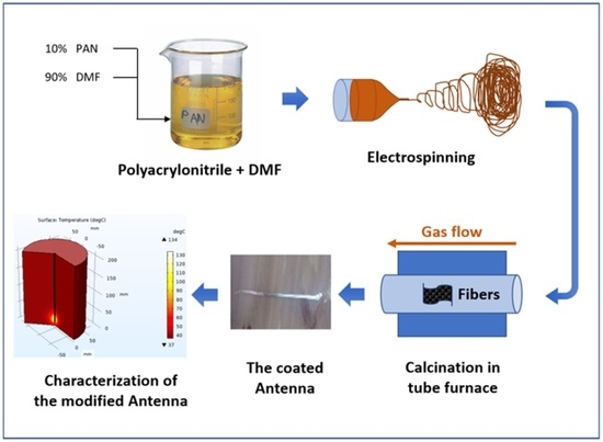
3.2. Antenna Fabrication

The coaxial cable consists of 3 main components, as shown in Figure 2. First, it consists of an inner conductor made of copper with a diameter of 0.5 mm. Second, it consists of a dielectric material, polyacrylonitrile “PAN”, which comes in power form, as shown in Figure 2b. Third, it consists of a solvent used with the dielectric PAN, NN-dimethylformamide (DMF). Fourth, it consists of an outer conductor that comes in the form of copper wire with a diameter of 3 mm.
To fabricate the microwave antenna from scratch, 3 steps were conducted. Firstly, to improve the properties of both the inner and outer conductor, an electroplating technique was used to deposit graphene onto the surface of the copper wires. Then, based on the COMSOL simulation program’s design, the inner conductor was isolated from the outer conductor. In addition, the inner conductor was precisely centered in the outer conductor. Consequently, an electrospinning technique was utilized. Eventually, a calcination process was conducted to remove volatile substances.

3.2.1. Electroplating Process

The overall electroplating process employs an electrolytic cell. This involves the application of a negative charge to the metal. The metal is then immersed in a solution containing metal salts. This metal salt contains so-called electrolytes that contain ions with positive charges. Thus, attraction between the two metals is created by negative charges and positive ones. In this study, the copper wire is a cathode, while the anode is usually made of a graphene or platinum and could be a sacrificial or an inert one. As shown in Figure 3, the positive ions of graphene are attracted to the walls of the outer and inner copper conductors and become plated. The anode in the process is graphene oxide, and the cathode is made of copper conductors. In a graphene-containing solution, electrons flow from the anode to the cathode. Figure S1 (in the Supplementary Materials) depicts the electroplating process for the inner and outer copper conductors, as well as the conductor after electroplating.

3.2.2. Electrospinning Process

Electrospinning is a straightforward and comprehensive method for producing extremely fine fibers with diameters from several micrometers down to 2 nm. A variety of materials such as polymer, composite, and ceramic [24] are utilized in this procedure.
The electrospinning apparatus shown in Figure 4 was designed with several key components. It includes a high-voltage power supply source for delivering a maximum DC output of 50 kV, a solution reservoir, a syringe with a small-diameter metallic needle, and a fixed plate or rotary platform as a conductive collector [25,26]. To initiate the electrospinning process, the prepared PAN gel was poured into a plastic syringe with a 20 mL capacity. This syringe, loaded with the PAN gel, was then connected to the electrospinning device, as depicted in Figure 4. The electrospinning process was carried out using three fundamental components: a high-voltage source operating at 30 kV, a syringe with the needle diameter of 0.1 mm, with a flow rate of 0.2 mL/h, and a collecting drum set to a low rotation speed ranging from 70 to 90 rpm.
After PAN and DMF mixed in a 10% weight ratio, they were dissolved. The agitation of the solution was then conducted at room temperature for 2 h, followed by 1 h of ultrasonic treatment and stirring until uniformity was achieved. The homogeneous precursor solution was placed in the electrospinning system in a 10 mL plastic syringe. A PAN solution, held at the end of a capillary tube via surface tension, was exposed to an electric field inducing an electric charge up on the surface of the solution. Once a critical value of about 15 KV was reached via the electric field that was applied, surface tension forces were surpassed by revolting electrical forces. A jet of solution-carrying charges was ejected from the tip of a Taylor cone. Unstable and sudden jet whipping occurred in the area between the collector and the capillary tip, evaporating DMF and forming PAN. The drum was filled with spun polymeric nanofibers, which were then placed in a 60 °C incubator overnight before further calcination. Figure S2a (in the Supplementary Materials) depicts a preparation process schematic, while Figure S2b (in the Supplementary Materials) depicts a real image of PAN nanofibers on the inner and outer conductors.

3.2.3. Calcination Process

The calcination process is divided into two stages: stabilization and carbonization [27]. During the stabilization stage, a furnace in the air set to 250 °C for 1 h was used with the aim of achieving the specific structure of an infusible pecking-order polymer. The purpose of conducting this step was to prevent the melting of the samples at high temperatures [7]. During the carbonization stage, an inert gas, namely argon, was introduced into the system at a 400 mL/min flowrate and an increasing heating rate temperature of 5 °C/min towards the desired temperature, which in this case was 900 °C, for 60 min. Additionally, this was carried out for the purpose of removing the air from the tube due the fact that oxygen presence at high temperatures could lead to damage to the samples. Moreover, different structures of carbon nanofibers such as graphite or amorphous carbons are obtainable at temperatures higher than 600 °C.
According to the literature review [28,29,30], if the calcination atmosphere is inert gas, then the diameters of the fibers decrease as the temperature rises. Furthermore, during higher-temperature calcination processes there is an increase in the atomic percentages of carbon materials, demonstrating that additional non-carbon components are separated [31]. Figure S3 (in the Supplementary Materials) depicts the outer copper conductor after calcination.

3.2.4. Inner Conductor Centering

As mentioned before, the electrospinning technique is a way center inner conductor within the outer one. The internal conductor was coated with a layer of PAN nanofibers until its diameter reached 2.5 mm (equal to the space between the inner conductor and the inner wall of the outer conductor) over the inner conductor. In this step, calcination was not performed, and the insulating properties of PAN were needed to isolate the inner conductor from the outer conductor. Figure S4 (in the Supplementary Materials) shows the inner conductor after the electrospinning process.
To create the final shape of the antenna, the monopole single-slot antenna structure was selected. A 1 mm slot needed to be cut in the outer conductor of the coaxial cable, 5 mm away from the end of the cable. Consequently, a very thin metal blade was used to maintain the accuracy of dimensions. A point of contact between the inner and outer conductors was introduced by wrapping another copper wire around that point to ensure that the two conductors touched along the diameter of the outer conductor. Finally, a thin layer of fibers was deposited to the outer conductor only for decorative purposes. Figure S5 (in the Supplementary Materials) illustrates the final shape of the proposed antenna.

4. Results and Discussion

4.1. Nanofiber Coating Characterization

Figure 5 displays SEM images depicting electrospun PAN nanofibers at different magnifications. These nanofibers exhibited a random distribution, forming a fibrous tissue. Notably, the electrospun nanofibers displayed a range of fiber diameters, with their morphology and average diameter spanning from approximately 100 to 200 nm.

4.2. Simulation Results

Figure 6 and Figure 7 show the results of a 2D axial-symmetric diagram of liver tissue subjected to a microwave frequency of 2.45 GHz and an input power of 20 W. Model-generated temperature distributions are displayed. Calculations were performed at a frequency of 2.45 GHz, an ablation period of 600 s, and an input power of 20 W to determine the appropriate value of the input power that causes tumor ablation. The isocontours associated with a fraction of damage equal to one can be used to calculate the optimal input power that results in the least amount of healthy tissue damage. The isocontour that best suits the necrotic tissue corresponds to an input power of 20 W.
The density of microwave power adsorbed in tumoral liver tissue during MWA at 2.45 GHz and a 20 W input power at the end of the 600 second ablation procedure was determined. A microwave field oscillates rapidly, causing polar molecules, primarily of water, to rotate and absorb some electromagnetic energy. The absorbed power density is greatest near the antenna and diminishes with distance. The antenna’s energy is converted into heat, which kills cancer cells as it passes through the tissue. The excitation of polar water particles generates the majority of the heat, with ionic polarization accounting for only a small portion of the total heat generated. The heated zone is nearly spherical in shape and completely surrounds the tumoral tissue. The ablation period and input power are chosen to heat only a small area of healthy tissue around the tumor [32].
When absorbed energy is converted into thermal energy, the tissue temperature rises. Blood perfusion limits the size of the heated area. The temperature rises in time with ablation, peaking at around 134 °C after 600 s. As shown in Figure 8.
The graph in Figure 9b depicts the temperature dependence over time at four test points (A, B, C, and D). A similar tendency of all test points is evident as shown via all the curves. The temperature in channel D (near the heating center) quickly increased to around 70 degrees Celsius after 70 s, and then steeply increased to 105 degrees Celsius after 600 s. In contrast, after 600 s, channel C, which is the furthest away from the antenna, has the lowest temperature of around 43 °C.
It is clear from Figure 10 that the concentration of damage zones is always around either the antenna’s tip or slots, but the reverse heating effect is smaller. Thermally ablative devices cause the necrosis of tissues due to them having two distinct heating zones, known as an active heating zone and a passive heating zone. The active heating zone appears closest to the device, where energy intensity is high and tissue absorption is rapid [32]. The passive zone, on the other hand, is located outside the active zone, away from the ablation device, and has a lower energy intensity.
The completion time for necrotic tissue is shown in Figure 11 below at four test points (A, B, C, and D). For test sites A, B, and D, tumor damage gradually increases at the start of the ablation. Subsequently, it reaches a saturation region, representing the tumor necrosis completion time. Point D has the quickest tumor necrosis completion time, whereas point C has incomplete tumor necrosis.

4.3. Testing the Proposed and Fabricated Antenna

The S11 reflection coefficient in dB, which represents the amount of power reflected back from a system, can vary depending on the specific application and desired performance. A lower value of S11 indicates a better impedance match and reduced power reflection. However, the acceptable range for S11 can differ based on system requirements and design specifications. For instance, in microwave systems, a common target for S11 may be −10 dB or lower, indicating a reflection of less than 10% of the incident power. At −10 dB, approximately 90% of the power is transmitted or absorbed by the device or system, with only around 10% being reflected.
In this study, we connected a coated antenna to a VNA setup and configured the sweep parameters as follows: starting at 2 GHz and ending at 5 GHz, until the desired S11 reflection coefficient of −27.877 dB was reached. This resulted in a significant improvement of over 200% in the reflection efficiency.

5. Conclusions

This study delves into the treatment of early-stage hepatocellular carcinoma using microwave ablation through comprehensive simulation studies. To achieve this, we developed and rigorously assessed a complete three-dimensional model using the finite element method within the COMSOL Multiphysics platform. This model accounted for a realistic representation of liver tumor exposure to radiation from a single-slot microwave antenna operating at 2.45 GHz, incorporating data on biological materials. The simulation results unveiled that the symmetric simulation of the ablation process yielded optimal operating parameters for this intricate antenna–tumor combination, with an input power of 20 W and an ablation time of 600 s. It is worth noting that varying antenna types or tumor shapes would necessitate distinct operating parameters. To ensure the preservation of healthy tissue, precise ablation time determination must consider temperature-dependent factors such as heat capacity, thermal conductivity, and blood perfusion. The efficiency of microwave ablation hinges significantly on the heat source distribution, which predominantly governs the temperature profile. During ablation, the temperature surges and peaks in proximity to the microwave antenna slot. For different antennas or tumor shapes, tailored surgical techniques would be a requisite. Post-saturation, the influence of diffusion and heat conduction due to blood perfusion becomes prominent. Consequently, damage zones are concentrated primarily near the antenna’s tip and slot, resulting in nearly spherical temperature distributions. The extension of necrotic tissue occurs predominantly within the tumor, with only a minimal impact on the surrounding healthy tissue, underscoring the precision and efficacy of microwave ablation as a therapeutic approach.

Supplementary Materials

The following supporting information can be downloaded at https://www.mdpi.com/article/10.3390/coatings13101767/s1.

Author Contributions

Conceptualization, M.S.A., A.M. and H.S.A.; Methodology, M.S.A. and A.M.; Software, M.S.A., A.M., S.M.A. and M.A.S.; Validation, M.S.A., A.M., A.F., S.M.A., M.A.S. and H.S.A.; Formal analysis, A.M., A.F., S.M.A. and M.A.S.; Investigation, M.S.A., A.M., A.F., M.A.S. and H.S.A.; Resources, H.S.A.; Data curation, M.S.A., A.M., A.F., S.M.A. and M.A.S.; Writing—original draft, M.S.A., A.M., A.F., S.M.A. and H.S.A.; Writing—review & editing, H.S.A.; Visualization, S.M.A.; Supervision, H.S.A.; Funding acquisition, H.S.A. All authors have read and agreed to the published version of the manuscript.

Funding

This research was funded by Deputyship for Research and Innovation, Ministry of Education in Saudi Arabia, for funding this research work through project no. IFKSUOR3-074-3.

Institutional Review Board Statement

Not applicable.

Informed Consent Statement

Not applicable.

Data Availability Statement

The data that support the findings of this study are available from the corresponding author upon reasonable request.

Acknowledgments

The authors extend their appreciation to the Deputyship for Research and Innovation, Ministry of Education in Saudi Arabia, for funding this research work through project no. IFKSUOR3-074-3.

Conflicts of Interest

The authors declare no conflict of interest.

References

  1. Bertram, J.M.; Yang, D.; Converse, M.C.; Webster, J.G.; Mahvi, D.M. A Review of Coaxial-Based Interstitial Antennas for Hepatic Microwave Ablation. Crit. Rev. Biomed. Eng. 2006, 34, 187–213. [Google Scholar] [CrossRef] [PubMed]
  2. Livraghi, T.; Meloni, F.; Di Stasi, M.; Rolle, E.; Solbiati, L.; Tinelli, C.; Rossi, S. Sustained complete response and complications rates after radiofrequency ablation of very early hepatocellular carcinoma in cirrhosis: Is resection still the treatment of choice? Hepatology 2008, 47, 82–89. [Google Scholar] [CrossRef] [PubMed]
  3. Meloni, M.F.; Chiang, J.; Laeseke, P.F.; Dietrich, C.F.; Sannino, A.; Solbiati, M.; Nocerino, E.; Brace, C.L.; Lee, F.T. Microwave ablation in primary and secondary liver tumours: Technical and clinical approaches. Int. J. Hyperth. 2017, 33, 15–24. [Google Scholar] [CrossRef] [PubMed]
  4. Simon, C.J.; Dupuy, D.E.; Mayo-Smith, W.W. Microwave ablation: Principles and applications. Radiographics 2005, 25 (Suppl. S1), S69–S83. [Google Scholar] [CrossRef]
  5. Facciorusso, A.; El Aziz, M.A.A.; Tartaglia, N.; Ramai, D.; Mohan, B.P.; Cotsoglou, C.; Pusceddu, S.; Giacomelli, L.; Ambrosi, A.; Sacco, R. Microwave Ablation Versus Radiofrequency Ablation for Treatment of Hepatocellular Carcinoma: A Meta-Analysis of Randomized Controlled Trials. Cancers 2020, 12, 3796. [Google Scholar] [CrossRef] [PubMed]
  6. Abdelaziz, A.O.; Nabeel, M.M.; Elbaz, T.M.; Shousha, H.I.; Hassan, E.M.; Mahmoud, S.H.; Rashed, N.A.; Ibrahim, M.M.; Abdelmaksoud, A.H. Microwave ablation versus transarterial chemoembolization in large hepatocellular carcinoma: Prospective analysis. Scand. J. Gastroenterol. 2015, 50, 479–484. [Google Scholar] [CrossRef]
  7. Poggi, G.; Tosoratti, N.; Montagna, B.; Picchi, C. Microwave ablation of hepatocellular carcinoma. World J. Hepatol. 2015, 7, 2578. [Google Scholar] [CrossRef] [PubMed]
  8. Kuroda, H.; Nagasawa, T.; Fujiwara, Y.; Sato, H.; Abe, T.; Kooka, Y.; Endo, K.; Oikawa, T.; Sawara, K.; Takikawa, Y. Comparing the Safety and Efficacy of Microwave Ablation Using ThermosphereTM Technology versus Radiofrequency Ablation for Hepatocellular Carcinoma: A Propensity Score-Matched Analysis. Cancers 2021, 13, 1295. [Google Scholar] [CrossRef] [PubMed]
  9. Ahmed, M.; Brace, C.L.; Lee, F.T.; Goldberg, S.N. Principles of and advances in percutaneous ablation. Radiology 2011, 258, 351–369. [Google Scholar] [CrossRef]
  10. NoroozOliaei, M.; Riazi Esfahani, H.; Abrishamian, M.S. Graphene coated dielectric resonator antenna for modeling the photoreceptors at visible spectrum. Heliyon 2022, 8, e09611. [Google Scholar] [CrossRef]
  11. Moghadasi, M.N.; Sadeghzadeh, R.A.; Toolabi, M.; Jahangiri, P.; Zarrabi, F.B. Fractal cross aperture nano-antenna with graphene coat for bio-sensing application. Microelectron. Eng. 2016, 162, 1–5. [Google Scholar] [CrossRef]
  12. Zarrabi, F.B.; Naser-Moghadasi, M.; Heydari, S.; Maleki, M.; Arezomand, A.S. Cross-slot nano-antenna with graphene coat for bio-sensing application. Opt. Commun. 2016, 371, 34–39. [Google Scholar] [CrossRef]
  13. Radjenović, B.; Sabo, M.; Šoltes, L.; Prnova, M.; Čičak, P.; Radmilović-Radjenović, M. On Efficacy of Microwave Ablation in the Thermal Treatment of an Early-Stage Hepatocellular Carcinoma. Cancers 2021, 13, 5784. [Google Scholar] [CrossRef] [PubMed]
  14. Farina, L.; Ruvio, G.; Shatwan, R.; Shalaby, A.; O’Halloran, M.; White, A.; Soo, A.; Breen, D.; Lowery, A.; Quinn, A.M. Histology-Validated Dielectric Characterisation of Lung Carcinoma Tissue for Microwave Thermal Ablation Applications. Cancers 2023, 15, 3738. [Google Scholar] [CrossRef] [PubMed]
  15. Paré, J.R.J.; Bélanger, J.M.R.; Cormier, G.; Foucher, D.; Thériault, A.; Savoie, J.C.; Rochas, J.F. Microwave-Assisted Chemical Ablation (MA-CA): A Novel Microwave-Assisted Tissue Ablation Procedure—Preliminary Assessment of Efficiency. Appl. Sci. 2023, 13, 7177. [Google Scholar] [CrossRef]
  16. Heat Transfer Modeling Software for Analyzing Thermal Effects. Available online: https://www.comsol.com/heat-transfer-module (accessed on 28 September 2023).
  17. COMSOL—Software for Multiphysics Simulation. Available online: https://www.comsol.com/ (accessed on 28 September 2023).
  18. Al-Gburi, A.; Zakaria, Z.; Wang, L. Microwave Imaging and Sensing Techniques for Breast Cancer Detection. Micromachines 2023, 14, 1462. [Google Scholar] [CrossRef]
  19. García Lampérez, A.; Hikmet, M.; Ucar, B.; Uras, E. A Compact Modified Two-Arm Rectangular Spiral Implantable Antenna Design for ISM Band Biosensing Applications. Sensors 2023, 23, 4883. [Google Scholar] [CrossRef]
  20. Yang, D.; Converse, M.C.; Mahvi, D.M.; Webster, J.G. Expanding the bioheat equation to include tissue internal water evaporation during heating. IEEE Trans. Biomed. Eng. 2007, 54, 1382–1388. [Google Scholar] [CrossRef]
  21. Prakash, P. Theoretical Modeling for Hepatic Microwave Ablation. Open Biomed. Eng. J. 2010, 4, 27. [Google Scholar] [CrossRef]
  22. Cavagnaro, M.; Pinto, R.; Lopresto, V. Numerical models to evaluate the temperature increase induced by ex vivo microwave thermal ablation. Phys. Med. Biol. 2015, 60, 3287–3311. [Google Scholar] [CrossRef] [PubMed]
  23. Stauffer, P.R.; Rossetto, F.; Prakash, M.; Neuman, D.G.; Lee, T. Phantom and animal tissues for modelling the electrical properties of human liver. Int. J. Hyperth. 2003, 19, 89–101. [Google Scholar] [CrossRef] [PubMed]
  24. Liu, Y.; He, J.H.; Yu, J.Y.; Zeng, H.M. Controlling numbers and sizes of beads in electrospun nanofibers. Polym. Int. 2008, 57, 632–636. [Google Scholar] [CrossRef]
  25. Kidoaki, S.; Kwon, I.K.; Matsuda, T. Mesoscopic spatial designs of nano- and microfiber meshes for tissue-engineering matrix and scaffold based on newly devised multilayering and mixing electrospinning techniques. Biomaterials 2005, 26, 37–46. [Google Scholar] [CrossRef]
  26. Stankus, J.J.; Guan, J.; Fujimoto, K.; Wagner, W.R. Microintegrating smooth muscle cells into a biodegradable, elastomeric fiber matrix. Biomaterials 2006, 27, 735–744. [Google Scholar] [CrossRef]
  27. Nilmoung, S.; Sinprachim, T.; Kotutha, I.; Kidkhunthod, P.; Yimnirun, R.; Rujirawat, S.; Maensiri, S. Electrospun carbon/CuFe2O4 composite nanofibers with improved electrochemical energy storage performance. J. Alloys Compd. 2016, 688, 1131–1140. [Google Scholar] [CrossRef]
  28. Thamer, B.M.; Al-aizari, F.A.; Abdo, H.S. Boosting anionic dyes removal performance of polyacrylonitrile nanofibers by incorporating nitrogen-rich conjugated polymer. Colloids Surf. A Physicochem. Eng. Asp. 2023, 677, 132361. [Google Scholar] [CrossRef]
  29. Aijaz, M.O.; Karim, M.R.; Alharbi, H.F.; Alharthi, N.H.; Al-Mubaddel, F.S.; Abdo, H.S. Magnetic/Polyetherimide-Acrylonitrile Composite Nanofibers for Nickel Ion Removal from Aqueous Solution. Membranes 2021, 11, 50. [Google Scholar] [CrossRef]
  30. Abdo, H.S.; Samad, U.A.; Abdo, M.S.; Alkhammash, H.I.; Aijaz, M.O. Electrochemical Behavior of Inductively Sintered Al/TiO2 Nanocomposites Reinforced by Electrospun Ceramic Nanofibers. Polymers 2021, 13, 4319. [Google Scholar] [CrossRef] [PubMed]
  31. Pech, O.; Maensiri, S. Effect of Calcining Temperature on Electrospun Carbon Nanofibers for Supercapacitor. J. Mater. Eng. Perform. 2020, 29, 2386–2394. [Google Scholar] [CrossRef]
  32. Izzo, F.; Granata, V.; Grassi, R.; Fusco, R.; Palaia, R.; Delrio, P.; Carrafiello, G.; Azoulay, D.; Petrillo, A.; Curley, S.A. Radiofrequency Ablation and Microwave Ablation in Liver Tumors: An Update. Oncologist 2019, 24, e990. [Google Scholar] [CrossRef]
Figure 1. A single-slot antenna model, and the main domains of the antenna.
Coatings 13 01767 g001
Figure 2. Components of coaxial tube; (a) the inner conductor, (b) PAN, and (c) the outer conductor.
Coatings 13 01767 g002
Figure 3. A schematic illustrating the concept of the electroplating process.
Coatings 13 01767 g003
Figure 4. Schematic for the electrospinning setup used.
Coatings 13 01767 g004
Figure 5. SEM images of PAN nanofibers at (a) 1k ×, (b) 10k ×, (c) 20k ×, and (d) 50k ×.
Coatings 13 01767 g005
Figure 6. Model-generated temperature distributions.
Coatings 13 01767 g006
Figure 7. The isocontours associated with a fraction of damage.
Coatings 13 01767 g007
Figure 8. The total power dissipation density (W/m3).
Coatings 13 01767 g008
Figure 9. (a) Configuration of the antenna and positions of four test points (A, B, C, D); (b) tumor layer temperature around antenna.
Coatings 13 01767 g009
Figure 10. Fraction of damage tissue.
Coatings 13 01767 g010
Figure 11. Damage fraction for four tumor layers around the antenna at four test points (A, B, C, and D) marked in Figure 9a.
Coatings 13 01767 g011
Table 1. Parameters and physical properties of antenna.
Symbol NameMethod of EnteringValuePhysical Property
Blood Density (Rho)1 × 10³ [kg/m3]1000 kg/m3Blood Density
Specific heat (C)3639 [J/(kg·K)]3639 J/(kg·K)Specific heat of blood
Omega blood3.6 × 10−3 [1/s]0.0036 1/sPerfusion rate of blood
Blood Temperature37 [°C]310.15 KBlood Temperature
Epsilon of liver43.0343.03Relative permittivity of liver
Sigma liver1.69 [S/m]1.69 S/mElectric conductivity of liver
Epsilon of dielectric33Relative permittivity of dielectric
Epsilon of catheter2.62.6Relative permittivity of catheter
Microwave frequency (F)2.45 [GHz]2.45 × 10⁹ HzMicrowave frequency
Input power (P)20 [W]20 WInput microwave power
Disclaimer/Publisher’s Note: The statements, opinions and data contained in all publications are solely those of the individual author(s) and contributor(s) and not of MDPI and/or the editor(s). MDPI and/or the editor(s) disclaim responsibility for any injury to people or property resulting from any ideas, methods, instructions or products referred to in the content.

