Article

Effect of Microstructure on Electroless Ni Plating Behavior on Super Duplex Stainless Steel SAF2507 in Li-Ion Batteries

1
Innovative Graduate Education Program for Global High-Tech Materials and Parts, Pusan National University, Busan 46241, Republic of Korea
2
The Institute of Materials Technology, Pusan National University, Busan 46241, Republic of Korea
3
School of Materials Science and Engineering, Pusan National University, Busan 46241, Republic of Korea
*
Authors to whom correspondence should be addressed.
Coatings 2023, 13(10), 1807; https://doi.org/10.3390/coatings13101807
Submission received: 13 September 2023 / Revised: 17 October 2023 / Accepted: 19 October 2023 / Published: 20 October 2023
(This article belongs to the Special Issue Recent Advances in Surface Functionalisation)

Abstract

:
The demand for Li-ion batteries has significantly increased in recent years, driven by the growing need for electric vehicles and electronic devices like smartphones. Among various materials, super duplex stainless steel (SDSS) is considered a suitable material for Li-ion batteries due to its excellent strength and corrosion resistance. However, SDSS is sensitive to heat-treatment conditions, necessitating research on heat treatment and Ni plating for battery case usage. While extensive research has been conducted on SDSS and its heat-treatment conditions, there is a research gap concerning the Ni plating of SDSS. This study addresses this gap by performing Ni plating on heat-treated SDSS. Ni plating can be executed via two methods: electroless and electro-Ni plating. To achieve a uniform plating layer, Ni plating was conducted after heat treatment at temperatures ranging from 1000 °C to 1300 °C, followed by an analysis of the behavior of electroless Ni plating. The heat-treated SDSS displayed three primary characteristics: secondary phase precipitation, solution annealing, and ferritization (ferrite fractions of 61% and 73%). The presence of secondary phases led to a slower Ni plating rate due to its lower reactivity with Ni. Post-solution annealing, the texture of SDSS exhibited the thickest Ni plating layer at the same plating time. As the volume fraction of ferrite increased from 50% to 73% on electrochemical impedance spectroscopy, the resistance of the Ni plating layer decreased from 45 kOhms to 13 kOhms. The lowest resistance was observed when the ferrite fraction reached 73%, attributed to the lower reactivity of ferrite compared to austenite. Both secondary phases and ferrite contributed to reducing the thickness of the electroless Ni plating layer. Therefore, optimizing the volume fraction of SDSS using solution annealing proves beneficial for optimizing Ni plating and enhancing corrosion resistance.

1. Introduction

The demand for Li-ion batteries has significantly increased because of the growing demand for mobile phones and electric vehicles, leading to various material challenges due to overheating [1,2,3,4]. Ensuring the safety of battery casings under overheating is a critical issue that warrants attention [1,3,5]. To address these challenges, various materials for battery cases have been developed. Polymers offer excellent corrosion resistance but are susceptible to impact and seasonal temperature variations [6,7,8]. Aluminum is lightweight and offers good corrosion resistance but has a lower strength than steel [9,10,11]. Stainless steel (SS) is a suitable choice for batteries because it has excellent strength and corrosion resistance, reduced volume, and enhanced impact resistance [12,13].
Among SS materials, Duplex Stainless Steel (DSS) stands out as it consists of dual-phase structures, austenite, and ferrite, which provide superior strength and corrosion resistance [14,15,16]. SDSS, particularly super-grade DSS, exhibits an official resistance index ranging from 40 to 50 and has demonstrated excellent electrochemical properties for over 50 years in seawater [17,18,19]. It also possesses mechanical characteristics such as a tensile strength of 800 MPa and a yield strength of 30%. Thus, SDSS is preferred for marine plant pipe production in high-pressure and high-corrosion environments [16,17,20]. Recent research has focused on the process characteristics of SDSS, such as welding [21,22,23]. Trinh. L employed laser welding and post-weld heat treatment to enhance strength and corrosion resistance [22]. Beziou. O and Valiente. B. M has investigated the characteristics of SDSS following arc welding [21,23]. Increasing research in welding is aimed at improving competitiveness using better manufacturing methods for applications in offshore plant industries.
To optimize the corrosion resistance of SDSS, the volume fraction of austenite and ferrite in SDSS must be controlled [18,24,25]. The volume fraction of SDSS changes with temperature, affecting its mechanical and electrochemical properties [17,20,26]. Due to their corrosion properties, research has been conducted to control the volume fraction of austenite and ferrite in SDSS. This control is essential for various applications, including batteries. In addition, further research in Ni plating for SDSS applications is necessary.
Ni can be plated on steel using electroless or electroplating methods [27,28]. Electroplating is known for its high speed but can result in non-uniform plating layers [29,30]. In contrast, electroless plating produces a slower but more uniform plating layer, which makes it suitable for SDSS plating to advance the electroconductivity. Electroless Ni plating is used in various fields [29,31,32]. For example, zinc-plated steel plates are subjected to electroless Ni plating to enhance their corrosion resistance. Electroless and electrolytic Ni plating processes are employed in saw-wire production to attach diamonds to stainless steel wires [30]. While substantial research on electroless Ni plating has been conducted, there has been insufficient research focusing on SDSS.
Research efforts are required to replace stainless steel with SDSS for advanced battery applications, focusing on controlling the volume fraction of SDSS and developing suitable electroless Ni plating techniques. The heat treatment of SDSS occurs at 1100 °C, when the volume fractions of austenite and ferrite become equal, resulting in optimal corrosion resistance [15,33,34]. At temperatures exceeding 1200 °C, ferrite formation occurred, increasing the ferrite fraction to over 70% at 1300 °C [16,35]. Conversely, at temperatures below 1000 °C, SDSS undergoes secondary phase precipitation [20,36]. The ability to control the volume fraction of SDSS with heat treatment has been extensively investigated. However, research on SDSS for electroless Ni plating with volume fraction is scarce.
A review of the existing literature revealed a lack of cases involving Ni plating on SDSS or an analysis of the volume fraction. Consequently, this study aimed to regulate the volume fraction of SDSS and carry out electroless Ni plating. To achieve this control, the volume fraction between austenite and ferrite was adjusted at intervals of 100 °C, ranging from 1000 °C to 1300 °C. The electroless Ni plating solution for Ni plating was chosen based on prior research. The behavior of electroless Ni plating and the electrochemical characteristics were then analyzed at various plating times [37,38,39]. The microstructures of the heat-treated SDSS samples were examined using field-emission scanning electron microscopy (FE-SEM, SUPRA 40VP system from Zeiss, Land Baden-Württemberg, Germany), electron backscatter diffraction (EBSD, SUPRA 40 VP, OIM analysis software package system from Zeiss, Land Baden-Württemberg, Germany), and image analysis. The plating behavior at different points was analyzed using FE-SEM, X-ray diffraction (XRD, D8 VENTURE, Stanford, CA, USA), volume fraction analysis, and atomic force microscopy (AFM, _ NX-10, Park System corp., Suwon, Korea). The electrochemical properties of electroless Ni plating were studied using electrochemical impedance spectroscopy (EIS, Versa State 3.0, AMETECK, Inc., Commonwealth of Pennsylvania, Harrisburg, PA, USA).

2. Materials and Methods

Stainless steel is classified into five categories based on its phases. DSS is a dual-phase stainless steel composed of austenite and ferrite. The grade of the DSS was determined based on the pitting resistance equivalent number (PREN), calculated using the following formula [16,19]:
PREN = wt% Cr + 3.3 wt% Mo + 16 wt% N
The SDSS (Commercially manufactured POSCO SS) used in the study was produced as a round bar, and its composition was analyzed using inductively coupled plasma-mass spectrometry (ICP-MS, ThermoFisher Scientific, Madison, WI, USA, SUPRA 40VP system from Zeiss, Land Baden-Württemberg, Germany). The chemical composition is listed in Table 1. The DSS used in this study fell into the super grade, with a PREN value of 42. The chemical compositions of austenite and ferrite were analyzed using EDS (Energy-dispersive X-ray spectroscopy (EDS)), and the chemical composition of N was calculated based on the existing literature [14,26]. The ferrite phase was saturated with maximum N content to attain a solubility of 0.05 wt%, while the excess N was dissolved in the austenite phase as per the following relationship:
Nr = Chemical composition of NTotal wt% − FerriteVF × 0.05 wt%
Figure 1 presents a schematic diagram of the heat-treatment process for SDSS, which was used to investigate the behavior of electroless Ni plating as a function of the volume fraction in SDSS. In state #α, as received from the manufacturer, the ratio of austenite to ferrite is 52:48. In state #β, the volume fraction in SDSS was balanced at 50:50 using a solution heat-treatment process. For this study, the microstructure of SDSS was manipulated into four distinct states using heat treatment, labeled as #γ. These heat treatments were conducted at intervals of 100 °C, commencing at 1000 °C and culminating at 1300 °C.
To analyze the Ni-plating behavior in relation to the volume fraction of the SDSS, the microstructures of the heat-treated SDSS were examined. The microstructure of the SDSS at different heat-treatment temperatures was analyzed at a magnification of 1000× using techniques including FE-SEM (SUPRA 40VP system from Zeiss, Land Baden-Württemberg, Germany) and EBSD (SUPRA 40VP, OIM analysis software package, Land Baden-Württemberg, Germany). The samples were polished with colloidal silica (0.03 µm) to obtain images of the microstructure after heat treatment. XRD (D8 VENTURE, Stanford, CA, USA) analysis provided information on the crystal structure. Phase analysis was conducted using XRD over an area of 100 cm2, scanning from 30° to 100°. The target was a pure Cu plate.
The volume fraction was measured using the FE-SEM images and analyzed using an image analyzer. To determine the volume fraction, the heat-treated SDSS samples were etched in a 5 wt% KOH electrolyte solution at a voltage of 5 V for 30 s [16,17,18,20]. The volume fraction values were calculated by analyzing five points in the images and then averaging them at 200× magnification.
The plating conditions, including the Ni plating solution and parameters, for electroless Ni plating on SDSS as a function of its volume fraction were as follows. Before the electroless Ni plating, the heat-treated SDSS surfaces were polished using colloidal silica to control the surface roughness, achieving a surface roughness within the range of 50–70 nm. An electroless Ni-plating solution was prepared using Ni chloride (240 g/L) and hydrochloric acid (120 g/L). The pH of the solution electrolyte ranged from 3.0 to 3.5 due to variations caused by the solution’s usage, while temperature (50 °C) and agitation speed (350 rpm) were maintained constant. The electroless Ni plating time was varied from 0 to 300 s.
The Ni plating behavior was analyzed using FE-SEM, AFM (NX-10), and XRD. Surface images were obtained at different plating times using optical microscopy (OM, DSX500, Anyang, Korea). Surface roughness changes were monitored using AFM [40,41], and phase analysis was performed using XRD. Surface images were captured using OM after plating. Surface roughness changes with respect to plating time were measured at 10 μm intervals in five locations for both austenite and ferrite phases. This measurement was repeated five times, and the average values were calculated, as shown in Figure 2. The Ra was estimated using the following formula:
Ra = 1 / l 0 l f ( x ) d x
where l is the total length of the measurement, phase analysis was carried out using XRD over an area of 100 cm2, scanning from 30° to 100°. These techniques allowed for a comprehensive analysis of the Ni plating behavior, including its effects on the surface morphology, roughness, and phase composition.
The electrochemical characteristics of the SDSS after electroless Ni plating and heat treatment were analyzed using a potentiometer (Versa State 3.0, AMETEK, Inc., Berwyn, PA, Commonwealth of Pennsylvania, USA) and EIS [33,42,43]. The electrochemical properties of SDSS with electroless Ni plating after heat treatment were analyzed using a three-electrode cell. The cell was composed of a working electrode (WE, specimen), a reference electrode (RE, saturated calomel electrode (SCE, KCl)), and a counter electrode (CE, Pt mesh). The electrolyte used was 3.5 wt% NaCl. The condition of the Ni plating layer was measured using EIS, and the resistance was measured at frequencies from 10−3 to 106 to check the condition of the Ni layer and passivation layer.

3. Results

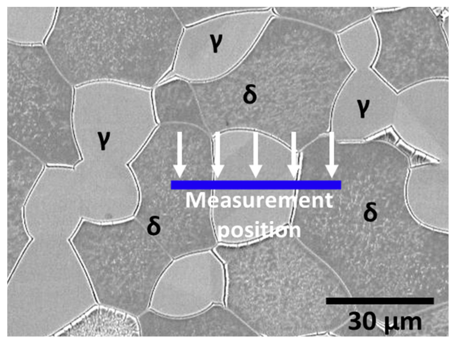
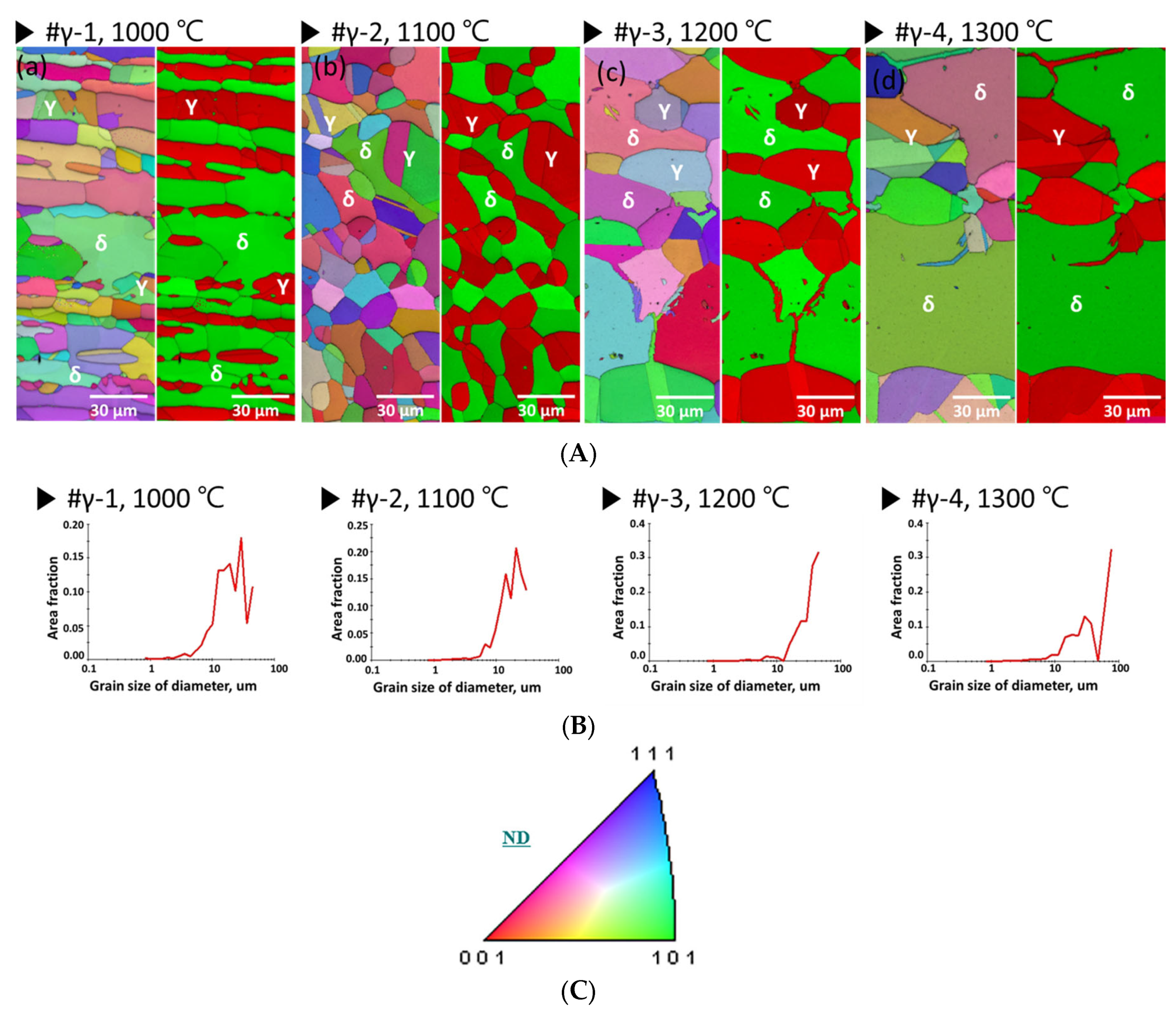
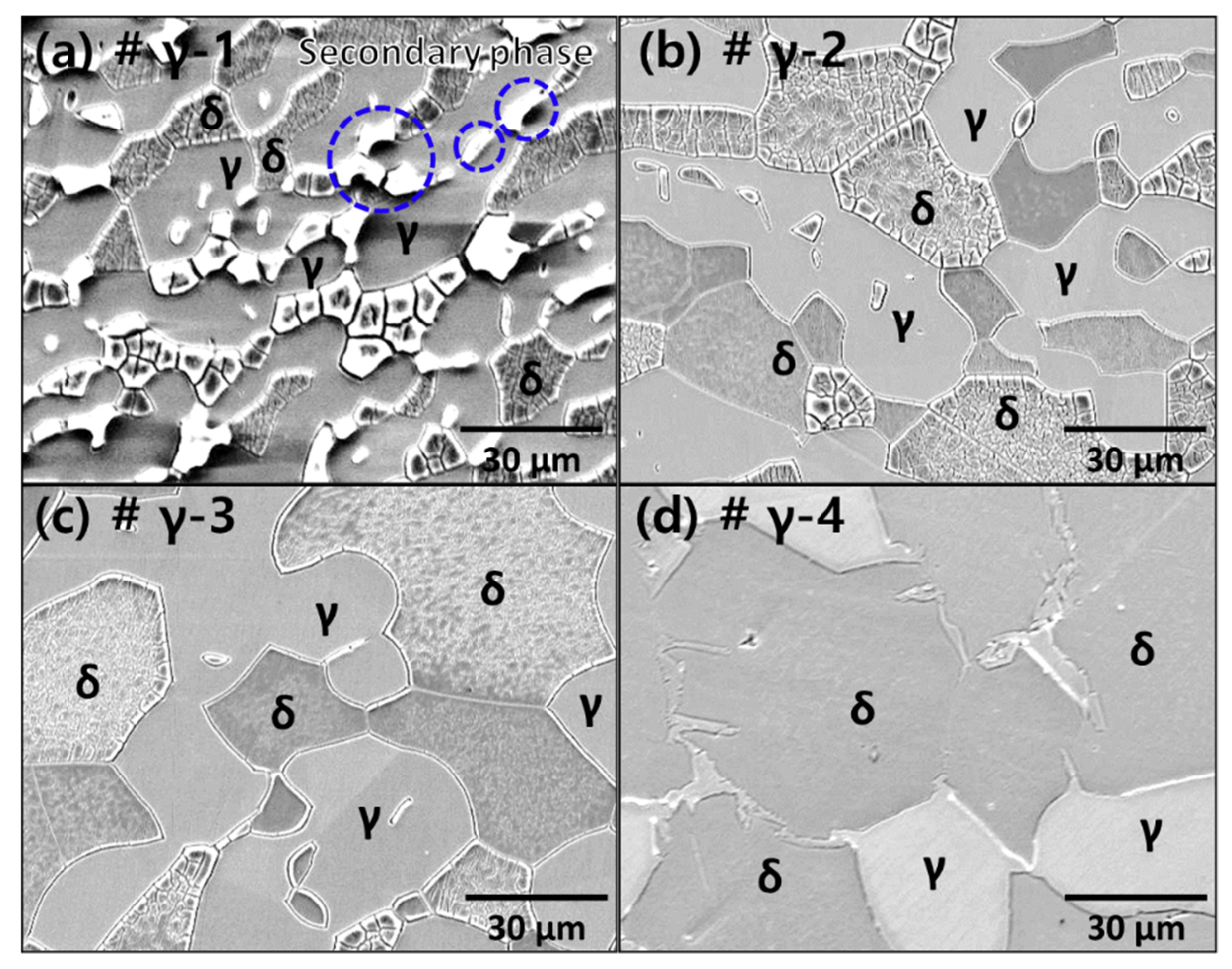
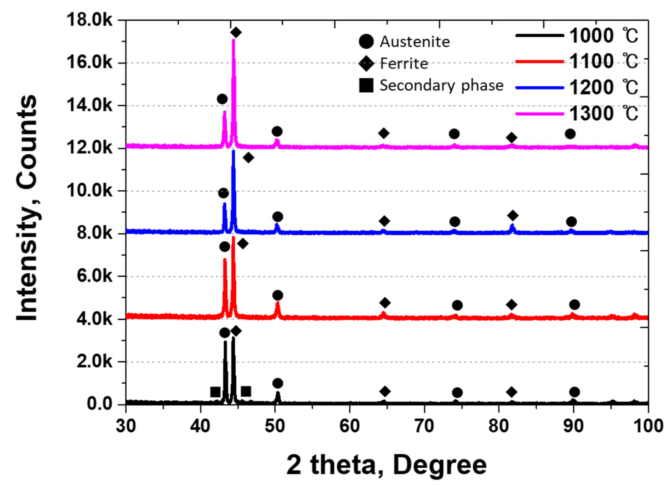
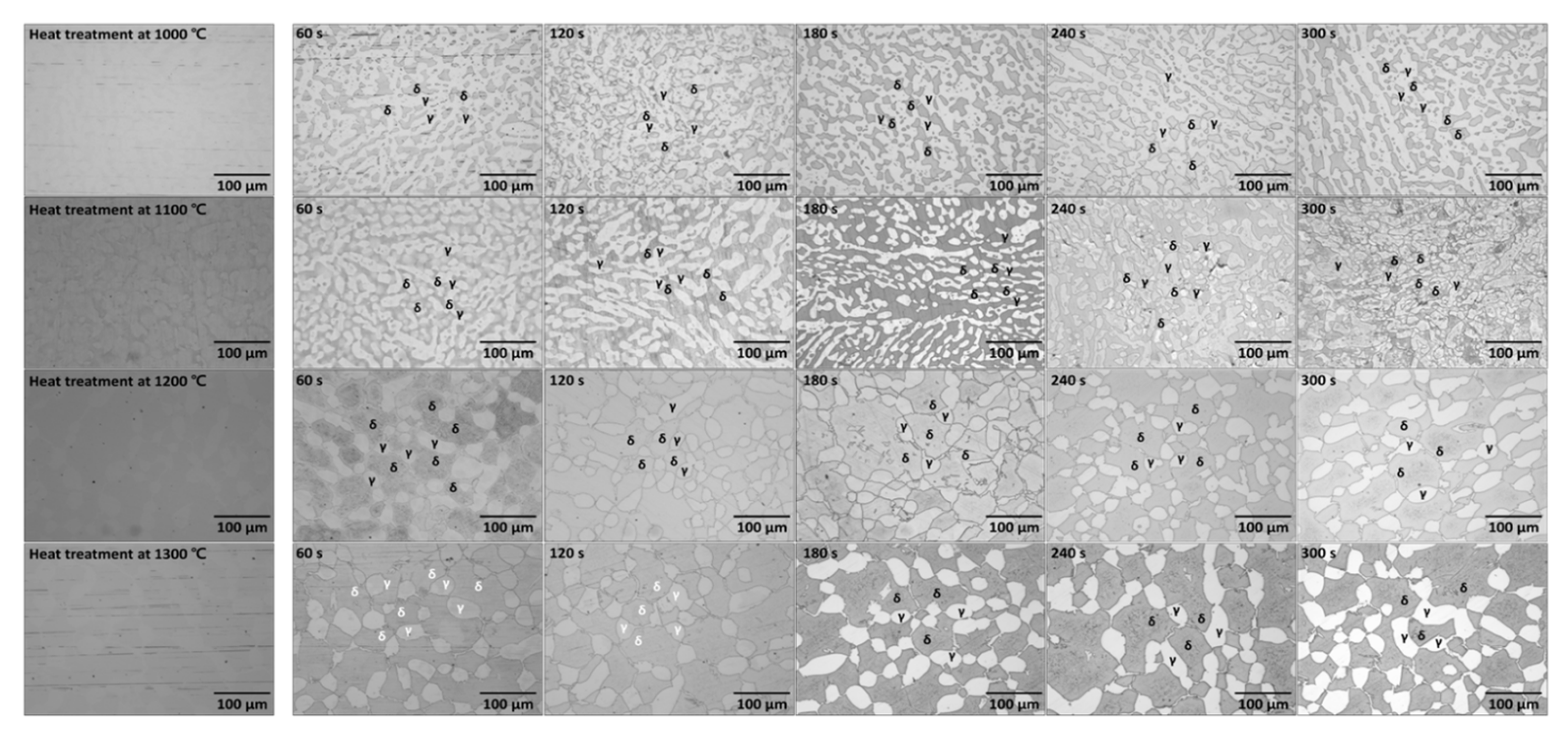
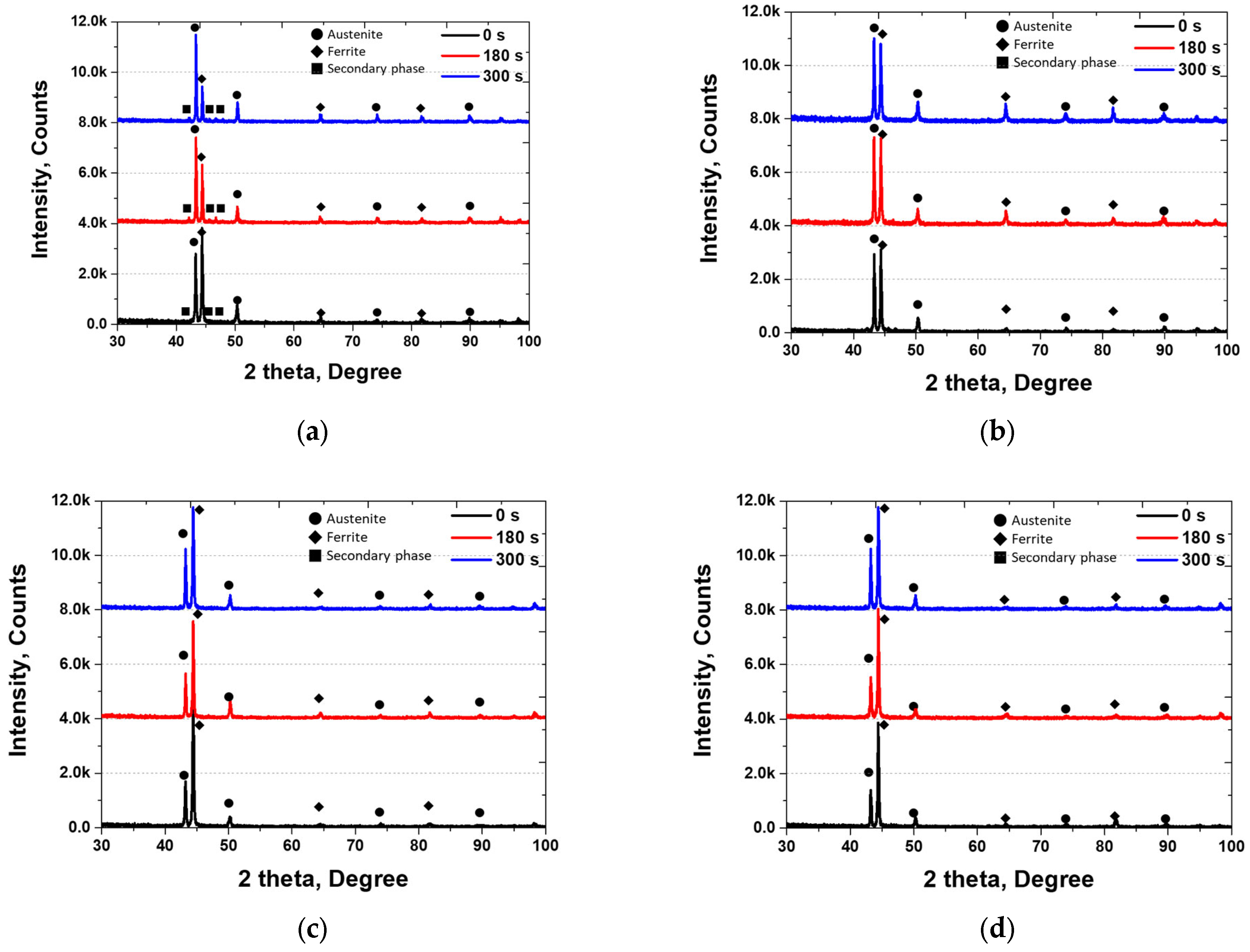
3.1. Microstructure of Ni-Deposited SDSS

The heat-treatment temperature of SDSS is an essential factor in controlling its properties because it affects the fraction of ferrite and austenite [16,19]. The microstructure of the SDSS with respect to the heat-treatment temperature is shown in Figure 3. As the heat-treatment temperature increased, austenite underwent a transformation, and its volume fraction decreased. In contrast, ferrite, which is the base structure, gradually increased from 1100 °C to 1300 °C. At 1000 °C, a secondary phase precipitated, but it was distinguished as ferrite using EBSD analysis.
The crystal size of SDSS was observed as a function of the heat treatment temperature. As the temperature increased from 1100 °C to 1300 °C, an increase in the crystal coarsening of austenite and ferrite was observed. At 1100 °C, austenite and ferrite crystals were observed with dimensions in the 5 to 20 µm range. At 1200 °C, crystals with dimensions in the range of 5 to 40 µm were observed, and at 1300 °C, crystals with dimensions in the range of 5 to 100 µm were observed. This coarsening of crystals can be attributed to the increase in the ferrite fraction (based on microstructure) and the austenite (maximum crystal size growing from 20 µm to 40 µm). Considering the IPF color map, an increase in the heat-treatment temperature resulted in an increase in the crystal orientation of the ferrite from (001) to (111) and (101). The crystal orientation of austenite also transformed from (001) to (111) and (101) with increasing heat-treatment temperatures. Changes in volume fraction and crystal orientation were observed with varying heat-treatment temperatures.
FE-SEM was utilized to scrutinize the microstructure of SDSS in relation to the heat-treatment temperature. Figure 4 and Table 2 present the microstructure and volume fraction of SDSS at varying heat-treatment temperatures. The secondary phase (Blue circles in the figure) precipitated at the grain boundary between austenite and ferrite, and at 1100 °C, it was incorporated into both ferrite and austenite. As the heat-treatment temperature escalated from 1000 °C to 1300 °C, the fraction of austenite diminished from 56% to 28%, while the fraction of ferrite amplified from 26% to 72%. The variation in the fractions of austenite and ferrite signifies the transformation of the secondary phase, which gets incorporated into ferrite with increasing temperature. The phase transfer in SDSS with temperature is attributed to the stabilization of delta ferrite in Fe, primarily due to high levels of alloying elements such as Cr and Mo. Consequently, at temperatures exceeding 1100 °C, an augmentation in the fraction of ferrite occurs while the fraction of austenite decreases.
Because SDSS undergoes changes in volume fractions due to heat treatment, it results in variations in peak intensity and two theta values in XRD analysis. XRD analysis was conducted on the SDSS at different heat-treatment temperatures to determine the presence and state of the phases, and the results are presented in Figure 5 [19,20,36]. As the heat-treatment temperature increased, the intensity of austenite peaks (43° (111), 51° (100), 74° (100)) decreased, the intensity of ferrite peaks (44.5° (111), 64° (100), 81.6° (110)) increased, and the peaks associated with the secondary phase (42.1° (Sigma, (111)), 45.4° (Sigma, (100)), 46.6° (Chi)) disappeared when the heat-treatment temperature was above 1000 °C. Based on the findings from the EBSD, FE-SEM, and XRD patterns, the SDSS was checked for changes in the volume fractions with heat-treatment temperature. This property is a crucial factor in altering the choice of the material, thus necessitating appropriate control depending on the intended application of the material.

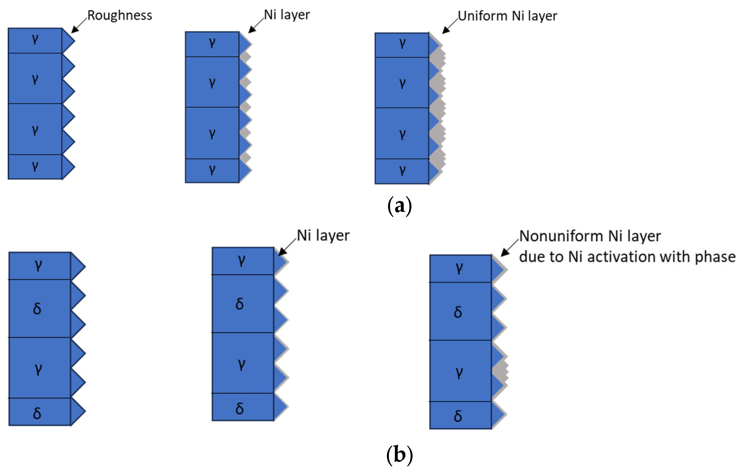
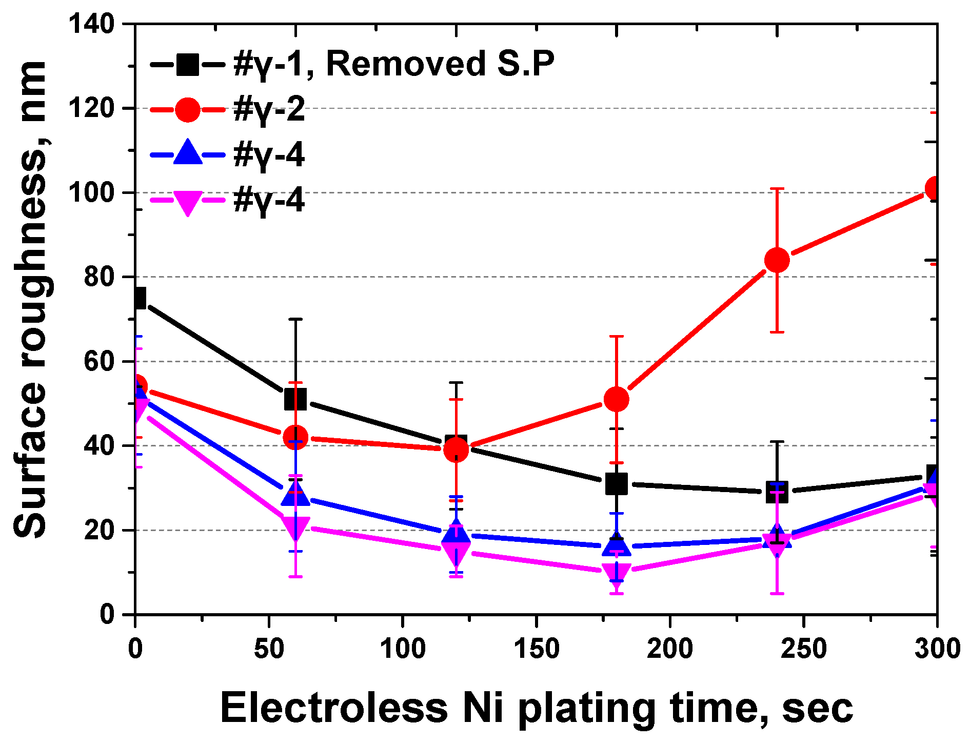
3.2. Electroless Ni Plating Behavior

The SDSS was subjected to electroless Ni plating after heat treatment, and the results are shown in Figure 6. Upon observing the surface images, it became apparent that the difference in reactivity between austenite and ferrite made it easier to distinguish them after electroless Ni plating. The electroless Ni plating behavior of Stainless Steel 304 (γ, single phase) and SDSS is illustrated in Ni plating behavior in Figure 7 [27,29]. During the electroless Ni plating process, there were differences in behavior owing to variations in the reactivity between the single-phase stainless steel and DSS. Electroless Ni plating initially reduced the surface roughness at the grain boundaries for single-phase materials. After plating, a uniform Ni layer was formed, reducing the surface defects caused by grain boundaries. In contrast, duplex materials exhibit preferential reactions at the grain boundaries of more reactive phases. The difference in reactivity between austenite and ferrite makes it easier to distinguish between these phases. The variations in the crystal structures of austenite and ferrite in electroless Ni plating are attributed to differences in Ni reactivity. The secondary phase was indistinguishable after plating. During electroless Ni plating, the secondary phase facilitated Ni diffusion owing to the differences in surface roughness. After plating, the secondary phase resembled ferrite and austenite.
The effect of the volume fractions on the electroless Ni plating of SDSS was investigated. Secondary phases and ferrites were identified as the factors that decreased the Ni plating rate. Secondary phases appeared to reduce the plating rate owing to the reduced surface smoothness and reactivity, whereas ferrite exhibited differences in reactivity owing to lattice mismatches. When the austenite fraction was at 50%, a distinct boundary between phases was observed at 180 s, but this boundary deteriorated at 300 s. The electroless Ni plating primarily reacted with austenite, and as the Ni layer thickness increased, the boundary between ferrite and austenite deteriorated.
After the heat treatment and subsequent plating, the surface of the SDSS was analyzed using XRD, and the results are presented in Figure 8. As the plating time increased, the intensity of the peak associated with the face-centered cubic (FCC) structure increased, whereas that of the body-centered cubic (BCC) structure decreased [29]. The peak intensity varied depending on the heat treatment temperature, and this difference was the same as that of the volume fraction. Because austenite and Ni share the same peak, an increase in the thickness of the Ni plating layer results in an increase in the intensity of austenite. As the electroless Ni plating time increased, the austenite peak intensity increased in all heat-treated materials.
The surface roughness was measured using AFM; the results are shown in Figure 9 and Table 3. Secondary phases not removed during surface polishing contributed to increased surface roughness. Distinct differences in the surface roughness were observed in areas with and without secondary phases. As the plating time increased, the surface roughness initially decreased; however, after 120 s, it began to increase. This variation in surface roughness appears to be associated with differences in Ni plating reactivity owing to the reaction kinetics of FCC and BCC [29,30]. Austenite has an FCC structure, which is the same as the crystal structure (lattice constant) of Ni, leading to a rapid reaction. In contrast, ferrite has a BCC structure that differs from that of Ni (different lattice constants), resulting in slower reactivity [44,45,46].
The initial decrease in roughness was ascribed to a reduction in surface indentation, while the increase in roughness was influenced by the differences in reactivity between the austenite and ferrite phases. In instances where secondary phases were present, the slower decrease in roughness was attributed to the substantial differences in reactivity and roughness between these secondary phases and austenite. Conversely, in the absence of secondary phases, the plating rate is primarily determined using the reactivity between austenite and ferrite. An increase in the ferrite fraction resulted in a decreased plating rate due to the lower reactivity of ferrite. Therefore, the phase fraction of SDSS significantly impacted the electroless Ni plating process.

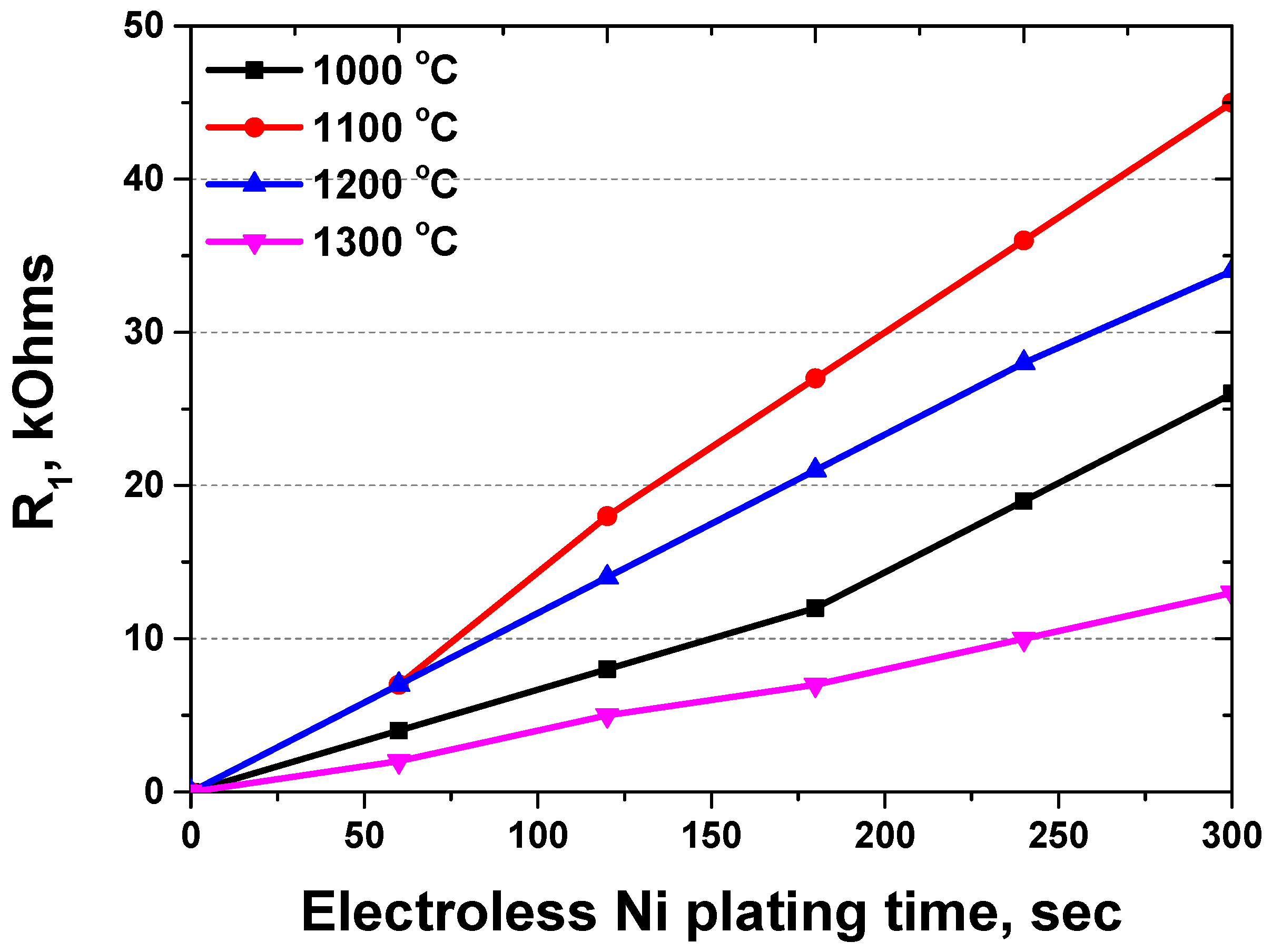
3.3. Electrochemical Behavior

After electroless Ni plating, the surface condition of SDSS was assessed using EIS [33,42,43]. The changes in resistance as a function of frequency were measured to evaluate the surface state, and the results are presented in Figure 10 and Table 4. The Bode plot shows the variation in degree and ohms with frequency owing to the resistance change.
Analysis of SDSS subjected to solution annealing and electroless Ni plating revealed three distinct stages of resistance: solution resistance (RS), plating layer resistance (R1), and passive layer resistance (R2). The solution resistance remained constant throughout the experiment. The plating layer resistance increased with plating time, causing the resistance in solution-annealed SDSS to rise to 45 kOhms in EIS. When the plating time was 0 s, R1 was not observed because no layers were formed.
The resistance of the plating layer varied depending on the volume fraction. The main factor affecting the Ni plating was the reactivity of austenite. An increase in the austenite fraction increased the resistance of the Ni plating layer. However, the secondary phase acts as an exception, diminishing the plating capability because of the high roughness and segregation of the chemical composition.
We investigated the variation in Ni plating thickness as a function of the phase fraction using EIS, and the results are presented in Figure 11 [33,42,43]. Due to the reactivity differences between Ni and the phases, the plating thickness varied depending on the volume fraction.
The presence of secondary phases appeared to reduce plating thickness, which was checked to decrease the resistance of the Ni layer. Upon conducting solution annealing, it was noticed that the Ni layer exhibited the highest thickness when the volume portion of austenite reached 50%, and no secondary phase was present. As the volume fraction of ferrite increased, the Ni layer thickness decreased, and with increasing plating time, the difference in the Ni layer resistance also increased.

4. Discussion

We analyzed SDSS after heat treatment and subsequent electroless Ni plating. The SDSS underwent secondary phase precipitation, solution annealing, and ferritization following heat treatment. Changes in the volume fractions and morphological transformations of austenite were observed with respect to the heat-treatment temperature [16,19].
At 1000 °C heat treatment, SDSS promoted the growth of austenite, leading to secondary phase precipitation at the boundary of ferrite [36]. Heat treatment at 1100 °C equalized the volume fractions of austenite and ferrite in SDSS, whereas subsequent treatments at 1200 °C and 1300 °C promoted ferrite growth to 73%. During these Ni plating processes, fine austenite transforms into ferrite, depleting austenite [23,25,27].
The volume fractions during the electroless Ni plating significantly influenced the SDSS. Plating led to a reduction in surface roughness. The secondary phase, post-plating, bore a resemblance to ferrite. The XRD analysis confirmed the intensity of the secondary phase and a decrease in the intensity of ferrite. The secondary phase appeared ferrite-like but was located beneath the Ni plating layer. The fractions of ferrite and austenite influenced the Ni plating capability. An increase in the ferrite fraction from 50% to 73% reduced the Ni plating stabilization range from 120 s to 180 s. The phase fraction between austenite and ferrite impacts the plating rate due to differences in their lattice structures.
The ferrite and austenite fractions also influenced the Ni plating performance. An increase in the ferrite fraction from 50% to 73% reduced the resistance (R1) of the plating layer from 45 kOhms to 13 kOhms at 300 s. Subsequently, the resistance of the passivation layer (R2) remained constant. The resistance of the plating layer increased proportionally with electroless Ni plating time, and the volume fraction was a limiting factor depending on the desired outcome [33,42,43].
This study confirms that electroless Ni-plated SDSS can achieve a uniform Ni layer, depending on the electroless Ni plating time. The uniform Ni-plated layer on SDSS exhibited excellent electroconductivity, making it suitable for both the anode and cathode in Li-ion batteries. Furthermore, the outstanding strength and corrosion resistance of SDSS makes it a suitable material for Li-ion battery casings. Considering these results, Ni-plated SDSS can be considered for use as a casing material in Li-ion batteries, contributing to integrating both the cathode and anode.

5. Conclusions

The phase fraction was regulated to utilize SDSS in Li-ion batteries, and the material characteristics were analyzed with respect to electroless Ni plating time and heat-treatment temperature. The results are as follows:
SDSS displays variations in the proportions of austenite and ferrite phases depending on the heat treatment temperature. As the temperature increases from 1000 °C to 1300 °C, the volume fraction of the secondary phase disappears, the volume fraction of ferrite increases and that of austenite decreases. These changes in material properties with heat-treatment temperature are controllable, making SDSS a suitable candidate for battery casing applications due to its high corrosion resistance and strength.
Both the secondary phases and ferrite in SDSS acted as elements that reduced the capability of electroless Ni plating. The secondary phase was confirmed to be a factor that reduces the resistance of the plating layer. An increase in the fraction of ferrite reduces the thickness of the plated layer. When the fraction of ferrite increases from 50% to 73%, the resistance of the plated layer decreases from 45 kOhms to 13 kOhms in EIS measurements. To enhance plating capability and corrosion resistance, it is advisable to perform heat treatment on SDSS at 1100 °C.
SDSS, which has undergone heat treatment at 1100 °C, exhibits outstanding strength and corrosion resistance, making it highly suitable for electroless Ni plating. During manufacturing, SDSS heat-treated at 1100 °C provides an advantage by facilitating electroless Ni plating without requiring additional heat treatment. Thus, SDSS is a promising choice for battery casing applications as it can be employed as a high-performance casing material without additional heat treatment.
The use of Ni-plating may be effectively leveraged to enhance the performance of conventional materials like SDSS in many applications, including cathodes, anodes, and casings. The current body of research on battery materials indicates that the use of Ni-plating technology on SDSS has the potential to serve as a fundamental basis for the advancement of battery casing materials in the future.

Author Contributions

Conceptualization, B.-H.S. and S.-H.K.; methodology, D.-I.K.; formal analysis, B.-H.S.; investigation, B.-H.S. and D.K.; resources, S.-H.K.; writing, original. draft preparation, B.-H.S.; writing—review and editing, D.-I.K. and W.L.; All authors have read and agreed to the published version of the manuscript.

Funding

This research was funded by a 2-Year Research Grant from Pusan National University.

Institutional Review Board Statement

Not applicable.

Informed Consent Statement

Not applicable.

Data Availability Statement

The data supporting the findings of this study are available from the corresponding author upon request.

Conflicts of Interest

The authors declare no conflict of interest.

References

  1. Rahman, A.; Lin, X. Li-Ion Battery Individual Electrode State of Charge and Degradation Monitoring Using Battery Casing through Auto Curve Matching for Standard CCCV Charging Profile. Appl. Energy 2022, 321, 119367. [Google Scholar] [CrossRef]
  2. Tudoroiu, R.-E.; Zaheeruddin, M.; Tudoroiu, N.; Radu, S.M.; Chammas, H. Investigations of Different Approaches for Controlling the Speed of an Electric Motor with Nonlinear Dynamics Powered by a Li-Ion Battery-Case Study. In Electric Vehicles—Design, Modelling and Simulation; Intechopen: London, UK, 2023. [Google Scholar]
  3. Chang, W.-S.; Park, C.-M.; Kim, J.-H.; Kim, Y.-U.; Jeong, G.; Sohn, H.-J. Quartz (SiO2): A New Energy Storage Anode Material for Li-Ion Batteries. Energy Env. Sci. 2012, 5, 6895–6899. [Google Scholar] [CrossRef]
  4. Mayyas, A.; Steward, D.; Mann, M. The Case for Recycling: Overview and Challenges in the Material Supply Chain for Automotive Li-Ion Batteries. Sustain. Mater. Technol. 2019, 19, e00087. [Google Scholar] [CrossRef]
  5. Petit, M.; Prada, E.; Sauvant-Moynot, V. Development of an Empirical Aging Model for Li-Ion Batteries and Application to Assess the Impact of Vehicle-to-Grid Strategies on Battery Lifetime. Appl. Energy 2016, 172, 398–407. [Google Scholar] [CrossRef]
  6. Tobolsky, A.; Eyring, H. Mechanical Properties of Polymeric Materials. J. Chem. Phys. 1943, 11, 125–134. [Google Scholar] [CrossRef]
  7. Tjong, S.C. Structural and Mechanical Properties of Polymer Nanocomposites. Mater. Sci. Eng. R Rep. 2006, 53, 73–197. [Google Scholar] [CrossRef]
  8. Jacob, G.C.; Starbuck, J.M.; Fellers, J.F.; Simunovic, S.; Boeman, R.G. Strain Rate Effects on the Mechanical Properties of Polymer Composite Materials. J. Appl. Polym. Sci. 2004, 94, 296–301. [Google Scholar] [CrossRef]
  9. Rana, R.S.; Purohit, R.; Das, S. Reviews on the Influences of Alloying Elements on the Microstructure and Mechanical Properties of Aluminum Alloys and Aluminum Alloy Composites. Int. J. Sci. Res. Publ. 2012, 2, 1–7. [Google Scholar]
  10. Prasad, D.S.; Shoba, C.; Ramanaiah, N. Investigations on Mechanical Properties of Aluminum Hybrid Composites. J. Mater. Res. Technol. 2014, 3, 79–85. [Google Scholar] [CrossRef]
  11. Manesh, H.D.; Taheri, A.K. The Effect of Annealing Treatment on Mechanical Properties of Aluminum Clad Steel Sheet. Mater. Des. 2003, 24, 617–622. [Google Scholar] [CrossRef]
  12. Fredriksson, W.; Edström, K. XPS Study of Duplex Stainless Steel as a Possible Current Collector in a Li-Ion Battery. Electrochim. Acta 2012, 79, 82–94. [Google Scholar] [CrossRef]
  13. Masarapu, C.; Subramanian, V.; Zhu, H.; Wei, B. Long-Cycle Electrochemical Behavior of Multiwall Carbon Nanotubes Synthesized on Stainless Steel in Li Ion Batteries. Adv. Funct. Mater. 2009, 19, 1008–1014. [Google Scholar] [CrossRef]
  14. Pettersson, N.; Pettersson, R.F.A.; Wessman, S. Precipitation of Chromium Nitrides in the Super Duplex Stainless Steel 2507. Metall. Mater. Trans. A 2015, 46, 1062–1072. [Google Scholar] [CrossRef]
  15. Valeriano, L.d.C.; Correa, E.O.; Mariano, N.A.; Robin, A.L.M.; Machado, M.A.G. Influence of the Solution-Treatment Temperature and Short Aging Times on the Electrochemical Corrosion Behaviour of Uns S32520 Super Duplex Stainless Steel. Mater. Res. 2019, 22. [Google Scholar] [CrossRef]
  16. Nilsson, J.-O. Super Duplex Stainless Steels. Mater. Sci. Technol. 1992, 8, 685–700. [Google Scholar] [CrossRef]
  17. Topolska, S.; Łabanowski, J. Effect of Microstructure on Impact Toughness of Duplex and Superduplex Stainless Steels. J. Achiev. Mater. Manuf. Eng. 2009, 36, 142–149. [Google Scholar]
  18. Tehovnik, F.; Arzensek, B.; Arh, B.; Skobir, D.; Pirnar, B.; Zuzek, B. Microstructure Evolution in SAF 2507 Super Duplex Stainless Steel. Mater. Technol. 2011, 45, 339–345. [Google Scholar]
  19. Nilsson, J.O.; Wilson, A. Influence of Isothermal Phase Transformations on Toughness and Pitting Corrosion of Super Duplex Stainless Steel SAF 2507. Mater. Sci. Technol. 1993, 9, 545–554. [Google Scholar] [CrossRef]
  20. Paulraj, P.; Garg, R. Effect of Intermetallic Phases on Corrosion Behavior and Mechanical Properties of Duplex Stainless Steel and Super-Duplex Stainless Steel. Adv. Sci. Technol. Res. J. 2015, 9, 87–105. [Google Scholar]
  21. Valiente Bermejo, M.A.; Thalavai Pandian, K.; Axelsson, B.; Harati, E.; Kisielewicz, A.; Karlsson, L. Microstructure of Laser Metal Deposited Duplex Stainless Steel: Influence of Shielding Gas and Heat Treatment. Weld. World 2021, 65, 525–541. [Google Scholar] [CrossRef]
  22. Trinh, L.N.; Lee, D. The Characteristics of Laser Welding of a Thin Aluminum Tab and Steel Battery Case for Lithium-Ion Battery. Metals 2020, 10, 842. [Google Scholar] [CrossRef]
  23. Beziou, O.; Hamdi, I.; Boumerzoug, Z.; Brisset, F.; Baudin, T. Effect of Heat Treatment on the Welded Joint of X70 Steel Joined to Duplex Stainless Steel by Gas Tungsten Arc Welding. Int. J. Adv. Manuf. Technol. 2023, 127, 2799–2814. [Google Scholar] [CrossRef]
  24. Elhoud, A.M.; Renton, N.C.; Deans, W.F. Hydrogen Embrittlement of Super Duplex Stainless Steel in Acid Solution. Int. J. Hydrogen Energy 2010, 35, 6455–6464. [Google Scholar] [CrossRef]
  25. Kannan, A.R.; Shanmugam, N.S.; Rajkumar, V.; Vishnukumar, M. Insight into the Microstructural Features and Corrosion Properties of Wire Arc Additive Manufactured Super Duplex Stainless Steel (ER2594). Mater. Lett. 2020, 270, 127680. [Google Scholar] [CrossRef]
  26. Maurya, A.K.; Pandey, C.; Chhibber, R. Effect of Filler Metal Composition on Microstructural and Mechanical Characterization of Dissimilar Welded Joint of Nitronic Steel and Super Duplex Stainless Steel. Arch. Civ. Mech. Eng. 2022, 22, 90. [Google Scholar] [CrossRef]
  27. Lee, H.-B.; Sheu, H.-H.; Jian, J.-S.; Chang, S.-Y.; Yen, C.-H.; Lin, H.-E. Supercritical-CO2 Electroless Nickel Plating Enhanced Anti-Corrosion Properties of Micro-Arc Oxidized AZ31 Magnesium Alloy. Mater. Today Commun. 2022, 33, 104475. [Google Scholar] [CrossRef]
  28. Wang, D.; Li, F.; Liu, M.; Zhang, W.; Yu, X.; Da, W. Effect of Nanodiamond Content in the Plating Solution on the Corrosion Resistance of Nickel–Nanodiamond Composite Coatings Prepared on Annealed 45 Carbon Steel. Coatings 2022, 12, 1558. [Google Scholar] [CrossRef]
  29. Loto, C.A. Electroless Nickel Plating–A Review. Silicon 2016, 8, 177–186. [Google Scholar] [CrossRef]
  30. Choi, Y.; Kim, D.; Son, K.; Lee, S.; Chung, W. Effect of Added Dispersants on Diamond Particles in Ni-Diamond Composites Fabricated with Electrodeposition. Met. Mater. Int. 2015, 21, 977–984. [Google Scholar] [CrossRef]
  31. Di Bari, G.A. Nickel Plating. Met. Finish. 1994, 9, 270–276. [Google Scholar]
  32. Baudrand, D.W. Electroless Nickel Plating; Cambridge Scientific Abstracts: Bethesda, ML, USA, 1994. [Google Scholar]
  33. Rybalka, K.V.; Beketaeva, L.A.; Davydov, A.D. Electrochemical Behavior of Stainless Steel in Aerated NaCl Solutions by Electrochemical Impedance and Rotating Disk Electrode Methods. Russ. J. Electrochem. 2006, 42, 370–374. [Google Scholar] [CrossRef]
  34. Baghdadchi, A.; Hosseini, V.A.; Valiente Bermejo, M.A.; Axelsson, B.; Harati, E.; Högström, M.; Karlsson, L. Wire Laser Metal Deposition of 22% Cr Duplex Stainless Steel: As-Deposited and Heat-Treated Microstructure and Mechanical Properties. J. Mater. Sci. 2022, 57, 9556–9575. [Google Scholar] [CrossRef]
  35. Ha, H.-Y.; Jang, M.-H.; Lee, T.-H.; Moon, J. Interpretation of the Relation between Ferrite Fraction and Pitting Corrosion Resistance of Commercial 2205 Duplex Stainless Steel. Corros. Sci. 2014, 89, 154–162. [Google Scholar] [CrossRef]
  36. Martins, M.; Casteletti, L.C. Sigma Phase Morphologies in Cast and Aged Super Duplex Stainless Steel. Mater. Charact. 2009, 60, 792–795. [Google Scholar] [CrossRef]
  37. Sung, C.; Shin, B.-H.; Chung, W. Effect of Solution Annealing on Austenite Morphology and Pitting Corrosion of Super Duplex Stainless Steel UNS S 32750. Int. J. Electrochem. Sci. 2021, 16, 210813. [Google Scholar] [CrossRef]
  38. Sung, C.; Kim, K.; Chung, W.; Shin, B.-H. Electrochemical Properties of UNS S 32750 and UNS S 32760 Annealed Super Duplex Stainless Steels. Int. J. Electrochem. Sci. 2022, 17, 220526. [Google Scholar] [CrossRef]
  39. Kim, D.; Kim, K.; Chung, W.; Shin, B.-H. Effect of the Plating Time on Nickel Electroless Coating Properties Deposited on the Super Duplex Stainless Steel UNS S 32750. Int. J. Electrochem. Sci. 2022, 17, 220630. [Google Scholar] [CrossRef]
  40. Goksu, E.I.; Vanegas, J.M.; Blanchette, C.D.; Lin, W.-C.; Longo, M.L. AFM for Structure and Dynamics of Biomembranes. Biochim. Et Biophys. Acta (BBA) Biomembr. 2009, 1788, 254–266. [Google Scholar] [CrossRef]
  41. Bogdan, D.; Grosu, I.-G.; Filip, C. How Thick, Uniform and Smooth Are the Polydopamine Coating Layers Obtained under Different Oxidation Conditions? An in-Depth AFM Study. Appl. Surf. Sci. 2022, 597, 153680. [Google Scholar] [CrossRef]
  42. Guerrini, E.; Cristiani, P.; Grattieri, M.; Santoro, C.; Li, B.; Trasatti, S. Electrochemical Behavior of Stainless Steel Anodes in Membraneless Microbial Fuel Cells. J. Electrochem. Soc. 2013, 161, H62. [Google Scholar] [CrossRef]
  43. Makhdoom, M.A.; Ahmad, A.; Kamran, M.; Abid, K.; Haider, W. Microstructural and Electrochemical Behavior of 2205 Duplex Stainless Steel Weldments. Surf. Interfaces 2017, 9, 189–195. [Google Scholar] [CrossRef]
  44. Korhonen, T.; Puska, M.J.; Nieminen, R.M. Vacancy-Formation Energies for FCC and Bcc Transition Metals. Phys. Rev. B 1995, 51, 9526. [Google Scholar] [CrossRef]
  45. Ghosh, S.K.; Grover, A.K.; Dey, G.K.; Totlani, M.K. Nanocrystalline Ni–Cu Alloy Plating by Pulse Electrolysis. Surf. Coat. Technol. 2000, 126, 48–63. [Google Scholar] [CrossRef]
  46. Rehman, A.U.; Lee, S.H. Review of the Potential of the Ni/Cu Plating Technique for Crystalline Silicon Solar Cells. Materials 2014, 7, 1318–1341. [Google Scholar] [CrossRef]
Figure 1. Heat treatment condition for advanced ferrite fraction on SDSS SAF 2507 (a) Schematic diagram for heat treatment of SDSS, (b) FE-SEM image of #a and #b, and (c) volume fraction with the heat-treatment condition.
Coatings 13 01807 g001
Figure 2. Schematic diagram to calculate the surface roughness with the electroless Ni plating time of the SDSS, SAF 2507.
Coatings 13 01807 g002
Figure 3. EBSD grain map showing the austenite and ferrite of SDSS SAF 2507 after heat-treatment temperatures (A) Inverse pole figure image quality (IPF-IQ) and Phase-IQ (a) Image after heat treatment at 1000 °C (b) Image after heat treatment at 1100 °C, (c) Image after heat treatment at 1200 °C, (d) Image after heat treatment at 1300 °C, (B) Grain size of diameter, (C) Stereo-graphic triangle of IPF color map.
Coatings 13 01807 g003
Figure 4. FE-SEM image of SDSS with heat-treatment temperature after electro-etching at 5 V in 5 wt% KOH of (a) 1000 °C, (b) 1100 °C, (c) 1200 °C, and (d) 1300 °C.
Coatings 13 01807 g004
Figure 5. XRD pattern of SDSS with heat treatment temperature.
Coatings 13 01807 g005
Figure 6. Surface image of SDSS with Ni plating time from 0 s to 300 s after heat treatment.
Coatings 13 01807 g006
Figure 7. Schematic diagram of electroless Ni plating on metal (a) Single phase stainless steel and (b) SDSS.
Coatings 13 01807 g007
Figure 8. XRD pattern of SDSS with Ni plating time after heat treatment at (a) 1000 °C, (b) 1100 °C, (c) 1200 °C, and (d) 1300 °C.
Coatings 13 01807 g008
Figure 9. Surface roughness of SDSS with electroless Ni plating time after heat treatment to atomic force microscope.
Coatings 13 01807 g009
Figure 10. EIS results of SDSS with Ni plating time after heat treatment (a′) Frequency vs. Angle of phase, Bode plot, (a″) Frequency vs. Resistance, Bede plot (b′) Nyquist plot of Rs, (b″) Nyquist plot of R1, (b‴) Nyquist plot of R2, (b⁗) EIS circuit, (c) Nyquist plot with electroless Ni plating condition.
Coatings 13 01807 g010
Figure 11. Ni layer resistance of SDSS with electroless Ni plating time.
Coatings 13 01807 g011
Table 1. Chemical composition of SDSS SAF 2507.
CNMnNiCrMoFe
Total0.010.270.86.825.03.8Bal
Austenite0.010.510.95.523.33.2Bal
Ferrite0.010.050.87.926.64.4Bal
Table 2. Volume fraction and properties of SDSS with heat-treatment temperature.
ConditionPropertiesVolume Fraction
AusteniteFerriteSecondary Phase
(a) # γ-1, 1000 °CSecondary phase56 ± 1%26 ± 1%18 ± 1%
(b) # γ-2, 1100 °CSolution annealing50 ± 1%50 ± 1%0%
(c) # γ-3, 1200 °COver ferrite 60%39 ± 2%61 ± 2%0%
(d) # γ-4, 1300 °COver ferrite 70%28 ± 3%72 ± 3%0%
Table 3. Surface roughness of SDSS with electroless Ni plating time after heat treatment to atomic force microscope.
Ra, nm0 s60 s120 s180 s240 s300 s
# γ-11675 ± 2211751 ± 2191540 ± 2151431 ± 2131529 ± 2121633 ± 218
# γ-1 (Removed S.P)73 ± 2149 ± 1946 ± 1536 ± 1331 ± 1232 ± 18
# γ-254 ± 1242 ± 1339 ± 1251 ± 1584 ± 17101 ± 18
# γ-352 ± 1428 ± 1319 ± 916 ± 818 ± 1331 ± 15
# γ-449 ± 1421 ± 1215 ± 610 ± 517 ± 1229 ± 13
Table 4. EIS values of SDSS with Ni plating time after heat treatment.
ConditionRsCPE1R1 (kOhms)CPE2R2 (kOhms)
C1N1C2N2
# γ-10 s0.10006.5 × 10−50.5326
60 s0.10.6 × 10−40.646.5 × 10−50.5326
120 s0.11.2 × 10−40.686.5 × 10−50.5326
180 s0.12.0 × 10−40.6126.5 × 10−50.5326
240 s0.13.1 × 10−40.6196.5 × 10−50.5326
300 s0.14.3 × 10−40.6266.5 × 10−50.5326
# γ-20 s0.10006.8 × 10−50.5340
60 s0.11.1 × 10−40.676.8 × 10−50.5340
120 s0.13.0 × 10−40.6186.8 × 10−50.5340
180 s0.14.5 × 10−40.6276.8 × 10−50.5340
240 s0.16.0 × 10−40.6366.8 × 10−50.5340
300 s0.17.5 × 10−40.6456.8 × 10−50.5340
# γ-30 s0.10006.7 × 10−50.5335
60 s0.11.1 × 10−40.676.7 × 10−50.5335
120 s0.12.3 × 10−40.6146.7 × 10−50.5335
180 s0.13.5 × 10−40.6216.7 × 10−50.5335
240 s0.14.7 × 10−40.6286.7 × 10−50.5335
300 s0.15.7 × 10−40.6346.7 × 10−50.5335
# γ-40 s0.10006.6 × 10−50.5325
60 s0.10.4 × 10−40.626.6 × 10−50.5325
120 s0.10.8 × 10−40.656.6 × 10−50.5325
180 s0.11.2 × 10−40.676.6 × 10−50.5325
240 s0.11.6 × 10−40.6106.6 × 10−50.5325
300 s0.12.2 × 10−40.6136.6 × 10−50.5325
Disclaimer/Publisher’s Note: The statements, opinions and data contained in all publications are solely those of the individual author(s) and contributor(s) and not of MDPI and/or the editor(s). MDPI and/or the editor(s) disclaim responsibility for any injury to people or property resulting from any ideas, methods, instructions or products referred to in the content.

