Article

A Comparative Thermodynamic Study of AlF3, ScF3, Al0.5Sc0.5F3, and In0.5Sc0.5F3 for Optical Coatings: A Computational Study

by
Adel Bandar Alruqi
1,* and
Nicholas O. Ongwen
2,3
1
Department of Physics, Faculty of Science, King Abdulaziz University, Jeddah 21589, Saudi Arabia
2
Department of Physics and Materials Science, Maseno University, Maseno 40137, Kenya
3
Faculty of Biological and Physical Sciences, Tom Mboya University, Homa-Bay 40300, Kenya
*
Author to whom correspondence should be addressed.
Coatings 2023, 13(11), 1840; https://doi.org/10.3390/coatings13111840
Submission received: 17 September 2023 / Revised: 12 October 2023 / Accepted: 25 October 2023 / Published: 27 October 2023

Abstract

:
Optical coatings are thin layers of materials applied to optical components in order to modify the transmission, reflection, or polarization properties of light. The common materials used for optical coatings include magnesium fluoride ( M g F 2 ), scandium trifluoride ( S c F 3 ), and aluminum trifluoride ( A l F 3 ), owing to their desirable optical properties, spectral range, and compatibility with substrates. However, each of these materials has its own drawbacks. For instance, A l F 3 has been found to exhibit limited resistance to attack by chemicals, as well as poor thermal stability, while M g F 2 has low durability, as well as being hygroscopic. In this study, we undertook ab initio calculations in order to compare the thermal properties of A l F 3 , S c F 3 , A l 0.5 S c 0.5 F 3 , and I n 0.5 S c 0.5 F 3 in order to obtain the best material for optical coatings. M g F 2 was also included in the study as a reference. The calculations used PBE pseudopotentials and the extended generalized gradient approximation within the quantum espresso algorithm. The study demonstrated that the computed results agree with the information found in the literature. S c F 3 exhibited a negative coefficient of thermal expansion, unlike the other four. Moreover, A l F 3 was found to be the best candidate for optical coatings that are used in high-power laser systems with high thermal dissipation, due to its superior thermal expansion coefficient as well as its better response to thermal stress. The large variation between the c p and c v of S c F 3 is not desirable. Moreover, due to its negative thermal expansion coefficient, S c F 3 is not thermally stable. The highest thermal stability was exhibited by I n 0.5 S c 0.5 F 3 . Since A l 0.5 S c 0.5 F 3 and I n 0.5 S c 0.5 F 3 have been modeled in this study for the first time, experimental determination of their crystal structures needs to be investigated.

1. Introduction

An optical coating (also known as a thin-film coating or an optical thin film) refers to the process of applying thin layers of specialized materials onto the surface of optical components such as lenses, mirrors, prisms, and filters [1]. These coatings are designed to manipulate the behavior of light that interacts with the coated surface. Optical coatings are used to enhance the performance of optical systems by controlling properties such as reflection, transmission, absorption, and polarization of light [2]. The main aims of optical coatings include anti-reflection (to reduce unwanted reflections at the interfaces between different optical elements or between an optical element and the surrounding medium); bandpass and notch filtration (to selectively transmit or block certain wavelengths of light); beam splitting (to divide incoming light into two or more separate beams with specific intensity ratios); and polarization control (to manipulate the polarization state of light, allowing specific polarization components to pass through or to be reflected). The selection of materials and the thickness of the optical coatings are carefully controlled during the manufacturing process so as to obtain the coveted optical properties. The goal is to achieve high optical performance while minimizing unwanted side effects, such as light scattering and thermal effects [3].
Optical coatings play a crucial role in a wide range of applications, including cameras, telescopes, microscopes, laser systems, and optical communication devices [1]. The desirable properties of materials used for optical coatings depend on the specific application and the intended purpose of the coating. However, there are several key properties that are generally sought after in the materials for optical coatings, which include optical transparency, refractive index, bandgap, stability (mechanical, thermal, and optical), and adhesion. In addition, the coatings should be environmentally friendly [4]. Materials for optical coatings usually have wide bandgaps, with that of magnesium fluoride ( M g F 2 ) being 13.0 eV [5]. A previous study by Pankratova, Purans, and Pankratov [6] found the bandgap of scandium trifluoride ( S c F 3 ) to be 11.02 eV. The stability of optical coatings under long-term exposure to optical radiation is a critical consideration, especially in applications where the coatings are exposed to intense light sources or prolonged periods of irradiation. The stability of a coating is influenced by various factors, including the coating material, design, deposition technique, and the specific environment in which it is used. Point defects in crystals can give rise to luminescence, which is the emission of light or photons by a material. The luminescence can be due to various types of point defects (vacancies, interstitials, or impurities), each with its own mechanism of light emission [5,6].
The common materials that are currently being utilized for optical coatings include metal oxides such as titanium IV oxide and tantalum oxide; metal fluorides such as M g F 2 and aluminum trifluoride ( A l F 3 ); dielectric materials such as silicon IV oxide and silicon nitride; and some specialized compounds such as S c F 3 . While M g F 2 has several advantages, such as high transparency in the ultraviolet and infrared regions of the electromagnetic spectrum and good resistance to thermal and mechanical stress, it also has some disadvantages as a coating material, which include poor durability, and being hygroscopic [1,7,8,9]. The materials mentioned above have their unique properties that are ideal for optical coatings. S c F 3 for instance, combines a high refractive index, transparency, and compatibility with other optical materials, which makes it a valuable component in optical coatings [10]. A l F 3 , on the other hand, has the combination of good optical properties, spectral range, and compatibility with other materials, which makes it a valuable component in optical coatings, particularly in applications where anti-reflection properties are essential, such as lenses, prisms, and optical filters [11].
However, each of the mentioned materials has its own drawbacks. For instance, it is worth noting that while S c F 3 possesses the desirable properties for optical coating application, scandium itself is a relatively rare and expensive element, which can limit the widespread use in some of these applications due to cost constraints [12]. A l F 3 , on the other hand, is characterized by low hardness that makes the coatings more susceptible to scratching and wear in abrasive environments, limited durability due to softness and lower mechanical stability, limited resistance to attack by chemicals, and poor thermal stability. Moreover, A l F 3 is hygroscopic, implying that it can absorb moisture from the atmosphere [13]. This might eventually cause the coating’s optical properties to change, especially in humid environments. Achieving the right balance of these properties is therefore crucial for designing effective optical coatings tailored to specific applications, ensuring improved performance and versatility in a wide range of optical systems [1].
Thermal properties are desirable and important considerations for optical coating materials. The thermal properties of the coating material can impact its performance, stability, and durability, particularly in applications where the coatings may be exposed to varying temperatures or high-power light sources [14]. The key thermal properties of coating materials include thermal expansion coefficient, thermal conductivity, thermal stability, and thermal shock resistance. The thermal expansion coefficient represents how much a material expands or contracts with changes in temperature. When an optical coating is applied to a substrate with a different thermal expansion coefficient, it can lead to stress-induced deformation or delamination as the temperature changes. To minimize these effects, it is desirable for the coating material to have a comparable thermal expansion coefficient to the substrate material.
A coating material with good thermal conductivity can dissipate heat more efficiently, reducing the risk of thermal damage and maintaining stable optical performance. Optical coatings are often exposed to a range of temperatures during use. The coating material should maintain its thermal properties and structural integrity across this temperature range without significant degradation or performance shifts. In certain applications where the optical element experiences rapid temperature changes, the coating material should be able to withstand thermal shock without cracking or delaminating [15]. In this work, we conducted an ab initio comparative study of the thermodynamics of A l F 3 , S c F 3 , A l 0.5 S c 0.5 F 3 , and I n 0.5 S c 0.5 F 3 for optical coating application, with the aim of determining which configuration offers the best thermal properties that are ideal for optical coatings. As a reference, the thermodynamic properties of ( M g F 2 ) were also calculated. The specific thermal properties considered were thermal stability, thermal expansion coefficient, specific heat capacity, and thermal stress.

2. Materials and Methods

2.1. Crystallographic Inputs

The crystallographic input structures for A l F 3 and S c F 3 that were used in this study, together with that of the M g F 2 , were obtained from materials project website [16]. Figure 1a,b show the 3D structures of A l F 3 and S c F 3 , while Figure 1e shows the structure of M g F 2 . The A l F 3 was a cube with a pm-3m space group and a lattice parameter a = 3.589 Å (Figure 1a). The S c F 3 was also a cube, with a pm-3m space group and a lattice parameter a = 4.039 Å (Figure 1b). The M g F 2 was of tetragonal structure, with a p42/mmm space group and lattice parameters a = 4.615 Å and c = 3.048 Å (Figure 1e). A l F 3 and S c F 3 cells contained 4 atoms: 1 of aluminum/scandium, and 3 of fluorine. Whereas, M g F 2 contained 6 atoms: 2 of magnesium and 4 of fluorine. In order to obtain the structures shown in Figure 1c,d, 2 × 2 × 2 supercells were created from the S c F 3 cell, which contained 32 atoms (each supercell contained 8 atoms of scandium and 24 atoms of fluorine). Of the 8 atoms of scandium, 4 were substituted with aluminum/indium in order to obtain the A l 0.5 S c 0.5 F 3 and I n 0.5 S c 0.5 F 3 structures, respectively (Figure 1c,d). The substitution was made possible with the help of the SOD (site occupation disorder) algorithm, where we created six configurations for each concentration. The total energies of each of the configurations were then calculated, and the configurations with the lowest total energies were picked for subsequent calculations. The M g F 2 cell (Figure 1e) was not modified.
All the calculations were performed using the generalized gradient approximation (GGA), which is a feature of the quantum espresso code [17]. Structural optimization was then performed on the 5 samples so as to relax the cells. This was actualized through carrying out a variable cell (vc-relax) relaxation, using the BFGS algorithm. The BFGS algorithm relaxes the atomic coordinates, the lattice parameters, as well as the forces acting on the atoms. The scalar-relativistic, ultrasoft pseudopotentials that preserve the norms were used to describe how electrons and ions interacted. The GGA was applied to all of the materials using Perdew–Burke–Ernzerhof (PBE) functionals. The Kohn-Sham wave functions were increased on a plane-wave basis using a kinetic energy cut-off (ecut) of 50 Ry. With the exception of MgF2, whose mesh was 5 × 5 × 7, the Brillouin zone integration was carried out across an unshifted 5 × 5 × 5 Monkhorst–Pack mesh [18] for all the other samples. The overall tensions placed on the atoms at the conclusion of the optimization were less than 10−4 Ry.

2.2. Calculation of Thermal Properties

Most solid materials expand when heated and contract when cold. According to Taylor [19], the length variation with temperature for a solid material can be represented as follows:
l l 0 = α T ;   l = l f l 0 ;   T = T f T 0 ,
where l f and l 0 are the final and original lengths of the material, respectively. The linear thermal expansion coefficient, α , is frequently referred to as the percentage increase in length per unit increase in temperature. The result of rearranging Equation (1) gives α as [20]:
α = l l 0 T
The linear thermal expansion coefficient has the unit of per Kelvin K 1 , and is usually in the range of × 10 6 / K . All of a material’s dimensions are affected by heating or cooling, and the volume changes as a result. Volume changes can be expressed by [19]:
V V 0 = β T ;   β = V V 0 T ,
with V being the material’s volume, and β is its coefficient of volume expansion. Many materials exhibit anisotropy in the value of V. However, for isotropic materials, β is approximately equal to 3 α .
The quasi-harmonic approximation was used in the present work to compute the thermodynamics of the materials [21]. Specific heat capacity, electrical conductivity, thermal conductivity, and elastic properties are all governed by the Debye temperature, a fundamental attribute of matter. The Debye model for solid heat capacity uses the quantum statistical mechanics of an ensemble of harmonic oscillators to explain the specific heat of solids at low temperatures. It is possible to think of the solid at these temperatures as a gas of non-interacting quasi-particles, which precisely complies with the phonon-related Bose-Einstein statistics. The phonon and frequency are connected via the Lyddane–Sachs–Teller connection [22,23]. As to Baroni, Giannozzi, and Isaev [24], an angular frequency harmonic oscillator in thermal equilibrium at temperature T has the following internal energy:
E = h ω 4 π + h ω 2 π e h ω 2 π k B T 1
Togo and Tanaka [25] state that differentiating Equation (4) with respect to temperature of the sum over all possible values of the phonon momentum in the Brillouin zone (BZ) yields the specific heat at constant volume as:
c V = 1 V q v h ω 2 π b , v p ( b , v ) ,
in which ω(b,ν) is the frequency of the phonon’s ν-th mode at point q in the BZ. The formula for p′(b,ν) is expressed as: p b , v = T e h ω 2 π ( b , v ) / k B T 1 1 . The initial BZ is where the sum is then extended. We obtain the following relation for the constant volume specific heat by assuming that there are three degenerate modes with frequencies of ω(b,ν) = c|b| at each location on the BZ and integrating Equation (5):
c v T = 1 ɸ 12 π 4 5 k B T Θ D 3 ,
in which ɸ stands for the unit cell volume. The Debye temperature, denoted by the symbol Θ D , is determined by:
Θ D = h k B c 3 4 π ɸ 3
Thermal stress is stress that results from a change in the material’s temperature. Thermal stress is brought on when a body’s temperature is raised or lowered without allowing it to naturally expand or contract. Heat stress and cold stress are both types of thermal stress. Thermal stress is expressed mathematically as [26]
δ T = α l T f T 0 = α l T ,
where l is the length of the material.

3. Results and Discussion

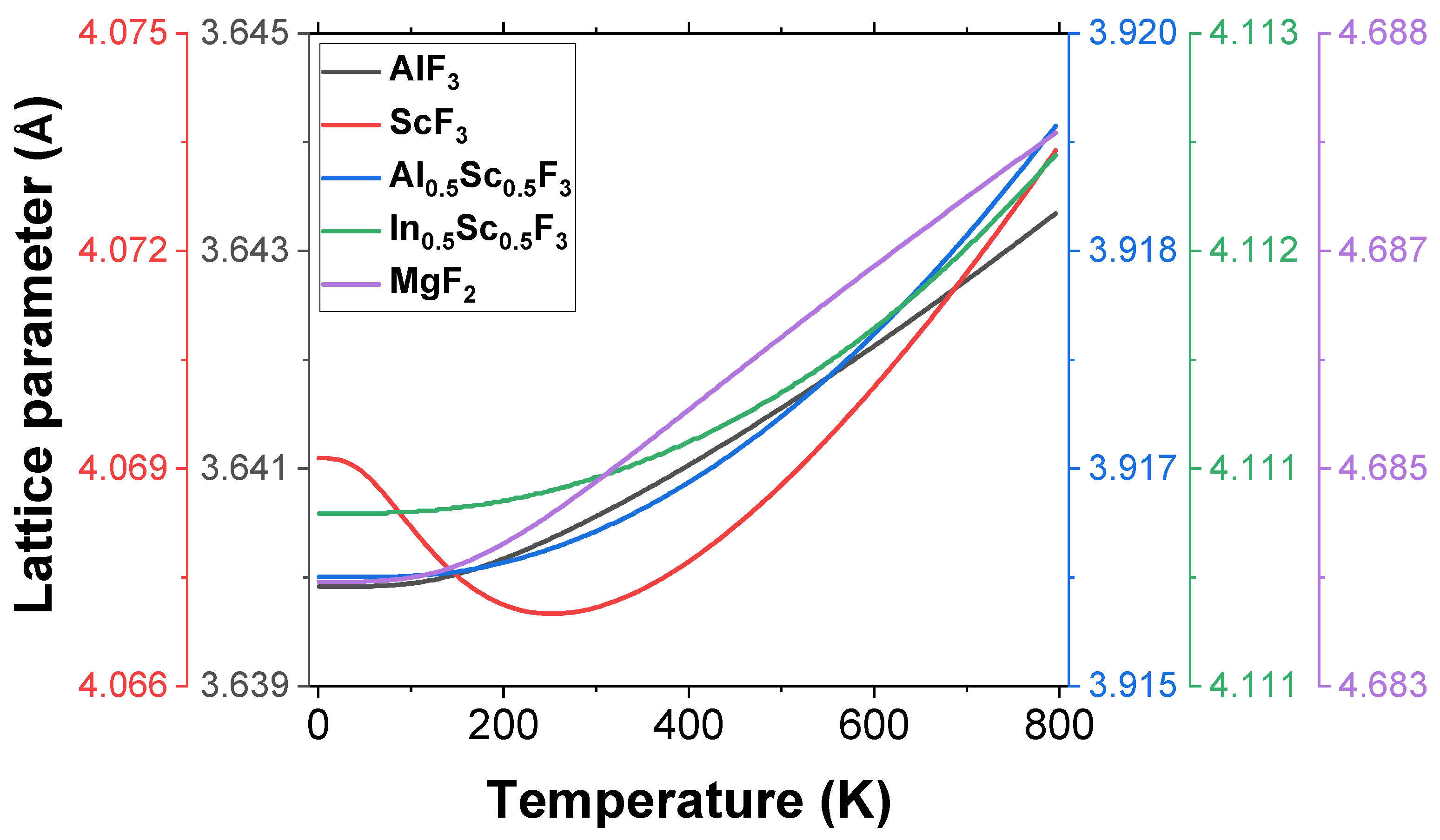
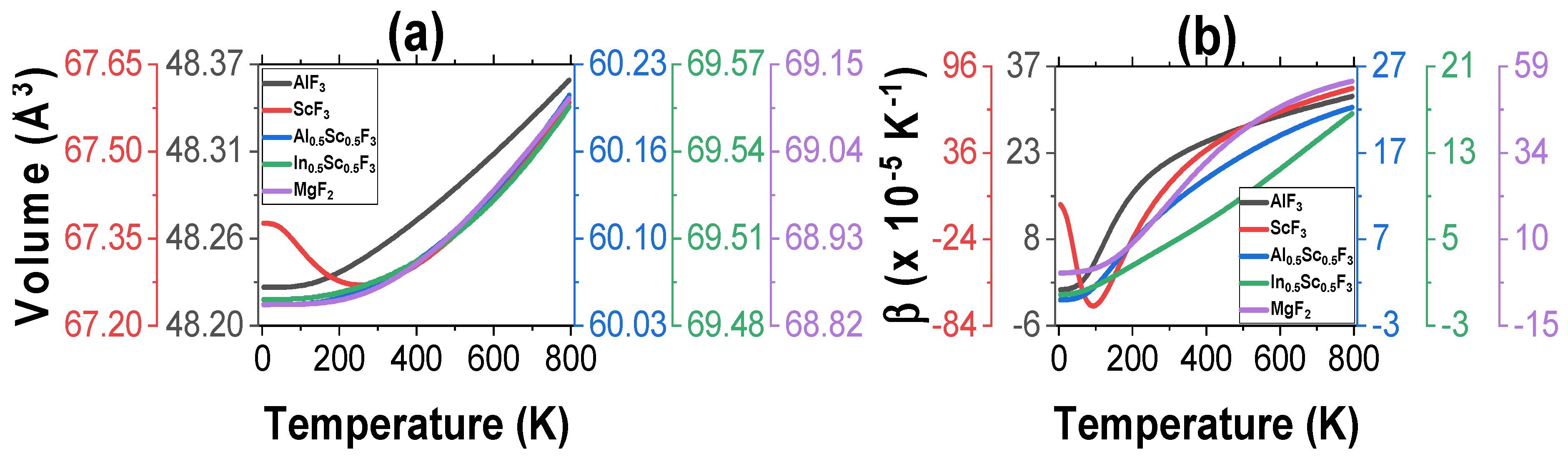
3.1. Structural Properties

Table 1 shows the computed unit cell parameters and the densities of the four materials that were investigated in this study, together with that of M g F 2 . The values were obtained at the ground state. The lattice parameter of A l F 3 was found to be 0.4458% higher than the reference value of 3.589 Å (from the Materials Project website), demonstrating that the cell expanded after complete relaxation. The S c F 3 , on the other hand, recorded a negative deviation of 0.0272% from the reference value of 4.039 Å, which shows that the cell contracted upon full relaxation. The computed values of the lattice parameters in this study are in good accord with those that exist in the literature, with that of A l F 3 being 2.185% higher than the value from the work by Alonso et al. [27]. The value for S c F 3 was also found to be in excellent agreement with both the computational values at 0.795% by Sifuna et al. [28] and −0.443% to 0.795% by Bucharov et al. [29], and the experimental value at −0.196% by Morelock et al. [30], as is evident in Table 1. The computed lattice parameters of M g F 2 also agree very well with those that exist in the literature, with parameter a being 1.038% higher than that from the experimental study by Haines et al. [31], and 1.309% lower than the computational value from the study by Babu et al. [32], who employed GGA in their calculations. The closeness of the computed values in this study with those that exist in the literature is a good indication that GGA produces sufficiently accurate results. The samples A l 0.5 S c 0.5 F 3 and I n 0.5 S c 0.5 F 3 were generated in this study for the first time, and therefore, their lattice parameters and densities do not exist in the literature for comparison.
A study by Sifuna et al. [28] found the density of S c F 3 to be quite close to the value obtained in this study. The densities of A l F 3 and M g F 2 were also found to be in agreement with those that are available in the literature, representing differences of 1.563% [33] and 2.606% [34], respectively. The addition of indium to the S c F 3 lattice was found to increase both the lattice parameter and the density (sample I n 0.5 S c 0.5 F 3 ) compared to the addition of aluminum (sample A l 0.5 S c 0.5 F 3 ), as can be observed in Table 1. This was expected, since the atomic radius of indium (at 156 pm) is larger than that of aluminum (at 118 pm).

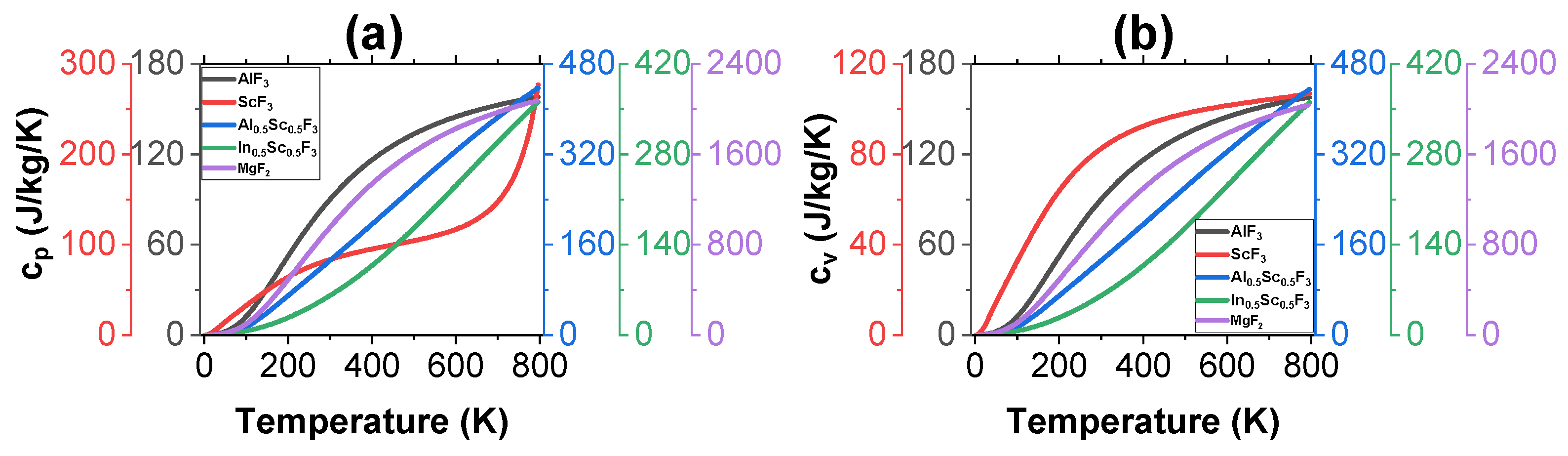
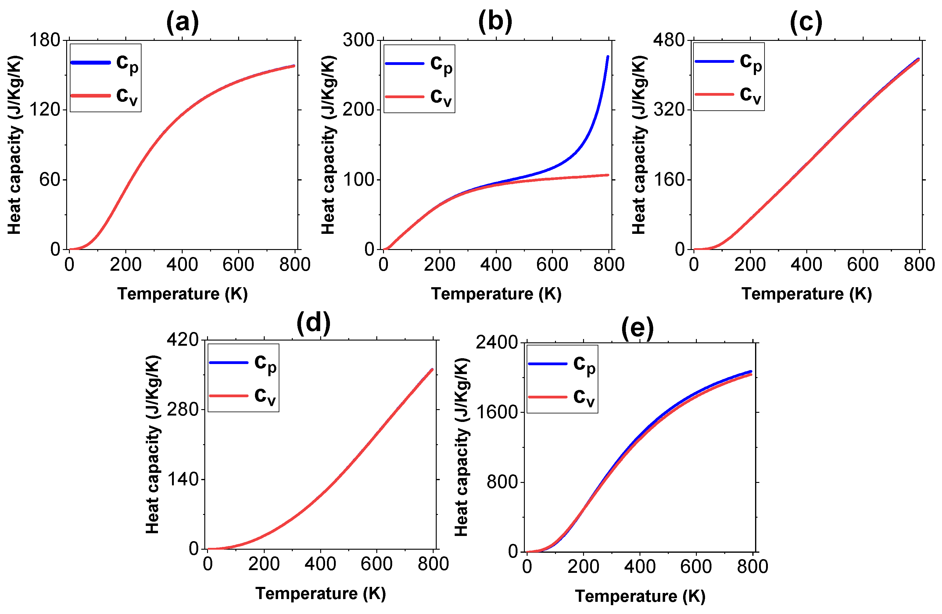
3.2. Thermal Properties

The fluctuation of the lattice parameter with temperature for each of the four samples, together with that of M g F 2 , is shown in Figure 2. The lattice parameter refers to the spacing between the repeating units (atoms, ions, or molecules) in a crystal lattice. In general, an increase in temperature causes an increase in the lattice parameter [35]. As Figure 2 depicts, the lattice parameters of A l F 3 , A l 0.5 S c 0.5 F 3 , I n 0.5 S c 0.5 F 3 , and M g F 2 increased consistently with an increase in temperature. This phenomenon can be explained by many factors, including thermal expansion, where the atoms or ions in the crystal lattice gain kinetic energy, leading to increased vibrations and a greater average interatomic/interionic distance, causing the lattice parameter to increase. At higher temperatures, the vibrational motion of atoms becomes more complex and anharmonic, meaning that the atoms oscillate not just around their equilibrium positions, but also exhibit larger-amplitude oscillations. These anharmonic effects can lead to an increase in the average distance between the atoms in the lattice, which contribute to the expansion. The complex and anharmonic vibrations can be the reason why the lattice parameters increase rapidly at higher temperatures (steeper slopes of the curves) than at lower temperatures (Figure 2). This observation can also be attributed to the complex and anharmonic vibrations, which refer to the types of vibrational motion in physical systems that deviate from simple harmonic motion. Complex vibrations occur when the restoring force is not strictly proportional to displacement, and the motion is not a simple sinusoidal oscillation. This can happen in real-world systems due to various factors like non-linear forces, damping, and multiple coupled oscillators. Complex vibrations can exhibit more intricate and irregular motion compared to simple harmonic motion. Anharmonic vibrations are a specific type of complex vibration, where the restoring force does not follow Hooke’s Law or any other linear relationship with displacement, and it may involve higher-order terms in the displacement. Anharmonic vibrations are commonly encountered in molecular vibrations and crystal lattice vibrations where interatomic forces are not linear and can involve various terms.
The S c F 3 sample experienced a decrease in the lattice parameter with temperature (at lower temperatures), a phenomenon called negative thermal expansion (NTE). The NTE in S c F 3 has also been observed in previous studies [28,36]. NTE is a relatively rare phenomenon, where the volume or linear dimensions of a material decrease with increasing temperature. NTE is an interesting and counterintuitive property that has attracted significant scientific interest. Figure 3a,b, which show the volume and volume thermal expansion coefficients, respectively, against temperature, show that the volumes and thermal expansion coefficients of A l F 3 , A l 0.5 S c 0.5 F 3 , I n 0.5 S c 0.5 F 3 , and M g F 2 increase with an increase in temperature within the whole temperature range, while those of S c F 3 decreased (NTE), especially at low temperatures. The increase in the lattice parameters of M g F 2 as temperature increases has also been reported by Sun et al. [37].
There are several mechanisms that can cause NTE in materials, including framework flexibility, where some materials, particularly those with open framework structures, may exhibit NTE due to the flexibility of their crystal lattice. When heated, these materials may undergo structural changes that cause the lattice to contract along specific directions, leading to NTE. Also, certain materials contain atoms that are loosely bound within their crystal structures, known as “rattling atoms”. When the material is heated, the rattling atoms experience increased thermal energy, leading to an expansion in certain directions and a contraction in others, resulting in an overall NTE effect. Order–disorder transitions may also lead to this phenomenon, which involves rearrangement of atoms or molecules in a way that leads to a contraction of the lattice [38,39].
Optical systems often experience temperature fluctuations during operation or in different environmental conditions. When the temperature changes, the materials in the optical coatings expand or contract accordingly. Figure 3b shows the thermal expansion coefficients of all the materials investigated in this study, which clearly indicates that while the thermal expansion coefficients of the other four materials increased with temperature increase, S c F 3 experiences a drop at low temperatures, reaching the minimum of a negative at 100 K. After that, the there is a consistent increase in the volume thermal expansion. S c F 3 exhibited the highest coefficient of thermal expansion within the temperature range, while I n 0.5 S c 0.5 F 3 exhibited the least. The coefficient of thermal expansion of M g F 2 was found to be very high, which is only second to that of S c F 3 .
High thermal conductivity is beneficial for optical coatings used in high-power laser systems or other applications with significant heat generation [40]. Thus, A l F 3 becomes the best candidate for coating such systems, since it has the highest thermal expansion among the four materials investigated in this study (Table 2). M g F 2 comes second. However, if the thermal expansion coefficients of the materials in the coating and the substrate are significantly different, it can cause mechanical stress and deformation, leading to coating delamination or distortion. Thus, the thermal expansion coefficient of the substrate on which the film coat is to be applied should be carefully investigated, especially for coatings used in non-demanding or low-temperature applications. Thermal expansion coefficient of common soda-lime glass (which is among the most common substrates for applying the optical coatings) is 8–9 × 10⁻⁶ K [41], which is comparable to that of A l 0.5 S c 0.5 F 3 (Table 2). It is usually determined between room temperature (298 K) to about 423 K. For high-performance optical systems and demanding applications, considering the thermal expansion coefficient becomes crucial to ensure long-term reliability and functionality of the optical coatings. It is evident from Figure 2 that the volume thermal expansion values obtained in this study are well in accord with those from previous studies, including that of M g F 2 . The values for A l 0.5 S c 0.5 F 3 and I n 0.5 S c 0.5 F 3 were found to be the lowest, although they are still comparable to that of glass.
Figure 4a,b depict how the specific heat capacity of the five materials change as a function of temperature, which shows that both c p and c v increase with an increase in temperature for all the materials, as well as M g F 2 . The quantity of heat energy needed to raise the temperature of a unit mass of a substance by one Kelvin is measured as the specific heat capacity. Furthermore, a material’s capacity to conduct heat is determined by its thermal conductivity. This is a measure of the rate of heat transfer through a substance per unit temperature gradient. There is no direct dependence between the two; both are material-dependent properties, and they can both influence the behavior of a material in response to temperature change. Materials with a high specific heat capacity require more heat energy to raise their temperature, while materials with high thermal conductivity are more effective at transferring heat, and have better thermal dissipation capabilities [45].
In the context of optical coatings, a higher specific heat capacity is generally not a desirable property, since it means that the material can store more heat energy per unit mass or volume [46]. When an optical coating absorbs and retains significant amounts of heat energy, it can lead to several undesirable consequences such as thermal distortion, where the heat energy absorbed by the coating material can cause local temperature gradients within it, leading to thermal expansion and distortion. This thermal distortion can affect the precision and performance of optical components, causing image degradation, wavefront aberrations, or shifts in the optical properties. A higher specific heat capacity can also lead to coating damage, where excessive heat absorption by the coating can cause localized heating and thermal stress. This can lead to coating delamination, cracking, or other forms of degradation, thus reducing the coating’s durability and lifespan [47].
Thermal conductivity is likewise an important consideration for optical coatings. High thermal conductivity allows the coating to efficiently dissipate heat and distribute it over a larger area or to the substrate, helping in mitigating temperature-related issues. Overall, when selecting materials for optical coatings, a low specific heat capacity and high thermal conductivity are generally preferred in order to ensure the stability, performance, and durability of the coatings in optical systems, since a low specific heat capacity means that they can quickly dissipate and release absorbed heat energy, thus reducing temperature-related effects [48]. Thin films with low thermal mass are preferred to minimize the amount of heat stored within the coating material. Thus, I n 0.5 S c 0.5 F 3 was found to be the best candidate for optical coatings in this regard, since it has the lowest values of the specific heat capacity, while A l 0.5 S c 0.5 F 3 was found to be the worst, since it had the largest value (Table 3). It was found out that both A l F 3 and S c F 3 , which are already commonly used in optical coatings, have comparable values of specific heat capacities, but the values are inferior to that of I n 0.5 S c 0.5 F 3 (Table 3).
Figure 5 compares the specific heat capacity for each of the four materials at constant volume and pressure with respect to temperature. All four materials show that the two types of specific heat capacity are almost equal at low temperatures. As temperature increases, however, variations are observed. This is explained by the fact that at high temperatures, variations in specific heat result primarily from variations in how heat is absorbed or released during a process with constant pressure ( c p ) compared to the process with constant volume ( c v ). At high temperatures, the increase in molecular degrees of freedom and interactions causes c p to increase more rapidly than c v . This is because at constant pressure, heat not only contributes to the material’s internal energy, but it also performs work in expanding the material against the pressure, leading to additional heat absorption. On the other hand, at constant volume, there is no work performed, and so, the increase in specific heat is less pronounced [49].
The variation between the two specific heat capacities at high temperatures is more pronounced for S c F 3 , which means that it can absorb more heat energy when heated at constant pressure compared to when heated at constant volume. This difference in heat absorption can influence the temperature distribution and thermal stress within the coating material during deposition and post-processing steps, potentially affecting the coating’s optical properties and overall performance. A large variation between c p and c v can affect the temperature stability of the coating material. For instance, when the coating experiences temperature changes, the material with a large c p c v difference may respond differently in terms of thermal expansion and contraction, potentially leading to mechanical stresses that can degrade the optical performance, or even cause delamination or cracking of the coating. Thus, S c F 3 is not suitable as a coating material in this regard. M g F 2 also experienced a noticeable variation between the two specific heat capacities, as can be observed in Figure 5e. It is therefore also not an ideal coating material in this regard. The computed values of specific heat capacity at constant pressure obtained in this study are in good accord with the existing values in the literature, as can be observed in Table 3.
Table 3. The calculated thermal properties of the 4 materials and M g F 2 at room temperature (298) for c p , c v , and δ T . c p and c v are shown in J/kg/K, while δ T is shown in GPa.
Material c p ( J / K ) c v ( J / K ) δ T   ( × 10 3 )
A l F 3 80.73 (75.1) [50]79.71(−4.38)–(−5.15)
S c F 3 82.21 (83.5) [51]81.15(−19.2)–(−28.67)
A l 0.5 S c 0.5 F 3 120.40119.35(−2.33)–(−3.58)
I n 0.5 S c 0.5 F 3 56.2155.23(−0.684)–(−1.34)
M g F 2 955.6 (980) [8]951.1-
Thermal stress is a crucial consideration in the design and performance of optical coatings. The optical coatings are typically applied to substrates made of different materials, each with its own coefficient of thermal expansion [52]. When there is a temperature change, the coating and substrate will expand or contract at different rates, leading to differential thermal expansion. This can result in significant thermal stress at the interface between the coating and the substrate. Thus, managing thermal stress in optical coatings is critical to ensure the coating’s performance, adherence, and long-term durability.
Thermal stress typically increases as temperature increases in most materials, especially for materials with positive coefficients of thermal expansion [53] This is due to the fact that a material’s coefficient of thermal expansion determines how much it will expand or contract in response to a change in temperature. Moreover, when a material is subjected to temperature changes, it tends to expand or contract freely. However, if it is constrained or bonded to another material with a different coefficient of thermal expansion, it cannot freely expand or contract. The material begins to experience thermal stress as a result of this constraint. As Figure 6 depicts, the thermal stress of the four materials in this study were found to decrease consistently with an increase in temperature. This is a rare phenomenon, and can be attributed to many factors, including phase transitions, material softening, and coefficient of thermal expansion. Some materials undergo phase transitions at specific temperatures, and during the phase transitions, the material may experience changes in its internal structure, crystal lattice, or other physical properties. These changes can result in stress-relief mechanisms that offset the increase in thermal stress that would typically be expected with temperature rise. Other materials may also experience softening or a decrease in Young’s modulus with increasing temperature. Since thermal stress is proportional to the Young’s modulus, a decrease in the Young’s modulus can lead to a decrease in thermal stress as temperature rises [54].
All four materials explored in this study show negative values of thermal stress (Table 3), which is also a rare phenomenon, and can have both significant practical implications and theoretical importance in the study of materials and their behavior under thermal loads, including stress relief and prevention of cracking. Negative thermal stress is good for optical coatings, since it leads to improved adhesion on to the substrate, compensation for substrate stress, and thermal stability, especially in applications where the optical component experiences significant temperature fluctuations or rapid changes in operating conditions. S c F 3 was found to have the highest negative value of the thermal stress, while I n 0.5 S c 0.5 F 3 was found to have the lowest. Thus, S c F 3 is the best of all four materials explored in this study with regards to thermal stress.

4. Conclusions

The comparison of the thermal properties of A l F 3 , S c F 3 , A l 0.5 S c 0.5 F 3 , and I n 0.5 S c 0.5 F 3 was successfully made. The study found out that the calculated values of the thermal properties are well in accord with the literature data. It was also found out that thermal expansion coefficients of the materials increased with temperature at low temperatures, except that of S c F 3 , which experienced a negative temperature coefficient of thermal expansion. This was attributed to rattling atoms, and order–disorder transitions. A l F 3 had the best thermal expansion coefficient. I n 0.5 S c 0.5 F 3 , on the other hand, had the lowest value of coefficient of thermal expansion. The negative coefficient of thermal expansion of S c F 3 indicates that it is not thermally stable, especially at low temperatures, while I n 0.5 S c 0.5 F 3 is the most stable. It was also found out that I n 0.5 S c 0.5 F 3 has the lowest values of c p and c v of all four materials, while A l 0.5 S c 0.5 F 3 has the highest. The lowest values of c p and c v for I n 0.5 S c 0.5 F 3 are good for optical coating applications. While c p and c v were found to be almost equal for A l F 3 , A l 0.5 S c 0.5 F 3 , and I n 0.5 S c 0.5 F 3 , this was not the case for S c F 3 , which showed a large variation between the two quantities, especially at high temperatures. This was attributed to the molecular degree of freedom and interactions. The specific heat capacity of M g F 2 was found to be much higher than those of the rest, which is not a desirable property for optical coatings, since it leads to thermal distortion and shifts in optical properties. The thermal stresses of all the materials were found to decrease with an increase in temperature, with S c F 3 recording the lowest value, while I n 0.5 S c 0.5 F 3 recorded the highest value. The S c F 3 sample was thus found to be good for coatings that are used in high-power laser systems with high thermal dissipation, owing to its good thermal expansion coefficient as well as lowest thermal stress. I n 0.5 S c 0.5 F 3 is only better than A l F 3 due to its lowest values of c p and c v , which are good for most optical coating applications, since higher values of the two parameters can lead to undesirable effects such as thermal distortion or fluctuations in the optical properties of the coating. However, thermal properties alone are not enough for a complete understanding of materials. Thus, other properties such as mechanical and optical need to be investigated for the four materials, considering these properties are also essential to the operation of optical coatings. Moreover, this study carried out a computational investigation of the thermal properties. Experimental treatment of the materials can form a basis for future work in order to verify the results.

Author Contributions

Conceptualization, A.B.A.; methodology, N.O.O.; software, N.O.O.; validation, A.B.A.; formal analysis, A.B.A. and N.O.O.; investigation, A.B.A. and N.O.O.; resources, A.B.A. and N.O.O.; data curation, A.B.A. and N.O.O.; writing—original draft preparation, A.B.A. and N.O.O.; writing—review and editing, A.B.A.; visualization, A.B.A. All authors have read and agreed to the published version of the manuscript.

Funding

This research work was funded by Institutional Fund Projects under grant no. (IFPIP:1545-130-1443). The authors gratefully acknowledge technical and financial support provided by the Ministry of Education and King Abdulaziz University, DSR, Jeddah, Saudi Arabia.

Institutional Review Board Statement

Not applicable.

Informed Consent Statement

Not applicable.

Data Availability Statement

The data regarding this study are available on request.

Conflicts of Interest

The authors declare no conflict of interest.

References

  1. Piegari, A.; Flory, F. Optical Thin Films and Coatings: From Materials to Applications; Series in Electronic and Optical Materials; Woodhead Publishing: Cambridge, UK, 2008. [Google Scholar]
  2. Thelen, A. Design strategies for thin film optical coatings. In Thin Films on Glass; Bach, H., Krause, D., Eds.; Schott Series on Glass and Glass Ceramics; Springer: Berlin/Heidelberg, Germany, 2003. [Google Scholar] [CrossRef]
  3. Stenzel, O. Optical Coatings: Material Aspects in Theory and Practice; Springer: Berlin/Heidelberg, Germany, 2014. [Google Scholar] [CrossRef]
  4. Ristau, D.; Ehlers, H. Thin Film Optical Coatings. In Springer Handbook of Lasers and Optics; Träger, F., Ed.; Springer: New York, NY, USA, 2007. [Google Scholar] [CrossRef]
  5. Lisitsyn, V.M.; Lisitsyna, L.A.; Popov, A.I.; Kotomin, E.A.; Abuova, F.U.; Akilbekov, A.; Maier, J. Stabilization of primary mobile radiation defects in MgF2 crystals. Nucl. Instrum. Methods Phys. Res. Sect. B Beam Interact. Mater. At. 2016, 374, 24–28. [Google Scholar] [CrossRef]
  6. Pankratova, V.; Purans, J.; Pankratov, V. Low-temperature luminescence of ScF3 single crystals under excitation by VUV synchrotron radiation. Low Temp. Phys. 2020, 46, 1196–1200. [Google Scholar] [CrossRef]
  7. Fritz, C.; Scholz, G.; Feista, M.; Kemnitz, E. Preparation and stabilization of aluminium trifluoroacetate fluoride sols for optical coatings. Dalton Trans. 2007, 41, 11351–11360. [Google Scholar] [CrossRef] [PubMed]
  8. Cotter, T.M.; Thomas, M.E.; Tropf, W.J. Magnesium Fluoride (MgF2). In Handbook of Optical Constants of Solids; Palik, E.D., Ed.; Academic Press: London, UK, 1997; pp. 899–918. [Google Scholar] [CrossRef]
  9. Golota, A.F.; Khoroshilova, S.E.; Tarala, L.V.; Evtushenko, E.A. Compacted magnesium fluoride: Preparation, characterization, and optics. Russ. J. Inorg. Chem. 2019, 64, 705–709. [Google Scholar] [CrossRef]
  10. Uy, A. Atomic Layer Deposition of Aluminum Fluoride for Use in Optical Devices. Ph.D. Thesis, University of Maryland, College Park, MD, USA, 2022. [Google Scholar] [CrossRef]
  11. Hennessy, J.; Jewell, A.D.; Balasubramanian, K.; Nikzad, S. Ultraviolet optical properties of aluminum fluoride thin films deposited by atomic layer deposition. J. Vac. Sci. Technol. A 2016, 34, 01A120. [Google Scholar] [CrossRef]
  12. Chernoburova, O.; Chagnes, A. The future of scandium recovery from wastes. Mater. Proc. 2021, 5, 55. [Google Scholar] [CrossRef]
  13. Smith, W.J. Modern Optical Engineering, 3rd ed.; McGraw-Hill: New York, NY, USA, 2000. [Google Scholar]
  14. Paschotta, R. Optical Materials. RP Photonics Encyclopedia. Available online: https://www.rp-photonics.com/optical_materials.html (accessed on 11 August 2023).
  15. Hołyńska, M.; Tighe, A.; Semprimoschnig, C. Coatings and thin films for spacecraft thermo-optical and related functional applications. Adv. Mater. Interfaces 2018, 5, 1701644. [Google Scholar] [CrossRef]
  16. Materials Project Database. Available online: https://next-gen.materialsproject.org/materials (accessed on 11 August 2023).
  17. Giannozzi, P.; Baroni, S.; Bonini, N.; Calandra, M.; Car, R.; Cavazzoni, C.; Ceresoli, D.; Chiarotti, G.L.; Cococcioni, M.; Dabo, I.; et al. Quantum espresso: A modular and open-source software project for quantum simulations of materials. J. Phys. Condens. Matter 2009, 21, 395502. [Google Scholar] [CrossRef]
  18. Monkhorst, H.J.; Pack, J.D. Special points for Brillouin zone integration. Phys. Rev. B. 1976, 13, 1592–5188. [Google Scholar] [CrossRef]
  19. Taylor, R.E. Thermal Expansion of Solids; ASM International: Detroit, MI, USA, 1998. [Google Scholar]
  20. Drebushchak, V.A. Thermal expansion of solids: Review on theories. J. Therm. Anal. Calorim. 2020, 142, 1097–1113. [Google Scholar] [CrossRef]
  21. Allen, P. Theory of thermal expansion: Quasi-harmonic approximation and corrections from quasi-particle renormalization. Mod. Phys. Lett. B 2020, 34, 2050025. [Google Scholar] [CrossRef]
  22. Kittel, C. Introduction to Solid State Physics; John Wiley and Sons: New York, NY, USA, 2005. [Google Scholar]
  23. Degheidy, A.R.; Elkenany, E.B.; Madkour, M.; AbuAli, A.M. Temperature dependence of phonons and related crystal properties in InAs, InP and InSb zinc-blende binary compounds. Comput. Condens. Matter. 2018, 16, e00308. [Google Scholar] [CrossRef]
  24. Baroni, S.; Giannozzi, P.; Isaev, E. Density-functional perturbation theory for quasi-harmonic calculations. Rev. Mineral. Geochem. 2010, 71, 39–57. [Google Scholar] [CrossRef]
  25. Togo, A.; Tanaka, I. First principles phonon calculations in materials science. Scr. Mater. 2015, 108, 1–5. [Google Scholar] [CrossRef]
  26. Barron, R.F.; Barron, B.R. Design for Thermal Stresses; John Wiley & Sons Inc.: Hoboken, NJ, USA, 2012. [Google Scholar]
  27. Alonso, C.; Morato, A.; Medina, F.; Guirado, F.; Cesteros, Y.; Salagre, P.; Sueiras, J.E. Preparation and characterization of different phases of aluminum trifluoride. Chem. Mater. 2000, 12, 1148–1155. [Google Scholar] [CrossRef]
  28. Sifuna, J.; Manyali, G.S.; Sakwa, T.; Kitui, M.M. Structural and mechanical properties of bulk scandium trifluoride investigated by first-principles calculations. J. Multidiscip. Eng. Sci. Technol. 2017, 4, 6667–6668. [Google Scholar]
  29. Bocharov, D.; Žguns, P.; Piskunov, S.; Kuzmin, A.; Purans, J. Electronic structure of cubic ScF3 from first-principles calculations. Fiz. Nizk. Temp. 2017, 42, 710–715. [Google Scholar] [CrossRef]
  30. Morelock, C.R.; Gallington, L.C.; Angus, W.P. Evolution of negative thermal expansion and phase transitions in Sc1−xTixF3. Chem. Mater. 2014, 26, 1936–1940. [Google Scholar] [CrossRef]
  31. Haines, J.; Gorelli, F.A.; Klung, D.; Tse, J. X-ray diffraction and theoretical studies of the high-pressure structures and phase transitions in magnesium fluoride. Phys. Rev. Lett. 2001, 64, 134110. [Google Scholar] [CrossRef]
  32. Babu, R.K.; Lingam, C.B.; Auluck, S.; Tewari, S.P. Structural, thermodynamic and optical properties of MgF2 studied from first-principles theory. J. Solid State Chem. 2011, 184, 343–350. [Google Scholar] [CrossRef]
  33. U.S. Coast Guard. Chemical Hazard Response Information System (CHRIS)—Hazardous Chemical Data; Government Printing Office: Washington, DC, USA, 1999. [Google Scholar]
  34. Patnaik, P. Handbook of Inorganic Chemicals; McGraw-Hill: New York, NY, USA, 2002. [Google Scholar]
  35. Busk, R.S. Effect of temperature on the lattice parameters of magnesium alloys. JOM 1952, 4, 207–209. [Google Scholar] [CrossRef]
  36. Gulina, L.B.; Tolstoy, V.P.; Kasatkin, I.A.; Murin, I.V. Facile synthesis of scandium fluoride oriented single-crystalline rods and urchin-like structures by a gas–solution interface technique. CrystEngComm 2017, 19, 5412–5416. [Google Scholar] [CrossRef]
  37. Sun, X.W.; Song, T.; Wei, X.P.; Quan, W.L.; Liu, X.B.; Su, W.F. Thermal stability and thermal expansion studies of cubic fluorite-type MgF2 up to 135GPa. Mater. Res. Bull. 2014, 52, 151–157. [Google Scholar] [CrossRef]
  38. Er-Jun, L.; Sun, Q.; Yuan, H.; Wang, J.; Zeng, G.; Gao, Q. Negative thermal expansion: Mechanisms and materials. Front. Phys. 2021, 16, 53302. [Google Scholar] [CrossRef]
  39. Wang, J.; Xu, P.; Yuan, H.; Gao, Q.; Sun, Q.; Er-Jun, L. Negative thermal expansion driven by acoustic phonon modes in rhombohedral Zn2GeO4. Results Phys. 2020, 19, 103531. [Google Scholar] [CrossRef]
  40. Ravindra, N.M.; Marthi, S.R.; Bañobre, A. Optical and thermal properties. In Radiative Properties of Semiconductors; Morgan & Claypool Publishers: San Rafael, CA, USA, 2017. [Google Scholar]
  41. Lunkenheimer, P.; Loidl, A.; Riechers, B.; Zaccone, A.; Samwer, K. Thermal expansion and the glass transition. Nat. Phys. 2023, 19, 694–699. [Google Scholar] [CrossRef]
  42. Haynes, W.M. (Ed.) CRC Handbook of Chemistry and Physics, 92nd ed.; CRC Press: Boca Raton, FL, USA, 2011. [Google Scholar] [CrossRef]
  43. Greve, B.K.; Martin, K.L.; Lee, P.L.; Chupas, P.J.; Chapman, K.W.; Wilkinson, A.P. Pronounced negative thermal expansion from a simple structure: Cubic ScF3. J. Am. Chem. Soc. 2010, 132, 15496–15498. [Google Scholar] [CrossRef]
  44. Rao, K.V.; Naidu, S.V.; Setty, P.L.N. Thermal expansion of magnesium fluoride. Acta Cryst. 1962, 15, 528–530. [Google Scholar] [CrossRef]
  45. Abe, H. National standard and new reference material for specific heat capacity measurements. Anal. Sci. 2021, 37, 201–210. [Google Scholar] [CrossRef]
  46. Krastev, R.K. Measuring of heat capacity. Int. J. Heat Mass Transf. 2010, 53, 3847–3854. [Google Scholar] [CrossRef]
  47. Trevisan, S.; Wang, W.; Laumert, B. A high-temperature thermal stability and optical property study of inorganic coatings on ceramic particles for potential thermal energy storage applications. Sol. Energy Mater. Sol. Cells 2022, 239, 111679. [Google Scholar] [CrossRef]
  48. Redondo, A.; Beery, J.G. Thermal conductivity of optical coatings. J. Appl. Phys. 1986, 60, 3882–3885. [Google Scholar] [CrossRef]
  49. Smith, N.O. The difference between Cp and Cv for liquids and solids. J. Chem. Educ. 1954, 42, 654. [Google Scholar] [CrossRef]
  50. Lide, R.D. (Ed.) CRC Handbook of Chemistry and Physics, 81st ed.; CRC Press LLC.: Boca Raton, FL, USA, 2000. [Google Scholar]
  51. Aristovaa, N.M.; Belov, G.V. Thermodynamic parameters of scandium trifluoride and triiodide in the condensed state. Russ. J. Phys. Chem. 2015, 89, 947–951. [Google Scholar] [CrossRef]
  52. Nakajima, Y.; Tanaka, H.; Mochizuki, K.; Fuse, K.; Arashitani, Y.; Nishimoto, T.; Seno, A.; Okada, M. A study for estimating thermal strain and thermal stress in optical fiber coatings. Furukawa Rev. 2008, 34, 8–12. [Google Scholar]
  53. Kodur, V.R.; Sultan, M.A. Effect of temperature on thermal properties of high-strength concrete. J. Mater. 2003, 15, 101–107. [Google Scholar] [CrossRef]
  54. Ren, H.; Zou, G.; Jia, Q.; Deng, Z.; Du, C.; Wang, W.; Liu, L. Thermal stress reduction strategy for high-temperature power electronics with Ag sintering. Microelectron. Reliab. 2021, 127, 114379. [Google Scholar] [CrossRef]
Figure 1. The 3D structures of the input files: (a) aluminum trifluoride, (b) scandium trifluoride, (c) aluminum–scandium trifluoride, (d) indium–scandium trifluoride, and (e) magnesium fluoride. Aluminum atoms are represented by the gray balls, fluorine atoms by the green balls, indium atoms by the blue balls, scandium atoms by the red balls, and magnesium atoms by the purple balls.
Coatings 13 01840 g001
Figure 2. The calculated lattice parameter of the 4 materials, together with that of M g F 2 as a function of temperature.
Coatings 13 01840 g002
Figure 3. The calculated (a) unit cell volumes, and (b) volume thermal expansion coefficients of the 4 materials and M g F 2 as a function of temperature.
Coatings 13 01840 g003
Figure 4. The calculated specific heat capacities (a) at constant pressure, and (b) at constant volume of the 4 materials, together with that of M g F 2 as a function of temperature.
Coatings 13 01840 g004
Figure 5. The calculated specific heat capacities of (a) A l F 3 , (b), S c F 3 , (c) A l 0.5 S c 0.5 F 3 , (d) I n 0.5 S c 0.5 F 3 , and (e) M g F 2 as a function of temperature.
Coatings 13 01840 g005
Figure 6. Thermal stress of the 4 materials as a function of temperature.
Coatings 13 01840 g006
Table 1. The computed lattice parameters of all the five materials at the ground state and the densities of A l F 3 , S c F 3 , A l 0.5 S c 0.5 F 3 , I n 0.5 S c 0.5 F 3 , and M g F 2 .
Sample A l F 3 S c F 3 A l 0.5 S c 0.5 F 3 I n 0.5 S c 0.5 F 3 M g F 2
a ( Å ) 3.6051 (3.528) [27]4.0379 (4.07, 4.02–4.07, 4.03) [28,29,30]3.89434.08674.673
(4.625, 4.735) [31,32]
c ( Å ) ----3.082
(3.052, 3.124) [29,30]
ρ ( g / c m 3 ) 2.925 (2.88) [33]2.546 (2.44–2.61) [28]2.6743.1153.070 (3.15) [34]
Table 2. The computed values of the volume thermal expansion coefficients (β) of the 4 materials and M g F 2 at room temperature (298 K).
Material β   ( × 10 6 K 1 )
A l F 3 20.427 (22) [42]
S c F 3 14.371 (14) [43]
A l 0.5 S c 0.5 F 3 10.793
I n 0.5 S c 0.5 F 3 4.6272
M g F 2 12.762 (12.1) [44]
Disclaimer/Publisher’s Note: The statements, opinions and data contained in all publications are solely those of the individual author(s) and contributor(s) and not of MDPI and/or the editor(s). MDPI and/or the editor(s) disclaim responsibility for any injury to people or property resulting from any ideas, methods, instructions or products referred to in the content.

