Abstract
In this paper, we investigated the behaviors of bubbles entrained in a film coating during spray coating. Air bubbles that remain in a film coating after diluent evaporation cause coating defects called bubbling defects, including fish-eye and crater defects. In this study, the visualization of a film coating revealed that smaller bubbles in the film shrank slowly and disappeared, while larger bubbles remained. These remaining bubbles grew during the heating process for the drying of the film coating. The shrinking phenomenon was explained using bubble dynamics based on the Young–Laplace equation of a bubble’s inner pressure and Henry’s law for bubble gas dissolution into the film coating. This shrinking model is often used in studies on microbubble dynamics. The results suggested the importance of avoiding the entrainment of large bubbles during the spraying process and enhancing the release of air bubbles from the film coating’s surface through the appropriate usage of defoaming agents.
1. Introduction
Coating technology is important, as coating is the final step of the manufacturing process of industrial products. Spray coating has been studied extensively in various industrial fields. Paint materials are spray-coated on large products, such as automobiles [1,2], ships [3,4], and airplanes [5]. Polymers are spray-coated on semiconductor wafers [6,7] and solar cells [8] using a similar technology. A film coating is formed by the spreading of spray droplets on a surface and the combination of these droplets. Film formation is strongly influenced by surface characteristics, such as the physical properties of the droplets, surface wettability, and the collision conditions of the droplets. Spray coating technology requires research and development to ensure the optimal formation of film coatings. In particular, it is necessary to not only ensure the sufficient quality of the coating surface but also to take measures to reduce volatile organic substances (VOCs) at the same time.
The VOCs emitted via coating processes in industrial fields should be reduced because VOCs negatively affect the environment and human health [9,10,11,12]. Toluene, xylene, and formaldehyde are typical VOC chemicals; they are vaporized in the temperature range of conventional environmental conditions and are easily diffused into the atmosphere. Suspended particulate matter and photochemical oxidants are generated from the exhaust gases of diesel engines and other fuel combustion facilities and the VOC gases of coating materials. VOCs also cause sick building syndrome [13,14]. In various manufacturing processes, ventilation and airflow control are implemented to prevent VOC damage [15,16,17]. Moreover, coating methods using water-based paints are being developed to control VOC emissions [18,19]. The utilization of high-pressure carbon dioxide as a solvent for paints was newly developed to reduce the VOC emissions from coating processes [20,21]. For VOC emission control, coating processes must be optimized to reduce paint consumption while maintaining surface quality.
The abovementioned problems in coating processes should be considered to ensure the quality of coated surfaces. Moreover, the prevention of coating defects is important because coating is the final step of the manufacturing process of a product and is related to product quality. Many studies have been conducted on the defects that occur on surfaces after coating. Various types of coating defects have physically different causes; these defects include craters, pinholes, and air bubbles in film coatings; debris entering from the exterior; and peeling or sagging [22,23]. Many papers have been published recently on the detection of paint defects using machine vision systems [24,25].
The formation mechanism of coating defects has been examined. For example, studies have been performed on the pinholes and crater defects that emerge during the drying process of film coatings [26,27]. Likewise, the entrapment of air bubbles in film coatings has been investigated. For example, the behaviors of air bubbles trapped on a film coating surface during spray painting was reported in detail [28]. Bubbles are released from the surface, and the number of bubbles gradually decreases, with larger bubbles being released more quickly than smaller bubbles. Detailed experimental and numerical studies have been conducted on the behaviors of bubbles trapped in liquids as they rise toward the liquid surface [29,30]. These studies showed that the thickness of the viscous film sandwiched between the bubbles and the liquid surface becomes thinner and bubbles are released from the liquid surface [31]. However, in the case of film coatings, many bubbles are not released; this is because of the enhanced paint viscosity and coating solidification (skinning) caused by solvent evaporation, which causes coating defects. Furthermore, the bubbles move due to convection flow and form clusters during the drying process of a film coating [32]. Then, due to heating in the drying process, the bubble diameter enlarges. Air bubbles that remain trapped in the film coating act as nucleation points of defects, and larger bubbles appear during the baking process. Therefore, bubble behavior in the coating process should be observed in detail.
In this study, the behaviors of bubbles entrained in a film coating are observed using clear paint. The results show that small bubbles shrink and disappear due to the high pressure within the bubbles, but larger bubbles shrink slowly. The remaining bubbles in the film coating expand during the baking process, leading to bubble defects.
2. Materials and Methods
Figure 1 shows the experimental apparatus, which consisted of a spray injector and an observation system for the film coating formation process. A pressure-feed spray gun (FA110-P08P, Meiji Air Compressor Manufacturing Co. Ltd., Osaka, Japan) was utilized as the injection nozzle. The spray gun was mounted on a single-axis robot and could move horizontally at different speeds. In this experiment, the moving speed of the spray gun was mainly set to VN = 50 mm/s. The nozzle hole diameter of the spray gun was 0.8 mm. A compressor with a reservoir tank was used to supply paint and air from the spray gun to the surface. The spray gun was connected to a pressurized tank containing paint through a feed hose. The compressed air was supplied to the spray gun through an air adjustment valve. The flow rate of the paint (Q = 180 mL/min) was set by adjusting the pressure in the pressurized tank. The airflow rate (Qair = 30.6 L/min) was also controlled using the air valve. The injection pressure was Pi = 0.25 MPa.
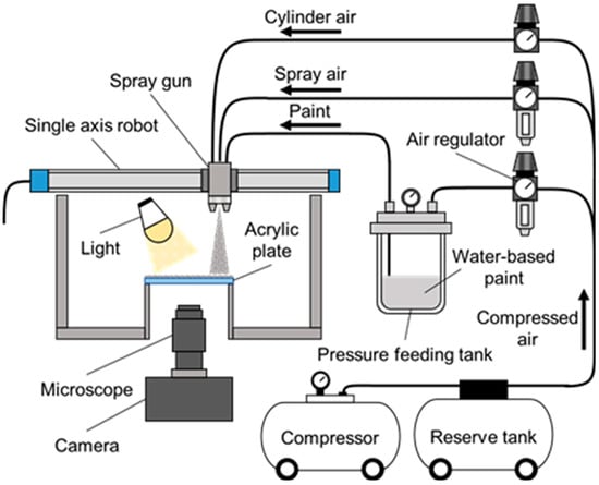
Figure 1.
Experimental apparatus.
Water-based clear paint was used in the experiment. Its viscosity, measured using a cup viscometer (NK-2, Anest Iwata Corp., Yokohama, Japan), was adjusted to μ = 0.10 Pa·s by changing the amount of added water. The mass ratio of the base paint, hardener, and added water was mainly set to 100:28:20. A transparent acrylic plate with a length of 100 mm, a width of 100 mm, and a thickness of 3 mm was used to observe the coating process. The paint was sprayed on the acrylic plate by moving the spray gun horizontally at a constant speed. The distance from the spray gun to the coated surface was set to DN = 250 mm. Water-based paints are sensitive to their environment. Differences in ambient conditions cause variations in the film coating formation process and the quality of the finished film coating surface. Therefore, all experiments in this study were conducted at a constant ambient temperature of Tair = 20 °C and a constant humidity of Hair = 50%. The experimental conditions are summarized in Table 1.

Table 1.
Experimental conditions.
The formation of the film coating on the acrylic plate was photographed from the underside of the acrylic plate using a digital camera (DCM-GH4, Panasonic Corp., Kadoma, Japan) with an attached microscope (VZM1000, Edmund Optics Japan Co. Ltd., Bunkyo-ku, Japan) [33,34] at 10 s intervals for 15 min.
We analyzed the behaviors of air bubbles entrained in the film coating. The number of bubbles and bubble radius at various times during the drying process were measured in the images of the film coating using the image analysis software, A-Zo Kun (Version 2.50, Asahi Kasei Engineering Corp., Kawasaki, Japan). Temporary changes in the bubble number and radii were derived from the analyzed images.
3. Results and Discussion
3.1. Changes in Bubble Number and Diameter Distribution
Figure 2 shows images of the air bubbles in the film coating, which were captured 10 s, 60 s, 120 s, and 240 s after spraying. Soon after spraying (t = 10 s), the film coating contained numerous bubbles of various sizes. The number of bubbles decreased with time; the smaller bubbles disappeared first, but the larger bubbles remained.
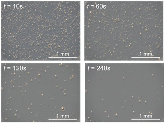
Figure 2.
Photographs of bubbles entrained in film coating.
Figure 3 shows the change in the number of bubbles over time. Each plot in the graph corresponds to the number of bubbles in a 1 mm square area in each image taken. The horizontal axis of the graph is the time, and the vertical axis is the number of bubbles at that time. The black plots are the data from three experiments, and the white plots are their average values. First, focusing on the number of bubbles at t = 10 s (immediately after spraying), we found variations between the experiments. Even when spray coating was performed under the same conditions, the number of bubbles that initially entered the film coating showed an inconsistent trend. The number of bubbles decreased with time, eventually reducing to zero or a small value. Under the experimental conditions of this study, the number of bubbles decreased to a small value at approximately t = 180 s.
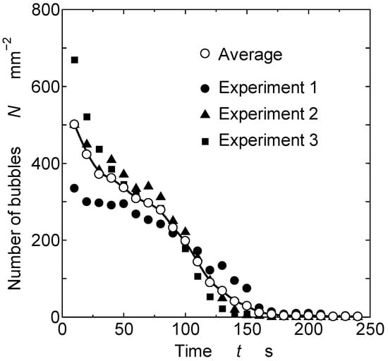
Figure 3.
Change in number of bubbles over time.
The bubbles disappeared for two reasons. First, the bubbles that were trapped in the film coating floated to the surface and were released from the surface into the atmosphere. This was confirmed by the observed bursting and disappearance of the bubbles during film coating formation. Second, the air in the bubbles gradually shrank and eventually dissolved into the film coating. This was verified by the observed gradual decrease in the bubbles’ diameters.
Some previous studies have been conducted on the release of bubbles from the film coatings. For example, Kadoura et al. observed that after spray coating, a large number of bubbles were entrapped into the film coating [32]. They also stated that the bubbles migrated to the surface of the film coating and disappeared after 4–5 min. Dalili et al. also observed in detail the release process of bubbles trapped in the film coating [28]. For coating thicknesses of less than 300 μm, the Sauter mean diameter of the bubbles decreased with time, which they attributed to the fact that the larger bubbles were released earlier than the smaller ones. They also observed that the bubbles disappeared suddenly without shrinking or collapsing. Since the bubbles did not appear to dissolve in the surrounding liquid, they concluded that the bubbles were bursting through the surface of the coating. They also mentioned the effect of the Marangoni convection caused by the surface tension gradient with solvent evaporation, in addition to the buoyancy, as a force that allows for bubbles to move to the coating surface. In these detailed studies, commercial solvent-based clear paint and model paint with resin and solvent mixtures were used. In our study, water-based paint was used, and the behaviors of the bubbles in the film coating may be different from those in previous works. In other words, the dissolving rate of the gas components in bubbles may differ between solvent-based and water-based paints.
Figure 4 shows the sample photographs of the shrinking and disappearance of bubbles in the film coating. It seemed that relatively small bubbles gradually became smaller and disappeared. This dissolving phenomenon of bubbles in film coating can be explained as the smaller bubbles had higher inside pressures due to surface tension, and the amount of dissolved gas became higher with higher pressure according to Henry’s law. Saranjam and Chandra discussed that the gas components of bubbles dissolved into the paint using Henry’s law [29]. As described below, in our paper, we also used Henry’s law to analyze the shrinking behaviors of bubbles in a film coating.
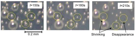
Figure 4.
Shrinking and disappearance of bubbles in the film coating. Yellow circles highlight the bubbles that indicate the shrinking phenomena. It can be seen that the bubbles within the circles have shrunk or disappeared over time.
Figure 5 depicts histograms of the bubble diameter distribution at t = 10 s, 120 s, 180 s, and 240 s. The horizontal axis is the bubble diameter, and the vertical axis is the proportion of bubbles with each diameter to the total number of bubbles. The arithmetic mean diameters D10 of the bubbles are indicated by the solid red lines.
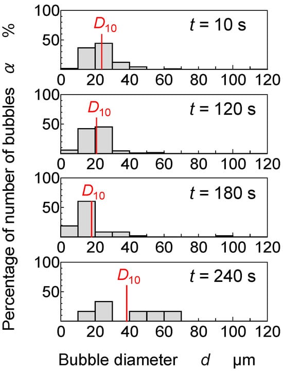
Figure 5.
Bubble diameter distribution and change in arithmetic mean diameter D10.
At t = 10 s, bubbles of various sizes appeared, ranging from less than 5 µm to 50 µm in diameter. Most bubbles at t = 10 s ranged from 10 μm to 30 μm in diameter, with an average diameter D10 of approximately 23.8 μm. At t = 120 s, the histogram shape was almost the same as that at t = 10 s, but the percentage of larger bubbles decreased slightly, while the percentage of smaller bubbles increased. D10 was approximately 20.8 μm. At t = 180 s, the percentage of large bubbles decreased, and the percentage of small bubbles increased further. The peak number of bubbles shifted to the 10–20 μm range, with a D10 of approximately 18.0 μm. At t = 240 s, large bubbles remained, they were sparsely distributed over a wide area, and D10 became 38.4 μm.
From t = 10 s to t = 180 s, the bubble size distribution gradually moved to the smaller side and D10 gradually decreased. One possible reason for this phenomenon is that large bubbles were released early from the surface of the film coating, as bubbles are released easily in the early stages of film coating formation, when the paint viscosity is still low. Since larger bubbles have a greater buoyancy than smaller bubbles, the larger bubbles floated to the surface of the film coating. Consequently, they disappeared from the surface of the film coating before the smaller bubbles and D10 decreased.
D10 shifted to the larger side at t = 240 s. In this stage, the smaller bubbles disappeared after shrinking. By this effect, the overall distribution of the bubble diameter shifted to the larger side. Since the paint viscosity increased over time, the release of bubbles from the film coating surface declined, and the large bubbles were rarely released. At this time, the diameters were sparsely distributed in the range of 10 μm to 70 μm. As explained in Section 3.2, the smaller bubbles shrank and disappeared more quickly, whereas the relatively larger bubbles shrank more slowly; after some time, only the middle-sized bubbles remained.
Dalili et al. reported on the phenomenon of coalescence between bubbles [28]. In particular, they described an increase in the average diameter of the bubbles due to coalescence when the coating thickness was 450 μm. One possible explanation could be that when small bubbles coalesce to form larger bubbles, the surface energy decreases. This may lead to an increase in the bubble diameter. However, in our experiments, we observed very little coalescence of the bubbles within the film coating.
As explained in the section above, the smaller bubbles shrank and disappeared more quickly, while the relatively large bubbles shrank more slowly, as shown in Figure 4. The bubbles in the coating film have higher pressures than the pressure in the surrounding coating film due to the effect of surface tension. The gas inside of the bubble may be dissolved into the surrounding paint through the bubble’s surface. The solubility of gases is proportional to the pressure according to Henry’s law. By this mechanism, it is predicted that the smaller the bubble, the higher the pressure, and the dissolving of gas becomes faster. In the next part, we will make a model and analyze the shrinking phenomenon of bubbles in water-based paints, referring to previous studies on the shrinking phenomenon of microbubbles in water.
3.2. Shrinking Phenomenon of Small Bubbles and Its Theoretical Model
The small bubbles in the film coating exhibited a shrinking phenomenon. The bubbles trapped in the film coating were several tens of micrometers in diameter, as shown in Figure 4. These small bubbles are microbubbles. Microbubble shrinkage occurred because the smaller bubbles had higher internal gas pressures due to the effect of surface tension. Consequently, the gas inside the bubbles dissolved into the liquid. A theoretical model of the small bubbles’ shrinkage and disappearance into the film coating was considered by applying previous research work on microbubbles [35,36,37].
The air bubbles trapped in the film coating are assumed to be air, and the equation of state for an ideal gas is assumed to be applicable. Furthermore, because the bubble diameter changes on the order of a few hundred seconds, the change in the state is assumed to be isothermal. Under these conditions, the derivative of the equation of the state with time yields the following equation:
where V is the bubble volume, n is the total number of molecules in the bubble, and P is the internal pressure of the bubble. If the bubble is spherical and its radius is r, then the time variation of r can be obtained from the following differential equation [35]:
where the time derivative dn/dt represents the rate of change of the molecules in the bubble and is related to the dissolution of gas into the paint through the bubble’s interface. The dissolution of gas can be treated as a mass transfer phenomenon due to concentration differences and is described by Equation (3) [36,37].
where is the number of molecules of chemical species i, is the diffusion coefficient of chemical species i, is the saturated concentration of chemical species i at the interface, and is the concentration of chemical species i in the paint far from the bubble.
Here, we assume that the gas component in the bubble is air and composed of oxygen (O2) and nitrogen (N2) in mole fractions of 21% and 79%, respectively. The fractions of O2 and N2 in the bubble are not constant because the rates of O2 and N2 dissolution into the paint are different, but for the simplicity of the theory, they are assumed to be constant here. Under these assumptions, Equation (3) can be rewritten as follows:
where and are the diffusion coefficients of O2 and N2, respectively; and are the saturated concentrations of O2 and N2, respectively; and and are the concentrations of O2 and N2 in the paint far from the bubble, respectively.
The dissolution of gases in paints has been insufficiently studied, and detailed information about paint components has not been published. Water-based paints come in two types, namely, dissolved paints that use water-soluble resins and paints in which the resin is emulsified for dispersion in water. In both cases, conventional thinners have been replaced with water as the diluent. Therefore, paints contain large amounts of water. The water-based paint used in this study was diluted by adding water (for viscosity adjustment) and a small amount of a solidifier. We consider that the gas in the bubble mainly dissolves in the water of the water-based paint, and we use data from previous studies on the shrinking of microbubbles in water.
The diffusion coefficients and are set to 2.50 × 10⁻⁹ m2/s and 1.90 × 10⁻⁹ m2/s, respectively [35]. The concentrations of O2 and N2 on the bubble’s surface, and , respectively, are calculated using Henry’s law as follows [35,36]:
where is the liquid density; and are Henry’s law constants; is the molecular weight of H2O (=18 g/mol); P is the bubble’s internal pressure; and and are the molar ratios of O2 and N2, respectively, and are defined as follows:
where and are the instantaneous mole numbers of O2 and N2, respectively. The Henry’s law constants and are calculated using the following equations [35,36]:
Far from the bubble, the same type of equation as Equations (5) and (6) holds.
where is the saturated pressure far from the bubble. We also assume here that the molar ratios of O2 and N2 are the same as those on the bubble’s surface.
The pressure P in Equations (2), (5) and (6) is given by the following Young–Laplace equation:
where σ is the surface tension of the paint. By substituting Equations (5), (6) and (11)–(13) into Equation (4) and rearranging them, we derive the derivative dn/dt in Equation (2). Finally, by substituting Equation (13) into dP/dt in Equation (2), we obtain the following equation for the bubble’s radius:
where R and T are the universal gas constant and temperature, respectively, and they come from the equation of state. This equation is integrated, yielding the following equation:
where C is the integral constant, and we need to decide on the initial condition. As for the initial conditions, we set r0 as the initial bubble radius. Then, Equation (15) is rewritten as follows:
This equation is difficult to solve explicitly for r, but it represents the relationship between the bubble’s radius and time. The bubble’s lifetime tL is derived from Equation (16) as follows by setting the bubble radius to zero:
Figure 6 shows the change in the bubble’s radius with the initial bubble radius. The circles indicate the experimental data. The solid lines indicate the values that were theoretically derived using Equation (16). The surface tension of the paint was measured using a du Noüy ring tensiometer (Model D, Ito Seisakusho Co., Ltd., Chuo-ku, Japan). The surface tension σ value used in Equation (16) is 36.3 × 10⁻³ N/m. The figure shows that the theoretical curves were roughly consistent with the experiment data. The bubble-shrinking phenomenon was theoretically represented. These results suggest that the time required for the bubbles to disappear dependeds highly on the initial bubble radius.
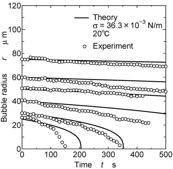
Figure 6.
Shrinking of bubbles in film coating.
Figure 7 shows the relation between the initial bubble radius and the bubble’s lifetime. The solid line is the theoretical curve for the test paint, calculated using the measurement data of the surface tension. The white circles are the obtained experimental data. The dashed line is a theoretical curve calculated using the surface tension of water (72.8 × 10⁻³ N/m). The bubbles had longer lifetimes in the paint because its surface tension was lower (36.3 × 10⁻³ N/m) than that of water. The results of previous studies for water are denoted by the black symbols. The theoretical study of Yasui et al. accurately accounted for changes in the fractions of O2 and N2 for submicron bubbles [36]. The experimental studies by Tanaka et al. [38] and Iwakiri et al. [39] also took into account the saturation level of air in water. Each piece of data on the changes in the bubble diameter under saturated conditions was obtained from figures in their papers. The data of these previous studies were consistent with the theoretical curves obtained in this study. Therefore, Equation (17) could predict the bubble lifetime until the small bubbles disappeared.
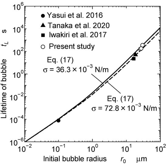
Figure 7.
Relation between initial bubble radius and bubble lifetime [36,38,39].
3.3. Discussion
Because of the defects caused by air bubbles on a coating surface, air bubbles should be removed from the coating surface as quickly as possible. Air bubbles that are several hundred microns in size are generally released out of the film coating in the early stages of film coating formation. On the contrary, as shown in this study, small bubbles gradually dissolve and disappear. However, as the diluent evaporates from the paint film surface and begins to solidify, bubbles of a certain size remain. Furthermore, during heated drying, these residual bubbles grow and become defects. Figure 8 shows a photograph of a heat-dried film coating surface. The remaining bubbles in the film coating grew and created large defects.
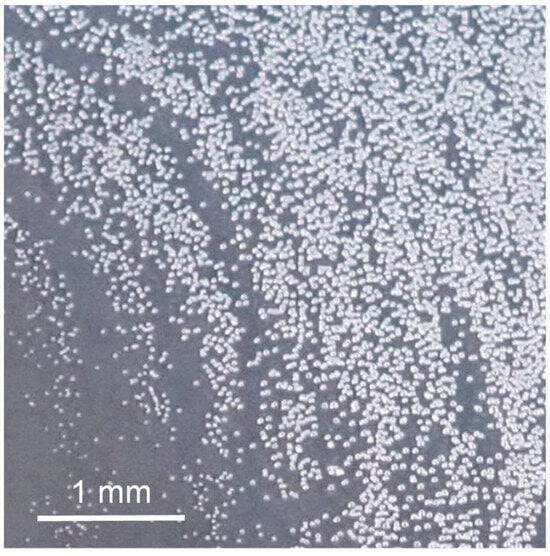
Figure 8.
Coating defect caused by bubbles remaining after heating of coated surface.
Now, we consider the time tS at which the coated surface dries and the surface begins to solidify. This time may be predicted as the evaporation of the diluent from the film coating surface. The time at which heating and drying begin can also be taken as tS. In any case, if the lifetime related to the initial diameter of the bubbles trapped in the film coating satisfies tL > tS, then the bubbles will cause coating defects. Therefore, the disappearance behaviors of bubbles trapped in the film coating surface should be predicted to avoid their induced defects. In this study, we presented a model that predicts the lifetimes of bubbles until their disappearances.
4. Conclusions
The behaviors of bubbles trapped in a film coating during spray coating were investigated experimentally and theoretically to elucidate the formation processes of bubbling defects. Through the visualization of a film coating, the shrinking and disappearance of small bubbles were observed. With the use of previous studies about microbubble dynamics, a theoretical model of bubble shrinking was developed based on the Young–Laplace equation of a bubble’s inner pressure and Henry’s law for bubble gas dissolution into the film coating. The lifetime of a bubble in the film coating was predicted using this simple theoretical model.
Author Contributions
Conceptualization, A.Y. and K.A.; formal analysis, K.A.; investigation, R.N. and A.Y.; methodology, R.N., A.Y. and K.A.; project administration, K.A.; supervision, K.A.; visualization, R.N. and A.Y.; writing—original draft, R.N. and A.Y.; writing—review and editing, K.A. All authors have read and agreed to the published version of the manuscript.
Funding
This research received no external funding.
Institutional Review Board Statement
Not applicable.
Informed Consent Statement
Not applicable.
Data Availability Statement
Not applicable.
Acknowledgments
The authors acknowledge Shota Oosaka and Shota Watanuki for their support in the experiments.
Conflicts of Interest
The authors declare no conflict of interest.
References
- Akafuah, N.K.; Poozesh, S.; Salaimeh, A.; Patrick, G.; Lawler, K.; Saito, K. Evolution of the automotive body coating process—A review. Coatings 2016, 6, 24. [Google Scholar] [CrossRef]
- Pendar, M.-R.; Páscoa, J.C. Numerical modeling of electrostatic spray painting transfer processes in rotary bell cup for automotive painting. Int. J. Heat Fluid Flow 2019, 80, 108499. [Google Scholar] [CrossRef]
- Cho, D.-Y.; Swan, S.; Kim, D.; Cha, J.-H.; Ruy, W.-S.; Choi, H.-S.; Kim, T.S. Development of paint area estimation software for ship compartments and structures. Int. J. Nav. Archit. Ocean Eng. 2016, 8, 198–208. [Google Scholar] [CrossRef][Green Version]
- Xu, P.; He, J.; Liao, L.; Gong, J.; Zhao, S.; Xu, K. Experimental design and spray technology research of ship paint spraying robot. IOP Conf. Ser. Mater. Sci. Eng. 2019, 612, 032067. [Google Scholar] [CrossRef]
- Zhao, L.; Liu, J.; Yin, Y.; Pei, J.; Xiao, W.; Zhang, H.; Wei, S. Field investigation of pollutant characteristics and targeted ventilation control strategies in high-ceiling aircraft spraying workshop. Process Saf. Environ. Prot. 2022, 159, 627–639. [Google Scholar] [CrossRef]
- Maury, P.; Quemper, J.-M.; Pocas, S.; Van Vliet, D.; Noordam, N.; ten Berge, P.; Best, K. Sub-micron imaging on high-topography wafers using spray coating and projection lithography. Microelectron. Eng. 2010, 87, 904–906. [Google Scholar] [CrossRef]
- Keller, S.S.; Bosco, F.G.; Boisen, A. Ferromagnetic shadow mask for spray coating of polymer patterns. Microelectron. Eng. 2013, 110, 427–431. [Google Scholar] [CrossRef]
- Lee, J.-H.; Sagawa, T.; Yoshikawa, S. Thickness dependence of photovoltaic performance of additional spray coated solar cells. Thin Solid Film. 2013, 529, 464–469. [Google Scholar] [CrossRef]
- Dinh, T.-V.; In-Young Choi, Y.S.S.; Song, K.-Y.; Sunwoo, Y.; Kim, J.-C. Volatile organic compounds (VOCs) in surface coating materials: Their compositions and potential as an alternative fuel. J. Environ. Manag. 2016, 168, 157–164. [Google Scholar] [CrossRef]
- Yadav, R.; Pandey, P. A review on volatile organic compounds (VOCs) as environmental pollutants: Fate and distribution. Int. J. Plant Environ. 2018, 4, 14–26. [Google Scholar]
- Mo, Z.; Lu, S.; Shao, M. Volatile organic compound (VOC) emissions and health risk assessment in paint and coatings industry in the Yangtze River Delta, China. Environ. Pollut. 2021, 269, 115740. [Google Scholar] [CrossRef] [PubMed]
- Wang, D.; Li, X.; Zhang, X.; Zhao, W.; Zhang, W.; Wu, S.; Shao, X.; Nie, L. Spatial distribution of health risks for residents located close to solvent-consuming industrial VOC emission sources. J. Environ. Sci. China 2021, 107, 38–48. [Google Scholar] [CrossRef] [PubMed]
- Xue, J.; Cai, H.; Li, W.; Pei, Y.; Guan, H.; Guo, Z.; Wu, C.; Qu, C.; Li, W.; Liu, J. Emissions of VOCs and SVOCs from polyvinyl chloride building materials: Contribution to indoor odor and inhalation health risks. Build. Environ. 2023, 229, 109958. [Google Scholar] [CrossRef]
- Mosallaei, S.; Hashemi, H.; Hoseini, M.; Dehghani, M.; Naz, A. Polycyclic Aromatic Hydrocarbons (PAHs) in household dust: The association between PAHs, Cancer Risk and Sick Building Syndrome. Build. Environ. 2023, 229, 109966. [Google Scholar] [CrossRef]
- Kim, B.R. VOC emissions from automotive painting and their control: A review. Environ. Eng. Res. 2011, 16, 1–9. [Google Scholar] [CrossRef]
- Liu, F.; Zhang, T.T.; Zhang, H.; Huo, Q.; Wang, J.; Long, Z.; Liu, J. Removing painting-generated VOCs in a commercial airplane hangar with multiple portable exhaust hoods. Build. Environ. 2021, 196, 107797. [Google Scholar] [CrossRef]
- Qi, Y.; Shen, L.; Zhang, J.; Yao, J.; Lu, R.; Miyakoshi, T. Species and release characteristics of VOCs in furniture coating process. Environ. Pollut. 2019, 245, 810–819. [Google Scholar] [CrossRef]
- Simion, A.I.; Ionita, I.; Grigoras, C.-G.; Favier-Teodorescu, L.G.; Gavrila, L. Development and optimization of water based paint formula in order to reduce VOCs emissions. Environ. Eng. Manag. J. 2015, 14, 277–288. [Google Scholar] [CrossRef]
- Suzuki, N.; Nakaoka, H.; Hanazato, M.; Nakayama, Y.; Takaya, K.; Mori, C. Emission rates of substances from low-volatile-organic-compound paints. Int. J. Environ. Sci. Technol. 2019, 16, 4543–4550. [Google Scholar] [CrossRef]
- Sato, Y.; Shimada, T.; Abe, K.; Inomata, H.; Kawasaki, S.-I. Development of a solvent selection guide for CO2 spray coating. J. Supercrit. Fluids 2017, 130, 172–175. [Google Scholar] [CrossRef]
- Kawasaki, S.-I.; Sakurai, Y.; Fujii, T. Study on atomization mechanism in spray coating of organic paint mixed with high-pressure carbon dioxide as a diluting solvent. J. Supercrit. Fluids 2022, 179, 105408. [Google Scholar] [CrossRef]
- Schoff, C.K. Surface defects: Diagnosis and cure. J. Coat. Technol. 1999, 71, 57–73. [Google Scholar] [CrossRef]
- Torkar, M.; Godec, M. Surface defects in car paint from recombination of atomic hydrogen. Eng. Fail. Anal. 2003, 10, 325–328. [Google Scholar] [CrossRef]
- Taherimakhsousi, N.; MacLeod, B.P.; Parlane, F.G.L.; Morrissey, T.D.; Booker, E.P.; Dettelbach, K.E.; Berlinguette, C.P. Quantifying defects in thin films using machine vision. NPJ Comp. Mater. 2020, 6, 111. [Google Scholar] [CrossRef]
- Moradi, N.; Gorji Kandi, S.; Yahyaei, H. A new approach for detecting and grading blistering defect of coatings using a machine vision system. Measurement 2022, 203, 111954. [Google Scholar] [CrossRef]
- Domnick, J.; Gruseck, D.; Pulli, K.; Scheibe, A.; Ye, Q.; Brinckmann, F. Investigations of the drying process of a water based paint film for automotive applications. Chem. Eng. Process. Process Intensif. 2011, 50, 495–502. [Google Scholar] [CrossRef]
- Evans, P.L.; Schwartz, L.W.; Roy, R.V. A mathematical model for crater defect formation in a drying paint layer. J. Colloid Interface Sci. 2000, 227, 191–205. [Google Scholar] [CrossRef]
- Dalili, A.; Chandra, S.; Mostaghimi, J.; Fan, H.T.C.; Simmer, J.C. Bubble entrapment and escape from sprayed paint films. Prog. Org. Coat. 2016, 97, 153–165. [Google Scholar] [CrossRef]
- Saranjam, N.; Chandra, S. Bubble growth and movement in drying paint films. Chem. Eng. Sci. 2016, 145, 149–161. [Google Scholar] [CrossRef]
- Sanada, T.; Watanabe, M.; Fukano, T. Effects of viscosity on coalescence of a bubble upon impact with a free surface. Chem. Eng. Sci. 2005, 60, 5372–5384. [Google Scholar] [CrossRef]
- Lhuissier, H.; Villermaux, E. Bursting bubble aerosols. J. Fluid Mech. 2012, 696, 5–44. [Google Scholar] [CrossRef]
- Kadoura, M.; Saranjam, N.; Chandra, S.; Fan, H. Nucleation of bubbles during drying of sprayed paint films. Prog. Org. Coat. 2016, 99, 452–462. [Google Scholar] [CrossRef]
- Yano, A.; Oe, T.; Takaishi, K.; Amagai, K. Visualization of the paint film formation process during spray coating. Adv. Exp. Mech. 2019, 4, 43–48. [Google Scholar]
- Yano, A.; Hamada, K.; Amagai, K. Evaluation of coating film formation process using the fluorescence method. Coatings 2021, 11, 1076. [Google Scholar] [CrossRef]
- Fan, W.; Li, Y.; Lyu, T.; Yu, J.; Chen, Z.; Jarvis, P.; Huo, Y.; Xiao, D.; Huo, M. A modeling approach to explore the optimum bubble size for micro-nanobubble aeration. Water Res. 2023, 228, 119360. [Google Scholar] [CrossRef] [PubMed]
- Yasui, K.; Tuziuti, T.; Kanematsu, W. Extreme conditions in a dissolving air nanobubble. Phys. Rev. E 2016, 94, 013106. [Google Scholar] [CrossRef]
- Yasui, K.; Tuziuti, T.; Kanematsu, W. High temperature and pressure inside a dissolving oxygen nanobubble. Ultrason. Sonochem. 2019, 55, 308–312. [Google Scholar] [CrossRef]
- Tanaka, S.; Kastens, S.; Fujioka, S.; Schlüter, M.; Terasaka, K. Mass transfer from freely rising microbubbles in aqueous solutions of surfactant or salt. Chem. Eng. J. 2020, 387, 121246. [Google Scholar] [CrossRef]
- Iwakiri, M.; Terasaka, K.; Fujioka, S.; Schluter, M.; Kastens, S.; Tanaka, S. Mass transfer from a shrinking single microbubble raising in water. Jpn. J. Multiph. Flow 2017, 30, 529–535. [Google Scholar] [CrossRef][Green Version]
Disclaimer/Publisher’s Note: The statements, opinions and data contained in all publications are solely those of the individual author(s) and contributor(s) and not of MDPI and/or the editor(s). MDPI and/or the editor(s) disclaim responsibility for any injury to people or property resulting from any ideas, methods, instructions or products referred to in the content. |
© 2023 by the authors. Licensee MDPI, Basel, Switzerland. This article is an open access article distributed under the terms and conditions of the Creative Commons Attribution (CC BY) license (https://creativecommons.org/licenses/by/4.0/).