Article

Corrosion and Tribological Performance of Diamond-like Carbon-Coated ZK 60 Magnesium Alloy

by
Adrián Claver
1,
Iván Fernández
2,
José Antonio Santiago
2,
Pablo Díaz-Rodríguez
2,
Miguel Panizo-Laiz
3,4,
Joseba Esparza
5,
José F. Palacio
1,5,
Gonzalo G. Fuentes
1,5,
Iñaki Zalakain
1 and
José Antonio García
1,*
1
Institute for Advanced Materials and Mathematics (INAMAT2), Campus de Arrosadia, Universidad Pública de Navarra (UPNA), 31006 Pamplona, Spain
2
Nano4Energy, C. de José Gutiérrez Abascal, 2, 28006 Madrid, Spain
3
Centro Láser, Universidad Politécnica de Madrid, Alan Turing 1, 28031 Madrid, Spain
4
Departamento de Física Aplicada e Ingeniería de Materiales, Escuela Técnica Superior de Ingenieros Industriales de Madrid, UPM, Calle José Gutiérrez Abascal, 2, 28006 Madrid, Spain
5
Centre of Advanced Surface Engineering, AIN, 31191 Cordovilla, Spain
*
Author to whom correspondence should be addressed.
Coatings 2023, 13(11), 1871; https://doi.org/10.3390/coatings13111871
Submission received: 29 September 2023 / Revised: 26 October 2023 / Accepted: 30 October 2023 / Published: 31 October 2023

Abstract

:
In this work, hydrogenated and hydrogen-free Diamond-Like Carbon (DLC) coatings were deposited into ZK60 magnesium alloy using the promising coating method High-Power Impulse Magnetron Sputtering (HiPIMS). CrC and WC were used as interlayers of the thin films, and their influence was studied. The structure and composition of the coatings were characterized using scanning electron microscopy (SEM), energy-dispersive X-ray spectroscopy (EDS), and Raman spectroscopy. Tribological tests, scratch tests, and nanoindentation were performed to obtain information about the mechanical and tribological properties of the coatings. Finally, immersion and electrochemical tests were performed to evaluate the corrosion behavior of the samples. The results showed a homogeneous layer with improved wear resistance, toughness, and hardness in addition to good adhesion to the substrate of the ZK60 magnesium alloy. The hydrogenated DLC coating showed better results that the hydrogen-free thin layer, and relevant differences were observed depending on the interlayer. In this work, the improvement in the tribological and corrosive properties of Mg alloys was studied by using thin layers of DLC and different intermediate layers, achieving similar or even better wear and adhesion values than with thicker layers.

1. Introduction

Magnesium alloys have attracted great interest recently due to their potential application in different industries such as biomedicine, automotive, or aeronautics [1,2]. The combination of their good mechanical properties, biocompatibility, and low density gives them an advantage over other materials in terms of weight savings, resource availability, and sustainability [3,4]. However, magnesium alloys present several issues that limit their real applicability for the time being, such as rapid and uncontrollable corrosion and poor fatigue resistance [5,6,7,8].
To address this problem, over the last few years, different studies have focused on studying the properties of these alloys, aiming to attain a better understanding of their wear and corrosion mechanisms. Nevertheless, the implementation of these alloys in certain applications still requires major study and development of their functionalization to suit the demands of the industry.
As an example, in biomedicine-related applications, the design and development of surface protection strategies are mandatory requirements that must be fulfilled to ensure the proper functioning of magnesium alloys [9,10]. In addition to their high biocompatibility and biodegradability, the aforementioned mechanical properties are similar to bone, so the stress shielding issue observed with other biomaterials, such as titanium or stainless steel, can be avoided [4,5]. One of the main advantages of biodegradable materials such as magnesium is the possibility of designing temporary biodegradable implants that avoid the need for second surgical procedures to remove the implant after the healing of the surgical specimen. This is because the degradation of these parts occurs gradually within the organism throughout the bone healing process, minimizing health risks and economic costs [11].
For applications such as automotive or aerospace, magnesium and its alloys have been postulated as an alternative to lighten components, driven by an increasing demand for electric vehicles and leading to the emergence of new magnesium alloys [12]. However, the main drawback of these materials consists of their low corrosion and fatigue resistance, derived from their low hardness and toughness. Therefore, they do not meet the requirements and regulations for the automotive industry, and their industrial implementation is strongly limited. However, their functionalization and corresponding improvement in properties (such as mechanical and surface properties) have allowed their use in certain applications under more demanding conditions where fatigue, corrosion, or tribocorrosion problems are still present.
Over the last few years, different strategies have been studied to improve the corrosion resistance and mechanical properties of Mg alloys, such as alloying with other elements [13], micro-arc oxidation [14], physical vapor deposition (PVD) [12], sol-gel methods [15], or chemical surface treatments [16]. Coatings have proved themselves to be an effective strategy to protect Mg alloys in severely corrosive environments, but most of them present high friction coefficients without lubricity, leading to poor wear resistance in sliding conditions [17]. Among the coating methods used, PVD processes are regarded as a promising technology, as it allows the synthesis of a vast variety of coatings, thus improving wear resistance, mechanical properties (hardness, toughness, resistance to plastic deformation, etc.), or corrosion resistance, among others. However, it must be considered that porosity, pinholes, or cracks produced during the deposition of PVD coatings on magnesium alloys will facilitate the penetration of any corrosive solution through the grown film [18,19].
Within the PVD-deposited materials available, Diamond-Like Carbon (DLC) coatings are part of the so-called amorphous carbon coatings with exceptional chemical and mechanical properties that make them ideal candidates for different industrial applications [20,21] including cutting and forming tools [22], medical devices [23], or automotive industry [24]. The DLC family of coatings covers a wide range of amorphous carbon coatings that combine the structure of diamond and graphite in an amorphous network of carbon atoms in sp2 covalent hybridization (low friction and electrical conductivity properties of graphite) and sp3 hybridization (hardness properties of diamond) [25,26]. The most representative properties of these coatings: high hardness, low friction, great wear resistance, and chemical inertness [20,21,26], depend on the relationship between the amount of sp2 and sp3 bonds. However, the difference in mechanical properties (hardness and stiffness) between the DLC layer and the Mg substrate can lead to adhesion problems due to the limited bearing capacity between the layers, as the high residual stress at the substrate-coating interface can result in low bond strength [27]. Different studies are dealing with this issue by improving the adhesion of DLC layers with Mg substrates using strategies such as doping with different elements [28,29], depositing transition layers [30] that reduce internal stresses, or performing pretreatments prior to deposition [31,32]. The use of transition layers has led to improvements in terms of adhesion, but the use of these metallic layers presents the risk of suffering from galvanic corrosion. The metals traditionally used (Al, Ti, Cr, etc.) have more positive potentials than Mg, so if the corrosive medium penetrates through the coating, degradation would be accelerated because of microgalvanic corrosion-driven processes [30,33]. Wu et al. reported that it was indeed possible to improve the adhesion between a coating and substrate in DLC/magnesium alloy systems using Cr and CrN interlayers, but corrosion resistance was not enhanced [34]. Similar results were obtained by Dai et al. using Cr-incorporated diamond-like carbon (Cr-DLC) films on AZ31 magnesium alloy, which improved the adhesion but not the corrosion resistance [29]. On the other hand, Masami et al. deposited DLC and Si-DLC coatings with Ti interlayers to improve adhesion, and although this coating served its purpose, it also presented corrosion problems [35]. Therefore, the use of interlayers or doping the DLC layers seems to be insufficient to achieve coatings with both improved adhesion and enhanced properties.
Several studies have analyzed different PVD techniques in order to tackle the problems encountered when coating Mg alloys: DC magnetron sputtering [12], radio frequency magnetron sputtering [36], cathodic arc physical vapor deposition [37], or High-Power Impulse Magnetron Sputtering (HiPIMS) [38,39]. Among them, HiPIMS technology has shown the best performance in terms of mechanical properties and corrosion resistance when depositing ceramic coatings on Mg alloys. The HiPIMS technique allows the generation of highly energetic ions from the target material with the application of high-energy pulses in a short time and a low-duty cycle, resulting in denser and smoother coatings with enhanced adhesion and mechanical properties, highlighting hardness and toughness [40,41,42]. Although the generation of defects in the case of HiPIMS follows a similar trend as other PVD techniques, such as DC, the microstructure of the coating achieved, as well as its wettability properties, leads to better corrosion resistance and higher hardness values. On the other hand, although the defects are distributed in a similar way, in the coatings achieved using HiPIMS, they are quickly neutralized by corrosion effects, inhibiting the severe corrosion character of this coating compared with DC. Despite the improvements already mentioned, the literature related to this technology applied to Mg alloys is scarce. Therefore, it is necessary to continue studying it in detail and optimize the coatings proposed to suit all the requirements demanded for each application, thus allowing the implementation of these alloys.
In the present work, a-C and a-C:H DLC coatings were deposited on ZK60 magnesium alloy substrates using HiPIMS in order to improve their wear, corrosion, and mechanical properties. Depositing DLC layers on Mg is very difficult due to the differences in their mechanical properties; moreover, by increasing the thickness of the layers, the adhesion can be compromised. Therefore, in this study, we tried to use HiPIMS to successfully deposit thin DLC films that ensure good adhesion with the soft Mg substrate, maintaining and even improving the mechanical properties and wear resistance that would present thicker layers. Cr, CrC, and WC were used as interlayers to improve adhesion between the DLC layers and the substrate, and the behavior of both coatings in terms of wear resistance, corrosion resistance, and mechanical properties was analyzed.

2. Materials and Methods

2.1. Reference Substrate

ZK60A-T5 commercial magnesium alloy (TeknoSteel, Rome, Italy) was chosen due to its biocompatibility, non-toxicity, and good mechanical properties (superior strength and ductility) [43]. The main elements of this alloy make it an ideal choice for biomedical applications. Zn presents benefits for carrying out bone remodeling and is essential in the human body [44], while Zr, in addition to having a grain-refining effect on magnesium alloys, is less toxic to cells [45]. Flat and round samples with a thickness of 5 mm were obtained from 50- and 75-diameter bars. Information on the chemical composition and mechanical properties according to ASTM B107/B107M-13 that were provided by the manufacturer is presented in Table 1.
The surface condition of the reference substrate prior to the deposition process is critical to achieve good adhesion between the coating and the substrate and, therefore, to attain better mechanical and corrosion properties. Consequently, a sample surface conditioning process was implemented, consisting of grounding, polishing, and cleaning (Table 2).
In this way, it was possible to achieve surface roughness values of less than 0.10 ± 0.02 µm in all the samples before the deposition processes.

2.2. Film Deposition Technique

The coating of the samples was carried out in the industrial system xPro4C designed by PVT GmbH. It integrates in a vacuum chamber of 0.51 m3 (680 × 650 × 1150 mm) four cathodes designed with adjustable magnetic field configurations. The plasma volume is 350 × 650 mm (Ø × H). Figure 1 outlines schematically a view of the chamber cross-section. A scheme of the structure of each coating is shown in Figure 2.
The chamber is evacuated with two turbomolecular pumps and two double-stage rotary vane pumps. The four cathodes are incorporated in equidistance. For DLC coating deposition, two of the cathodes are operated as unbalanced magnetrons (UBMs) carrying graphite targets and powered with DC-pulsed and HiPIMS power supplies. The third cathode is used for depositing a WC interlayer with a balanced magnetron configuration carrying a binder-free WC target. The fourth cathode is operated in HiPIMS mode carrying a Cr target.
The parameters used for the different substrate pretreatment as well as for the deposition of the metal bonding interlayers and DLC coatings are briefly described in the following Table 3.

2.3. Thickness, Structural Properties, and Profile Composition

The thickness of the samples was measured with a calotest using a CSM Calotest device (CSM Instruments, Needham, MA, USA) with a 30 mm diameter stainless-steel ball and superfine (0.25 μm) diamond water suspension as the abrasive medium.
The structural properties of the prepared DLC coatings were analyzed using a Raman micro-spectroscopy system. A Renishaw PLC spectrometer was used to record the Raman spectra, focusing a 10 mW Ar ion laser working at a line of 532 nm on the surface of the coatings. Two Gaussian functions were used to curve-fetter the obtained Raman spectrum, peaking at disordered (D-band) and graphite (G-band) modes.
Finally, in order to obtain information about the layer structure, microscopy images were obtained using an S4800 Field Emission SEM microscope (HITACHI, Tokyo, Japan).

2.4. Mechanical and Tribological Tests

The roughness of the samples was evaluated before and after the deposition process to ensure the maintenance of the surface finish and roughness. A Smart confocal microscope (Sensofar, Barcelona, Spain) fitted with a 20× objective was used to measure the arithmetical mean height value (Sa) of each sample. The measurements were performed in triplicate on each sample to guarantee repeatability, and the following filters were used according to ISO 25178 standard [46]:
  • Standard cut-off of the high-pass filter: λs = 2.50 µm.
  • Standard cut-off of the low-pass filter: λc = 0.25 mm.
The adhesion assessment between the substrate and coatings was carried out with a CSM REVETEST Scratch tester fitted with a diamond Rockwell indenter with a tip radius of 200 μm. The test parameters that were used were a load rate of 100 N/min, a final load of 100 N, a speed of 10 mm/min, and a total test length of 10 mm. Using adhesion tests, it is possible to record signals of penetration of the indenter within the substrate, acoustic emission, and the coefficient of friction. These signals were combined with images obtained with optical microscopy to define the spots where different events occur. Analyzing this information, it is possible to define three different critical loads (LCs).
  • First critical load (Lc1): The appearance of the first cohesive failure. Determined by plastic deformation failures, cracking for conformal type, laterals, or tensile ones, among others.
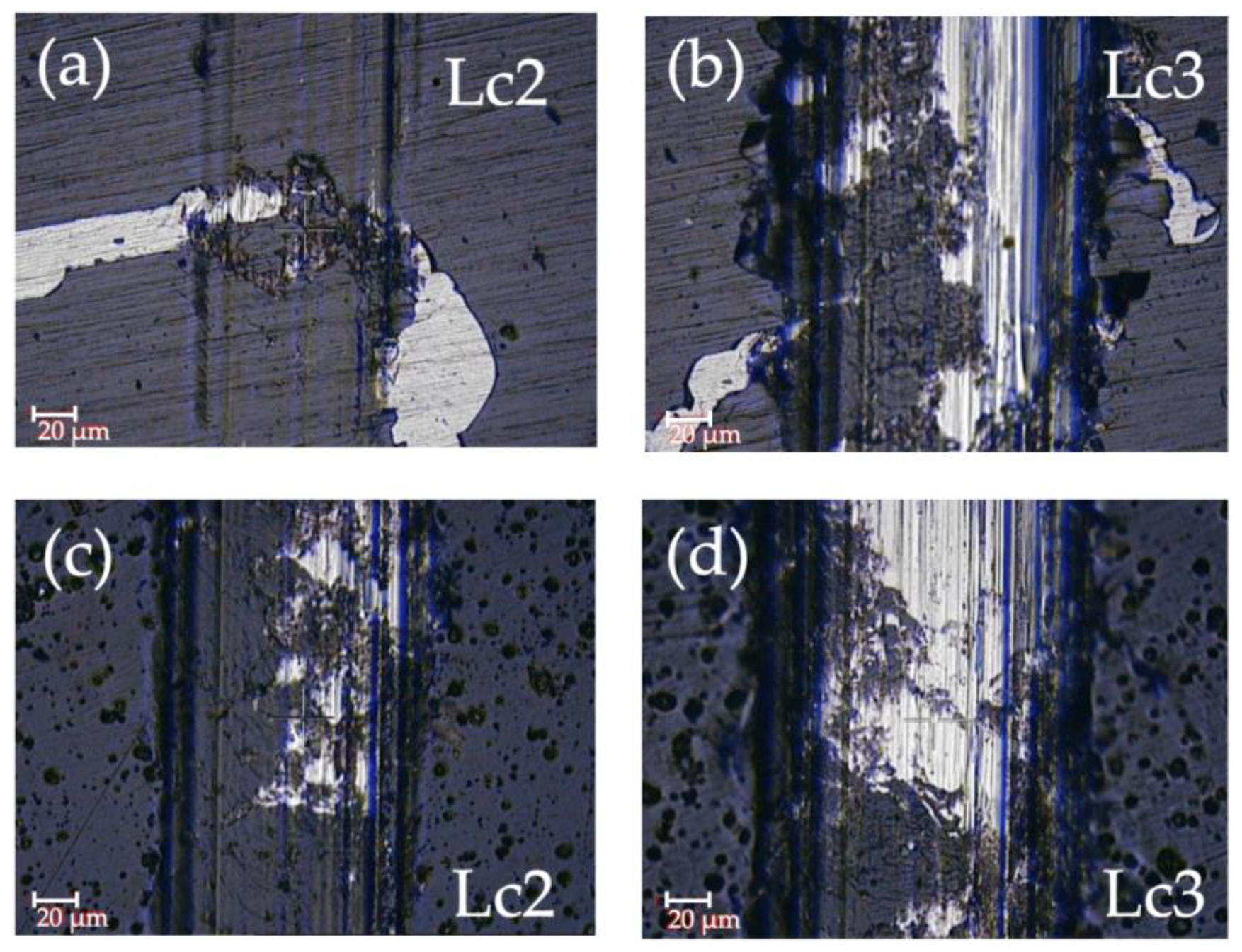
  • Second critical load (Lc2): The appearance of the first adhesive failure. Determined by delamination failures, frontal deformation cracking, superficial lifts, lateral chipping, etc.
  • Third critical load (Lc3): At least 50% delamination of the coating or the appearance of a critical defect.
Nanoindentation tests were performed with a Nanoindentation Tester TTX-NHT3 (Anton Paar) fitted with a Berkovich tip. Different testing parameters were used to evaluate the influence of the substrate and corroborate the thickness measurements performed with a calotest. Four different maximum load values were selected: 1, 5, 10, and 25 mN, and the load/unloading rate that was used in all cases was 6 times the value of the maximum load, i.e., 6, 30, 60, and 150 mN/min, respectively. In this way, it was possible to evaluate the evolution of the measured H and E values as a function of the penetration of the indenter. Finally, hardness and Young’s modulus values were obtained using the Oliver and Pharr method for the tests carried out with 1 mN of maximum load [47].
Tribomechanical tests were performed using Microtest MT series equipment (Microtest S.A.) with a pin-on-disk configuration using 6 mm alumina balls (Ramax = 0.050 μm and hardness of around 1650 HV) as the counterpart. Uncoated and coated samples were used as the disks, and three different test conditions were used to characterize the performance of the coatings in different requirements. The test parameters are defined in Table 4.
The friction coefficient was directly obtained from the tribological tests, while the wear coefficient was evaluated using confocal microscopy to measure the volume loss in the wear track. Volume loss was analyzed in three different zones of each wear track, and then it was extrapolated to the whole track using expression (1). Finally, the wear coefficient was calculated using the expression defined in ASTM G99 [48].
V total _ loss   ( m 3 ) = 2 × Π × Test   radius × V l o s s _ m e a s u r e d Focused   zone   length

2.5. Corrosion Tests

Electrochemical measurements were performed to evaluate the corrosion resistance of the samples. An Autolab Potentiostat/Galvanostat PGSTAT302N (Metrohm, Herisau, Switzerland) with a three-electrode cell system was used to carry out the tests. The electrode selection was as follows:
  • Working electrode: test materials with an exposed area of 13.85 cm2.
  • Reference electrode: silver/silver chloride (Ag/AgCl 3 M) electrode.
  • Counter electrode: platinum electrode.
Potentiodynamic polarization tests (PDP) were performed at room temperature and using sodium chloride NaCl (1 M) as an electrolyte. First, the samples were immersed in NaCl for 15 min to stabilize the system and ensure a stable open circuit potential (OCP). Subsequently, the polarization of the system was made at a range of ±250 mV and a scanning rate of 1 mV/s. Finally, Ecorr and icorr were determined using the Tafel extrapolation method from the PDP plots.
In addition to PDP tests, the in vitro corrosion behavior of the samples was also evaluated with immersion degradation tests in NaCl. By observing the corrosion reaction and potential of magnesium expressed in (2), it is possible to determine that the evolution of 1 mol of hydrogen gas corresponds to the dissolution of 1 mol of Mg. Therefore, it is possible to evaluate the mass loss of Mg by measuring the produced volume of H2 gas [49,50].
Mg + 2H2O = Mg2+ + 2(OH) + H2
An experimental setup consisting of a graduated inverted burette placed in a corrosion cell was used to collect the H2 gas generated during immersion. The initial plan for these tests was to immerse uncoated and coated samples in 60 mL NaCl for 4 days at room temperature and monitor H2 evolution and mass change. For that purpose, samples were masked to leave only an exposed surface area of 3 cm2. However, due to the fast and unexpected degradation of the samples during immersion, the tests were stopped after the first 24 h, and the sample surface and the generated corrosion products were evaluated using SEM-EDX. Therefore, no results regarding H2 evolution or mass change are reported in this work.

3. Results

3.1. Thickness, Structural Properties, and Profile Composition

For all samples, characteristic D and G bands of carbon were identified (by fitting the Raman spectra using two Gaussian functions) around 1340 cm−1 and 1540 cm−1 (Figure 3). All Raman spectra of the films exhibit broadening and overlapping of the two bands, indicating a disordered amorphous carbon structure [51].
In the case of hydrogenated amorphous carbon (a-C:H), a higher intensity of the Raman signal is attributed to the photoluminescence (PL) effect [52]. This effect is driven by the progressive saturation of carbon dangling bonds with higher hydrogen content. Thus, they incorporate C-H sp2 bonds, and this can be clearly observed in the higher signal of the Raman analysis and the more pronounced G-peak.
For amorphous carbon coatings, the signal is reduced, and the width at peak G increases. The FWHM (G) has been reported to increase with the disorder of the films, with ordered materials dominated by aromatic rings, such as graphite, having reduced values [26]. In addition to increasing the Raman signal, the C-H sp2 bonds that are present in the a-C:H samples ultimately also facilitate the formation of graphitic tribolayers during tribological testing, resulting in reduced COF and wear rate values. However, the graphitic content of both coatings cannot be directly compared, as the amount of sp2 C-C and C-H bonds in the coatings is different.
After tribological tests, the carbon structure identified using the Raman analysis shows a similar trend. The carbon structure is preserved, and the spectra is very similar to the spectra obtained before testing. In the case of the a-C coating in tests 1 and 2, the thin films were totally delaminated, so Raman spectra were not obtained for these cases. Test 3 was performed at a lower speed than the others, so the a-C thin film was able to withstand the stresses generated during this test.
Calotest measurements were performed to determine the resultant thickness of a-C and a-C:H films. The craters that were generated in the tests are shown in Figure 4. During calotest measurements, a ball is rolled against the surface with abrasives causing the circumferences that can be seen in Figure 4. These circumferences correspond to the different depth levels. The thickness of each layer is determined by the relationship among these circumferences. The hydrogen-free a-C coating showed a thickness of 0.92 ± 0.05 µm, whereas the a-C:H layer was thinner with a thickness value of 0.41 ± 0.04 µm.

3.2. Roughness and Adhesion

The roughness of the samples was measured before and after coating deposition. In this way, it was possible to ensure an optimum surface finish prior to deposition and the maintenance of this roughness after the PVD process. The parameter used to evaluate the surface roughness was Sa, and the results obtained are shown in Table 5. As can be seen, the surface of the samples was really smooth before the deposition process, with values of around 19 nm. Similar values were obtained for the a-C:H thin film, while the a-C thin film presented an increase up to 44 nm.
Scratch test measurements were performed to evaluate the adhesion of the coatings with the substrate. With the information obtained from these tests, it was possible to study the different failure modes along the scratches and determine the critical loads at which they occurred. Figure 5 shows images of the zones where critical loads Lc2 and Lc3 were recorded for each coated sample, and the numerical values of these loads are represented in Figure 6. Both samples presented lateral cracks that indicated the appearance of the first adhesive failure (Figure 5a,c), which corresponds to the second critical load Lc2. Cohesive failures were not observed, so Lc1 was not recorded in any of the samples. The appearance of at least 50% of the substrate, represented by Lc3, was similar for both thin films (Figure 5b,d).
Despite being similar, the hydrogenated coating (a-C:H) showed slightly higher values at both critical loads. Lc2 values of approximately 7 N were recorded for a-C:H, compared with the 4 N presented by the a-C layer. In the case of Lc3, the a-C:H and a-C coatings showed values of 12 N and 9 N, respectively. As discussed above, the difference in mechanical properties (e.g., elastic modulus, plasticity, or hardness) between DLC layers and Mg substrates can lead to large residual stresses being generated at the interface, resulting in low bond strength [17,30]. The limited bearing capacity between a DLC layer and Mg alloys is reflected in the values of the critical loads, which are lower than those presented by this type of thin film deposited on other substrates, such as DLC coatings applied on chromium molybdenum steel [53] or DLC coatings deposited on high-speed steel substrates [54]. However, the results obtained in this study are similar and even higher than those presented by other studies where DLC coatings are deposited on Mg alloys. Cui et al. presented adhesion strength values of 8.1 N for Cr-DLC coated AZ91D Mg Alloy [33]; critical values of around 7 N were shown for AZ 31 Mg alloy coated with Cr-DLC coatings [29] and lower critical values were also reported in [55], where the HF-CVD method was used to deposit DLC coatings on PEO-pretreated AZ91E magnesium alloy.

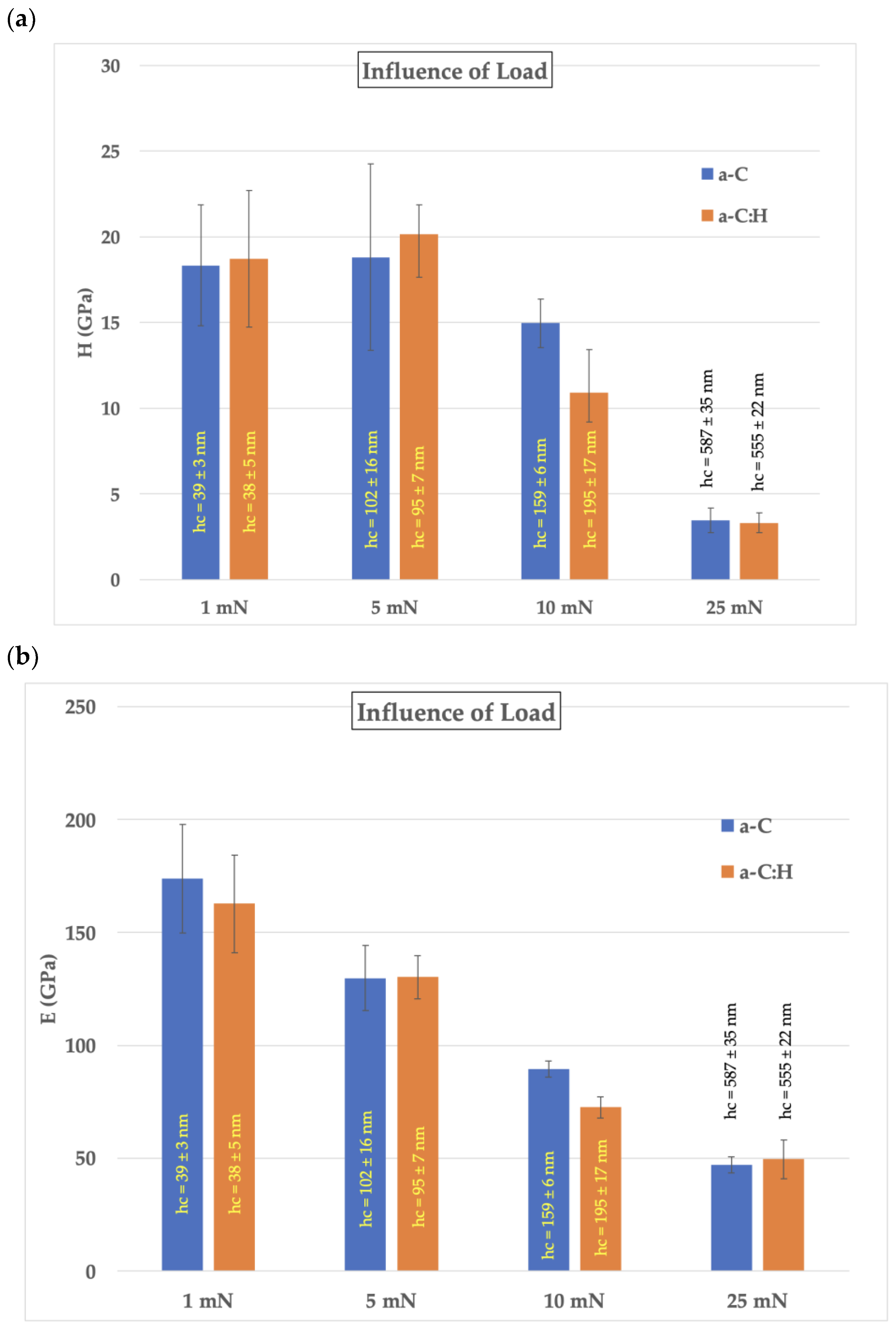
3.3. Nanoindentation

Although the main objective of the nanoindentation tests was the assessment of hardness, Young’s modulus, and resistance to plastic deformation of the coatings, they were also used to observe the influence of applied maximum load on these properties. This evaluation served to determine the optimal load value for performing the tests, to correlate the results with the thickness measurements, and to observe how H and E values vary with the penetration of the indenter. The influence of load on hardness and E of the a-C and a-C:H samples is shown in Figure 7a and Figure 7b, respectively. The indentation contact depth (hc) of each test is also shown. In the case of hardness, in both cases, the value is maintained with applied loads of 1 and 5 mN, while the influence of the substrate starts to appear with 10 mN, and it is evident with 25 mN. It can also be noted that, as was expected, with 10 mN, the influence of the substrate affected the a-C:H layer more, the thinner one, than the a-C layer. The variation is much more evident in the case of Young’s modulus. In this case, the influence of the substrate started to affect the measurement with an applied load of 5 mN, and it was similar for both the a-C and the a-C:H layer.
The results of hardness and Young’s modulus for the uncoated and coated samples are shown in Figure 8. Hardness and E are greater in the thin films, showing H values 18 times greater than the uncoated ones and 3.5 times greater in the case of E. Both coatings presented similar values of both H and E, with values of approximately 18 GPa and 165 GPa, respectively.
The relationship between H and E is defined by the ratios H3/E2 and H/E. These ratios are related to the resistance to plastic deformation in loaded contact and the elasticity index, respectively [56,57]. H3/E2 is used as an indicator of toughness given that it is related to the elastic limit of the material. Thus, an improvement in the elastic recovery of the coating, which is related to its toughness, will cause an increase in this ratio [57,58,59]. Furthermore, the relationship between these parameters and wear resistance has also been studied, proving that H/E and H3/E2 are more relevant than just hardness in determining good wear resistance of coatings [56,57,59,60]. The H3/E2 and H/E ratios calculated for the uncoated and coated samples are shown in Table 6. The coated samples showed a clear improvement in both ratios, but it is especially evident in the case of H3/E2, which went from a value of 0.0006 shown by the Mg ZK60 substrate to the values of 0.19–0.22 in the coated ones. These results indicate that the resistance to plastic deformation was considerably improved with the thin films, which should lead to an increase in toughness and wear resistance. In addition, parameters such as toughness and hardness are very important in increasing the fatigue life of a component [61,62], which is of great importance in applications such as biomedical implants or automotive.

3.4. Tribological Tests

The tribological properties of the substrate and coated samples were studied with pin-on-disk tests using different test parameters. The coefficient of friction (COF) values obtained after the tests for each sample are shown in Table 7. As can be seen, except for the first test, the other two showed a reduced value of the COF in the coated samples. In the most demanding test, i.e., the second one, the COF was reduced even more than 50% with the hydrogenated thin film. Even though the typical COF values for DLC coatings are around 0.1 [42,63], when it is applied on soft substrates such as Mg, several studies have shown values of approximately 0.3–0.4 [17,29,55]. The lower coefficient of friction values observed for the a-C:H coatings were expected because of more ordered graphitic structures and the higher hydrogen content on the surface shown in the Raman spectroscopy, leading to a lubricious behavior.
Figure 9 shows the evolution of the COF vs time for the coated samples in the most demanding test. At the beginning of the test, the a-C:H coating showed smaller COF values, but the tendency of both thin films was similar, showing results with low noise and dispersion. From approximately 800 s onwards, on the other hand, the behavior of the a-C coating changed completely, considerably increasing the scattering and noise of the measurements. This change is attributed to the failure of the coating at this point of the test caused by the delamination of the film due to its inability to withstand the stresses generated during the application of the load. These results are consistent with the greater critical loads that were observed in the scratch tests in the case of the a-C:H coating.
The wear coefficient (k) of each sample was calculated using the volume loss that was measured with confocal microscopy, and the results are presented in Figure 10. The lower the value of k, the higher the wear resistance, and as it can be seen in this case, both coatings improve the wear resistance of the substrate in all tests. Regarding the difference between the two coatings, the a-C:H coating presents smaller values in all cases, even attaining a reduction in an order of magnitude in the most demanding test. Wear rate values on the order of 10−6 were reported for micro-arc oxidation (MAO) + DLC coatings [17] and doped DLC coatings [33]. In both cases, the DLC coatings were thicker than in this study, about 2 μm for the MAO-supported layer and more than 3 μm for the doped DLCs. Other studies have analyzed wear resistance of thinner (0.6–1 μm) DLC coatings deposited on Mg, but they did not report wear rate values after tribological tests [29,30,55].
Images of the wear tracks of each sample for the three tests are shown in Figure 11. The uncoated samples showed grooves with heavy wear and many wear stripes on the track surface. Moreover, in test 2, the effect of adhesive wear on the wear track surface can be clearly seen. Since it is possible to observe areas with a large amount of wear debris material adhered to them. The a-C coating showed great wear in tests 1 and 2, with small regions of the wear track being affected by adhesive wear in the second one. In the last test, the effect of wear was much less aggressive. The a-C:H thin film presented the smoothest wear tracks. Adhesive wear was not observed in any of the tests, and the grooves were shallower and with significantly fewer wear marks. These images are in accordance with the results obtained for the wear coefficient. Lower values of k, shown by the a-C:H layer, were measured for the samples that were less affected by wear grooves. The involved wear mechanisms have a direct influence on the observed COF and k results since, in tribological tests, both the differences in test parameters and the observed wear mechanisms influence these results [64,65,66]. The highest amount of abrasive wear was observed in test 1 (higher COF values), while higher adhesive wear and plastic deformation were observed in test 2. The coated samples presented the smoothest surfaces in test 3, which caused lower COF values. In the case of the uncoated samples, due to the softness of the Mg, they also suffered from high abrasive wear in test 3, which led to higher COF values. In addition, in test 2, material removal was observed in the uncoated sample, which also caused the COF value to increase.
On the other hand, in test 1 the sample coated with a-C:H showed higher abrasive wear than in test 2. In abrasion wear mechanisms, it is common to observe that the asperities of the hard surface of the counterface material dig into the substrate. In this way, the material from the surface of the tested sample will be removed mainly by plowing, leading to the formation of grooves on the wear surface [67,68]. These grooves along the wear track lead to an increase in the wear rate value that is observed after measuring volume loss by confocal. In the case of test 2, abrasive wear grooves were replaced with shallow scratches accompanied by plastic deformation. Increasing sliding velocity and/or distance contact surface temperature can improve because of the generated frictional heat. In addition, the tendency of plastic deformation increases with higher velocity values. Consequently, instead of losing material because of the plowing action caused by abrasion, the material is displaced on both sides of the wear track without being removed [67,68]. Therefore, although the test conditions are more demanding in test 2 (higher sliding velocity and test time), the different wear mechanisms present in each case can explain why the wear coefficient presents these reduced values compared with test 1.

3.5. Corrosion Tests

Figure 12 shows the potentiodynamic polarization curves of uncoated ZK60 magnesium alloy and DLC-coated samples tested in NaCl, and electrochemical corrosion parameters, corrosion potential (Ecorr), and corrosion current density (icorr) obtained using Tafel slope extrapolation are presented in Table 8.
Similar values of current density were observed for the a-C:H coating and the uncoated samples, while both coatings presented values even higher than the uncoated substrate. Given that lower current density is associated with higher corrosion resistance, it seems clear that the thin films were not able to improve the corrosion resistance of the substrate. In the case of corrosion potential, more positive values are indicative of corrosion initiation tendency reduction because of the retardment of anodic kinetics on the coated samples. The uncoated samples presented the most negative corrosion potential values, −1.55 V, while the a-C and a-C:H samples possessed values of −1.40 and −1.33, respectively. Despite the small difference, the a-C:H coated samples showed better results than the a-C coated samples for both Ecorr and jcorr. However, they showed lower corrosion resistance than the uncoated samples, so it must be improved.
Figure 13 shows a photograph of both the a-C:H and a-C coated samples after 24 h of immersion, and Figure 14 shows SEM images obtained for both coatings after these tests. As can be seen, the solution penetrated the coating, causing its delamination and a clear accumulation of corrosion products. Roughness or defects on the surface could lead to the propagation of corrosion [69,70]. The thin films were not able to withstand the corrosive attack, and the surface was badly affected with obvious coating failure in less than 24 h of immersion. The fact that the solution was able to reach the substrate and cause the coating to fail is consistent with the results observed in the potentiodynamic tests. That is, the coatings did not provide an enhancement in corrosion resistance.
SEM-EDX analysis was performed to analyze the corroded surface of the coated samples after the immersion tests. With the mapping, it was possible to observe the presence of the different elements of the coating, substrate, and corroded zones in the studied area of the surface. Although visually, both thin films showed a highly corroded surface, as can be seen in Figure 15, it is still possible to observe the presence of carbon in areas with great accumulation of corrosion products in both coatings. However, there is a great presence of Mg and oxygen, which indicates that the solution penetrated through the thin film and corroded the substrate. The presence of Cr and W, elements from the interlayers, were also observed in both cases.

4. Discussion

In this study, two different DLC coatings were deposited over a Mg alloy using HiPIMS: a-C and a-C:H. The hydrogen-free coating had Cr and CrC transition layers to improve its adhesion, while the hydrogenated coating was deposited on a Cr transition layer followed by a WC layer. The a-C coating presented a total thickness of 900 nm compared with 400 nm for the a-C:H layer. A higher Raman signal was observed for a-C:H coatings due to the PL effect of hydrogenated coatings, and the G-peak was more predominant in these coatings. Hydrogen reduces the size of sp2 clusters and tends to reduce FWHM(G) and I(D)/I(G). A reduced coefficient of friction was also observed because of an increase in ordered graphitic structures and a higher presence of hydrogen, leading to a lubricious effect. The a-C coating, on the other hand, showed an important contribution of D-peak due to sp2 clustering. Raman spectroscopy performed after tribological tests also showed that the carbon structure did not undergo significant modifications after the tests and thus, extensive wear is associated with adhesive failure of the thin films.
Regarding the mechanical and surface properties, a slight increase in roughness (Sa) was observed for the a-C coating, while the a-C:H coating maintained the smoothness of the substrate prior to deposition. Although the difference was small, the hydrogenated coatings showed better adhesion values, with Lc2 and Lc3 values of 7 N and 12 N, respectively, versus 4 N and 9 N for the a-C coating. These results are similar and even higher than those presented by other studies where DLC coatings were deposited on Mg alloys, such as the adhesion strength values of 8.1 N presented by Cui et al. for Cr-DLC-coated AZ91D Mg alloy [51], or critical values of around 7 N shown for AZ 31 Mg alloy coated with Cr-DLC coatings [29]. WC-based interlayers have shown to be an effective way to improve the adhesion of Cr-doped DLC coatings on harder materials such as stainless steel [42] or WC-Co interlayer on AISI 1030 steel [71]. Both coatings led to improved H and E values when compared with the uncoated samples, with values of approximately 18 GPa and 165 GPa, respectively. Furthermore, the value of the H3/E2 and H/E ratios that are related to resistance to plastic deformation in loaded contact and the elasticity index, respectively [56,57], was increased with the DLC coatings. These results clearly show an improvement in resistance to plastic deformation, which may lead to an increase in toughness and wear resistance. In addition, it can be said that the mechanical properties and load support shown by the DLC thin films with both WC and CrC interlayers were similar. The main difference was the thickness of the amorphous carbon coatings. As a-C:H coatings are thinner, they accumulate less internal residual stress, which could be the reason for enhanced adhesion strength. The lower bombardment induced during the growth of a-C:H at reduced deposition time contributes to this stress reduction.
The a-C:H thin film showed better performance than the a-C coating in the tribological tests, with lower COF and k values. Both thin films presented lower COF values, 0.3–0.4 for a-C:H and 0.5–0.6 for a-C, compared with a value close to 1 in the case of the uncoated samples. Given the small thickness of the coatings and the low load-bearing capacity of the Mg substrates, small changes in speed or duration in the tribological tests showed large differences in the results. As the number of cycles or test speed increases, material pullout and coating wear are shown to be higher. Thus, the type of wear experienced by the samples is different (the predominance of abrasive or adhesive wear varies) and, therefore, the wear resistance results vary. In addition, varying the test conditions may result in different COF values [64,72].
The lower COF values observed for the a-C:H coatings are associated with the presence of C-H sp2 bonds that facilitate the formation of graphitic tribolayers during tribological tests. The hydrogenated coating presented lower K values in all the tribological tests, with differences up to an order of magnitude with respect to the hydrogen-free coated samples. In addition, delamination of the coating was observed in the a-C coating, leading to sharp changes in the COF curves and increased wear. The value of H3/E2 was practically the same in both coatings and the difference is even within the standard deviation of the measurements. Therefore, since both coatings have practically equal resistance to plastic deformation, the hydrogen content of the a-C:H layer makes the difference, showing lower friction and lubricating behavior, leading to higher wear resistance of this coating. So, the reduced COF and increased hardness of the surface in the case of the a-C:H thin films are responsible for the improved wear resistance.
In the case of corrosion resistance, the a-C:H-coated samples showed better results than the a-C-coated samples in the potentiodynamic tests. However, both coatings showed lower corrosion resistance than the substrate. The penetration and accumulation of the corrosive solution through the coating could lead to the acceleration of the degradation because of crevice corrosion leading to these results. Both thin films showed more positive corrosion potential values than the substrate, −1.40 for the a-C and −1.33 for the a-C:H samples versus −1.55 for the substrates. Even though this is associated with retardment of corrosion initiation tendency, given the results of current density, it is evident that the corrosion resistance of the coatings must be improved to protect Mg alloys. The results observed in the immersion tests reinforced this argument since the solution was able to penetrate the coating before 24 h, leading to the failure of the coatings and the accumulation of corrosion products. Both coatings were highly affected by corrosion, and, although in both cases, elements of the DLC layer were observed after immersion tests in the EDS characterization, both thin films showed a high presence of Mg and oxygen on the surface.
To sum up, it can be said that the hydrogenated thin film, despite being thinner, shows a better performance both tribologically and against corrosion. However, the corrosion resistance is still insufficient and needs to be improved to be able to properly functionalize magnesium alloys. The use of thicker layers or multilayers could be a good alternative to improve the protection of magnesium using this type of DLC coating.

5. Conclusions

The aim of this work was to improve the tribological and corrosion properties of magnesium alloys by depositing a-C and a-C:H thin films on magnesium alloy ZK60. After having shown and discussed all the results, some of the most relevant conclusions obtained in this work are summarized in the following points:
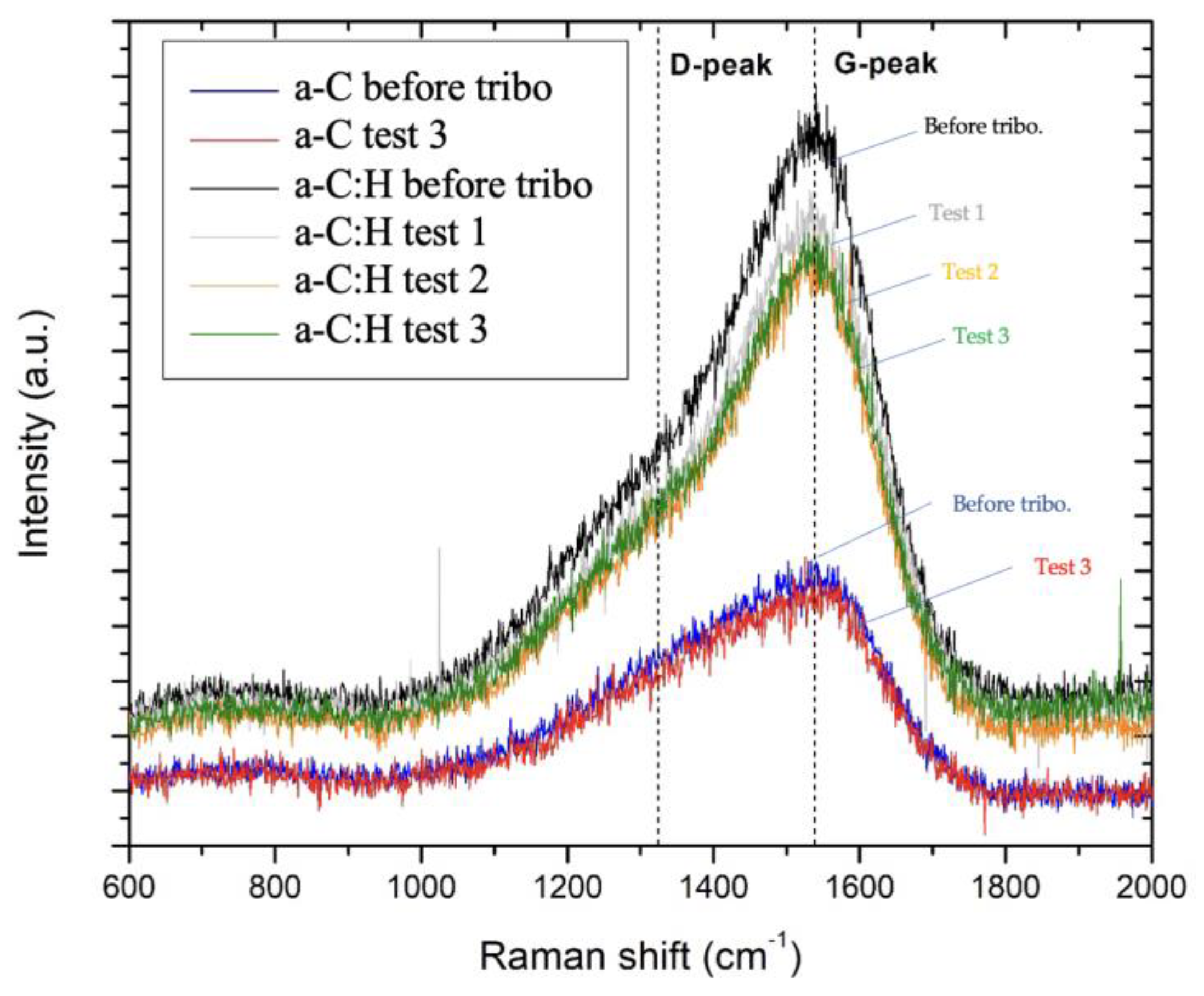
  • The Raman spectra of all the films showed a disordered amorphous carbon structure. The G-peak was more predominant in a-C:H coatings in the Raman spectroscopy due to the higher order of the graphitic structures, as well as the higher hydrogen content in the samples. These characteristics also explain the reduced coefficient of friction found for this sample.
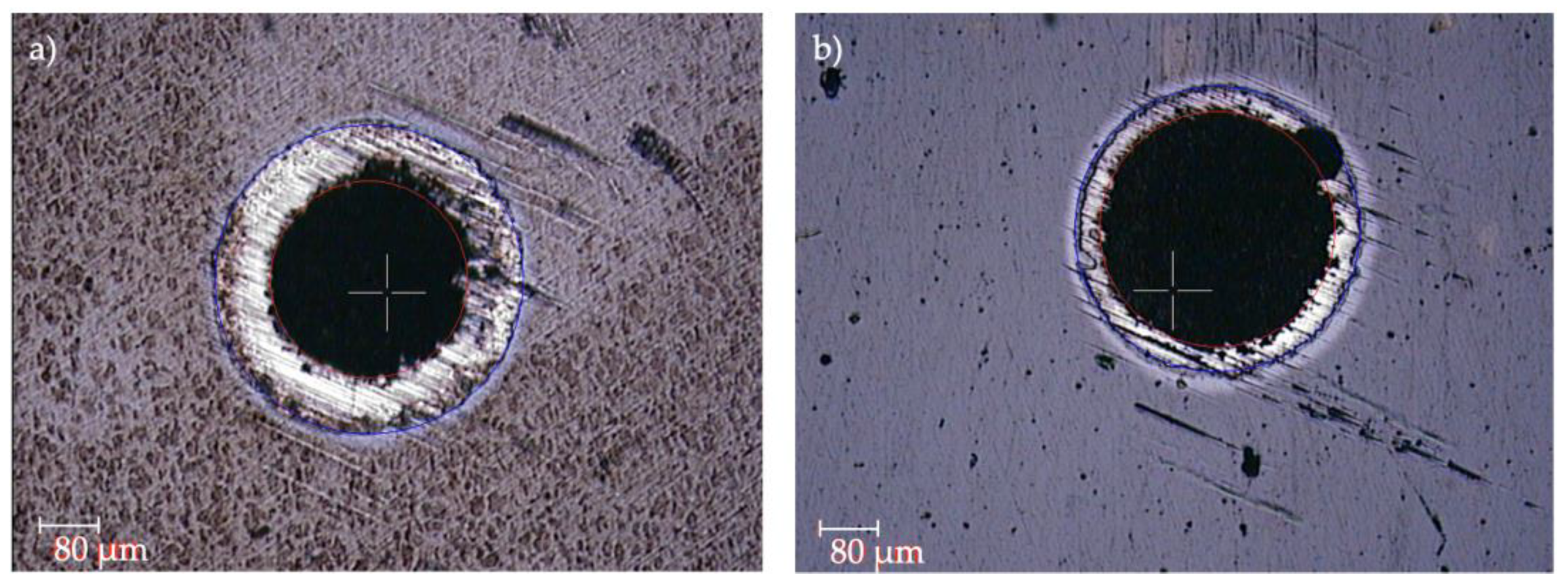
  • The a-C:H coating (Lc2 and Lc3 of 7 and 12 N, respectively) showed better adhesion to the substrate than the a-C coating (Lc2 and Lc3 of 4 and 9 N, respectively).
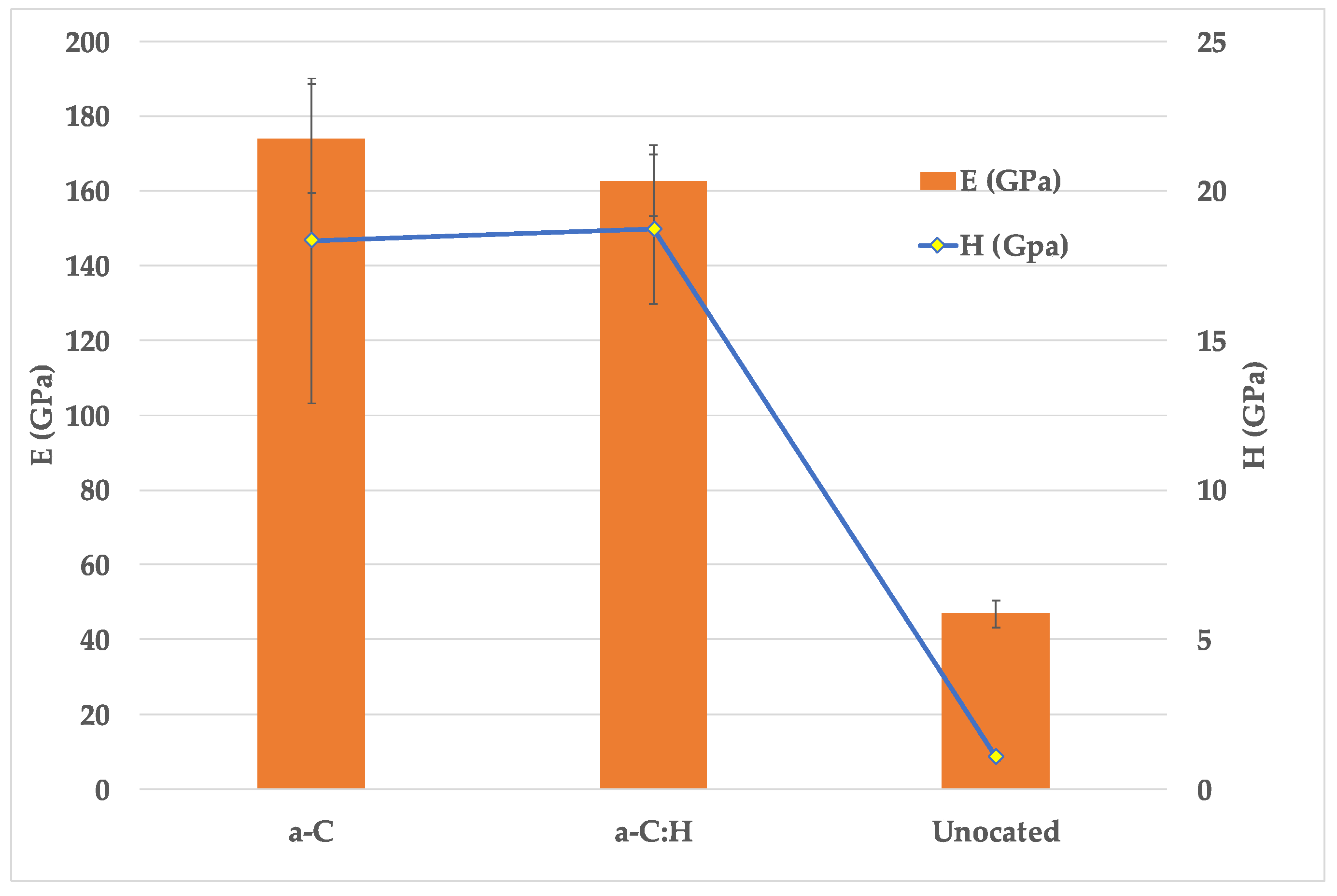
  • Nanoindentation results showed that both coatings improved H and E compared with the uncoated samples, with values of 18 GPa and 165 GPa, respectively. Furthermore, resistance to plastic deformation (H3/E2) was also improved.
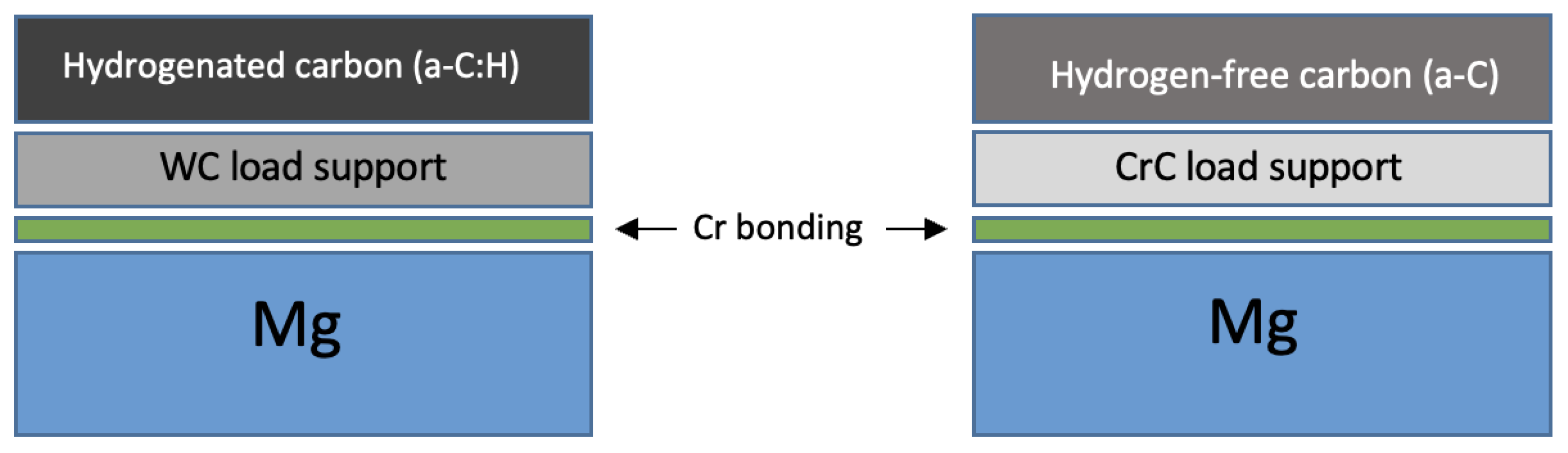
  • Mechanical properties, and load support shown by DLC thin films with both WC and CrC interlayers were similar, and the lower accumulation of internal stresses due to differences in thickness could be the reason for the enhanced adhesion strength of the a-C:H coating.
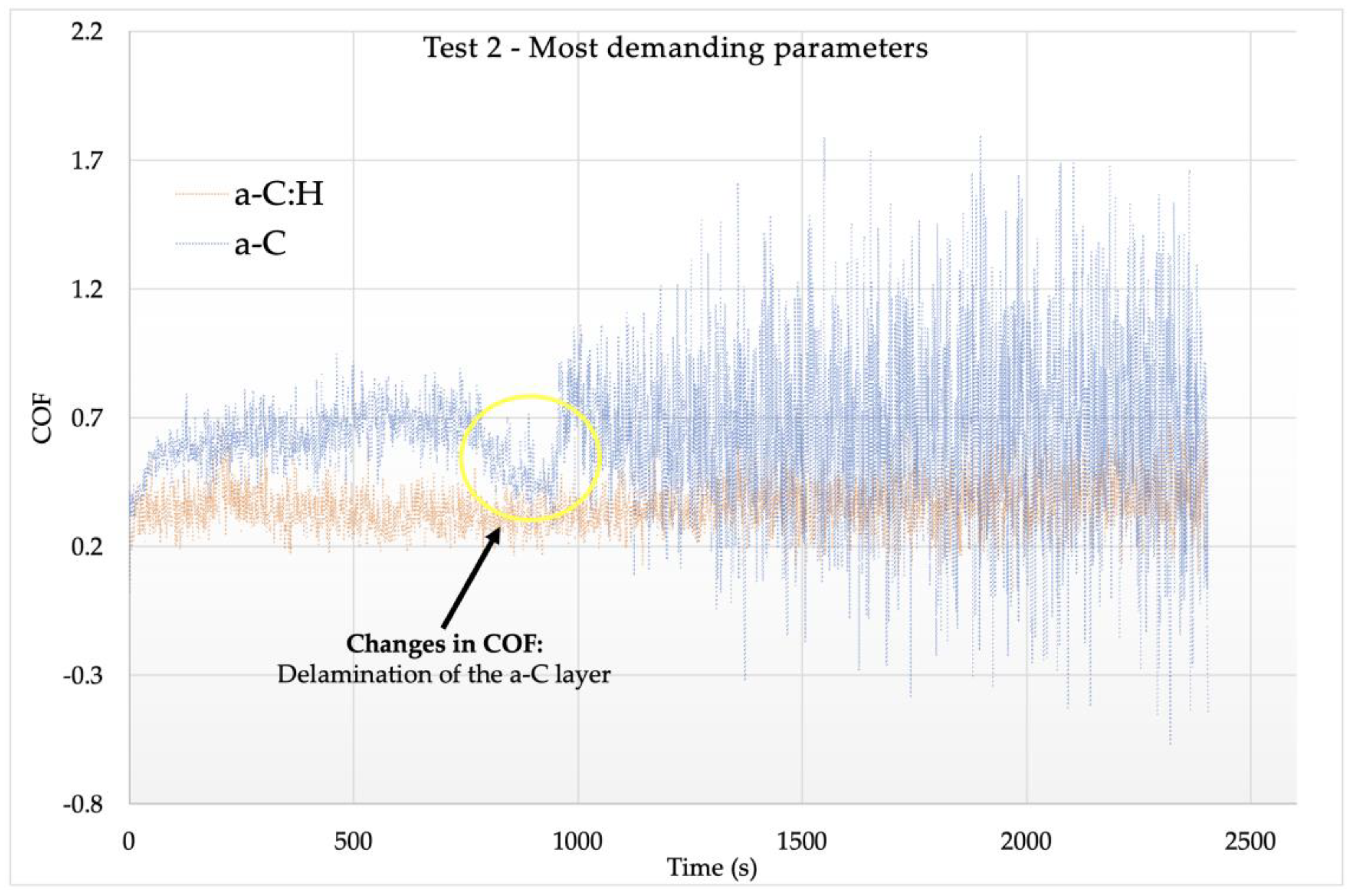
  • The addition of H was shown to be beneficial for the tribological performance of the coating. The a-C:H coating presented lower COF (0.3–0.4) and k (up to 10−5) values, while the a-C layer suffered delamination during the tests. The lower COF value of the a-C:H samples was of great relevance to improving wear resistance.
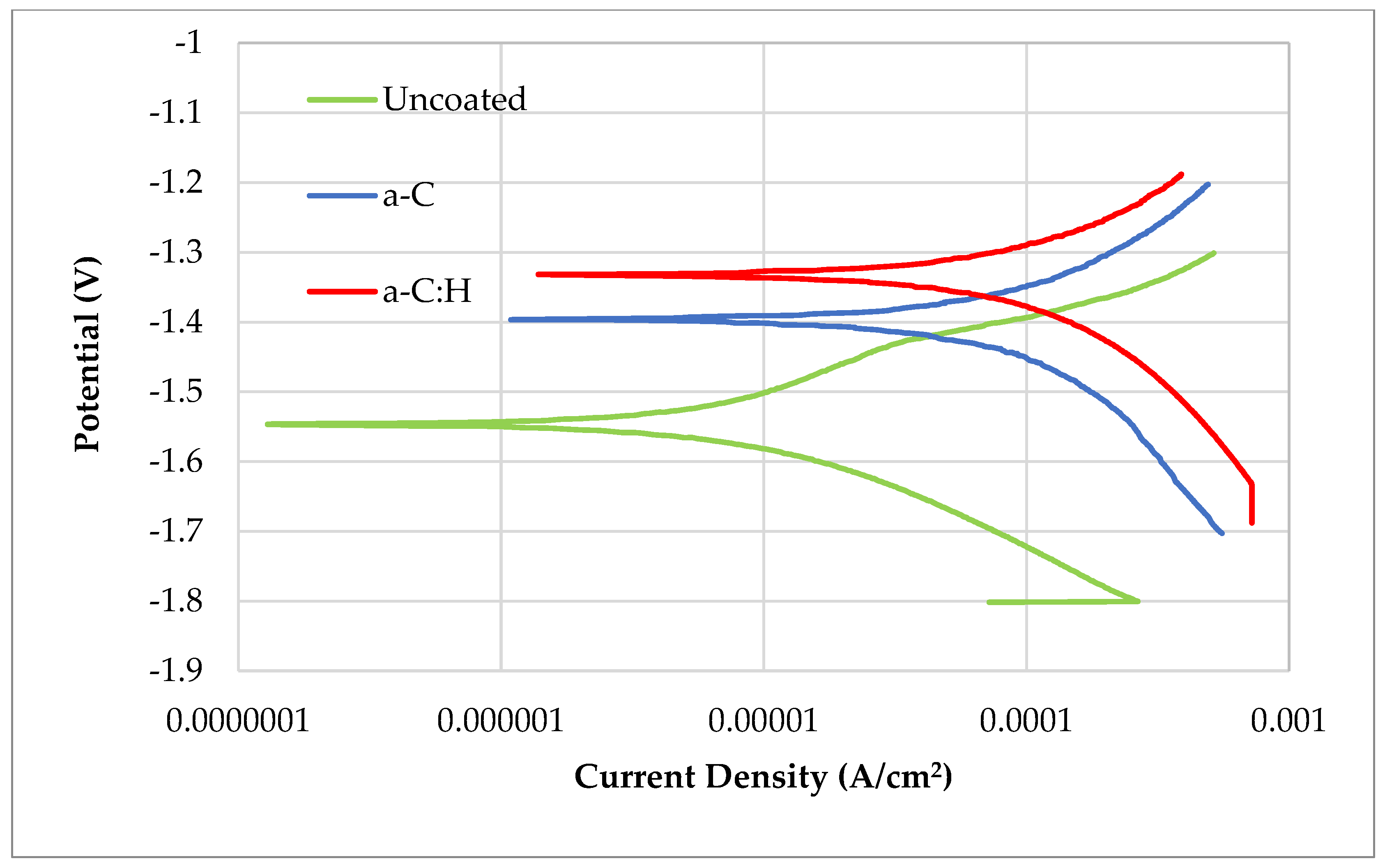
  • Although the a-C:H coating showed better results than the a-C coating in the corrosion tests, both proved to be insufficient to protect Mg against corrosion. Both failed in the immersion tests, but the hydrogenated coating was shown to maintain elements of the coating while the hydrogen-free one did not.
In summary, the a-C:H coating achieved better results in the tribological and corrosion tests, but the corrosion protection of both coatings was insufficient and must be improved. However, the benefit of using hydrogenated layers is evident, and corrosion protection could be improved by using thicker layers or multilayer structures.

Author Contributions

Conceptualization, A.C., I.F., J.A.S., G.G.F. and J.A.G.; methodology, A.C., I.Z. and J.A.G.; investigation, A.C., J.A.S., P.D.-R., M.P.-L., J.E. and J.F.P.; resources, A.C., I.F., I.Z. and J.A.G.; data curation, A.C., P.D.-R. and I.Z.; writing—original draft preparation, A.C.; writing—review and editing, A.C., J.A.S., J.E. and I.Z.; supervision, I.Z. and J.A.G.; project administration, A.C. and J.A.G.; funding acquisition, J.A.G. All authors have read and agreed to the published version of the manuscript.

Funding

This work was supported by the Gobierno de Navarra-Departamento de Desarrollo Económico through grant 0011-1410-2020-000006 “AM-MBI—Additive Manufacturing of Magnesiumbased Biodegradable Implants with Controlled Corrosion Rate and Infection”.

Institutional Review Board Statement

Not applicable.

Informed Consent Statement

Not applicable.

Data Availability Statement

No new data were created or analyzed in this study. Data sharing is not applicable to this article.

Conflicts of Interest

The authors declare no conflict of interest.

References

  1. Witte, F.; Kaese, V.; Haferkamp, H.; Switzer, E.; Meyer-Lindenberg, A.; Wirth, C.J.; Windhagen, H. In Vivo Corrosion of Four Magnesium Alloys and the Associated Bone Response. Biomaterials 2005, 26, 3557–3563. [Google Scholar] [CrossRef] [PubMed]
  2. Liu, B.; Yang, J.; Zhang, X.; Yang, Q.; Zhang, J.; Li, X. Development and Application of Magnesium Alloy Parts for Automotive OEMs: A Review. J. Magnes. Alloys 2023, 11, 15–47. [Google Scholar] [CrossRef]
  3. Johnston, S.; Shi, Z.; Atrens, A. The Influence of PH on the Corrosion Rate of High-Purity Mg, AZ91 and ZE41 in Bicarbonate Buffered Hanks’ Solution. Corros. Sci. 2015, 101, 182–192. [Google Scholar] [CrossRef]
  4. Wang, J.L.; Xu, J.K.; Hopkins, C.; Chow, D.H.K.; Qin, L. Biodegradable Magnesium-Based Implants in Orthopedics—A General Review and Perspectives. Adv. Sci. 2020, 7, 1902443. [Google Scholar] [CrossRef] [PubMed]
  5. Sezer, N.; Evis, Z.; Kayhan, S.M.; Tahmasebifar, A.; Koç, M. Review of Magnesium-Based Biomaterials and Their Applications. J. Magnes. Alloys 2018, 6, 23–43. [Google Scholar] [CrossRef]
  6. Zhang, S.; Zou, X.; Liu, N.; Wang, H.; Xia, C.; Liang, C. In Situ Preparation of a Novel Ta2O5/MAO Composite Coating on Magnesium for Anti-Corrosion Protection. Surf. Coat. Technol. 2022, 430, 128003. [Google Scholar] [CrossRef]
  7. Chen, Y.; Xu, Z.; Smith, C.; Sankar, J. Recent Advances on the Development of Magnesium Alloys for Biodegradable Implants. Acta Biomater. 2014, 10, 4561–4573. [Google Scholar] [CrossRef]
  8. Yang, Y.; He, C.; Dianyu, E.; Yang, W.; Qi, F.; Xie, D.; Shen, L.; Peng, S.; Shuai, C. Mg Bone Implant: Features, Developments and Perspectives. Mater. Des. 2020, 185, 108259. [Google Scholar] [CrossRef]
  9. Chandra, G.; Pandey, A. Preparation Strategies for Mg-Alloys for Biodegradable Orthopaedic Implants and Other Biomedical Applications: A Review. IRBM 2020, 43, 229–249. [Google Scholar] [CrossRef]
  10. Bairagi, D.; Mandal, S. A Comprehensive Review on Biocompatible Mg-Based Alloys as Temporary Orthopaedic Implants: Current Status, Challenges, and Future Prospects. J. Magnes. Alloys 2021, 10, 627–669. [Google Scholar] [CrossRef]
  11. Merlo, J.L.; Detsch, R.; Ceré, S.; Boccaccini, A.R.; Ballarre, J. Degradable Magnesium Implants: Improving Bioactive and Antibacterial Performance by Designed Hybrid Coatings. J. Mater. Res. 2021, 36, 443–458. [Google Scholar] [CrossRef]
  12. Altun, H.; Sen, S. The Effect of PVD Coatings on the Corrosion Behaviour of AZ91 Magnesium Alloy. Mater. Des. 2006, 27, 1174–1179. [Google Scholar] [CrossRef]
  13. Yang, Y.; Wu, P.; Wang, Q.; Wu, H.; Liu, Y.; Deng, Y.; Zhou, Y.; Shuai, C. The Enhancement of Mg Corrosion Resistance by Alloying Mn and Laser-Melting. Materials 2016, 9, 216. [Google Scholar] [CrossRef] [PubMed]
  14. Jian, S.-Y.; Ho, M.-L.; Shih, B.-C.; Wang, Y.-J.; Weng, L.-W.; Wang, M.-W.; Tseng, C.-C. Evaluation of the Corrosion Resistance and Cytocompatibility of a Bioactive Micro-Arc Oxidation Coating on AZ31 Mg Alloy. Coatings 2019, 9, 396. [Google Scholar] [CrossRef]
  15. Phani, A.R.; Gammel, F.J.; Hack, T.; Haefke, H. Enhanced Corrosioon Resistance by Sol-Gel-Based ZrO2-CeO2 Coatings on Magnesium Alloys. Mater. Corros. 2005, 56, 77–82. [Google Scholar] [CrossRef]
  16. Da Conceicao, T.F.; Scharnagl, N.; Blawert, C.; Dietzel, W.; Kainer, K.U. Surface Modification of Magnesium Alloy AZ31 by Hydrofluoric Acid Treatment and Its Effect on the Corrosion Behaviour. Thin Solid Films 2010, 518, 5209–5218. [Google Scholar] [CrossRef]
  17. Ning, C.-M.; Cui, X.-J.; Shang, L.-L.; Zhang, Y.-J.; Zhang, G.-A. Structure and Properties of Different Elements Doped Diamond-like Carbon on Micro-Arc Oxidation Coated AZ31B Mg Alloy. Diam. Relat. Mater. 2020, 106, 107832. [Google Scholar] [CrossRef]
  18. Bakhsheshi-Rad, H.R.; Hamzah, E.; Dias, G.J.; Saud, S.N.; Yaghoubidoust, F.; Hadisi, Z. Fabrication and Characterisation of Novel ZnO/MWCNT Duplex Coating Deposited on Mg Alloy by PVD Coupled with Dip-Coating Techniques. J. Alloys Compd. 2017, 728, 159–168. [Google Scholar] [CrossRef]
  19. Hoche, H.; Blawert, C.; Broszeit, E.; Berger, C. General Corrosion and Galvanic Corrosion Properties of Differently PVD Treated Magnesium Die Cast Alloy AZ91. Adv. Eng. Mater. 2003, 5, 896–902. [Google Scholar] [CrossRef]
  20. Donnet, C.; Erdemir, A. New Horizon in the Tribology of Diamondlike Carbon Films. Surf. Eng. 2008, 24, 399–401. [Google Scholar] [CrossRef]
  21. Erdemir, A.; Donnet, C. Tribology of Diamond-like Carbon Films: Recent Progress and Future Prospects. J. Phys. D Appl. Phys. 2006, 39, R311. [Google Scholar] [CrossRef]
  22. Dai, M.; Zhou, K.; Yuan, Z.; Ding, Q.; Fu, Z. The Cutting Performance of Diamond and DLC-Coated Cutting Tools. Diam. Relat. Mater. 2000, 9, 1753–1757. [Google Scholar] [CrossRef]
  23. Hauert, R.; Thorwarth, K.; Thorwarth, G. An Overview on Diamond-like Carbon Coatings in Medical Applications. Surf. Coat. Technol. 2013, 233, 119–130. [Google Scholar] [CrossRef]
  24. Treutler, C.P.O. Industrial Use of Plasma-Deposited Coatings for Components of Automotive Fuel Injection Systems. Surf. Coat. Technol. 2005, 200, 1969–1975. [Google Scholar] [CrossRef]
  25. Bewilogua, K.; Hofmann, D. History of Diamond-like Carbon Films—From First Experiments to Worldwide Applications. Surf. Coat. Technol. 2014, 242, 214–225. [Google Scholar] [CrossRef]
  26. Robertson, J. Diamond-like Amorphous Carbon. Mater. Sci. Eng. R Rep. 2002, 37, 129–281. [Google Scholar] [CrossRef]
  27. Picas, J.A.; Menargues, S.; Martin, E.; Colominas, C.; Baile, M.T. Characterization of Duplex Coating System (HVOF + PVD) on Light Alloy Substrates. Surf. Coat. Technol. 2017, 318, 326–331. [Google Scholar] [CrossRef]
  28. Lin, Y.H.; Da Lin, H.; Liu, C.K.; Huang, M.W.; Chen, J.R.; Shih, H.C. Structure and Characterization of the Multilayered Ti-DLC Films by FCVA. Diam. Relat. Mater. 2010, 19, 1034–1039. [Google Scholar] [CrossRef]
  29. Dai, W.; Wu, G.; Wang, A. Preparation, Characterization and Properties of Cr-Incorporated DLC Films on Magnesium Alloy. Diam. Relat. Mater. 2010, 19, 1307–1315. [Google Scholar] [CrossRef]
  30. Wu, G.; Dai, W.; Zheng, H.; Wang, A. Improving Wear Resistance and Corrosion Resistance of AZ31 Magnesium Alloy by DLC/AlN/Al Coating. Surf. Coat. Technol. 2010, 205, 2067–2073. [Google Scholar] [CrossRef]
  31. Yang, W.; Ke, P.; Fang, Y.; Zheng, H.; Wang, A. Microstructure and Properties of Duplex (Ti:N)-DLC/MAO Coating on Magnesium Alloy. Appl. Surf. Sci. 2013, 270, 519–525. [Google Scholar] [CrossRef]
  32. Yang, W.; Deng, Z.; Zhang, D.; Ke, P.; Wang, A. Microstructure and Tribological Behavior of Self-Lubricating (Si:N)-DLC/MAO Coatings on AZ80 Magnesium Substrate. Acta Metall. Sin. 2013, 26, 693–698. [Google Scholar] [CrossRef]
  33. Cui, X.J.; Ning, C.M.; Shang, L.L.; Zhang, G.A.; Liu, X.Q. Structure and Anticorrosion, Friction, and Wear Characteristics of Pure Diamond-Like Carbon (DLC), Cr-DLC, and Cr-H-DLC Films on AZ91D Mg Alloy. J. Mater. Eng. Perform. 2019, 28, 1213–1225. [Google Scholar] [CrossRef]
  34. Wu, G.; Sun, L.; Dai, W.; Song, L.; Wang, A. Influence of Interlayers on Corrosion Resistance of Diamond-like Carbon Coating on Magnesium Alloy. Surf. Coat. Technol. 2009, 204, 2193–2196. [Google Scholar] [CrossRef]
  35. Masami, I.; Setsuo, N.; Tsutomu, S.; Junho, C. Improvement of Corrosion Protection Property of Mg-Alloy by DLC and Si–DLC Coatings with PBII Technique and Multi-Target DC–RF Magnetron Sputtering. Nucl. Instrum. Methods Phys. Res. B 2009, 267, 1675–1679. [Google Scholar] [CrossRef]
  36. Chen, W.; Huang, J.; Peng, J. Characterisation of TiAlN PVD Coatings on AZ31 Magnesium Alloy. Res. Chem. Intermed. 2013, 41, 1257–1266. [Google Scholar] [CrossRef]
  37. Çelik, A.; Bozkurt, Y.B. Improvement of Tribological Performance of AZ31 Biodegradable Alloy by TiN-Based PVD Coatings. Tribol. Int. 2022, 173, 107684. [Google Scholar] [CrossRef]
  38. Hoche, H.; Groß, S.; Troßmann, T.; Schmidt, J.; Oechsner, M. PVD Coating and Substrate Pretreatment Concepts for Magnesium Alloys by Multinary Coatings Based on Ti(X)N. Surf. Coat. Technol. 2013, 228, S336–S341. [Google Scholar] [CrossRef]
  39. Hoche, H.; Groß, S.; Oechsner, M. Development of New PVD Coatings for Magnesium Alloys with Improved Corrosion Properties. Surf. Coat. Technol. 2014, 259, 102–108. [Google Scholar] [CrossRef]
  40. Claver, A.; Jiménez-Piqué, E.; Palacio, J.F.; Almandoz, E.; Fernández de Ara, J.; Fernández, I.; Santiago, J.A.; Barba, E.; García, J.A. Comparative Study of Tribomechanical Properties of HiPIMS with Positive Pulses DLC Coatings on Different Tools Steels. Coatings 2020, 11, 28. [Google Scholar] [CrossRef]
  41. Li, G.; Sun, J.; Xu, Y.; Xu, Y.; Gu, J.; Wang, L.; Huang, K.; Liu, K.; Li, L. Microstructure, Mechanical Properties, and Cutting Performance of TiAlSiN Multilayer Coatings Prepared by HiPIMS. Surf. Coat. Technol. 2018, 353, 274–281. [Google Scholar] [CrossRef]
  42. Santiago, J.A.; Fernández-Martínez, I.; Sánchez-López, J.C.; Rojas, T.C.; Wennberg, A.; Bellido-González, V.; Molina-Aldareguia, J.M.; Monclús, M.A.; González-Arrabal, R. Tribomechanical Properties of Hard Cr-Doped DLC Coatings Deposited by Low-Frequency HiPIMS. Surf. Coat. Technol. 2020, 382, 124899. [Google Scholar] [CrossRef]
  43. Wei, X.; Ma, J.; Ma, S.; Liu, P.; Qing, H.; Zhao, Q. Enhanced Anti-Corrosion and Biocompatibility of a Functionalized Layer Formed on ZK60 Mg Alloy via Hydroxyl (OH-) Ion Implantation. Colloids Surf. B Biointerfaces 2022, 216, 112533. [Google Scholar] [CrossRef] [PubMed]
  44. Murni, N.S.; Dambatta, M.S.; Yeap, S.K.; Froemming, G.R.A.; Hermawan, H. Cytotoxicity Evaluation of Biodegradable Zn–3Mg Alloy toward Normal Human Osteoblast Cells. Mater. Sci. Eng. C 2015, 49, 560–566. [Google Scholar] [CrossRef]
  45. Li, Y.; Wen, C.; Mushahary, D.; Sravanthi, R.; Harishankar, N.; Pande, G.; Hodgson, P. Mg–Zr–Sr Alloys as Biodegradable Implant Materials. Acta Biomater. 2012, 8, 3177–3188. [Google Scholar] [CrossRef]
  46. UNE-EN ISO 25178-2:2023; Geometrical Product Specifications (GPS)—Surface Texture: Areal—Part 2: Terms, Definitions and Surface Texture Parameters. UNE: Madrid, Spain, 2023. Available online: https://www.une.org/encuentra-tu-norma/busca-tu-norma/norma/?c=N0071403 (accessed on 2 October 2023).
  47. Oliver, W.C.; Pharr, G.M. An Improved Technique for Determining Hardness and Elastic Modulus Using Load and Displacement Sensing Indentation Experiments. J. Mater. Res. 1992, 7, 1564–1583. [Google Scholar] [CrossRef]
  48. ASTM G99—17; Standard Test Method for Wear Testing with a Pin-on-Disk Apparatus. ASTM International: West Conshohocken, PA, USA, 2017. Available online: https://www.astm.org (accessed on 2 October 2023).
  49. Kirkland, N.T.; Birbilis, N.; Staiger, M.P. Assessing the Corrosion of Biodegradable Magnesium Implants: A Critical Review of Current Methodologies and Their Limitations. Acta Biomater. 2012, 8, 925–936. [Google Scholar] [CrossRef]
  50. Witte, F. The History of Biodegradable Magnesium Implants: A Review. Acta Biomater. 2010, 6, 1680–1692. [Google Scholar] [CrossRef]
  51. Schwan, J.; Ulrich, S.; Batori, V.; Ehrhardt, H.; Silva, S.R.P. Raman Spectroscopy on Amorphous Carbon Films. J. Appl. Phys. 1996, 80, 440–447. [Google Scholar] [CrossRef]
  52. Marchon, B. Photoluminescence and Raman Spectroscopy in Hydrogenated Carbon Films. IEEE Trans. Magn. 1997, 33, 3148–3150. [Google Scholar] [CrossRef]
  53. Marin, E.; Lanzutti, A.; Nakamura, M.; Zanocco, M.; Zhu, W.; Pezzotti, G.; Andreatta, F. Corrosion and Scratch Resistance of DLC Coatings Applied on Chromium Molybdenum Steel. Surf. Coat. Technol. 2019, 378, 124944. [Google Scholar] [CrossRef]
  54. Santiago, J.A.; Fernández-Martínez, I.; Wennberg, A.; Molina-Aldareguia, J.M.; Castillo-Rodríguez, M.; Rojas, T.C.; Sánchez-López, J.C.; González, M.U.; García-Martín, J.M.; Li, H.; et al. Adhesion Enhancement of DLC Hard Coatings by HiPIMS Metal Ion Etching Pretreatment. Surf. Coat. Technol. 2018, 349, 787–796. [Google Scholar] [CrossRef]
  55. Molak, R.M.; Topolski, K.; Spychalski, M.; Dulińska-Molak, I.; Morończyk, B.; Pakieła, Z.; Nieużyła, L.; Mazurkiewicz, M.; Wojucki, M.; Gebeshuber, A.; et al. Functional Properties of the Novel Hybrid Coatings Combined of the Oxide and DLC Layer as a Protective Coating for AZ91E Magnesium Alloy. Surf. Coat. Technol. 2019, 380, 125040. [Google Scholar] [CrossRef]
  56. Leyland, A.; Matthews, A. On the Significance of the H/E Ratio in Wear Control: A Nanocomposite Coating Approach to Optimised Tribological Behaviour. Wear 2000, 246, 1–11. [Google Scholar] [CrossRef]
  57. Charitidis, C.A. Nanomechanical and Nanotribological Properties of Carbon-Based Thin Films: A Review. Int. J. Refract. Met. Hard Mater. 2010, 28, 51–70. [Google Scholar] [CrossRef]
  58. Galvan, D.; Pei, Y.T.; De Hosson, J.T.M. Deformation and Failure Mechanism of Nano-Composite Coatings under Nano-Indentation. Surf. Coat. Technol. 2006, 200, 6718–6726. [Google Scholar] [CrossRef]
  59. Lopes, B.B.; Rangel, R.C.C.; Antonio, C.A.; Durrant, S.F.; Cruz, N.C.; Rangel, E.C. Mechanical and Tribological Properties of Plasma Deposited A-C:H:Si:O Films. In Nanoindentation in Materials Science; Nemecek, J., Ed.; IntechOpen: Rijeka, Croatia, 2012; Chapter 8. [Google Scholar]
  60. Mayrhofer, P.H.; Mitterer, C.; Musil, J. Structure-Property Relationships in Single-and Dual-Phase Nanocrystalline Hard Coatings. Surf. Coat. Technol. 2003, 174, 725–731. [Google Scholar] [CrossRef]
  61. Suh, C.M.; Hwang, B.W.; Murakami, R.I. Behaviors of Residual Stress and High-Temperature Fatigue Life in Ceramic Coatings Produced by PVD. Mater. Sci. Eng. A 2003, 343, 1–7. [Google Scholar] [CrossRef]
  62. Bai, Y.Y.; Gao, J.; Guo, T.; Gao, K.W.; Volinsky, A.A.; Pang, X.L. Review of the Fatigue Behavior of Hard Coating-Ductile Substrate Systems. Int. J. Miner. Metall. Mater. 2021, 28, 46–55. [Google Scholar] [CrossRef]
  63. Duminica, F.-D.; Belchi, R.; Libralesso, L.; Mercier, D. Investigation of Cr(N)/DLC Multilayer Coatings Elaborated by PVD for High Wear Resistance and Low Friction Applications. Surf. Coat. Technol. 2018, 337, 396–403. [Google Scholar] [CrossRef]
  64. Li, Y.; Meng, D.; Feng, Z.; She, D.; Yue, W. Effect of Different Working Conditions on Tribological Behaviors of PcBN/440c Stainless Steel in Vacuum Environment. Int. J. Refract. Met. Hard Mater. 2023, 116, 106366. [Google Scholar] [CrossRef]
  65. Sivaprakasam, P.; Hailu, T.; Elias, G. Experimental Investigation on Wear Behavior of Titanium Alloy (Grade 23) by Pin on Disc Tribometer. Results Mater. 2023, 19, 100422. [Google Scholar] [CrossRef]
  66. Wei, T.Z.; Shamsuri, S.R.B.; Chang, S.Y.; Rashid, M.W.A.; Ahsan, Q. Effect of Sliding Velocity on Wear Behavior of Magnesium Composite Reinforced with SiC and MWCNT. Procedia Eng. 2013, 68, 703–709. [Google Scholar] [CrossRef]
  67. Dixit, T.; Prasad, K.E. Effect of Temperature and Sliding Velocity on the Dry Sliding Wear Mechanisms of Boron Modified Ti-6Al-4V Alloys. Lubricants 2022, 10, 296. [Google Scholar] [CrossRef]
  68. Fisher, J.; Dowson, D.; Hamdzah, H.; Lee, H.L. The Effect of Sliding Velocity on the Friction and Wear of UHMWPE for Use in Total Artificial Joints. Wear 1994, 175, 219–225. [Google Scholar] [CrossRef]
  69. Zhu, W.; Yu, Z.; Yang, C.; Dong, F.; Ren, Z.; Zhang, K. Spatial Distribution of Corrosion Products Influenced by the Initial Defects and Corrosion-Induced Cracking of the Concrete. J. Test. Eval. 2023, 51, 2582–2597. [Google Scholar] [CrossRef]
  70. Zhu, W.; Yang, C.; Yu, Z.; Xiao, J.; Xu, Y. Impact of Defects in Steel-Concrete Interface on the Corrosion-Induced Cracking Propagation of the Reinforced Concrete. KSCE J. Civ. Eng. 2023, 27, 2621–2628. [Google Scholar] [CrossRef]
  71. Bolelli, G.; Lusvarghi, L.; Montecchi, M.; Mantini, F.P.; Pitacco, F.; Volz, H.; Barletta, M. HVOF-Sprayed WC-Co as Hard Interlayer for DLC Films. Surf. Coat. Technol. 2008, 203, 699–703. [Google Scholar] [CrossRef]
  72. Wahlström, J. A Pin-on-Disc Tribometer Study of Friction at Low Contact Pressures and Sliding Speeds for a Disc Brake Material Combination. Results Eng. 2019, 4, 100051. [Google Scholar] [CrossRef]
Figure 1. Horizontal cross-section scheme of the sputtering chamber used to prepare the coatings.
Coatings 13 01871 g001
Figure 2. Scheme of the coating layer disposition.
Coatings 13 01871 g002
Figure 3. Raman spectroscopy results for the a-C and a-C:H coatings before and after tribology.
Coatings 13 01871 g003
Figure 4. Calotest grooves: (a) a-C and (b) a-C:H coatings.
Coatings 13 01871 g004
Figure 5. Scratch test wear track after applying the increasing load: (a,b) a-C coating and (c,d) a-C:H coating.
Coatings 13 01871 g005
Figure 6. Critical load values, Lc2 and Lc3, of the a-C (blue plots) and a-C:H (orange plots) coatings.
Coatings 13 01871 g006
Figure 7. Influence of applied maximum load value in nanoindention tests for the a-C (blue plot) and a-C:H (orange plot) coatings: (a) hardness results and (b) Young’s modulus results.
Coatings 13 01871 g007
Figure 8. Young’s modulus (E) and hardness (H) values for uncoated and the a-C and a-C:H coatings for a maximum load of 1 mN.
Coatings 13 01871 g008
Figure 9. COF versus time measured during tribological tests for both the a-C and a-C:H coatings.
Coatings 13 01871 g009
Figure 10. Wear coefficient (k) measured for the coated and uncoated samples for each test: a-C coating (blue plots), a-C:H coating (orange plots), and uncoated samples (grey plots).
Coatings 13 01871 g010
Figure 11. Images of the wear tracks obtained for each sample in the 3 different tests that were performed.
Coatings 13 01871 g011
Figure 12. Potentiodynamic polarization curves of uncoated and coated samples.
Coatings 13 01871 g012
Figure 13. Surface of coated samples after 24 h of immersion in NaCl.
Coatings 13 01871 g013
Figure 14. SEM images obtained for each coated sample after 24 h immersion tests: (a) a-C coating and (b) a-C:H coating.
Coatings 13 01871 g014
Figure 15. SEM-EDX results for each coating: (a) a-C coating and (b) a-C:H coating.
Coatings 13 01871 g015
Table 1. Chemical composition and mechanical properties of the magnesium alloy ZK60A-T5.
AlZnMnFeCuZrNiSiMg
%0.00125.70.0330.00250.00170.540.00120.0027Reminder
Mechanical
Properties
Tensile Strength:
322 Mpa
Yield Strength:
256 MPa
Elongation:
10%
Table 2. Sample surface conditioning process description.
StepProcessMaterial
1GroundingSiC emery paper: from 180 to 1200 grit size
2Cleaning and rinsingDistilled water and ethanol
3Polishingpolishing cloths and diamond polycrystalline suspension (particle size 9 and 1 µm)
4CleaningUltrasonic cleaning with ethanol and drying in air
Table 3. Description of the pretreatment and deposition process.
StepProcessDescription
1Ar etchingAr+ discharge established at the substrates:
15 min, DC-pulsed bias voltage of −500 V, and a frequency of 150 kHz.
2Bonding layerCr target operated in HiPIMS:
  • Pulsing time: 150 μs.
  • Repetition frequency: 300 Hz.
  • Average power density: 5 W/cm2.
  • Substrate voltage bias: −750 V to −100 V.
  • Deposition rate (three-fold rotation) at a substrate voltage bias of −100 V: 0.5 µm/h.
3InterlayerWC interlayer:
  • DC-pulsed mode.
  • Power density of 7.5 W/cm2.
  • Frequency rate of 150 kHz.
  • Pulse width of 2.7 μs.
  • Deposition rate for a three-fold rotation at a substrate voltage bias of −100 V: 0.38 µm/h.
CrC interlayer:
  • Carbon (4 kW) and Cr (0.5 kW) in HiPIMS mode.
  • Cr: pulsing time 150 μs, repetition frequency 300 Hz.
  • Carbon: pulsing time 100 μs, repetition frequency 600 Hz.
4DLC coatinga-C:H coating:
  • HiPIMS mode.
  • Pulsing time: 100 µs and 600 Hz.
  • Substrate voltage bias: −70 V.
  • Deposition rate obtained (three-fold rotation): 0.25 µm/h.
  • Acetylene flux of 15 sccm incorporated for hydrogenated carbon.
Table 4. Pin-on-disk test parameters for each test.
Fn (N)Ω (rpm)Duration (Cycles)Radius (mm)
Test 11150200016
Test 21150600018
Test 31100300022
Table 5. Roughness values measured using confocal for the coated and uncoated samples.
SampleRoughness Sa (nm)
Uncoated ZK 6019 ± 4
a-C44 ± 8
a-C:H18 ± 1
Table 6. H3/E2 and H/E ratios calculated for the uncoated and coated samples from the results obtained from the nanoindentation tests with 1 mN of maximum load.
Uncoateda-Ca-C:H
H3/E20.0006 ± 0.00010.22 ± 0.060.19 ± 0.03
H/E0.02 ± 0.000.11 ± 0.010.12 ± 0.01
Table 7. COF values of uncoated, a-C-coated, and a-C:H-coated samples for each test performed.
COF ValuesTest 1Test 2Test 3
Uncoated0.411.2
a-C0.80.60.5
a-C:H0.50.40.3
Table 8. Corrosion potential and current density values of coated and uncoated samples.
SampleEcorr (V)jcorr (µA/cm2)
Uncoated ZK 60−1.55 ± 0.017.2 ± 0.7
a-C−1.40 ± 0.0291.4 ± 5
a-C:H−1.33 ± 0.0321.9 ± 0.2
Disclaimer/Publisher’s Note: The statements, opinions and data contained in all publications are solely those of the individual author(s) and contributor(s) and not of MDPI and/or the editor(s). MDPI and/or the editor(s) disclaim responsibility for any injury to people or property resulting from any ideas, methods, instructions or products referred to in the content.

