Article

Microstructure and Mechanical Properties of Magnetron Sputtering TiN-Ni Nanocrystalline Composite Films

1
School of Materials Science, Shanghai Dianji University, Shanghai 200240, China
2
Blasting and Coating Department, Shanghai Waigaoqiao Shipbuilding and Offshore Co., Ltd., Shanghai 201306, China
3
Department of Mechanical Engineering, CEMMPRE, ARISE, University of Coimbra, Rua Luís Reis Santos, 3030-788 Coimbra, Portugal
4
School of Materials Science and Engineering, Jiangsu University of Science and Technology, Zhenjiang 212003, China
5
ISEP, Polytechnic of Porto, Rua Dr. António Bernardino de Almeida, 4249-015 Porto, Portugal
*
Author to whom correspondence should be addressed.
Coatings 2023, 13(11), 1902; https://doi.org/10.3390/coatings13111902
Submission received: 12 September 2023 / Revised: 24 October 2023 / Accepted: 27 October 2023 / Published: 6 November 2023

Abstract

:
In this paper, TiN-Ni nanostructured composite films with different Ni contents are prepared using the magnetron sputtering method. The composition, microstructure, and mechanical properties of composite films are analyzed using an X-ray energy spectrometer (EDS), a scanning electron microscope (SEM), X-ray diffraction technology (XRD), a transmission electron microscope (TEM), and nanoindentation. All the films grow in a columnar crystal structure. There are only TiN diffraction peaks in the XRD spectrum, and no diffraction peaks of Ni and its compounds are observed. The addition of the Ni element disrupts the integrity of TiN lattice growth, resulting in a decrease in the grain size from 60 nm in TiN to 25 nm at 20.6% Ni. The film with a Ni content of 12.4 at.% forms a nanocomposite structure in which the nanocrystalline TiN phase (nc-TiN) is surrounded by the amorphous Ni (a-Ni) phase. The formation of nc-TiN/a-Ni nanocomposite structures relies on the good wettability of Ni on TiN ceramics. The hardness and elastic modulus of the film gradually decrease with the increase in Ni content, but the toughness is improved. The hardness and elastic modulus decrease from 19.9 GPa and 239.5 GPa for TiN film to 15.4 GPa and 223 GPa at 20.6 at.% Ni film, respectively, while the fracture toughness increases from 1.5 MPa·m1/2 to 2.0 MPa·m1/2. The soft and ductile Ni phase enriched at the TiN grain boundaries hinders the propagation of cracks in the TiN phase, resulting in a significant increase in the film’s toughness. The research results of this paper provide support for the design of TiN-Ni films with high strength and toughness and the understanding of the formation mechanism of nanocomposite structures.

1. Introduction

Transition group metal nitride films are often widely used as wear-resistant coatings in aerospace and other fields. As a representative, TiN-based films have been widely studied due to their excellent properties, such as high hardness and high wear resistance [1,2,3,4,5]. At present, the hardness of TiN-based films can be increased to more than 40 GPa by adding alloying elements to form nanocomposite films or through structural design to form superlattice structures [6,7]. However, excellent wear resistance depends not only on the improvement of film hardness but also on excellent toughness.
Musil et al. [8] proposed a method to improve the toughness of such materials: nc-MeN/soft metal nanocomposite structure, in which nanocrystalline MeN was wrapped with a thin layer of soft metal. However, this structure was not easily accessible. Some studies show that a nanocomposite structure with a Ni phase surrounding TiN grains can be formed in the TiN-Ni system. Therefore, a large amount of work has been conducted to investigate the influence of deposition parameters, such as target composition, substrate temperature, process gas pressure, target current, and substrate bias voltage, on the microstructure and properties of TiN-Ni thin films [9,10,11,12]. For example, Mitra et al. [13] investigated the effect of substrate bias on the structure and mechanical properties of magnetron sputtered Ni-TiN coatings. The results indicated that due to high-energy ion bombardment, the higher the negative bias voltage, the finer the nanocomposite structure obtained. This led to a lower friction coefficient and better wear resistance of the coating. By changing the composition of the cathode of TiNi alloy, Akhter et al. [14] prepared a TiNiN coating with a Ni content of 2~20 at.% by using cathodic arc evaporation. The effect of Ni content on the microstructure and mechanical properties of coatings was studied. They reported that the TiNiN film containing approximately 4 at.% Ni prepared using Ti90Ni10 (at.%) alloy target achieved the best mechanical properties (hardness of 32 GPa, elastic modulus of 316 GPa). Irie et al. [15] deposited TiN-Ni nanocomposite films on hard alloy (WC-Co) substrates usingcathodic arc ion plating. The film formeda grid structure where TiN grains were surrounded by metallic Ni phases. As the Ni content increasedfrom 5 at.% to 30 at.%, the hardness of the film gradually decreased from 28 GPa to23 GPa.
In summary, most current research focus on the effect of process parameters on the microstructure and mechanical properties of composite films. The evaluation of film toughness also mostly uses indirect indicators such as H/E and H3/E2.In this article, a series of TiN-Ni nanocomposite films are prepared using a reactive magnetron co-sputtering method. The mechanical behavior of films is studied and the toughness is quantitatively calculated using an indentation method. The formation mechanism of film nanocomposite structures is revealed.

2. Experimental

2.1. Film Preparation

The TiN-Ni nanocomposite structure films in this paper are prepared using the ANAVA SPC-350 magnetron sputtering system (Anelva, Tokyo, Japan). The substrate is monocrystalline silicon wafer. The Si substrates are ultrasonically washed in acetone and alcohol for 15 min, dried, and fixed on a rotatable substrate rack in the chamber. The chamber is vacuumed to 5.0 × 10⁻⁴ Pa, and filled with high-purity argon (99.99%) and nitrogen (99.99%). During the deposition process, the working pressure is fixed at 0.3 Pa. The Ar flow rate is set to 20 sccm, while 6 sccm is the setting for the N2 flow rate. One pure Ti target (99.9%) and one Ni target (99.9%) with a diameter of 76 mm are controlled by a DC cathode and an RF cathode, respectively. The power of the DC Ti target is controlled at 200 W. The power of the RF Ni target is set to 0 W, 5 W, 10 W, 15 W, 20 W, and 30 W, respectively. Thus, a series of TiN-Ni nanocomposite thin films with different Ni content are obtained. The deposition time of each sample is 2 h, and the substrate is not heated or negatively biased.

2.2. Film Characterization

The Bruker’s D8 X-ray diffraction (XRD) with Cu Kα target is used to analyze the phase composition of thin films. The 2θ angle ranges from 30–80°. The elemental contents of films are tested using EDAX attached to the Hitachi’s S-3400N scanning electron microscope (Hitachi, Tokyo, Japan). The microstructure of the films is analyzed by performing JEOL JEM-2100F transmission electron microscopy (TEM) (JEOL, Tokyo, Japan). The cross-sectional morphology and thickness of the films are observed and measured using a ZEISS’ Gemini300 field emission scanning electron microscope (SEM) (Zeiss, Oberkochen, Germany). Chemical compositions are characterized by using scanning electron microscopy (SEM) with an attached energy-dispersive X-ray analyzer (EDX, Oxford instruments INCA) (Oxford Instruments, Oxford, England). The Anton Paar’s Step300-NTH3 nanoindenter (Anton Paar, Graz, Austria) with a Berkovich indenter is used to measure the mechanical properties of the films. The maximum load is 4 mN, both the loading and unloading times are all 20 s, and the holding time is 10 s. The loading and unloading curves are analyzed using the Oliver–Pharr method [16] to obtain the hardness and elastic modulus information of the film. Each sample is averaged after measuring at least 10 points to ensure the accuracy of the test results. The indentation tests with 200 mN are also performed using this nanoindenter. The indentation morphology is characterized by an optical microscope (OM) attached to the nanoindenter.

3. Results

Figure 1 shows the variations of Ti, Ni, and N contents with Ni target power that were obtained using EDS analysis. As the Ni target power increases, the Ni content in the film gradually increases to 20.6 at.%. Correspondingly, the content of Ti and N shows a decreasing trend.
Figure 2 shows the cross-sectional SEM image of TiN-Ni nanocomposite films with different Ni content. It can be seen that the thickness of the TiN film is about 270 nm. The thickness of the film gradually increases with the increase in Ni content, and increases to 320 nm when the Ni content is 20.6 at.%. In addition, all films exhibit a columnar crystal growth structure. In the films with 0–12.4 at.% Ni content, the columnar crystals grow through the film. When the Ni content increases to 16.1 and 20.6 at.%, the columnar crystal growth in the film is interrupted, showing a short fine columnar crystal morphology. The results show that the addition of Ni hinders the growth of columnar crystals and refines the grain structure of the film.
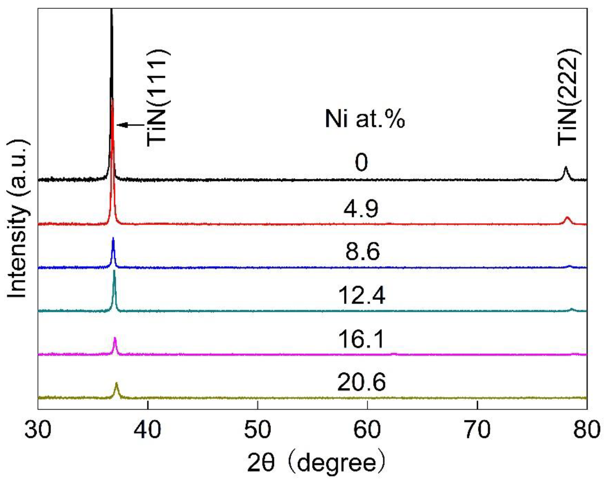
Figure 3 shows the XRD patterns of TiN-Ni films with different Ni content. The XRD patterns of all the films in the figure show a set of TiN diffraction peaks with a NaCl structure. There are no diffraction peaks of Ni and its compounds. This indicates that Ni exists in the film in solution or amorphous form. It can also be seen that as the Ni content increases, the height of the diffraction peak gradually decreases, and the width becomes greater. This is because a large number of TiN lattice distortions caused by the solid solution of Ni atoms cause the grains of the thin film to be gradually refined. In addition, with the increase in Ni content, the peak’s position is also observed to shift to a large angle. This is due to the fact that the radius of the Ni atom (0.124 nm) is less than that of the Ti atom (0.145 nm). The solution of Ni atoms causes the shrinkage of the TiN lattice.
According to the XRD patterns of Figure 3, the grain sizes of films can be calculated using the Scherrer formula. The relationship between grain size and the Ni content is shown in Figure 4. The grain size of the TiN film is about 60 nm. With the increase in Ni content, the grain size of the film gradually decreases to about 25 nm at 20.6 at.% Ni. This shows that the addition of Ni refines the grains of the films.
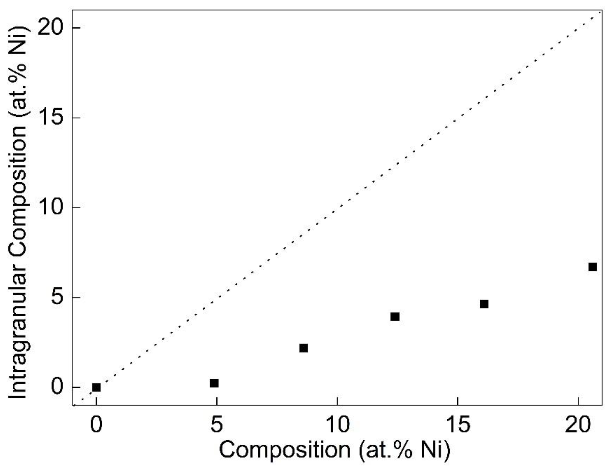
By referring to the XRD results in Figure 3, the lattice constant of each thin film can be obtained. Then, the relationship between the intragranular Ni content and the total Ni content of the films can be calculated using Vegard’s law [17]:
a = x a N i + 1 x a T i N
where a is the lattice constant of the films, x is the intragranular Ni content, and a N i and a T i N are the lattice constants of Ni and TiN, respectively.
The calculation results are shown in Figure 5 (black squares). The dotted line is the point where the intragranular Ni content is equal to the total Ni content. As illustrated, although the intragranular Ni content increases with the increase in the total Ni content, it is always slightly lower. This indicates that not all the Ni atoms are solidly soluble in the lattice of TiN. Furthermore, no diffraction peaks of Ni were found in the XRD results. Therefore, it is speculated that excess Ni may exist at grain boundaries in amorphous form.
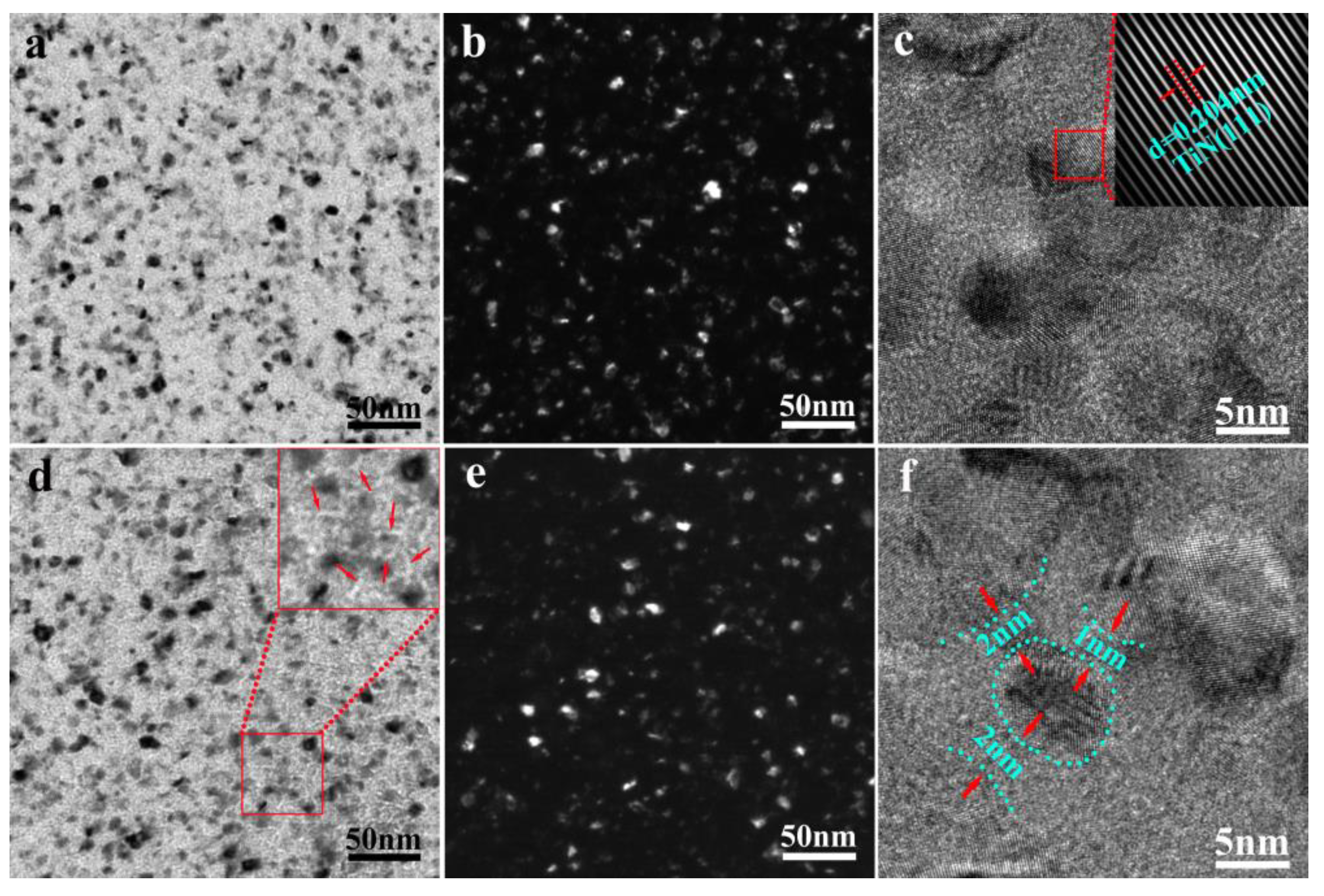
To further determine the presence of Ni in the film, we performed TEM analysis on the film, and the results are shown in Figure 6. It can be seen from Figure 6a,b that the composite film with 4.9 at.% Ni exhibits a nanocrystalline structure. Its grain size is uniform, and the average diameter of the columnar grain is about 10 nm. In the high-resolution image in Figure 6c, the TiN nanocrystals in this film are tightly arranged, and there are no significant excessive regions between most of the grains. This result shows that due to the low content of Ni, most of them are solidly soluble in the crystal lattice of TiN, and a small part exists at the grain boundary in the form of amorphous Ni. The illustration in the upper right corner of Figure 6c is the diffraction pattern corresponding to the red box in the figure. The spacing of its lattice fringes was measured at 0.204 nm, corresponding to the TiN (111) crystal planes. In the film with 12.4 at.% Ni content, a white filamentous structure is observed between the grains, as shown in Figure 6d. The high-resolution image in Figure 6f shows this region to be an amorphous region with a width of 1–2 nm. It shows that the Ni content in this film far exceeds the solid solubility of the TiN lattice. The excess Ni exists amorphously at the grain boundary of the TiN grain, forming a structure of amorphous Ni surrounding the nanocrystalline TiN.
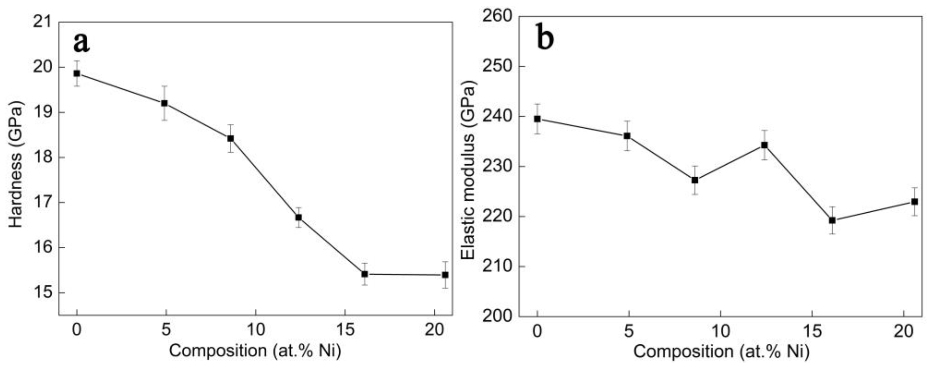
Figure 7 shows the variation of film hardness and elastic modulus with Ni content. The hardness and elastic modulus of the TiN films prepared in this paper are 19.9 GPa and 239.5 GPa, respectively. With the increase in Ni content, the hardness and elastic modulus of the film show a downward trend. When the Ni content is 20.6 at.%, the hardness and elastic modulus are reduced to 15.4 GPa and 223 GPa, respectively. Some existing studies [18,19] of nanocrystalline composite films have shown that the hardness will increase with the addition of alloying elements. However, the alloy content is usually low, e.g., 0.3 at.% Ag in the ZrAgN system [18], 1.5 at.% Ag in the NbAgN [19] system, etc. Once this content range is exceeded, the hardness of the film drops dramatically.
Figure 8a shows the load-indentation depth curve of each film. With the increase in Ni content, the maximum indentation depth gradually increases, indicating that the hardness of the film gradually decreases. In addition, the normalized plastic depth value, δH, which can be used easily and quickly to evaluate the plasticity of the film [20], is also obtained from the load-indentation depth curve. δHhp/hmax, where hp is the indentation depth that cannot be rebounded, and hmax is the maximum indentation depth. In general, the higher the value of δH, the better the toughness of the film. The calculated δH values of films are shown in Figure 8b. With the increase in Ni content, the δH value gradually increases, indicating that the addition of Ni improves the toughness of the TiN film.
Figure 9 shows the OM photographs of the indentation topography of TiN-Ni films with different Ni content under a load of 200 mN. The cracks appear at the triangular vertices of all the sample indentations, and the length of the cracks gradually decreases as the Ni content increases. The fracture toughness ( K I C ) of the film can be calculated using the following formula [21]:
K I C = α E H 0.5 P C m 1.5
where E is the elastic modulus of the film, H is the hardness of the film, P is 200 mN in our paper, C m is the crack length, and α is the empirical constant; its value is 0.016 in our paper.
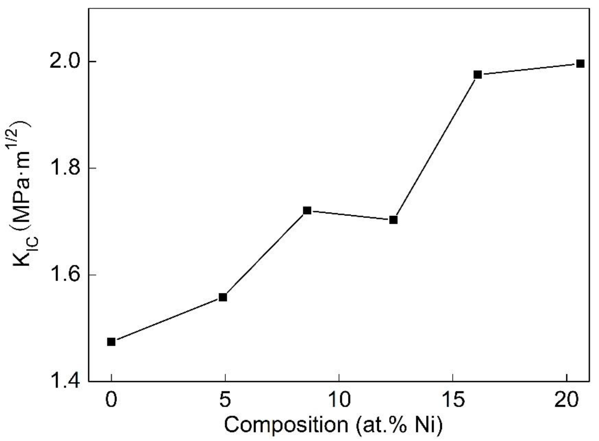
Figure 10 shows the relationship between the fracture toughness ( K I C ) and Ni content of the films. The fracture toughness of the TiN film is about 1.5 MPa·m1/2. With the increase in Ni content, the fracture toughness gradually increases to the highest value of 2.0 MPa·m1/2 at 20.6 at.% Ni.

4. Discussion

4.1. Microstructure

Since being proposed by Musil et al. [8], nc-MeN/soft metal nanocomposites have attracted much research. However, this structure is not easily accessible. For example, Juet al. [22] prepared TiN-Ag nanocomposite films with different Ag content. The results showed that when the Ag content was only 0.7 at.%, Ag nanoparticles appeared in the composite film. When the Ag content increased to 23.5 at.%, the Ag particles were enriched at the TiN grain boundary. Similar phenomena also appear in AlN-Ag [23], AlN-Au [24], and other systems. Wang et al. [25] selected the TiB2-Ni system and prepared TiB2-Ni nanocomposite films with different Ni content. The results show that when the Ni content is 10.8 at.%, the film forms a nanocomposite structure of amorphous Ni-wrapped nanocrystalline TiB2. The above studies show that the choice of system is very important for the formation of nc-MeN/soft metal nanocomposite structures. Further analysis found that the contact angle of Ag to TiN at 1050 °C is 140° [26]. The contact angles of AlN-Ag [27] and AlN-Cu [28] systems at 1000 °C and 1200 °C are 140° and 138°, respectively. The above systems are non-wetting systems. The wettability of Ni to TiB2 is good, and the contact angle at 1500 °C is lower than 50° [29]. Therefore, wettability is a key to the formation of nc-MeN/soft metal nanocomposite structures. The formation of the nc-TiN/Ni nanocomposite structures in this article relies on the good wettability of Ni on TiN ceramics. Some studies have shown that Ni also has good wettability to TiN ceramics [17,30]. The contact angle at 1550 °C is 70°.

4.2. Mechanical Behavior

The research on ZrN-Cu composite film by Musil et al. [8] shows that the formation of nc-ZrN/Cu nanocomposite structure is accompanied by the appearance of superhardness. The highest hardness can reach more than 50 GPa. This phenomenon does not appear in this paper. The hardness of the nc-TiN/Ni nanocomposite structure film is even lower than that of TiN. This result is consistent with the study of the TiB2-Ni system by Wang [25]. The hardness of the nc-TiB2/Ni nanocomposite film is basically the same as that of TiB2, but the toughness is improved by more than 50%. The potential reason for this result is that the Cu content in Musil’s superhard ZrN-Cu nanocomposite films is very low, only 1–2 at.% Cu. The soft metal content in both our TiN-Ni and Wang’s TiB2-Ni nanocomposite films exceeds 10%. Although the excessive soft metal limits the improvement of the hardness, it greatly improves the toughness of the composite film.
In this work, the indentation curves and δH values in Figure 8 and the indentation morphology of Figure 9 show that the toughness of this film is significantly improved. The results in Figure 10 quantitatively provide the fracture toughness of films with different Ni contents. The results indicate that compared to TiN films, the fracture toughness of nc-TiN/Ni nanocomposite films increases by more than 20%. The improvement of film toughness comes from the formation of nanocomposite structures, in which Ni surrounds nanocrystalline TiN. In TiN films, the micro-cracks that initiate around the indentation rapidly expand into macro-cracks once they form. Therefore, the toughness of the film is poor. However, in nc-TiN/Ni nanocomposite films, the micro-cracks initiated in TiN are hindered by the surrounding soft ductile Ni phase. It is difficult for micro-cracks to grow into macro-cracks due to passivation [31] and deflection [32]. The toughness of the film is greatly improved.

5. Conclusions

In order to increase the toughness of TiN, we add Ni elements to TiN using the magnetron sputtering method. The influence of Ni content on the microstructure and mechanical properties of composite films is studied. All the films grow in a columnar crystal structure, and only the TiN crystal phase is presented in the film. The Ni elements mainly exist in the TiN lattice as solid solutions or aggregate at the grain boundaries of TiN as amorphous matter. When the Ni content is 12.4 at.%, the enriched Ni at the TiN grain boundaries is connected into a network. The film forms a nanocomposite structure in which the nanocrystalline TiN grains with a diameter of approximately 15 nm are surrounded by the 1–2 nm thick amorphous Ni phase. The formation of this composite structure depends on the good wettability of Ni to TiN. Compared with pure TiN film, although the hardness of the composite film is slightly reduced, the toughness is greatly improved. The soft and ductile Ni phase enriched at the TiN grain boundaries hinders the propagation of cracks in the TiN phase, resulting in a significant increase in the film’s toughness.

Author Contributions

Conceptualization, B.M. and H.S.; methodology, F.F.; validation, Z.H., Y.H.; formal analysis, B.M.; investigation, H.J.; resources, H.Y.; data curation, B.M.; writing—original draft preparation, Z.H.; writing—review and editing, B.M.; supervision, H.S. All authors have read and agreed to the published version of the manuscript.

Funding

The authors gratefully acknowledge the financial support from the National Natural Science Foundation of China (No. 52002240). CEMMPRE ref. “UIDB/00285/2020” and LA/P/0112/2020 projects, sponsored by FEDER funds through the COMPETE Program Operational Program on Competitiveness Factors and by national funds through the FCT Foundation for Science and Technology, which are also acknowledged.

Institutional Review Board Statement

Not applicable.

Informed Consent Statement

Not applicable.

Data Availability Statement

Not applicable.

Conflicts of Interest

The authors declare no conflict of interest.

References

  1. Bondarev, A.; Al-Rjoub, A.; Yaqub, T.B.; Polcar, T.; Fernandes, F. TEM study of the oxidation resistance and diffusion processes in a multilayered TiSiN/TiN(Ag) coating designed for tribological applications. Appl. Surf. Sci. 2023, 609, 155319. [Google Scholar] [CrossRef]
  2. Tian, C.X.; Wang, Z.S.; Zou, C.W.; Tang, X.S.; Xie, X.; Li, S.Q.; Liang, F.; Li, Z.J.; Liu, Y.F.; Su, F.H. Ternary and quarternary TiBN and TiBCN nanocomposite coatings deposited by arc ion plating. Surf. Coat. Technol. 2019, 359, 445–450. [Google Scholar] [CrossRef]
  3. Wan, Q.; Wu, Z.Y.; Liu, Y.; Yang, B.; Liu, H.D.; Ren, F.; Wang, P.; Xiao, Y.Y.; Zhang, J.; Zhang, G.D. Lead-bismuth eutectic (LBE) corrosion mechanism of nano-amorphous composite TiSiN coatings synthesized by cathodic arc ion plating. Corros. Sci. 2021, 183, 109264. [Google Scholar] [CrossRef]
  4. Wan, Q.; Yang, B.; Chen, Y.M.; Liu, H.D.; Ren, F. Grain size dependence of the radiation tolerances of nano-amorphous Ti-Si-N composite coatings. Appl. Surf. Sci. 2019, 466, 179–184. [Google Scholar] [CrossRef]
  5. Zhou, S.; Zhao, W.; Qiu, Z.; Lin, S.; Zheng, Z.; Zeng, D.C. Improvedload-bearing capacity of Mo-doped Ti-N coatings: Effects of Mo alloying and GB plasticity. Surf. Coat. Technol. 2021, 424, 127630. [Google Scholar] [CrossRef]
  6. Das, C.R.; Rangwala, M.; Ghosh, A. Influence of substrate bias voltage on microstructure and mechanical characteristics of TiAlSiN coating deposited by High Power Impulse Magnetron Sputtering (HiPIMS). Surf. Coat. Technol. 2023, 458, 129351. [Google Scholar] [CrossRef]
  7. Ma, S.L.; Ma, D.Y.; Guo, Y.; Xu, B.; Wu, G.Z.; Xu, K.W.; Chu, P.K. Synthesis and characterization of superhard, self-lubricating Ti–Si–C–N nanocomposite coatings. Acta Mater. 2007, 55, 6350–6355. [Google Scholar] [CrossRef]
  8. Musil, J.; Zeman, P.; Hrubý, H.; Mayrhofer, P.H. ZrN/Cu nanocomposite film—A novel superhard material. Surf. Coat. Technol. 1999, 120–121, 179–183. [Google Scholar] [CrossRef]
  9. Kmar, M.; Mishra, S.; Mitra, R. Effect of Ar:N2 ratio on structure and properties of Ni-TiN nanocomposite thin films processed by reactive RF/DC magnetron sputtering. Surf. Coat. Technol. 2013, 228, 100–114. [Google Scholar] [CrossRef]
  10. Akhter, R.; Bendavid, A.; Munroe, P. Effect of Ni content on the microstructure and mechanical properties of TiNiN coatings. Appl. Surf. Sci. 2022, 573, 151536. [Google Scholar] [CrossRef]
  11. Akhter, R.; Bendavid, A.; Munroe, P. Tailoring the scratch adhesion strength and wear performance of TiNiN nanocompositecoatings by optimizing substrate bias voltage during cathodic arc evaporation. Surf. Coat. Technol. 2022, 445, 128707. [Google Scholar] [CrossRef]
  12. Sahu, B.P.; Ray, M.; Mitra, R. Structure and properties ofNi1-xTixN thin films processed by reactive magnetronco-sputtering. Mater. Charact. 2020, 169, 110604. [Google Scholar] [CrossRef]
  13. Kumar, M.; Mitra, R. Effect of substrate bias on microstructure and properties of Ni-TiN nanocomposite thin films deposited by reactive magnetron co-sputtering. Surf. Coat. Technol. 2014, 251, 239–246. [Google Scholar] [CrossRef]
  14. Akhter, R.; Bendavid, A.; Munroe, P. The influence of substrate bias on the surface morphology, microstructure and mechanical behavior of TiNiN coatings. Appl. Surf. Sci. 2022, 590, 153107. [Google Scholar] [CrossRef]
  15. Irie, M.; Ohara, H.; Tsujioka, M.; Nomura, T. The production and properties ofTiN-Ni nanostructure films by filtered vacuum arc deposition. Mater. Chem. Phys. 1998, 54, 317–320. [Google Scholar] [CrossRef]
  16. Oliver, W.C.; Pharr, G.M. An improved technique or determining hardness and elastic modulus using load and displacement sensing indentation experiments. J. Mater. Res. 2011, 7, 1564–1583. [Google Scholar] [CrossRef]
  17. Denton, A.R.; Ashcroft, N.W. Vegard’s law. Phys. Rev. A 1991, 43, 3161–3164. [Google Scholar] [CrossRef]
  18. Ju, H.; Yu, D.; Yu, L.; Ding, N.; Xu, J.; Zhang, X.; Zheng, Y.; Yang, L.; He, X. The influence of Ag contents on the microstructure, mechanical and tribological properties of ZrN-Ag films. Vacuum 2018, 148, 54–61. [Google Scholar] [CrossRef]
  19. Ren, P.; Zhang, K.; He, X.; Du, S.; Yang, X.; An, T.; Wen, M.; Zheng, W. Toughness enhancement and tribochemistry of the Nb-Ag-N films actuated by solute Ag. Acta Mater. 2017, 137, 1–11. [Google Scholar] [CrossRef]
  20. Milman, Y.V.; Galanov, B.A.; Chugunova, S.I. Plasticity characteristic obtained through hardness measurement. Acta Metall. Mater. 1993, 41, 2523–2532. [Google Scholar] [CrossRef]
  21. Zhang, S.; Zhang, X. Toughness evaluation of hard coatings and thin films. Thin Solid Film. 2012, 520, 2375–2389. [Google Scholar] [CrossRef]
  22. Ju, H.; Yu, L.; Yu, D.; Asempah, I.; Xu, J. Microstructure, mechanical and tribological properties of TiN-Ag films deposited by reactive magnetron sputtering. Vacuum 2017, 141, 82–88. [Google Scholar] [CrossRef]
  23. Domingues, R.P.; Rodrigues, M.S.; Lopes, C.; Pedrosa, P.; Alves, E.; Barradas, N.P.; Borges, J.; Vaz, F. Thin films composed of metal nanoparticles (Au, Ag, Cu) dispersed in AlN: The influence of composition and thermal annealing on the structure and plasmonic response. Thin Solid Film. 2019, 676, 12–25. [Google Scholar] [CrossRef]
  24. Figueiredo, N.M.; Vaz, F.; Cunha, L.; Rodil, S.E.; Cavaleiro, A. Structural, chemical, optical and mechanical properties of Au doped AlN sputtered coatings. Surf. Coat. Technol. 2014, 255, 130–139. [Google Scholar] [CrossRef]
  25. Wang, H.; Wang, B.; Li, S.; Xue, Q.; Huang, F. Toughening magnetron sputtered TiB2 coatings by Ni addition. Surf. Coat. Technol. 2013, 232, 767–774. [Google Scholar] [CrossRef]
  26. Xiao, P.; Derby, B. Wetting of titanium nitride and titanium carbide by liquid metals. Acta Mater. 1996, 44, 307–314. [Google Scholar] [CrossRef]
  27. Taranets, N.Y.; Naidich, Y.V. Wettability of aluminum nitride by molten metals. Powder Metall. Met. Ceram. 1996, 35, 282–285. [Google Scholar]
  28. Wang, C.; Li, S.; Zhang, T.; Pan, Y. The effect of silicon on the wettability and interfacial reaction in AlN/Cu alloy systems. Mater. Sci. Eng. B 2011, 176, 53–59. [Google Scholar] [CrossRef]
  29. Xi, L.; Kaban, I.; Nowak, R.; Bruzda, G.; Sobczak, N.; Eckert, J. Wetting, reactivity, and phase formation at interfaces betweenNi–Al melts and TiB2 ultrahigh-temperature ceramic. J. Am. Ceram. Soc. 2018, 101, 911–918. [Google Scholar] [CrossRef]
  30. Binder, S.; Lengauer, W.; Ettmayer, P. The Ti-N-Ni system: Investigations relevant for cermet sintering. J. Alloys Compd. 1991, 177, 119–127. [Google Scholar] [CrossRef]
  31. Koyama, M.; Zhang, Z.; Wang, M.; Ponge, D.; Raabe, D.; Tsuzaki, K.; Noguchi, H.; Tasan, C.C. Bone-like crack resistance in hierarchical metastable nanolaminate steels. Science 2017, 355, 1055–1057. [Google Scholar] [CrossRef] [PubMed]
  32. Pineau, A.; Benzerga, A.A.; Pardoen, T. Failure of metals I: Brittle and ductile fracture. Acta Mater. 2016, 107, 424–483. [Google Scholar] [CrossRef]
Figure 1. The variation of Ti, Ni, and N contents with Ni target power.
Coatings 13 01902 g001
Figure 2. SEM cross-sectional image of TiN-Ni films with different Ni content: (a) 0 at.% Ni; (b) 8.6 at.% Ni; (c) 12.4 at.% Ni; (d) 16.1 at.% Ni; (e) 20.6 at.% Ni.
Coatings 13 01902 g002
Figure 3. XRD pattern of TiN-Ni nanocomposite films.
Coatings 13 01902 g003
Figure 4. Variation of film grain size with Ni contents.
Coatings 13 01902 g004
Figure 5. The relationship between the intragranular Ni content and the total Ni content of the films.
Coatings 13 01902 g005
Figure 6. TEM bright-field, dark-field, and high-resolution images of films with 4.9 at.% Ni (ac) and 12.4 at.% Ni (df) contents.
Coatings 13 01902 g006
Figure 7. Changes in hardness (a) and elastic modulus (b) of a film with Ni content.
Coatings 13 01902 g007
Figure 8. The load-indentation depth curve (a) and normalized plastic depth (b) of films.
Coatings 13 01902 g008
Figure 9. Optical microscope (OM) photographs of TiN-Ni film indentation with different Ni content:(a) 0 at.% Ni; (b) 4.9at.% Ni; (c) 8.6 at.% Ni; (d) 12.4 at.% Ni; (e) 16.1 at.% Ni; (f) 20.6 at.% Ni.
Coatings 13 01902 g009
Figure 10. Fracture toughness ( K I C ) of thin films as a function of Ni content.
Coatings 13 01902 g010
Disclaimer/Publisher’s Note: The statements, opinions and data contained in all publications are solely those of the individual author(s) and contributor(s) and not of MDPI and/or the editor(s). MDPI and/or the editor(s) disclaim responsibility for any injury to people or property resulting from any ideas, methods, instructions or products referred to in the content.