Article

Oxygen Plasma-Induced Conversion of Silver Complex Ink into Conductive Coatings

1
Beijing Engineering Research Center of Printed Electronics, Beijing Institute of Graphic Communication, Beijing 102600, China
2
Beijing Metro Engineering Management Co., Ltd., Beijing 100010, China
3
Shandong Ruihai New Material Technology Co., Ltd., Zibo 255000, China
4
College of the Environment & Ecology, Xiamen University, Xiamen 361102, China
5
School of Environment, Tsinghua University, Beijing 102600, China
*
Authors to whom correspondence should be addressed.
Coatings 2023, 13(12), 1977; https://doi.org/10.3390/coatings13121977
Submission received: 23 October 2023 / Revised: 14 November 2023 / Accepted: 17 November 2023 / Published: 21 November 2023

Abstract

:
The use of AgNO3-polyvinyl alcohol (PVA) ink and oxygen plasma to form conductive coatings on plastic substrates was studied. It was found that oxygen plasma can decompose silver complexes to form metallic silver without high-temperature heating. The AgNO3-PVA ratio and plasma parameters (time, power) were optimized to obtain uniform conductive coatings. The morphology and electrical characteristics of the coatings were evaluated. Composite coatings with high reflectivity and good adhesion were prepared with a resistivity of 1.66 × 10⁻⁶ Ω·m using MOD inks with a silver ion mass fraction of 5%, after 300 W plasma treatment of the PET substrate for 2 min (the chamber temperature was 37.3 °C). These results demonstrate the potential feasibility of silver MOD inks and oxygen plasma treatment for the production of silver connectors, electromagnetic shielding films, and antimicrobial coatings on low-cost plastic substrates.

1. Introduction

In recent years, additive manufacturing (AM) technology has been popular in many industries because it can produce complex parts at low cost [1]. Additive manufacturing creates coatings for electronic devices that perform important functions. There are many ways to apply coatings using different methods and materials. Coating materials can be metal alloys, ceramics, bio-glass, polymers, and engineering plastics [2]. Among these, metallic materials are widely used in applications such as fuel cells, sensors, field effect devices, surface antimicrobials, and so on [3]. Metallic inks are a good way of using metallic materials in coatings for electronics [4,5,6,7]. They can be used to make many different types of electronic products. To make flexible electronics last longer and work over greater distances, it is important to use inks that are highly homogeneous and conductive. Metallic inks use metal particles or metal precursors as conductive fillers [8]. Metallic inks conduct electricity better than carbon-based materials [9] and conductive polymers [10]. They are often used for printing contacts, interconnects, functional layers, etc. Xie et al. [11] demonstrated fully solution-processed organic thin-film transistors (OTFTs) using silver gate/source/drain fabricated with MOD silver ink. The optimized OTFT exhibited a high field mobility of 0.36 cm2 V−1 s−1 with a threshold voltage of 0.35 V and an on/off current ratio of 1 × 10⁵.
There are two main types of metallic inks: nanoparticle suspension inks and metal–organic decomposition (MOD) inks. MOD inks consist of metals in an ionic state [12,13]. Compared with nanoparticle suspension inks, MOD inks do not have cumbersome processing and stability issues. MOD inks are processed in three simple steps: mixing, printing, and sintering, which greatly reduces the number of manufacturing steps [14,15]. The combination of resistance, price, and stability determines which metal is chosen for MOD inks. Currently, silver is the most commonly used metal due to its moderate price, excellent electrical conductivity, and relatively high oxidation resistance [16,17,18,19,20]. Dong et al. [21] configured a silver MOD ink using silver oxalate, ethylamine, and ethylene glycol. The silver mod ink was printed on a polyimide substrate and cured at 150 °C for 30 min. The thickness of the metalized silver pattern was approximately 1.2 μm, and the resistivity was 8.6 μΩ·cm.
All metallic inks require some form of post-deposition treatment to remove non-metallic components and anneal the metallic structure for optimum electrical properties [4]. Typically, the conversion of MOD inks to their conductive counterparts requires higher temperatures [14]. However, the integration of electronic circuit components onto flexible materials such as plastic films, paper, and textiles is a key challenge for the development of future smart applications. There is therefore a need to deposit conductive metallic features onto temperature-sensitive substrates in a fast and straightforward manner [22]. Plasma processing is used as an industrially viable low-temperature technology in various fields, including materials science [23,24]. It has great potential in the field of additive manufacturing, such as surface modification of substrates [25] and post-deposition annealing of nanoparticle structures [26]. Hydrogen plasma treatment of copper MOD inks was demonstrated by Kwon et al. [27]. As the gases of highly reactive substances contain ions, electrons, substable neutrals, and free radicals [28,29,30,31], they can be easily exchanged with the elements, thus providing sufficient energy for reduction and sintering [32]. The low-temperature plasma process paves the way for MOD inks to be used in the manufacture of silver connectors, arrays, electronics, etc., on low-cost polymer substrates using printing processes such as R2R processing, inkjet printing, and 3D manufacturing.
In this study, we present a new method using AgNO3 and PVA as precursors and complexing ligands, respectively, which are dissolved in water to form silver MOD inks, and then the silver complex is decomposed by oxygen plasma to form metallic silver. This method allows rapid preparation of conductive coatings at temperatures below 70 °C in a few minutes. We optimized the AgNO3-PVA ratio and plasma parameters (time, power) to obtain uniform and dense conductive coatings. The morphology and electrical properties of the coatings were evaluated. We believe that low-temperature plasma deposition of conductive coatings has broad applications in electromagnetic shielding films and antimicrobial coatings.

2. Materials and Methods

2.1. Material

Poly (vinyl alcohol) (PVA, 88,000 g/mol, degree of polyvinyl acetate hydrolysis at 98.5–99.4 mol%) was purchased from Shanghai Macklin Biochemical Technology Co. of China (Shanghai, China). Sliver nitrate (AgNO3, 99.8%) was purchased from Beijing Chemical Factory (Beijing, China). Water was deionized prior to use.

2.2. Preparation of AgNO3-PVA and the Plasma Process

An amount of PVA was added to deionized water, heated to 80 °C, and stirred until completely dissolved to form a 10 ωt% solution of PVA. Then, a certain amount of AgNO3 was weighed and dissolved in deionized water at room temperature. In the case of keeping the mass fraction of PVA constant, 3.0 g of PVA solution was taken, and the mass of silver nitrate was varied so that the silver ions and PVA had different mass ratios of 0.5:1, 0.75:1, 1:1, 1.25:1, and 1.5:1. In the configuration of a total mass of 6 g of AgNO3-PVA solution, PVA accounted for 5% of the total mass, and AgNO3 accounted for a mass fraction in the order of 2.5 ωt% to 7.5 ωt%. The PET used as a substrate was washed with ethanol before coating. Using a four-sided preparer, one side was selected with a thickness of 5 um, and AgNO3-PVA ink was applied to the PET substrate at a uniform speed. After coating, it was dried at a constant temperature of 30 °C, which is the pre-drying process.
A low-temperature plasma processor (SY-DT02S, OPS Plasma Technology Co., Ltd., Suzhou, China), which is capacitively coupled plasma (CCP), was used in the experiments. The initial electrons in the reaction chamber were energized with the RF electric field and bombarded the oxygen to ionize it, generating more electrons, ions, and neutral radical particles to form a dynamically balanced cryogenic plasma. The pre-dried AgNO3-PVA coating was placed in the reaction chamber with the oxygen flux set to 30 SCCM and the background vacuum set to 20 Pa. The coating was processed using different powers (100 W, 300 W, and 500 W) and different times (0.5 min, 1 min, 1.5 min, 2 min, 3 min, 4 min, 5 min, 6 min, 7 min, and 8 min). Before each sample treatment, care was taken to control the temperature of the chamber close to room temperature to reduce experimental errors.

2.3. Measurements and Instruments

A confocal laser scanning microscope (VK-X250, KEYENCE (China) Co., Ltd., Shanghai, China) was acquired for observing the coating morphology before and after plasma treatment. An infrared thermometer was used to measure the plasma chamber temperature after sample removal. UV-Vis spectrophotometer (Cary 100, Agilent Technologies (China) Co., Ltd., Beijing, China) was used for the determination of Ag+-PVA complexation at different mass ratios. A scanning electron microscope ( SU8020, Hitachi High-Tech (Shanghai) Co., Ltd., Shanghai, China) was used to observe the surface morphology and cross-section of the coatings after treatment at different powers and times.
X-ray photoelectron spectroscopy (Thermo escalab 250Xi, Thermo Fisher Scientific, Waltham, MA, USA) was used to probe the state of the silver on the surface of the coatings, using a monochromatic Al Kα ray source (hv =1486.6 eV) with a power of 150 W, a 650 um beam spot, a voltage of 14.8 KV, and a current of 1.6 A. Charge correction was performed using contaminated carbon C1s =284.8 eV for correction, and peak fitting for component analysis was performed using Gaussian–Lorentzian curves.
To investigate the electrical conductivity of the coatings under plasma treatment, the sheet resistance Rs at uniformly thin layers was tested using a four-probe tester (RTS-9, 4Probes Tech Ltd., Guangzhou, China) with an average probe spacing of S = 1 mm and a correction factor C = 6.28.

3. Results

3.1. Preparation of Conductive Coating

In this study, conductive coatings were prepared with oxygen plasma treatment, including coating, pre-drying, and oxygen plasma treatment. In oxygen plasma in the presence of an electric field, oxygen molecules are ionized. The ionized oxygen ions collide with external electrons and recombine into chemical constituents such as free radicals or molecules. At this point, the electrons, radicals, ions, and neutral molecules also interact and collide as a result of the collisions and reactions between the plasma components. This creates a very active system of chemical–physical reactions. The overall process scheme is shown in Figure 1, starting from the coating of AgNO3-PVA ink on polyethylene glycol terephthalate (PET). After pre-drying, the AgNO3-PVA coating is treated with plasma to decompose the ligand, accompanied by intramolecular silver reduction, nucleation, and crystal growth, which eventually forms a continuous silver metallic coating.

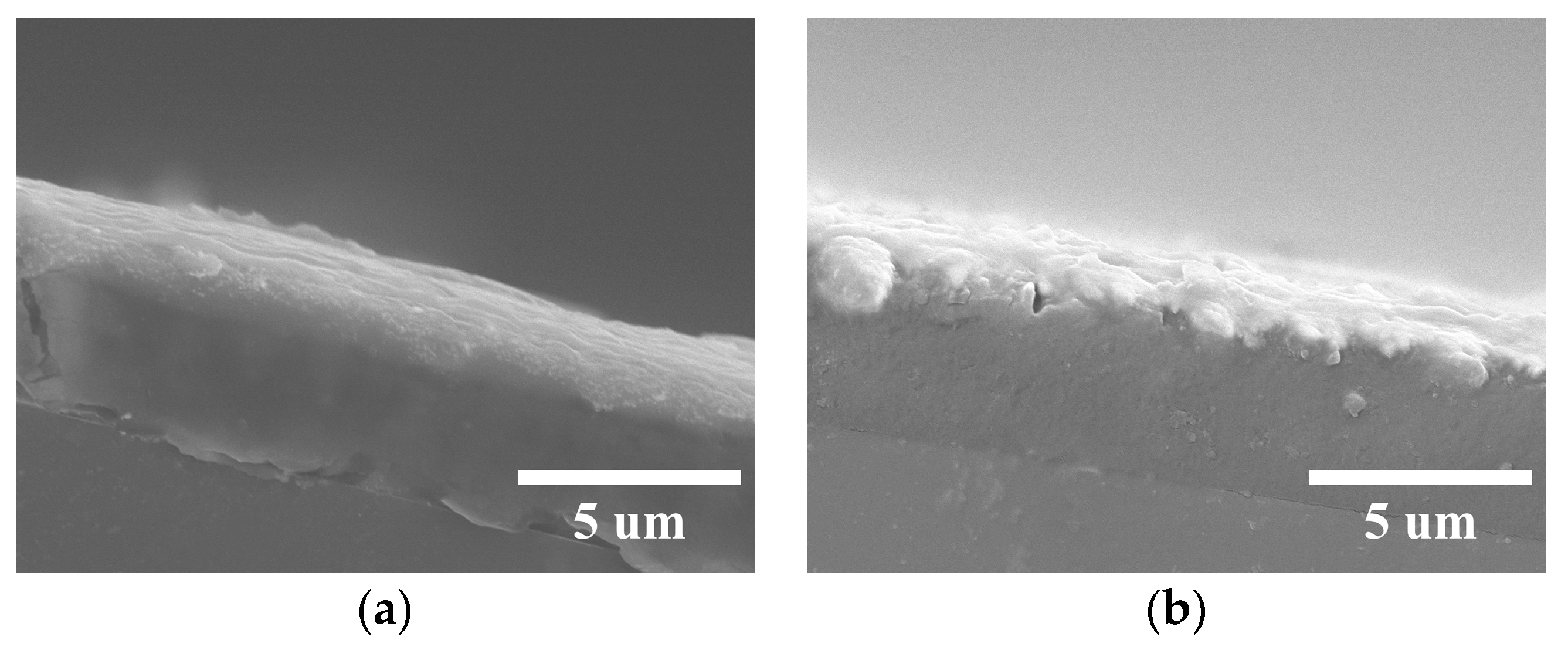
3.2. XPS of Conductive Coatings and Surface Morphology

The conversion of the silver complex into metallic silver at different powers was studied using XPS measurements. As shown in Figure 2a, before the plasma treatment, only the characteristic peaks of C (1s) and O (1s) were detected. After plasma treatment, the intensity of C (1s) and O (1s) peaks were significantly decreased, and the characteristic peak of Ag (3d) appeared. The XPS surface spectra of the untreated coating did not show the characteristic Ag (3d) peak. It was hypothesized that this could be due to the formation of a coordination bond between the hydroxyl group on the side of the PVA and the silver ions, with the PVA ‘wrapping’ the silver ions. At the same time, silver ions were not detected due to the limited detection range of XPS. After plasma treatment, for example, at 100 W, part of the ligands decomposed, the amount of carbon and oxygen was reduced, and silver ions were exposed and detected.
The coating surface’s silver chemical state varies with different plasma powers, as seen in Figure 2b. At 100 W, the binding energy of Ag (3d5/2) is 368.74 eV, which is close to the binding energy value of silver nitrate of 368.8 eV in the literature [33]. At 300 W and 500 W, the binding energy of Ag (3d5/2) is in the vicinity of Ag0 (368.20 eV) [34]. The Ag (MNN) Auger spectra at different powers were then compared, as shown in Figure 2c. With an increase in power, the displacement of the Auger peak of the detected Ag on the film surface from the Auger peak of Ag0 [35] is smaller, i.e., the change in the state of Ag during the conversion of AgNO3 into Ag is more obvious. The Auger parameter is the sum of binding and kinetic energies. And according to the literature, the Auger parameters for Ag0 are 726.0 eV (M4NN) and 720.5 eV (M5NN) [36]. For the silver layer obtained with treatment at 500 W power, the Auger parameters 725.23 eV (M4NN) and 719.72 eV (M5NN) were obtained according to the calculations, with a maximum difference of 0.78 eV from the literature values.
To further clarify the state of the silver, we analyze the production of silver oxides in conjunction with the state of O (1s). As shown in Figure 2d, the characteristic peaks of metal oxides (530 eV) [37] do not appear in the O (1s) spectra, so there are no silver oxides present. The reason for the large difference in Auger parameters should be that a small portion of Ag+ is still present and unreduced in the coating. Combined with Figure 2e, the total C (1s) content of the coating surface decreases, but the content of O-C=O in it increases, which echoes the increase in O (1s). Combining the literature [5,38,39] and experimental results, we believe that the reactive oxygen in the oxygen plasma reacts with the organic matter on the surface of the coating, resulting in the breakage of the PVA polymer chains and further oxidation. This decomposition leads to the transfer of intramolecular electrons from ligands to metal ions, contributing to the reduction of silver ions to Ag0. At the same time, increasing the power for the same treatment time helps the reduction of silver ions.
The details of the interaction of PVA with Ag species were investigated using a confocal laser scanning microscope (CLSM) for PVA itself and AgNO3-PVA at a 1:1 weight ratio under different treatment times, as shown in Figure 3. Coating with the PVA solution, as shown in Figure 3a, produced uniform and smooth coatings. Whereas, in Figure 3b, the AgNO3-PVA coating produced a fern-like [40] morphology after solvent drying at room temperature. PVA has multiple side hydroxyl groups that are able to form ligand bonds with Ag+ through the electron-donating function of the hydroxyl groups. When the solvent evaporated, silver ions were further stabilized by the PVA matrix. The dried AgNO3-PVA coating was subjected to plasma treatment for 0.5 min, and the fern-like morphology was found to remain unchanged (Figure 3c). At the same power, the treatment time of AgNO3-PVA coatings was extended to 1 min, 2 min, and 4 min, as shown in Figure 3d–f. With the increase in time, the fern-like morphology disappeared and eventually fused into an interconnected silver coating. In Figure 3c,d, there are obvious black dots (marked with black boxes), which may be caused by the coating being contaminated with dust-like impurities during the coating or drying process.

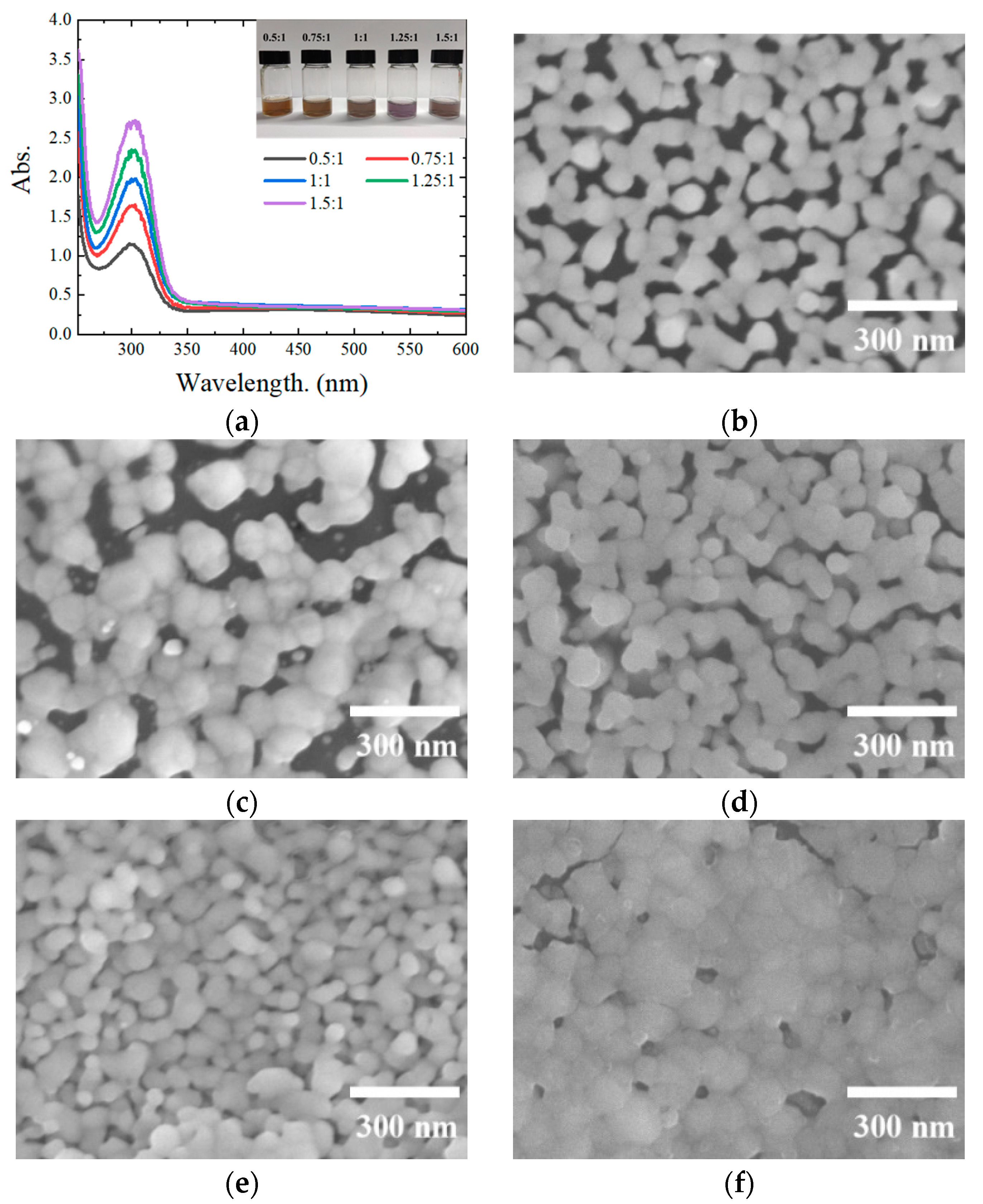
3.3. Effect of the AgNO3 Ratio on the Conductive Coating

The formation of silver substances on the surface of Ag-PVA films at different ratios was investigated. Figure 4a shows the UV spectra of AgNO3-PVA solutions with different mass ratios, and the inset shows their optical pictures. First, the solutions with different ratios were injected into a quartz cuvette. Then, the PVA solution with a 5% mass fraction was diluted the same number of times as the blank reagent. M(PVA) was fixed, and the absorption intensity of the complex system showed an enhanced tendency with the increase in m(Ag+). Scanning electron microscopy was used to study the formation of Ag NPs on different coatings. Figure 4b–f shows the surface morphology of AgNO3-PVA coatings with selected ratios (m(Ag+):m(PVA) = 0.5:1, 0.75:1, 1:1, 1.25:1, 1.5:1) after plasma treatment for 2 min at 300 W, providing direct evidence of Ag nanoparticle aggregation. When the silver ion ratio was low (e.g., 0.5:1 for AgNO3-PVA), only relatively dispersed Ag nanoparticles were observed on the surface of the films (Figure 4b), while the composite films showed no electrical conductivity. The ratio was increased to 0.75:1-1:1, as shown in Figure 4c,d. The 1:1 ratio produced larger nanoparticles than the 0.75:1 ratio. With increasing m(Ag+), the particle size tended to increase, and the shape became more and more irregular. When the Ag ion content exceeded 1:1, as shown in Figure 4e, individual irregularly shaped silver clusters appeared due to the lack of dispersing ability of PVA to protect the Ag nanoparticles from aggregation. As the Ag content continued to increase, the Ag nanoparticles eventually fused into an interconnected morphology (Figure 4f).

3.4. Growth Mechanisms

In order to elucidate the formation mechanism of the conductive coatings, SEM images of the cross-sections of the coatings were obtained at different processing times with the same power, as shown in Figure 5. The plasma treatment process is a surface treatment, so the whole coating shows a layered structure after the plasma treatment, and the reduced Ag NPs are distributed only on the surface of the coating. The cross-sectional morphology of the coating obtained by processing at 300 W for 2 min is shown in Figure 5b, and the thickness of the reduced silver layer is about 0.8 μm. The cross-sectional morphology of the coating obtained by processing at 300 W for 0.5 min is shown in Figure 5a. As the treatment time increases, the particle size also increases due to the aggregation of the Ag NPs.
According to the CLSM, XPS, and SEM analyses, the plasma-prepared conductive coatings underwent three stages, including pre-drying to form a fern-like morphology, reduction to Ag NPs, and aggregation of Ag NPs. As shown in Figure 6, firstly, after water evaporation at 30 °C, the interaction between AgNO3 and PVA hydroxyl groups occurred and Ag+ was stabilized by the PVA matrix. Secondly, with plasma treatment, the ligand decomposes while Ag+ reduces to Ag0, gradually generating Ag NPs. Thirdly, with the prolongation of the treatment time, Ag NPS polymerized and thus formed a silver network. Oxygen plasma induced MOD inks to generate metal, providing an effective method for pre-paring high conductivity coatings.

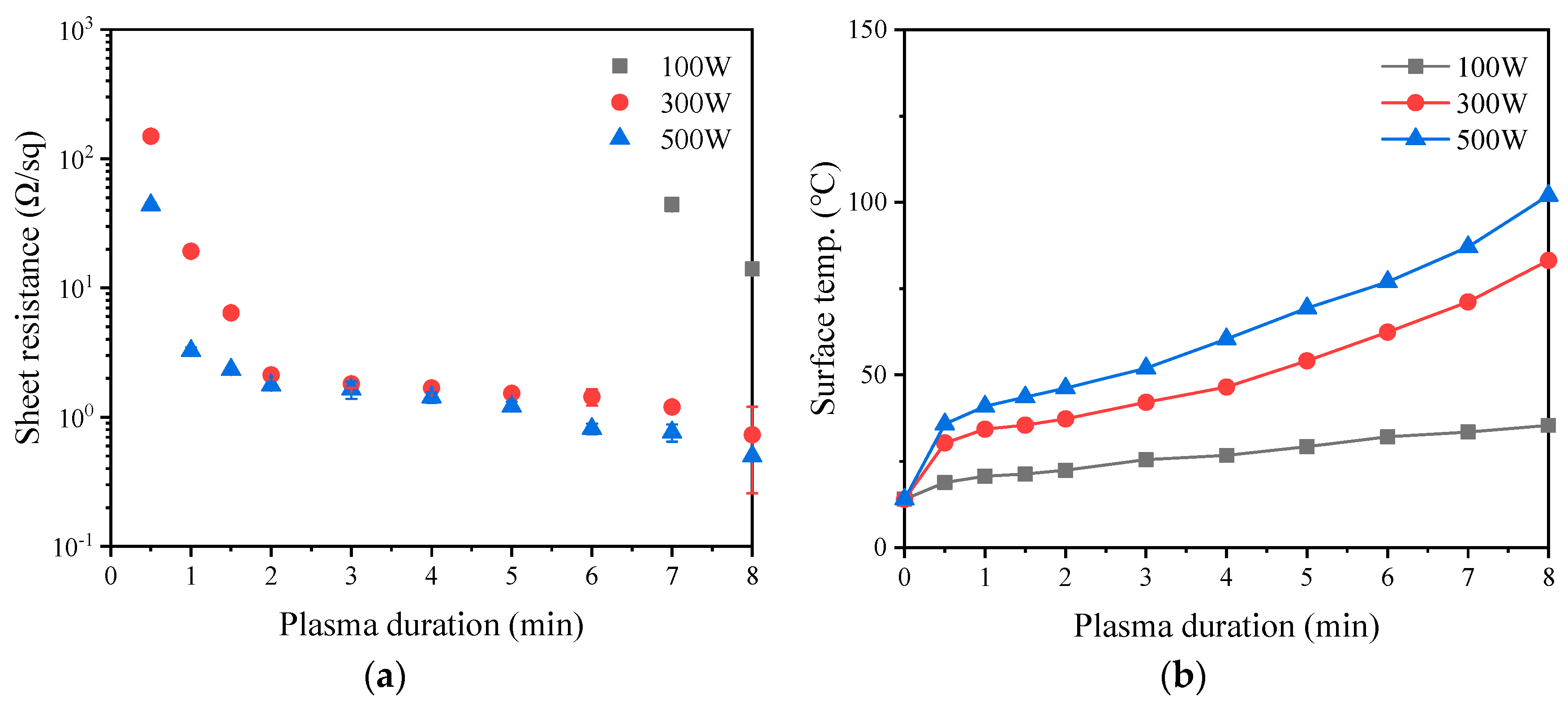
3.5. Conductive Properties of Coatings

In order to improve electrical conductivity, further studies were carried out by varying the plasma duration and power. As shown in Figure 7a, a series of sheet resistances was obtained from AgNO3-PVA (1:1) coatings with a thickness of 5 μm under different treatment conditions. At 100 W, the resistance of the coating plummeted to reflect the electrical conductivity after 7 min of continuous treatment. Combined with the previous analyses in Figure 2b,c, it can be found that at low power, the electrons generated by ligand decomposition are not sufficient at this time to reduce most of the Ag+ to Ag0 rapidly due to the low plasma density and active particle energy [14,41,42]. At 300 W and 500 W, the sheet resistance decreases sharply with time. At a certain time, the higher the power, the faster the value of sheet resistance decreases. With the increase in processing time, the decreasing trend in the resistance value slows down, and the resistance value converges.
The temperature corresponding to the plasma chamber after the process treatment was also recorded. As shown in Figure 7b, the temperature was positively correlated with the plasma treatment time and power. At 300 W and 500 W, the fastest decrease in resistance value was observed at t = 2 min (2.13 ± 0.16 Ω/sq) and t = 1 min (3.26 ± 0.20 Ω/sq), which corresponded to temperatures of 37.3 °C and 40.9 °C, respectively. Combined with the cross-sectional SEM images of the composite coatings, the resistivity of the composite coatings can be estimated to be 166.4 μΩ·cm after 2 min treatment at 300 W. Given the low thermoforming temperature of the PET substrate, the composite film resistance can reach a minimum of 1.44 ± 0.20 Ω/sq under the premise of keeping the substrate from deformation. According to Table 1, the low-temperature oxygen plasma-prepared conductive coatings have a great advantage in terms of treatment temperature and treatment time compared with other research, but it is obvious that there is still a lot of room for manipulation in terms of reducing the resistivity.
Figure 8a shows that the conductive coating treated at 300 W power for 2 min has good bending properties, and with a metallic sheen on the surface of the coating.. In addition, a simple tape test was performed to check the adhesion of the coating, as shown in Figure 8b. After first scribing a grid on the coating with a pug knife and then removing the attached tape (600 tape, 3 M), the coating was completely retained on the PET substrate, indicating good adhesion of the coating. Connected to a circuit, the coating caused the light bulb to glow (Figure 8c).

4. Conclusions

In summary, a new method for the production of conductive coatings on flexible plastic substrates is proposed. The method is based on the use of low-temperature plasma-induced decomposition of MOD ink. The ink was synthesized with a complexation reaction of PVA and silver nitrate in water. The conductive coating was prepared with oxygen plasma treatment of an AgNO3-PVA coating on a PET substrate, in which silver ions were reduced to Ag NPs and aggregated. The PET substrate was treated with 300 W plasma for 2 min using MOD ink with a silver ion mass fraction of 5%, and the chamber temperature after treatment was 37.3 °C. A composite coating with a resistivity of 1.66 × 10⁻⁶ Ω·m, high reflectivity, and good adhesion was finally obtained. These results provide the basis for our group to further explore the application of this conductive coating in electromagnetic shielding films and antimicrobial coatings.

Author Contributions

Conceptualization, M.C., X.S. and T.W.; methodology, M.C., X.S. and T.W.; software, J.Y., Y.Q. and L.L.; validation, J.Y. and X.G.; investigation, S.L., J.Y. and X.G.; resources, Y.Q. and L.L.; writing—original draft preparation, S.L.; writing—review and editing, S.L.; visualization, X.G., X.S. and T.W.; supervision, M.C., H.Z. and M.S.; project administration, M.C.; funding acquisition, M.C. All authors have read and agreed to the published version of the manuscript.

Funding

This research was supported by the National Key R&D Program “Intergovernmental International Science and Technology Innovation Cooperation Project” (2023YFE0113800), the National Natural Science Foundation of China (61971049, 22278037), the Key Scientific Research Project of Beijing Municipal Commission of Education (KZ202110015019), and the China–Czech 43th INTER-GOVERNMENTAL S&T COOPERATION PROGRAM G 43-7.

Institutional Review Board Statement

Not applicable.

Informed Consent Statement

Not applicable.

Data Availability Statement

Data are contained within the article.

Conflicts of Interest

The authors declare that the research was conducted in the absence of any commercial or commercial or financial relationships that could be construed as a potential conflict of interest.

References

  1. Gipperich, M.; Riepe, J.; Day, R.; Bergs, T. Express wire coil cladding as an advanced technology to accelerate Additive Manufacturing and coating. J. Eng. Gas Turbines Power 2022, 144, 021003. [Google Scholar]
  2. Fotovvati, B.; Namdari, N.; Dehghanghadikolaei, A. On coating techniques for surface protection: A review. J. Manuf. Mater. Process. 2019, 3, 28. [Google Scholar]
  3. Mohanty, S.; Gokuldoss Prashanth, K. Metallic coatings through additive manufacturing: A review. Materials 2023, 16, 2325. [Google Scholar] [PubMed]
  4. Bromberg, V.; Ma, S.; Egitto, F.D.; Singler, T.J. Highly conductive lines by plasma-induced conversion of inkjet-printed silver nitrate traces. J. Mater. Chem. C 2013, 1, 6842. [Google Scholar]
  5. Farraj, Y.; Smooha, A.; Kamyshny, A.; Magdassi, S. Plasma-induced decomposition of copper complex ink for the formation of highly conductive copper tracks on heat-sensitive substrates. ACS Appl. Mater. Interfaces 2017, 9, 8766–8773. [Google Scholar] [CrossRef]
  6. Farraj, Y.; Grouchko, M.; Magdassi, S. Self-reduction of a copper complex MOD ink for inkjet printing conductive patterns on plastics. Chem. Commun. 2015, 51, 1587–1590. [Google Scholar]
  7. Douglas, S.P.; Knapp, C.E. Low-temperature deposition of highly conductive aluminum metal films on flexible substrates using liquid alane MOD precursors. ACS Appl. Mater. Interfaces 2020, 12, 26193–26199. [Google Scholar] [CrossRef]
  8. Cano-Raya, C.; Denchev, Z.Z.; Cruz, S.F.; Viana, J.C. Chemistry of solid metal-based inks and pastes for printed electronics—A review. Appl. Mater. Today 2019, 15, 416–430. [Google Scholar]
  9. Hu, G.; Kang, J.; Ng, L.W.; Zhu, X.; Howe, R.C.; Jones, C.G.; Hersam, M.C.; Hasan, T. Functional inks and printing of two-dimensional materials. Chem. Soc. Rev. 2018, 47, 3265–3300. [Google Scholar]
  10. Wang, Y.; Zhu, C.; Pfattner, R.; Yan, H.; Jin, L.; Chen, S.; Molina-Lopez, F.; Lissel, F.; Liu, J.; Rabiah, N.I.; et al. A highly stretchable, transparent, and conductive polymer. Sci. Adv. 2017, 3, e1602076. [Google Scholar]
  11. Xie, Y.; Ouyang, S.; Wang, D.; Lee, W.-Y.; Fong, H.H. Highly smooth and conductive silver film with metallo-organic decomposition ink for all-solution-processed flexible organic thin-film transistors. J. Mater. Sci. 2020, 55, 15908–15918. [Google Scholar] [CrossRef]
  12. Zhao, P.; Huang, J.; Nan, J.; Liu, D.; Meng, F. Laser sintering process optimization of microstrip antenna fabricated by inkjet printing with silver-based MOD ink. J. Mater. Process. Technol. 2020, 275, 116347. [Google Scholar] [CrossRef]
  13. Yang, Y.; Liu, D.; Zhao, P.; Huang, J. Effect of processing parameters on laser sintering of silver MOD inks for inkjet printing. IET Collab. Intell. Manuf. 2019, 1, 10–19. [Google Scholar] [CrossRef]
  14. Choi, Y.; Seong, K.; Piao, Y. Metal–organic decomposition ink for printed electronics. Adv. Mater. Interfaces 2019, 6, 1901002. [Google Scholar] [CrossRef]
  15. Zope, K.R.; Cormier, D.; Williams, S.A. Reactive silver oxalate ink composition with enhanced curing conditions for flexible substrates. ACS Appl. Mater. Interfaces 2018, 10, 3830–3837. [Google Scholar] [CrossRef]
  16. Bai, Y.; Williams, C.B. Binder jetting additive manufacturing with a particle-free metal ink as a binder precursor. Mater. Des. 2018, 147, 146–156. [Google Scholar] [CrossRef]
  17. Yang, W.; Wang, C.; Arrighi, V. Silver oxalate ink with low sintering temperature and good electrical property. J. Electron. Mater. 2018, 47, 2824–2835. [Google Scholar] [CrossRef]
  18. Rosker, E.S.; Barako, M.T.; Nguyen, E.; DiMarzio, D.; Kisslinger, K.; Duan, D.-W.; Sandhu, R.; Goorsky, M.S.; Tice, J. Approaching the practical conductivity limits of aerosol jet printed silver. ACS Appl. Mater. Interfaces 2020, 12, 29684–29691. [Google Scholar] [CrossRef]
  19. Zhong, T.; Jin, N.; Yuan, W.; Zhou, C.; Gu, W.; Cui, Z. Printable stretchable silver ink and application to printed RFID tags for wearable electronics. Materials 2019, 12, 3036. [Google Scholar] [CrossRef]
  20. Vaseem, M.; McKerricher, G.; Shamim, A. Robust Design of a Particle-Free Silver-Organo-Complex Ink with High Conductivity and Inkjet Stability for Flexible Electronics. ACS Appl. Mater. Interfaces 2016, 8, 177–186. [Google Scholar] [CrossRef]
  21. Dong, Y.; Li, X.; Liu, S.; Zhu, Q.; Li, J.G.; Sun, X. Facile synthesis of high silver content MOD ink by using silver oxalate precursor for inkjet printing applications. Thin Solid Film. 2015, 589, 381–387. [Google Scholar] [CrossRef]
  22. Marchal, W.; Vandevenne, G.; D’Haen, J.; de Andrade Almeida, A.C.; Sola, M.D.; Van Den Ham, E.J.; Drijkoningen, J.; Elen, K.; Deferme, W.; Van Bael, M.K.; et al. Ultrasonically spray coated silver layers from designed precursor inks for flexible electronics. Nanotechnology 2017, 28, 215202. [Google Scholar] [CrossRef]
  23. Machala, Z.; Graves, D.B. Frugal biotech applications of low-temperature plasma. Trends Biotechnol. 2018, 36, 579–581. [Google Scholar] [CrossRef]
  24. Akayeti, A.; Zhang, W.; Yan, X.; Wang, Q. Low-temperature oxygen plasma treatment of single-layer molybdenum disulfide. Mater. Res. Express 2019, 6, 055007. [Google Scholar] [CrossRef]
  25. Adusei, P.K.; Gbordzoe, S.; Kanakaraj, S.N.; Hsieh, Y.Y.; Alvarez, N.T.; Fang, Y.; Johnson, K.; McConnell, C.; Shanov, V. Fabrication and study of supercapacitor electrodes based on oxygen plasma functionalized carbon nanotube fibers. J. Energy Chem. 2020, 40, 120–131. [Google Scholar] [CrossRef]
  26. Turan, N.; Saeidi-Javash, M.; Chen, J.; Zeng, M.; Zhang, Y.; Go, D.B. Atmospheric pressure and ambient temperature plasma jet sintering of aerosol jet printed silver nanoparticles. ACS Appl. Mater. Interfaces 2021, 13, 47244–47251. [Google Scholar] [CrossRef] [PubMed]
  27. Kwon, Y.-T.; Lee, Y.-I.; Kim, S.; Lee, K.-J.; Choa, Y.-H. Full densification of inkjet-printed copper conductive tracks on a flexible substrate utilizing a hydrogen plasma sintering. Appl. Surf. Sci. 2017, 396, 1239–1244. [Google Scholar] [CrossRef]
  28. Huang, Y.; Yu, Q.; Li, M.; Jin, S.; Fan, J.; Zhao, L.; Yao, Z. Surface modification of activated carbon fiber by low-temperature oxygen plasma: Textural property, surface chemistry, and the effect of water vapor adsorption. Chem. Eng. J. 2021, 418, 129474. [Google Scholar] [CrossRef]
  29. Shi, Q.; Vitchuli, N.; Nowak, J.; Caldwell, J.M.; Breidt, F.; Bourham, M.; Zhang, X.; McCord, M. Durable antibacterial Ag/polyacrylonitrile (Ag/PAN) hybrid nanofibers prepared by atmospheric plasma treatment and electrospinning. Eur. Polym. J. 2011, 47, 1402–1409. [Google Scholar] [CrossRef]
  30. Jelil, R.A. A review of low-temperature plasma treatment of textile materials. J. Mater. Sci. 2015, 50, 5913–5943. [Google Scholar]
  31. Wang, L.; Wang, W.; Zhao, H.; Liu, Y.; Liu, J.; Bai, N. Bioactive effects of low-temperature argon–oxygen plasma on a titanium implant surface. ACS Omega 2020, 5, 3996–4003. [Google Scholar] [CrossRef] [PubMed]
  32. Knapp, C.E.; Chemin, J.B.; Douglas, S.P.; Ondo, D.A.; Guillot, J.; Choquet, P.; Boscher, N.D. Room-Temperature Plasma-Assisted Inkjet Printing of Highly Conductive Silver on Paper. Adv. Mater. Technol. 2018, 3, 1700326. [Google Scholar] [CrossRef]
  33. Contreras-Arzate, D.; Islas-Espinoza, M.; Fall, C.; Alcántara-Díaz, D.; Olguin, M.T.; López-Callejas, R.; Peña-Eguiluz, R. Microbial mortality behavior promoted by silver (Ag+/Ago)-modified zeolite-rich tuffs for water disinfection. J. Environ. Health Sci. Eng. 2020, 18, 755–768. [Google Scholar] [CrossRef]
  34. Bolli, E.; Mezzi, A.; Burratti, L.; Prosposito, P.; Casciardi, S.; Kaciulis, S. X-ray and UV photoelectron spectroscopy of Ag nanoclusters. Surf. Interface Anal. SIA 2020, 52, 1017–1022. [Google Scholar] [CrossRef]
  35. Ferraria, A.M.; Carapeto, A.P.; do Rego, A.M.B. X-ray photoelectron spectroscopy: Silver salts revisited. Vacuum 2012, 86, 1988–1991. [Google Scholar] [CrossRef]
  36. Li, S.; Cai, K.; Li, Y.; Liu, S.; Yu, M.; Wang, Y.; Ma, X.; Huang, S. Identifying the active silver species in carbonylation of dimethyl ether over Ag−HMOR. ChemCatChem 2020, 12, 3290–3297. [Google Scholar] [CrossRef]
  37. Idriss, H. On the wrong assignment of the XPS O1s signal at 531–532 eV attributed to oxygen vacancies in photo- and electro-catalysts for water splitting and other materials applications. Surf. Sci. 2021, 712, 121894. [Google Scholar] [CrossRef]
  38. Khelifa, F.; Ershov, S.; Habibi, Y.; Snyders, R.; Dubois, P. Free-radical-induced grafting from plasma polymer surfaces. Chem. Rev. 2016, 116, 3975–4005. [Google Scholar] [CrossRef]
  39. Elashry, S.; ELsaeed, H.; El-Siragy, N.M. Microwave plasma discharge-assisted surface modification of PVA films: Coatings and food packaging. Eur. Phys. J. Plus 2022, 137, 1252. [Google Scholar] [CrossRef]
  40. Liang, K.-L.; Wang, Y.-C.; Lin, W.-L.; Lin, J.-J. Polymer-assisted self-assembly of silver nanoparticles into interconnected morphology and enhanced surface electric conductivity. RSC Adv. 2014, 4, 15098. [Google Scholar] [CrossRef]
  41. Huang, X.; Wang, S.; Wu, J.; Dai, L.; Li, L.; Guo, Y.; Zhang, J.; Shi, J. Characterization of atmospheric-pressure helium–oxygen dual-frequency glow discharges using optical emission spectroscopy. IEEE Transactions on Plasma Science. IEEE Nucl. Plasma Sci. Soc. 2019, 47, 1788–1792. [Google Scholar] [CrossRef]
  42. Xiao, D.; Bao, D.L.; Liang, X.; Wang, Y.; Shen, J.; Cheng, C.; Chu, P.K. Experimental and theoretical investigation of the control and balance of active sites on oxygen plasma-functionalized MoSe2 nanosheets for efficient hydrogen evolution reaction. Appl. Catal. B Environ. 2021, 288, 119983. [Google Scholar] [CrossRef]
  43. Wu, J.-T.; Hsu, S.L.-C.; Tsai, M.-H.; Hwang, W.-S. Inkjet printing of low-temperature cured silver patterns by using AgNO3/1-dimethylamino-2-propanol inks on polymer substrates. J. Phys. Chem. C Nanomater. Interfaces 2011, 115, 10940–10945. [Google Scholar] [CrossRef]
  44. Nie, X.; Wang, H.; Zou, J. Inkjet printing of silver citrate conductive ink on PET substrate. Appl. Surf. Sci. 2012, 261, 554–560. [Google Scholar] [CrossRef]
Figure 1. Scheme representing the preparation of continuous conductive coatings with oxygen plasma and the physicochemical processes of the coatings.
Coatings 13 01977 g001
Figure 2. (a) XPS surface spectra of coatings without plasma treatment and plasma-treated coatings at different powers. (b) Spectra of Ag (3d) at different powers, with chemical shifts with power enhancement. The solid lines in the figure indicate the binding energies of Ag (3d3/2) and Ag (3d5/2) for Ag0. (c) Spectra of Ag (MNN) at different powers, with a shift in the Ag Auger peak to Ag0 with power enhancement. The solid lines in the figure indicate where the Ag (M5NN) and Ag (M4NN) Auger peaks of Ag0 are located. (d) Spectra of O (1s) at 300 W and 500 W, with no characteristic metal oxide peaks appearing. At the same time, the organic oxygen component increases. The solid line in the graph indicates where the characteristic peaks of the metal oxides are located. (e) C (1s) spectra at 300 W and 500 W, with a decrease in the total C content and an increase in the O-C=O content.
Coatings 13 01977 g002
Figure 3. Conversion of silver complexes to metallic silver as a function of oxygen plasma treatment time. Untreated (a) PVA coating and (b) AgNO3-PVA coating treated at 300 W for (c) 0.5 min, (d) 1 min, (e) 2 min, and (f) 4 min, respectively. The black spots marked with a black box in the diagram may be caused by the coating being inadvertently contaminated with impurities during the coating or drying process.
Coatings 13 01977 g003
Figure 4. (a) UV spectra of different mass ratios of AgNO3-PVA (illustrations are their optical images). SEM images of Ag-PVA coatings prepared at different mass fractions on PET substrates treated at 300 W for 2 min: (b) 0.5:1, (c) 0.75:1, (d) 1:1, (e) 1.25:1, and (f) 1.5:1.
Coatings 13 01977 g004
Figure 5. Extended treatment time at 300 W produces a visible conductive coating on the top surface of the coating: (a) 0.5 min at 300 W and (b) 2 min at 300 W.
Coatings 13 01977 g005
Figure 6. Conceptual diagram of the overall process of the AgNO3-PVA coating formation, silver reduction, and the silver interconnection network on the coating surface.
Coatings 13 01977 g006
Figure 7. (a) This figure represents the surface resistance of the coating at different treatment powers and different treatment times. The measured thin-layer resistance of the coating decreases rapidly with increasing treatment power and treatment time. (b) This figure represents the temperature of the chamber after plasma treatment. The temperature increases steadily with increasing plasma treatment power and duration.
Coatings 13 01977 g007
Figure 8. (a) Conductive coating. (b) Picture of the tape test for the conductive coatings. (c) Demonstration of the conductive application of conductive coatings.
Coatings 13 01977 g008
Table 1. Resistivity of conductive layers on different substrates for different temperatures and times.
Silver PrecursorSubstrateTemperature (°C)Time (min)Resistivity (μΩ·cm)Source
Bulk silver-961-1.61-
AgNO3PET37.32166.4This study
AgNO3PET1006013.7Ref. [43]
Silver citratePET1505017Ref. [44]
Silver oxalatePI150308.6Ref. [21]
Disclaimer/Publisher’s Note: The statements, opinions and data contained in all publications are solely those of the individual author(s) and contributor(s) and not of MDPI and/or the editor(s). MDPI and/or the editor(s) disclaim responsibility for any injury to people or property resulting from any ideas, methods, instructions or products referred to in the content.

