Article

Determination of Critical Velocity of Cold-Sprayed NiCoCrAlY Coating via Arbitary Lagrangian-Eulerian (ALE) Method of Finite Element Simulation

1
School of Materials and Chemistry, University of Shanghai for Science and Technology, Shanghai 200093, China
2
Integrated Computational Materials Research Centre, Shanghai Institute of Ceramics, Chinese Academy of Sciences, Shanghai 201899, China
*
Authors to whom correspondence should be addressed.
Coatings 2023, 13(12), 1992; https://doi.org/10.3390/coatings13121992
Submission received: 31 October 2023 / Revised: 17 November 2023 / Accepted: 22 November 2023 / Published: 23 November 2023

Abstract

:
NiCoCrAlY coatings are commonly used as bond-coat in thermal barrier coatings due to their excellent high-temperature oxidation resistance and suitable thermal expansion coefficient between the superalloy substrate and ceramic top layer. Previous studies have shown that the NiCoCrAlY coatings prepared by cold spray (CS) exhibit excellent comprehensive properties. In the process of cold spray, the solid particles impact onto the substrate with a high velocity, powder particles and the substrate undergo plastic deformation, and the coating is deposited finally. When the velocity of the impacted particles reaches a certain value (critical velocity), the particles can be effectively deposited on the substrate. Due to the short impact time and large plastic deformation of the cold spray process, the process is difficult to be observed in the actual experiment process in real time. Therefore, the current work has used the explicit dynamics method in finite element numerical simulation to simulate the deposition behavior of the particle during the cold spray process. By changing the impact velocities and sizes of particles, the changes in temperature (TEMP), equivalent plastic strain (PEEQ), deformation characteristics of the particle and substrate after particles being completely deposited on the substrate have been obtained. The critical velocity of particle deposition is about 600 m/s, and the larger the particle, the easier it is to deposit. And the current modeling and simulation work provided the theory instruction for the preparation of NiCoCrAlY coatings with excellent performance via cold spray.

1. Introduction

Cold spray is a new coatings preparation process developed recently. In the mid-1980s, A.N. Papyrin and colleagues performed a wind tunnel experiment and found that when the velocity of solid particles exceeds a certain value, the effect of the particles on the substrate will be converted from erosion to deposition, so the concept of cold spray has been proposed [1]. In this process, the powder particles (usually 5~50 μm in diameter) are accelerated to a high speed (typically 300~1200 m/s), and they undergo intense plastic deformation [2,3]. In recent years, the deposition and preparation of various materials, such as pure metals, metal alloys, composites and some ceramic materials can be obtained via the cold spray process [4,5,6]. Cold spray technology has the characteristics of low deposition temperature, low porosity, low oxygen content, high bonding strength and high hardness of the deposited layer [7,8,9], which is commonly used in surface repair, surface enhancement, additive manufacturing of metal and alloy parts, etc. [10,11,12,13].
Nickel-based superalloy GH4169 has excellent performance under high temperature service conditions; its chemical composition is similar to Inconel 718, which has excellent fatigue resistance, oxidation resistance, and corrosion resistance, while having good formability and weldability, and it is widely used in the manufacture of gas turbines and aircraft engines [14,15,16].
MCrAlY (where M is Ni and/or Co) coatings are widely used as bond-coat in thermal barrier coatings for aero-engines and industrial gas turbines, which can alleviate the mismatch of the coefficient of thermal expansion (CTE) between the ceramic top layer and metallic substrate, providing better high-temperature oxidation and corrosion resistance [17,18]. MCrAlY coatings have good oxidation resistance and corrosion resistance; NiCoCrAiY and CoNiCrAlY are most commonly used in thermal barrier coatings, and the main difference between them is the different contents of the two main elements Ni and Co. In addition, studies have shown that NiCoCrAlY has better antioxidant properties compared with CoNiCrAlY [19].
The conventional spraying techniques for preparing MCrAlY coatings are atmospheric plasma spraying, high velocity oxygen fuel and low-pressure plasma spraying, etc. [9,17,20,21,22]. The bond coatings prepared by atmospheric plasma spraying result in high oxide content and high porosity [9,21]. The porosity and oxygen content of coatings are not high-prepared by high velocity oxygen fuel; there will be other oxides and spinel inclusions in the coatings, which are extremely unfavorable to the improvement of the subsequent high-temperature service performance of the coatings [9]. The cost of low-pressure plasma spraying is relatively high, not suitable for large-scale produce and wide applications; some brittle spinel oxides will be formed during the high temperature oxidation process [7]. The MCrAlY coatings prepared by the traditional process had problems such as poor high-temperature oxidation performance and strength, which is difficult to conform the actual service conditions [8,22,23]. As a new process, cold spray often uses inert gases (nitrogen, helium, etc.) as an accelerating medium to drive the solid particles to impact onto the substrate at a very high velocity, which causes strong deformation of the particles and bonding to the substrate. Moreover, cold spray is implemented at a relatively lower temperature; the powder particles will have strong plastic deformation during the impact process, and the dense coatings with low oxygen content and porosity can be obtained. Therefore, the performance of coatings prepared by cold spray is much higher than the conventional coatings [8,9,22].
In the cold spray process, the accelerated powder particles impact onto the substrate and cause serious plastic deformation, thus achieving continuous deposition of particles. In order to increase deposition efficiency of cold-sprayed coatings, it is necessary to understand the particle deposition behavior and the bonding mechanisms. Due to the limitation of experimental conditions, the specific bonding mechanism is still controversial to a certain extent. Mechanical anchoring and metallurgical bonding have been established as the two main mechanisms in cold spray [24,25]. Mechanical anchoring is a non-chemical phenomenon occurring when particles are physically trapped in the substrate [26,27,28]. By contrast, metallurgical bonding involves chemical bonds; it requires the destruction of the oxide film between the particle and substrate and allows the chemical bond to be established [10,24,29]. Rahmati et al. [25] used a novel modeling method to predict the formation of localized metallurgical bonds in the cold spray process, studding the bonding zone at the particle/substrate, and predicted the critical velocity for Al, Cu and Ni particles.
Cold spray has the characteristic of plastic deformation with high strain and solid particles deposition. Owing to the very short duration of the particles impacting and the large plastic deformation, it is very difficult to observe the whole deformation process; the deformation of the cold spray process can be understood by the numerical method. Numerous studies have shown that when the impacted particles are deposited onto the substrate, a minimum velocity (critical velocity) must be required for particles to be effectively deposited onto the substrate [30,31,32,33]. Previous studies [30,31,34,35] had predicted the critical velocity, such as Assadi et al. [30], who used numerical modelling of copper particles impacting onto copper substrate to study the critical velocity and deposition mechanism of cold spray coatings, and found that the critical velocity may be related to the adiabatic shear instability during the impact process, so proposed a semi-empirical formula for calculating the critical velocity that is only applicable to materials involving small parameter changes as follows: Vcr = 667 − 14 ρ + 0.08 Tm + 0.1 σu − 0.4 Ti (where ρ is density, Tm is the melting temperature, σu is the ultimate strength and Ti is the initial particle temperature). Meanwhile, Schmidt et al. [31] found that particles acceleration and impact onto the substrate in the process of cold spray; when the interface between particles and substrate had strong plastic deformation, this led to highly localized adiabatic shear instability. The interface temperature can be close to the melting point, which was further used to predict optimal deposition conditions; these show that adiabatic shear instability in particles is an important factor for particles deposition. Meng defined, based on the PEEQ, a rate parameter REQ and PEEQ averaged (PEEQ2), in order to predict the critical velocity for the deposition of different material particles on copper substrate [34,35].
The critical velocity is related to the material, initial temperature, sizes, strength, impact velocities and other factors of the particle and substrate [30,36,37,38,39,40]. For example, Sagar Shah et al. [36] studied the effect of several important parameters on the cold spray deposition process; via a series of numerical simulations, they found that increasing the initial temperature is conducive to the deposition of particles, and increasing the initial velocity will increase the plasticity of particles. At the same time, many studies [31,37,41,42,43] have found that the critical velocity will decrease with the increase in particle size. Schmidt et al. [31] found that the particle size effect exists in both copper and steel 316 L during the cold spray process; the critical velocity decreases with the increasing in particle size. Feng et al. [41] used finite element analysis (FEA) to simulate deposition behavior of single and multiple Al alloy particles deposition on Mg alloy micro-channel substrate. It was found that increasing the impact velocity of particles intensified the deformation of the particle and substrate, and the incident angle also affects the bonding between the particle and substrate. The size of the particle has important influence on the deposition process; when the particle was the same size as the Mg alloy micro-channel, it was more conducive to deform. The TEMP distribution is consistent with the distribution of PEEQ; the region with large plastic deformation and stress has higher temperature. Ichikawa et al. [42] simulated the deformation behavior of CoNiCrAlY deposited on Inconel 625 alloy during the cold spray process combined with simulation, and found that the maximum deformation of the particle occurs at the edge of the contact surface, and the dimension parameter of the contact zone is directly connected with impact velocity. Hassani-Gangaraj et al. [37] used two different particle sizes of Al to impact onto Al substrate, and found when the particle size increased from 1 ± 2 to 30 ± 7 mm, its critical velocity decreased from 81 ± 16 to 77 ± 15 m/s. Ian Dowding et al. [43] investigated the relationship between the particle size and critical velocity of Al and Ti particles, and used a laser induced particle impact tester (LIPIT) to accelerate a single particle; they found that when particle size increases by about three or four times, the critical velocity decreases by about 25%.
At present, most of the materials studied are pure metals with good plasticity, such as copper, aluminum, titanium and their alloys [30,31,43], while there are fewer studies on complex alloys and other materials, making it difficult to meet the actual demand. In the current work, the finite element modeling (FEM) is used to simulate the deformation behavior of NiCoCrAlY particles impacting onto GH4169 substrate. The simulation results were analyzed to obtain the deposition behavior of the particle and to predict the critical velocity.
The goal of the current modeling and simulation work is to guide the optimization of the cold spray technique in order to fabricate the NiCoCrAlY coating with excellent performance. Based on the current modeling and simulation results, the critical velocity of the as cold-sprayed coating has been obtained, so the direction of technique optimization can be found, such as the spray pressure, gas temperature, working gas, powder feed rate, stand-off distance, powder velocity, etc.; then the cold spray parameters can be adjusted in order to realize the particle velocity which can exceed the critical velocity. Based on the optimized cold spray parameters, the as cold-sprayed NiCoCrAlY coating with excellent performance has been obtained, the composition and microstructure has been characterized, the adhesive strength of the as-sprayed coating has been tested. All these experimental results have verified that the as cold-sprayed NiCoCrAlY coating with excellent performance has been fabricated.

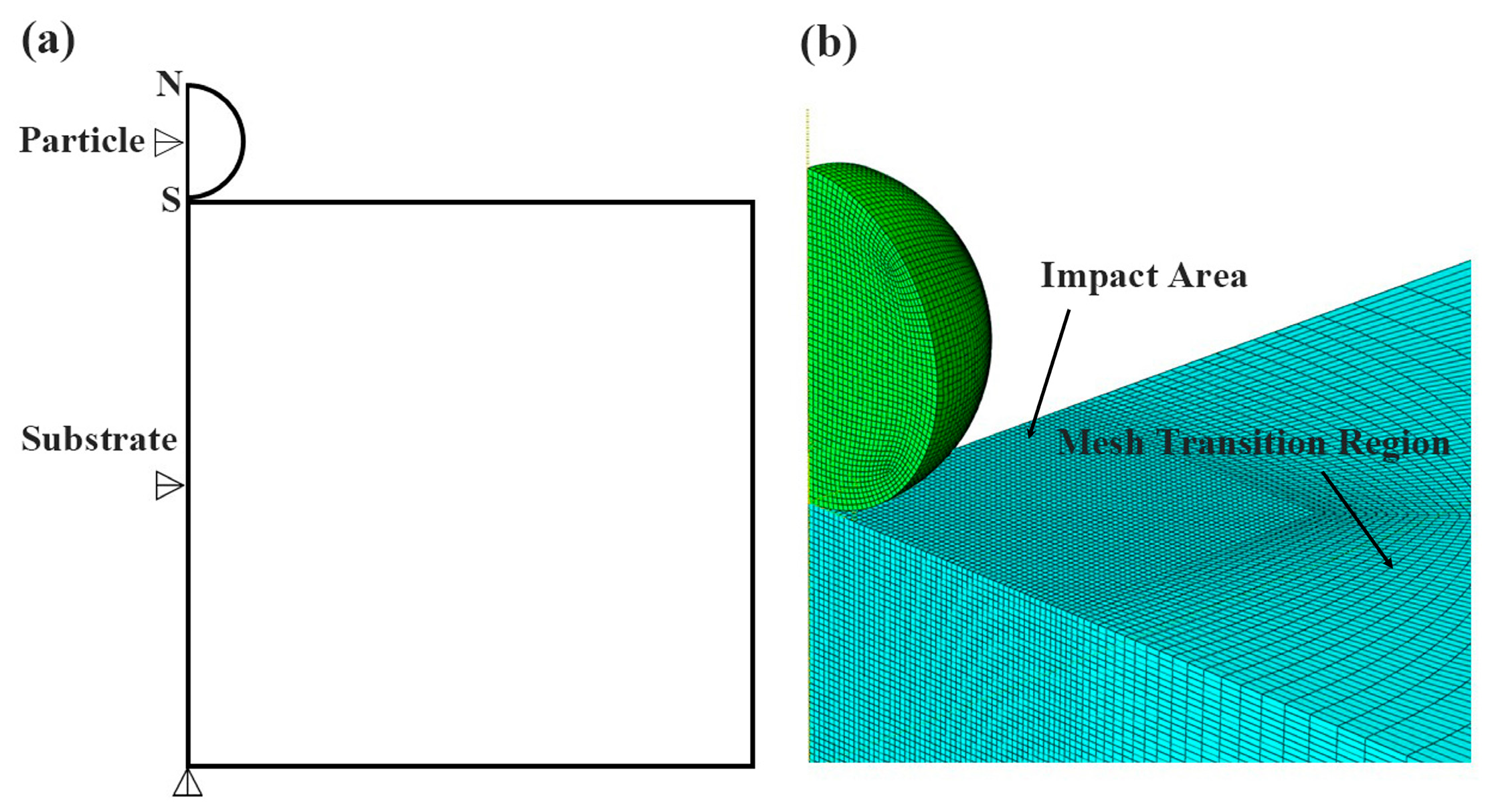
2. Finite Element Modeling Procedures

2.1. Modeling Method

In the current study, the impacting deposition behavior of a particle onto a substrate was studied using the FEM software ABAQUS/Explicit. ABAQUS is a commonly used commercial simulation software that can simulate a variety of complex physical processes. Display dynamics is an explicit integration-based method for simulating systems with highly nonlinear responses. It adopts a time-integral scheme that can handle large-scale system dynamic cold spraying problems and has efficient parallel computing capabilities. Explicit is often used in cold spraying simulation. Owing to the axisymmetric characteristics of the vertical impact process, an axisymmetric geometric model was chosen [44]. In order to obtain the actual deformation and changes in main parameters of particles and substrate, the three-dimensional (3D) model is established [45]. In this study, the shape of the particle was taken as a sphere, and the substrate was taken as a cylinder. The height and radius of the substrate were taken to be ten times the radius of the particle, given the substrate is infinite to the particle. The bottom and sides of the substrate are completely fixed in all directions, while the side surfaces are confined to the X and Y axes, respectively. The transition mesh has been used in the finite element simulation; to further improve the computational accuracy, the meshing size for the particle was 0.5 μm for a 25 μm particle. Also, to improve the calculation efficiency and ensure higher calculation accuracy, the mesh of the non-collision region adopts an asymptotic delineation method, and the farther away from the collision region, the more sparse the mesh is. Meanwhile, the size of the mesh has also been further tested. When the size of the mesh is reduced to a certain value, the difference between the node solution and the element solution is within 5%. Then the size of the mesh is considered reasonable and further refinement of the mesh is not necessary. The C3D8RT is an eight-node solid unit with bending and twisting capabilities that can simulate three-dimensional solids while solving complex structural problems, including structural dynamics, heat transfer and fluid dynamics. Using the C3D8RT unit can make the simulation have higher calculation accuracy and stability. The two-dimensional (2D) finite element model and 3D model meshing are shown in Figure 1.
Enhanced hourglass controls were used in the simulations for the thermo-mechanical analysis. The interaction of the particle and substrate was the surface-to-surface contact. During the deposition process, the initial temperatures of the particle and substrate were set to be 298 K.
During the finite element simulation, the following assumptions were made: (1) The contact interface between the particle and substrate is smooth, (2) The particle is impacting the substrate in a vertical direction, (3) The impacting process was considered as an adiabatic process, (4) The elastic response of the material is isotropic.
Owing to the large plastic deformation in the process of cold spray, when using a Lagrangian element, the contact edge between the particle and substrate will have excessive distortion of meshing at the local contact zones, and the mesh distortion will be severe, which easily leads to the non-convergence of the calculation results. In order to alleviate the degree of element distortion, the Arbitrary Lagrangian-Eulerian (ALE) method is selected for the meshing [30,32,44,45], which combines the characteristics of pure Lagrangian and Eulerian analysis; the particle and substrate can maintain a high-quality mesh in the process of finite element simulation, and the deformation is in line with the actual situation; meanwhile, compared with other meshing methods, it is possible to directly maintain the PEEQ, TEMP, stress-strain and other changes in the nodes. In order to improve the calculation efficiency and accuracy, only the region where the particle and substrate are in contact is selected for ALE meshing.

2.2. Material Model

Since the process of the particle impacting onto the substrate is characterized with high strain rate deformation and solid particle deposition, the Johnson-Cook (JC) plasticity model is suitable for thermal softening, strain hardening, and strain rate hardening effects. The JC plasticity model was used to simulate the process, in order to obtain information about the temperature and stress-strain of the deposited particles and substrate [46,47,48]. The JC model is defined as [49]
σ = [ A + B ε p n ] [ 1 + C l n ε ˙ p / ε ˙ p 0 ] × [ 1 ( T ) m ]
where A, B, C, and m are constants dependent on materials. n is the strain-hardening exponent, and all were obtained in experiments with low strain rates (<104 s−1). σ is the flow stress. εp is the equivalent plastic strain. ε ˙ p is the equivalent plastic strain rate. T is the applied temperature, ε ˙ p 0 is the reference plastic strain rate, and T* is defined as follows [50]:
T = 0 ( T < T m ) ( T T r ) / ( T m T r ) ( T r T T m ) 1 ( T > T m )
where Tm is the melting temperature and Tr is the reference temperature.
The mechanical properties of powder particles and substrates are shown in Table 1 [51], and the material parameters of the JC model are summarized in Table 2 [52,53].
The Mie-Gruneisen equation of state (EOS), which is defined for high velocity impact, is also required to simulate the elastic-plastic behavior of the particle and substrate, where the parameters include C0, S. Under the condition that 90% of the plastic work is converted into heat under adiabatic shear, the coupled thermal-structure analysis (Dynamic-Temp-Dis-Explict) is used to determine the generation and distribution of heat. Table 3 shows the Mie-Gruneisen EOS of materials [54].
Figure 2 shows the flow chart of finite element simulation guiding optimization of the experimental process of cold spray. Based on the current modeling and simulation results, the critical velocity (Vcr) of the as cold-sprayed coating has been obtained, so the direction of technique optimization can be found. Based on the optimized cold spray parameters, the as cold-sprayed NiCoCrAlY coating with excellent performance can been obtained via the subsequent experimental verification, such as the characterization of the composition and microstructure, the test of the adhesive strength of the as-sprayed coating.

3. Results and Discussion

3.1. The Deposition Behavior of Particles

The established model is a 3D model; in order to observe the deformation of particle and substrate more directly, the Y-Z axis plane is selected. Figure 3 shows the distribution of PEEQ with 25 μm particle size at different times at an impact velocity of 600 m/s. From (a)–(c), it can be seen that the particle is obviously deposited on the substrate. When the impact time is about 10 ns, the contact area between the particle and substrate increases rapidly, the particle gradually turns to flat, and strong plastic deformation occurs at the zone near the contact interface between the particle and substrate, and the maximum PEEQ changes abruptly.
The changes in kinetic and plastic dissipation energy for the whole system at the impact velocity of 600 m/s are shown in Figure 4, where the kinetic energy gradually decreases and the plastic dissipation energy gradually increases in the process of cold spray. Meanwhile, combined with Figure 3e,f, the plastic dissipation energy reaches the highest and tends to be flat at around 25 ns; the kinetic energy is also relatively low, indicating that serious plastic deformation occurs in the particle and substrate at around 25 ns.

3.2. Effect of Impact Velocity on the Deformation of the Particle

Figure 5 and Figure 6 show the finite element simulation results of PEEQ and TEMP with 25 μm particle impacting onto substrate at impact velocities of 400 m/s, 500 m/s, 600 m/s and 700 m/s within 30 ns, respectively. As can be seen in Figure 5 and Figure 6, the PEEQ and TEMP show a similar trend; the deformation of the particle and substrate being in an adiabatic process, there is also a significant temperature rise in the contact region between the particle and substrate when a large plastic deformation occurs. When the impact velocity increases, the PEEQ and TEMP increase accordingly. When the impact velocity reaches 500 m/s, the deformation of the particle is more obvious, and the contact zone between the particle and substrate is larger. The maximum PEEQ and TEMP occurs along the edge of the contact surface, indicating that the plastic deformation mainly occurred at the contact interface between the particle and substrate.
However, previous research [33,42] has shown that melting at the interface is not the necessary condition for particles deposition; particles can be considered to reach the critical velocity when adiabatic shear instability occurs. It has been reported that the temperature rise and heater transfer at the interface is not the key for deposition; strain can reasonably be viewed as the dominant factor [42]. Moreover, the deformation of the particle and substrate is mainly concentrated on the contact interface, so the PEEQ can be used as an important parameter in the cold spray process.
Figure 7 shows the variation of PEEQ and TEMP of 25 μm particles impacting onto the substrate for various impact velocities within 30 ns. In Figure 6a,b, the PEEQ and TEMP at the same velocity show a similar tendency. When the time is about 25 ns, the PEEQ and TEMP gradually tend to be stable, and the particle has reached the maximum value, which means that the particle has the largest plastic deformation. The less time particles deposition, the easier for the secondary impact of subsequent particles, and thus promote the improvement of deposition efficiency.
It is not difficult to see from Figure 7a that when the impact velocity is lower than 600 m/s, the changes in PEEQ are similar; the PEEQ for a period of time and tends to be smooth. With the increase in impact velocity, the PEEQ shows an increasing tendency, indicating a more intense degree of plastic deformation at a higher impact velocity. When the impact velocity reaches 600 m/s or above, the PEEQ changes abruptly within 10 ns to 15 ns, especially when the impact velocity is higher than 600 m/s. The PEEQ increases rapidly in a short time and fluctuates to a certain extent. It can be seen from Figure 6 that the effective plastic strain and fluctuation appear at the same impact moment, which means that adiabatic shear instability occurs in the particles. The main reason is that when the impact velocity of the particles reached the critical velocity, the increase in particle temperature led to the heat softening effect, which even exceeded the work hardening effect [55]. At the same time, the equivalent plastic strain and temperature show a downward trend, because the equivalent plastic strain energy will transform into internal energy during the deposition process of particles in the substrate [56]. Many studies had already shown that in the process of cold spraying, when the adiabatic shear instability occurs in the particle, the particle can be effectively deposited onto the substrate [30,31,33]. When the impact velocity is 600 m/s, the phenomenon of adiabatic shear instability has occurred in the particle, so it is reasonable to speculate that 600 m/s may be the critical velocity for the deposition of an NiCoCrAlY particle on the superalloy substrate.
Figure 8 shows the relationship between the maximum value of PEEQ and the impact velocity of the particle and substrate. Generally speaking, the maximum PEEQ of the particle and substrate increases with the increase in impact velocity; the maximum PEEQ of the particle is always larger than substrate, indicating that the deformation degree of the particle is more severe than the substrate, and the substrate is not easily deformed. When the impact velocity is lower than 550 m/s, the maximum PEEQ of the particle and substrate changes smoothly. When the impact velocity is higher than 550 m/s, both the maximum PEEQ of the particle and the substrate show a drastic increase, and the difference between the maximum PEEQ of the particle and the substrate is the largest when the impact velocity is 600 m/s. When the impact velocity is 650 m/s, the maximum PEEQ reaches the maximum, indicating that a very strong degree of deformation occurs at this stage, but the maximum PEEQ of the substrate has also exhibited an increasing trend. Accordingly, it can be further reasonably presumed that the critical velocity is about 600 m/s.

3.3. Effect of Particle Size on Deformation

Figure 9 shows the maximum PEEQ and impact velocity of the particle and substrate with different particle sizes. When the impact velocity is below 600 m/s, the maximum PEEQ increases with the increase in impact velocity and particle size. The maximum PEEQ of particles with diameters of 5 μm, 10 μm, 25 μm and 40 μm shows the same trend on the whole, the maximum PEEQ tends to be flat when the impact velocity is in the range of 600~650 m/s, then decreases when the impact velocity has increased to 700 m/s, which may be due to the fact that the particle has already reached the critical velocity, and adiabatic shear instability occurs. When the diameter is 50 μm, the maximum PEEQ increases in the range of 500~550 m/s and decreases at the velocity of 650 m/s. Studies [37,43,57] have further shown that when the particle size increases to a certain size, its critical velocity decreases. Larger particles are more likely to deposited when the velocity of particles with small size also decrease equally; due to their higher critical velocity than the corresponding critical velocity of large particles, small particles may not be able to deposit on the substrate. In addition, a larger particle will carry more kinetic energy, and the kinetic energy can transform more plastic strain energy, making it easier for larger particles to be deposited on the substrate. In addition, as it is well known, kinetic energy is positively correlated with the square of velocity and also with mass. However, when the critical velocity of large particles decreases, under the same spraying parameters, the velocity of particles coming out of the spray gun is basically fixed. More particles will come out of the spray gun exceeding the critical velocity. Due to the larger mass of large particles, they carry more kinetic energy, which is more conducive to their deposition on superalloy substrates. Therefore, it shows that when the particle size is within a certain limit, when the size of the particle increases, its critical velocity will decrease.
Figure 10 shows the changes in PEEQ in the period of 60 ns when particles with different particle sizes are impacting onto the substrate at 600 m/s within 60 ns. When the particles are smaller, the time which is needed to reach the maximum PEEQ is shorter, and gradually slows down. When the size of the particle is 5 μm, it needs 5 ns to reach the maximum PEEQ. When the size of the particle is 10 μm, it needs 30 ns to reach the maximum PEEQ. When the size of the particle is 50 μm, it needs 50 ns to reach the maximum PEEQ. Therefore, when the velocity reaches the critical velocity, the smaller the particle size, the shorter time required for completed deposition, the larger the particle, and the higher the PEEQ.
Figure 11 shows the PEEQ of the particles with different sizes at the impact velocity of 600 m/s. Combined with Figure 5c, it can be seen that the relationship between deformation degree and particle size is difficult to be clearly observed during deposition; possibly, the difference in particle size is not obvious. However, the larger the particle is, the more kinetic energy it carries, the higher its PEEQ, and is easily to plastic deformation, which suggests that the larger the particles are, the more easily they can be deposited on the substrate to a certain extent.
As for the cold-sprayed particles with a certain size, when their flight speed is relatively low, wear phenomenon will occur on the substrate. However, when the flight speed is high, particles will deposit on the substrate. The speed at which the wear transform to the deposition is called the critical speed, which is a very important parameter to ensure the cold spraying process being finished successfully (Figure 12a). Cold spraying of very small particles has two problems: the deceleration effect of bow-shaped shock waves and the critical velocity that increases as the particle size decreases. For a given cold spraying condition, there will be a certain particle size window, and sedimentation occurs when the velocity of particles in this window exceeds the critical velocity. The optimal particle size is to maximize the particle velocity increment above the critical velocity. Figure 12b shows a particle size range that can provide approximately the same increment of velocity (critical velocity of particle velocity), and this range is useful for controlling the process of reducing the impact of particle size on this metric. Above this range, the performance of the cold-sprayed coating decreases because the powder velocity decreases faster than the critical velocity. At particle sizes smaller than this range, the critical velocity increases faster than the particle velocity. The early modeling of critical velocity did not involve particle size effects that affect critical velocity. However, the experimental results indicate that the size of the critical velocity is influenced by the particle size. The critical velocity decreases with the increase in particle size until reaching the plateau region. Assuming that the mechanism of particle binding is based on the surface reaction and adiabatic shear mechanism generated by the destruction of the oxide film, and a decrease in particle size will lead to an increase in the surface area per unit volume of the oxide film and an increase in the thermal diffusion rate, it is difficult to achieve the temperature required for the adiabatic shear mechanism to be activated.

4. Experimental Materials and Methods

4.1. Materials and Spray

In the current experimental procedure, nickel-base superalloy GH4169 was selected as the substrate material, the original bar and plate were processed into the corresponding sample size, NiCoCrAlY (AMDRY 997, 5–38 μm, Oerlikon Metco, Nashville, TN, USA) was used as coating material, and the particle size was within a certain range; the main chemical components of powder particles and substrate are shown in Table 4. The NiCoCrAlY coating was prepared by the cold spray process. The process parameters were referred to the simulation results.
Before the coating deposition, the substrate is ultrasonically cleaned in order to remove surface impurities, and the substrate is sandblasted to obtain a certain cleanliness and roughness on the surface of the substrate, which is convenient for the subsequent deposition of particles. A sandblaster machine (AC-1, Foshan Ronggao Machinery Equipment Co., Ltd., Foshan, China) is selected, the pressure is 0.5 MPa, and the sandblasting distance is 100 mm; the brown corundum was accelerated to the substrate surface four times. The details of the cold spray process are shown in Figure 13. A commercial cold spraying system (Pcold spraying-100, Plasma Giken Co., Ltd., Saitama, Japan) with a nozzle (Pcold spraying-1000 L, Plasma Giken Co., Ltd.) assembly was used for coating deposition. Nitrogen was used as both the process gas and the powder-feeding gas during the sprays. A pressure of 4~4.5 MPa and a temperature of 700~750 °C of gas were used, at the same time the particles accelerated to 600 m/s and being deposited. Table 5 summarizes the cold spray parameters used for coating deposition.

4.2. Materials Characterization

Next, 18 KW high power rotating target X-ray diffraction (D8 ADVANCE, Bruker, Germany) was used to study the phase composition of the feedstock powder and as-sprayed coating. The samples were prepared according to standard metallographic procedures [58] (sectioning, mounting and polishing) for microstructure examination. The feedstock powder, surface morphology and cross-section of NiCoCrAlY coating were characterized by field emission scanning electron microscopy (CLARA, TESCAN, Czech Republic).
Adhesion tests were performed following the ASTM C633-13 standard [59] to evaluate the bonding strength of the NiCoCrAlY coating and GH4169 superalloy substrate. The adhesion tests were performed on three specimens. As shown in Figure 14a, the specimens were prepared to determine the bonding strength; one of the specimens for stretching is a coated cylinder and the other is a counter-partner of the same size. Figure 14b shows the actual bonding of specimens. The samples kept warm in a drying closet at 120 °C for 3 h, cooled for 48 h. Adhesion tests were carried out with the universal testing machine (SHSAS-CMT-5504, Material testing machine brand, China), the speed was set to 0.5 mm/min, as shown in Figure 14c, and applying the following equation: [60]
δ = F/A = F/πR2
where δ is strain, F is the pulling force at the moment and A is the testing area pulling surface of the specimen (506.7 mm2).

4.3. Results and Disducsion

Figure 15 shows the XRD spectrum of NiCoCrAlY powders and coating. The NiCoCrAlY powder shows sharp peak γ and β phases; in contrast, the γ phase diffraction peaks of cold spray coatings are broadened. This is attributed to the lattice strain and reduced grain size in cold spray coatings; the decrease of peak strength is due to serious material deformation [61]; at the same time, the β-NiAl phase disappeared. Some studies have shown that the disappearance of the β-NiAl phase is related to the plastic deformation that occurs during the deposition process, resulting in the dissolution of the β-NiAl phase in the γ phase [8,9]. The average grain size of phases in the feedstock and as cold-sprayed coating can be estimated based on XRD peak broadening by using the Debye Scherrer formula [62]:
D = k λ B 2 θ cos θ = k λ B obs 2 B std 2 cos θ
where k is a constant (being taken as 0.9), λ is the wavelength of the X-ray radiation, CuKα (λ = 1.5418 Å), D is the average grain size and θ is the Bragg angle. B(2θ) is the true broadening of the diffraction line at half-maximum intensity, also known as full-width at half-maximum (FWHM) after correction for the instrumental line broadening. Bobs is the measured FWHM of the peak and Bstd is the instrumental line broadening. XRD of a fully annealed silicon specimen was used to measure the instrumental broadening (i.e., Bstd) as it has no grain refinement, no stress (macro-stress or micro-stress) and no distortion. 2θ = 43.561° and 2θ = 43.622° peaks were selected to calculate the average grain size. The average grain size of the feedstock and as cold-sprayed coating were 75.1 nm and 29.8 nm, respectively. This shows that the grain size of the as cold-sprayed TBCs has significantly decreased after cold spraying due the strong plastic deformation of the deposited participles.
Figure 16 shows the image of a cross-section of NiCoCrAlY observed via SEM. Where Figure 14a is the surface morphology of NiCoCrAlY powders, the particles sizes are 5 ~ 38 μm, typical for gas atomized powders. According to the surface morphology of the NiCoCrAlY coating (Figure 14b), because particles are deposited on the substrate via plastic deformation during the cold spray process, only part of the contact interface of the particles is plastic-deformed; the rest remains spherical, and the surface is not smooth. At the same time, the deposited particles are subject to the secondary impact of other particles, and the coating is obtained through the multiple particles deposited. It can be seen from the cross-section view (Figure 14c) that the coating fabricated by cold spray has good densification, low porosity and oxygen content, the existing defects are very small, and the average thickness of NiCoCrAlY coating is 200 ± 20 μm.
Figure 17 shows the relationship of stress and strain in the process of the tensile test. During the process of the adhesion test, the deformation of the substrate appears, then cracks begin to occur and gradually propagate inside the coating with the continuous tensile loading of tensile stress. The coating separated from the substrate, resulting in failure. The average bonding strength of NiCoCrAlY coating is 35.99 ± 0.9 MPa. The results showed that the coating was well combined with the substrate and the particles deposited effectively.

5. Conclusions

In the current work, the deposition behavior of NiCoCrAlY powder particles impacting onto nickel-based superalloy GH4169 substrate has been systematically studied via the explicit dynamic method in finite element simulation, and the critical velocity was predicted. At the same time, based on the simulation results of the critical velocity, the cold spray parameters were optimized, and the NiCoCrAlY coating was successfully fabricated via the cold spray. The following conclusions can be drawn:
(1)
Based on the variation trends of PEEQ and TEMP obtained for various impact velocities, the critical velocity of NiCoCrAlY particles impacting onto nickel-based superalloy GH4169 substrate at 600 m/s can be reasonably predicted;
(2)
When the particle diameter is within a certain size range, its variation trend is roughly the same, but when the particle size is higher than a certain value, its critical velocity will be reduced. The larger the particle is, the easier it is to deposit on the substrate;
(3)
Based on the finite element simulation results, the suitable critical velocity for the cold-sprayed NiCoCrAlY coating has been obtained, and the cold-sprayed coating was prepared successfully; the as cold-sprayed coating has a dense microstructure and high bonding strength, which may be used as the bond-coat of the thermal barrier coatings.

Author Contributions

Conceptualization, Q.W. and J.S.; methodology, Q.W.; software, L.W.; validation, Q.W., W.Z. and J.L.; formal analysis, J.S.; investigation, Q.W.; resources, K.Z.; data curation, J.S.; writing—original draft preparation, Q.W.; writing—review and editing, Q.W. and L.W.; visualization, K.Z.; supervision, L.W.; project administration, K.Z.; funding acquisition, L.W. All authors have read and agreed to the published version of the manuscript.

Funding

This research was funded by a sub-project of the Key Basic Research Projects of Basic Strengthening Program (Grant No. 2020-JCJQ-ZD-172-05), National Defense Basic Research (JCKY2021603B007), the Training Program of the Major Research Plan of the National Natural Science Foundation of China (No. 91960107), the financial support from the National Natural Science Foundation of China (No. 52375222) and the National NSAF (Grant No. U1730139). This work was also supported by the Youth Innovation Promotion Association of the Chinese Academy of Sciences (Grant No. 2017295), Natural Science Foundation of Shanghai (No. 19ZR1479600). Great appreciation is also given to Prof. Renzhong Huang in Guangzhou Institute of Hubei Chaozhuo Aviation Technology Co., Ltd. for his assistance in the preparation of the cold-sprayed coatings.

Institutional Review Board Statement

Not applicable.

Informed Consent Statement

Not applicable.

Data Availability Statement

The data that support the findings of this study are available from the corresponding author, Zhang Ke, Liang Wang, upon reasonable request.

Conflicts of Interest

The authors declare no conflict of interest.

References

  1. Hassani-Gangaraj, M.; Veysset, D.; Champagne, V.K.; Nelson, K.A.; Schuh, C.A. Adiabatic shear instability is not necessary for adhesion in cold spray. Acta Mater. 2018, 158, 430–439. [Google Scholar] [CrossRef]
  2. Papyrin, A. Cold spray technology. Adv. Mater. Process. 2001, 159, 49–51. [Google Scholar]
  3. Raoelison, R.N.; Verdy, C.; Liao, H. Cold gas dynamic spray additive manufacturing today: Deposit possibilities, technological solutions and viable applications. Mater. Des. 2017, 133, 266–287. [Google Scholar] [CrossRef]
  4. Feng, P.; Rokni, M.R.; Nutt, S.R. Depositing aluminum onto PEKK composites by cold spray. J. Therm. Spray Technol. 2020, 30, 385–393. [Google Scholar] [CrossRef]
  5. Della Gatta, R.; Perna, A.S.; Viscusi, A.; Pasquino, G.; Astarita, A. Cold spray deposition of metallic coatings on polymers: A review. J. Mater. Sci. 2021, 57, 27–57. [Google Scholar] [CrossRef]
  6. Perna, A.S.; Viscusi, A.; Gatta, R.D.; Astarita, A. Integrating 3D printing of polymer matrix composites and metal additive layer manufacturing: Surface metallization of 3D printed composite panels through cold spray deposition of aluminium particles. Int. J. Mater. Form. 2022, 15, 15. [Google Scholar] [CrossRef]
  7. Li, Y.; Li, C.-J.; Yang, G.-J.; Xing, L.-K. Thermal fatigue behavior of thermal barrier coatings with the MCrAlY bond coats by cold spraying and low-pressure plasma spraying. Surf. Coat. Technol. 2010, 205, 2225–2233. [Google Scholar] [CrossRef]
  8. Guo, D.; Wang, Y.; Fernandez, R.; Zhao, L.; Jodoin, B. Cold spray for production of in-situ nanocrystalline MCrAlY coatings—Part I: Process analysis and microstructure characterization. Surf. Coat. Technol. 2021, 409, 126854. [Google Scholar] [CrossRef]
  9. Karaoglanli, A.C.; Ozgurluk, Y.; Doleker, K.M. Comparison of microstructure and oxidation behavior of CoNiCrAlY coatings produced by APS, SSAPS, D-gun, HVOF and CGDS techniques. Vacuum 2020, 180, 109609. [Google Scholar] [CrossRef]
  10. Assadi, H.; Kreye, H.; Gärtner, F.; Klassen, T. Cold spraying—A materials perspective. Acta Mater. 2016, 116, 382–407. [Google Scholar] [CrossRef]
  11. Wu, K.; Chee, S.W.; Sun, W.; Tan, A.W.-Y.; Tan, S.C.; Liu, E.; Zhou, W. Inconel 713C Coating by Cold Spray for Surface Enhancement of Inconel 718. Metals 2021, 11, 2048. [Google Scholar] [CrossRef]
  12. Zou, Y.; Qiu, Z.; Huang, C.; Zeng, D.; Lupoi, R.; Zhang, N.; Yin, S. Microstructure and tribological properties of Al2O3 reinforced FeCoNiCrMn high entropy alloy composite coatings by cold spray. Surf. Coat. Technol. 2022, 434, 128205. [Google Scholar] [CrossRef]
  13. Tang, J.; Tariq, N.u.H.; Zhao, Z.; Guo, M.; Liu, H.; Ren, Y.; Cui, X.; Shen, Y.; Wang, J.; Xiong, T. Microstructure and Mechanical Properties of Ti–Ta Composites Prepared Through Cold Spray Additive Manufacturing. Acta Metall. Sin. Engl. Lett. 2022, 35, 1465–1476. [Google Scholar] [CrossRef]
  14. Hu, D.; Mao, J.; Song, J.; Meng, F.; Shan, X.; Wang, R. Experimental investigation of grain size effect on fatigue crack growth rate in turbine disc superalloy GH4169 under different temperatures. Mater. Sci. Eng. A 2016, 669, 318–331. [Google Scholar] [CrossRef]
  15. Yang, X.; Li, W.; Ma, J.; Hu, S.; He, Y.; Li, L.; Xiao, B. Thermo-physical simulation of the compression testing for constitutive modeling of GH4169 superalloy during linear friction welding. J. Alloys Compd. 2016, 656, 395–407. [Google Scholar] [CrossRef]
  16. Li, H.; Niu, S.; Zhang, Q.; Fu, S.; Qu, N. Investigation of material removal in inner-jet electrochemical grinding of GH4169 alloy. Sci. Rep. 2017, 7, 608–616. [Google Scholar] [CrossRef]
  17. Clarke, D.R.; Oechsner, M.; Padture, N.P. Thermal-barrier coatings for more efficient gas-turbine engines. MRS Bull. 2012, 37, 891–898. [Google Scholar] [CrossRef]
  18. Vaßen, R.; Jarligo, M.O.; Steinke, T.; Mack, D.E.; Stöver, D. Overview on advanced thermal barrier coatings. Surf. Coat. Technol. 2010, 205, 938–942. [Google Scholar] [CrossRef]
  19. Weng, W.-X.; Wang, Y.-M.; Liao, Y.-M.; Li, C.-C.; Li, Q. Comparison of microstructural evolution and oxidation behaviour of NiCoCrAlY and CoNiCrAlY as bond coats used for thermal barrier coatings. Surf. Coat. Technol. 2018, 352, 285–294. [Google Scholar] [CrossRef]
  20. Padture, N.P.; Gell, M.; Jordan, E.H. Thermal barrier coatings for gas-turbine engine applications. Science 2002, 296, 280–284. [Google Scholar] [CrossRef]
  21. Doleker, K.M.; Karaoglanli, A.C. Comparison of Oxidation Behavior of Shot-Peened Plasma Spray Coatings with Cold Gas Dynamic Spray Coatings. Oxid. Met. 2016, 88, 121–132. [Google Scholar] [CrossRef]
  22. Guo, D.; Zhao, L.; Jodoin, B. Cold spray for production of in-situ nanocrystalline MCrAlY coatings—Part II: Isothermal oxidation performance. Surf. Coat. Technol. 2021, 409, 126828. [Google Scholar] [CrossRef]
  23. Karaoglanli, A.C.; Turk, A. Isothermal oxidation behavior and kinetics of thermal barrier coatings produced by cold gas dynamic spray technique. Surf. Coat. Technol. 2017, 318, 72–81. [Google Scholar] [CrossRef]
  24. Viscusi, A.; Astarita, A.; Gatta, R.D.; Rubino, F. A perspective review on the bonding mechanisms in cold gas dynamic spray. Surf. Eng. 2018, 35, 743–771. [Google Scholar] [CrossRef]
  25. Rahmati, S.; Jodoin, B. Physically Based Finite Element Modeling Method to Predict Metallic Bonding in Cold Spray. J. Therm. Spray Technol. 2020, 29, 611–629. [Google Scholar] [CrossRef]
  26. Samson, T.; MacDonald, D.; Fernández, R.; Jodoin, B. Effect of Pulsed Waterjet Surface Preparation on the Adhesion Strength of Cold Gas Dynamic Sprayed Aluminum Coatings. J. Therm. Spray Technol. 2015, 24, 984–993. [Google Scholar] [CrossRef]
  27. Archambault, G.; Jodoin, B.; Gaydos, S.; Yandouzi, M. Metallization of carbon fiber reinforced polymer composite by cold spray and lay-up molding processes. Surf. Coat. Technol. 2016, 300, 78–86. [Google Scholar] [CrossRef]
  28. Che, H.; Chu, X.; Vo, P.; Yue, S. Cold spray of mixed metal powders on carbon fibre reinforced polymers. Surf. Coat. Technol. 2017, 329, 232–243. [Google Scholar] [CrossRef]
  29. Li, W.-Y.; Gao, W. Some aspects on 3D numerical modeling of high velocity impact of particles in cold spraying by explicit finite element analysis. Appl. Surf. Sci. 2009, 255, 7878–7892. [Google Scholar] [CrossRef]
  30. Assadi, H.; Gärtner, F.; Stoltenhoff, T.; Kreye, H. Bonding mechanism in cold gas spraying. Acta Mater. 2003, 51, 4379–4394. [Google Scholar] [CrossRef]
  31. Schmidt, T.; Gärtner, F.; Assadi, H.; Kreye, H. Development of a generalized parameter window for cold spray deposition. Acta Mater. 2006, 54, 729–742. [Google Scholar] [CrossRef]
  32. Heydari Astaraee, A.; Colombo, C.; Bagherifard, S. Numerical Modeling of Bond Formation in Polymer Surface Metallization Using Cold Spray. J. Therm. Spray Technol. 2021, 30, 1765–1776. [Google Scholar] [CrossRef]
  33. Grujicic, M.; Zhao, C.L.; DeRosset, W.S.; Helfritch, D. Adiabatic shear instability based mechanism for particles/substrate bonding in the cold-gas dynamic-spray process. Mater. Des. 2004, 25, 681–688. [Google Scholar] [CrossRef]
  34. Meng, F.; Yue, S.; Song, J. Quantitative prediction of critical velocity and deposition efficiency in cold-spray: A finite-element study. Scr. Mater. 2015, 107, 83–87. [Google Scholar] [CrossRef]
  35. Meng, F.; Aydin, H.; Yue, S.; Song, J. The Effects of Contact Conditions on the Onset of Shear Instability in Cold-Spray. J. Therm. Spray Technol. 2015, 24, 711–719. [Google Scholar] [CrossRef]
  36. Shah, S.; Lee, J.; Rothstein, J.P. Numerical Simulations of the High-Velocity Impact of a Single Polymer Particle during Cold-Spray Deposition. J. Therm. Spray Technol. 2017, 26, 970–984. [Google Scholar] [CrossRef]
  37. Hassani-Gangaraj, M.; Veysset, D.; Nelson, K.A.; Schuh, C.A. In-Situ observations of single micro-particle impact bonding. Scr. Mater. 2018, 145, 9–13. [Google Scholar] [CrossRef]
  38. Loke, K.; Zhang, Z.-Q.; Narayanaswamy, S.; Koh, P.K.; Luzin, V.; Gnaupel-Herold, T.; Ang, A.S.M. Residual Stress Analysis of Cold Spray Coatings Sprayed at Angles Using Through-thickness Neutron Diffraction Measurement. J. Therm. Spray Technol. 2021, 30, 1810–1826. [Google Scholar] [CrossRef]
  39. Seng, D.H.L.; Zhang, Z.; Zhang, Z.-Q.; Meng, T.L.; Teo, S.L.; Tan, B.H.; Loi, Q.; Pan, J.; Ba, T. Impact of spray angle and particle velocity in cold sprayed IN718 coatings. Surf. Coat. Technol. 2023, 466, 129623. [Google Scholar] [CrossRef]
  40. Singh, N.K.; Uddin, K.Z.; Muthulingam, J.; Jha, R.; Koohbor, B. A Modeling Study of Bonding Mechanisms between Similar and Dissimilar Materials in Cold Spraying on Polymeric Substrates. J. Therm. Spray Technol. 2022, 31, 508–524. [Google Scholar] [CrossRef]
  41. Wang, F. Deposition characteristic of Al particles on Mg alloy micro-channel substrate by cold spray. Int. J. Adv. Manuf. Technol. 2016, 91, 791–802. [Google Scholar] [CrossRef]
  42. Ichikawa, Y.; Ogawa, K. Critical Deposition Condition of CoNiCrAlY Cold Spray Based on Particle Deformation Behavior. J. Therm. Spray Technol. 2016, 26, 340–349. [Google Scholar] [CrossRef]
  43. Dowding, I.; Hassani, M.; Sun, Y.; Veysset, D.; Nelson, K.A.; Schuh, C.A. Particle size effects in metallic microparticle impact-bonding. Acta Mater. 2020, 194, 40–48. [Google Scholar] [CrossRef]
  44. Li, W.-Y.; Zhang, C.; Li, C.-J.; Liao, H. Modeling Aspects of High Velocity Impact of Particles in Cold Spraying by Explicit Finite Element Analysis. J. Therm. Spray Technol. 2009, 18, 921–933. [Google Scholar] [CrossRef]
  45. Fardan, A.; Berndt, C.C.; Ahmed, R. Numerical modelling of particle impact and residual stresses in cold sprayed coatings: A review. Surf. Coat. Technol. 2021, 409, 126835. [Google Scholar] [CrossRef]
  46. Schreiber, J.M. Finite Element Implementation of the Preston-Tonks-Wallace Plasticity Model and Energy Based Bonding Parameter for the Cold Spray Process; The Pennsylvania State University: State College, PA, USA, 2016. [Google Scholar]
  47. Kong, X.; Li, B.; Jin, Z.; Geng, W. Broaching Performance of Superalloy GH4169 Based on FEM. J. Mater. Sci. Technol. 2011, 27, 1178–1184. [Google Scholar] [CrossRef]
  48. Lin, E.; Chen, Q.; Ozdemir, O.C.; Champagne, V.K.; Müftü, S. Effects of Interface Bonding on the Residual Stresses in Cold-Sprayed Al-6061: A Numerical Investigation. J. Therm. Spray Technol. 2019, 28, 472–483. [Google Scholar] [CrossRef]
  49. Johnson, G.R.; Cook, W.H. Fracture characteristics of three metals subjected to various strains, strain rates, temperatures and pressures. Eng. Fract. Mech. 1985, 21, 31–48. [Google Scholar] [CrossRef]
  50. Assadi, H.; Irkhin, I.; Gutzmann, H.; Gärtner, F.; Schulze, M.; Villa Vidaller, M.; Klassen, T. Determination of plastic constitutive properties of microparticles through single particle compression. Adv. Powder Technol. 2015, 26, 1544–1554. [Google Scholar] [CrossRef]
  51. Han, M.; Huang, J.; Chen, S. A parametric study of the Double-Ceramic-Layer Thermal Barrier Coating Part II: Optimization selection of mechanical parameters of the inside ceramic layer based on the effect on the stress distribution. Surf. Coat. Technol. 2014, 238, 93–117. [Google Scholar] [CrossRef]
  52. Ren, X.D.; Zhan, Q.B.; Yuan, S.Q.; Zhou, J.Z.; Wang, Y.; Ren, N.F.; Sun, G.F.; Zheng, L.M.; Dai, F.Z.; Yang, H.M.; et al. A finite element analysis of thermal relaxation of residual stress in laser shock processing Ni-based alloy GH4169. Mater. Des. 2014, 54, 708–711. [Google Scholar] [CrossRef]
  53. Wen, W.; Jackson, G.; Maskill, S.; McCartney, D.; Sun, W. Evaluating Mechanical Properties of CoNiCrAlY Coating from Miniature Specimen Testing at Elevated Temperature. Int. J. Mech. Mater. Eng. 2019, 13, 519–526. [Google Scholar]
  54. Lukyanov, A. Constitutive behaviour of anisotropic materials under shock loading. Int. J. Plast. 2008, 24, 140–167. [Google Scholar] [CrossRef]
  55. Van Steenkiste, T.H.; Smith, J.R.; Teets, R.E. Aluminum coatings via kinetic spray with relatively large powder particles. Surf. Coat. Technol. 2002, 154, 237–252. [Google Scholar] [CrossRef]
  56. Tsai, J.-T.; Akin, S.; Zhou, F.; Bahr, D.F.; Jun, M.B.-G. Establishing a Cold Spray Particle Deposition Window on Polymer Substrate. J. Therm. Spray Technol. 2021, 30, 1069–1080. [Google Scholar] [CrossRef]
  57. Aleksieieva, O.; Dereviankina, L.; Breuninger, P.; Bozoglu, M.; Tretiakov, P.; Toporov, A.; Antonyuk, S. Simulation of Particle Interaction with Surface Microdefects during Cold Gas-Dynamic Spraying. Coatings 2022, 12, 1297. [Google Scholar] [CrossRef]
  58. Sauer, J.P. The Use of Metallographic Standards in Calibration of the Polishing Process. In Proceedings of the ITSC 1997, Indianapolis, IN, USA, 15–18 September 1997; pp. 955–957. [Google Scholar]
  59. ASTM C633-13; Standard Test Method for Adhesion or Cohesion Strength of Thermal Spray Coatings. ASTM International: West Conshohocken, PA, USA, 2017.
  60. Portilla-Zea, K.; González, M.A.; Rodríguez, E.; Jiménez, O.; Bravo-Bárcenas, D.; Vásquez, G.I. Effect of SiC microfibers as a self-healing agent and their influence on oxidation and adhesion resistance of thermal barrier coatings exposed to cyclic thermal oxidation treatments. Surf. Coat. Technol. 2019, 372, 376–389. [Google Scholar] [CrossRef]
  61. Suryanarayana, C.; Norton, M.G.; Suryanarayana, C.; Norton, M.G. Determination of crystallite size and lattice strain. In X-ray Diffraction: A Practical Approach; Springer: Berlin/Heidelberg, Germany, 1998; pp. 207–221. [Google Scholar]
  62. Jiang, H.G.; Rühle, M.; Lavernia, E.J. On the applicability of the X-ray diffraction line profile analysis in extracting grain size and microstrain in nanocrystalline materials. J. Mater. Res. 2011, 14, 549–559. [Google Scholar] [CrossRef]
Figure 1. (a) 2D finite element model; (b) 3D meshing arrangement.
Coatings 13 01992 g001
Figure 2. Flow chart of finite element simulation guiding optimization of experimental process of cold spray.
Coatings 13 01992 g002
Figure 3. PEEQ of 25 μm particle and substrate within (a) 1 ns, (b) 3 ns, (c) 5 ns, (d) 10 ns, (e) 20 ns, (f) 30 ns at impact velocity of 600 m/s.
Coatings 13 01992 g003
Figure 4. History energy for 25 μm particle impacting substrate at 600 m/s as the function of the impacting time.
Coatings 13 01992 g004
Figure 5. PEEQ of 25 μm particle impacting substrate at impact velocity of (a) 400 m/s, (b) 500 m/s, (c) 600 m/s, (d) 700 m/s.
Coatings 13 01992 g005
Figure 6. Distribution of TEMP of 25 μm particle impacting onto the substrate at impact velocity of (a) 400 m/s, (b) 500 m/s, (c) 600 m/s, (d) 700 m/s.
Coatings 13 01992 g006
Figure 7. Changes of (a) PEEQ and (b) TEMP when 25 μm particle impacting onto substrate at various impact velocities within 30 ns.
Coatings 13 01992 g007
Figure 8. The plot of maximum PEEQ as the function of impact velocity for the particle and substrate.
Coatings 13 01992 g008
Figure 9. The maximum PEEQ as the function of impact velocity of particles with different sizes.
Coatings 13 01992 g009
Figure 10. Changes in PEEQ of particles with different size impacting onto substrate at 600 m/s within 60 ns.
Coatings 13 01992 g010
Figure 11. PEEQ of particle with different size (a) 5 μm, (b) 10 μm, (c) 40 μm, (d) 50 μm at the impact velocity of 600 m/s.
Coatings 13 01992 g011
Figure 12. The intrinsic relationship between critical velocity, particle velocity, and particle size. (a) The relationship between deposition efficiency and particle velocity. (b) The relationship between particle velocity and particle size.
Coatings 13 01992 g012
Figure 13. Schematic illustration of cold spray process.
Coatings 13 01992 g013
Figure 14. (a) specimen in the adhesion strength test; (b) schematic illustration of curing clamp; (c) image of adhesion strength test.
Coatings 13 01992 g014
Figure 15. XRD patterns of NiCoCrAlY powder and coating.
Coatings 13 01992 g015
Figure 16. SEM image of (a) powder particles topography, (b) surface topography of NiCoCrAlY coating, (c) cross-section of NiCoCrAlY coating.
Coatings 13 01992 g016
Figure 17. Relationship of stress and strain in the process of tensile test.
Coatings 13 01992 g017
Table 1. Mechanical properties of NiCoCrAlY and GH4169.
PropertiesParameter (Unit)NiCoCrAlYGH4169
GeneralDensity, ρ (Kg/m3)78008240
Specific heat, CP (J/Kg·K)628437
Thermal conductivity, (W/m·K)1514
Melting temperature, Tm (K)16531573
Inelastic heat fraction, β0.90.9
Elastic modulus, GPa152.4201
Poisson’s ratio0.3110.3
ElasticShear modulus, GPa58.177.3
Table 2. Johnson-Cook parameters of NiCoCrAlY and GH4169.
Parameter (Unit)NiCoCrAlYGH4169
A, MPa765.16860
B, MPa607.181100
n0.30.5
C0.0170.0082
m1.7151.05
Reference strain rate, ε ˙ 0 (s−1)11
Reference temperature, Tref (K)298298
Table 3. The Mie-Grüneisen Equation of State of NiCoCrAlY and GH4169.
Parameter (Unit)NiCoCrAlYGH4169
Sound velocity, C0 (m/s)33865800
Slope of UP versus US, S1.3391.489
Grüneisen coefficient, Γ01.972.02
Table 4. Chemical composition of NiCoCrAlY and GH4169 (wt.%).
NiCoCrAlTaYMoTi
AMDRY997 (5#)43.8722.8119.988.594.070.68
GH416950 ~ 5517 ~ 210.2 ~ 0.62.8 ~ 3.30.65 ~ 1.15
Table 5. Sand blast and cold spray conditions for deposited coating.
Sand Blast Cold Spray
PowdersBrown aluminium oxideFeedstock PowdersCoNiCrAlY
Size38#Spray Pressure4 ~ 4.5 MPa
Pressure0.5 MpaGas Temperature700~750 °C
Diatance100 mmWorking GasN2
Times4Powder feed rate50 g/min
Stand-off distance40 mm
Powder velocity600 [57] m/s
Disclaimer/Publisher’s Note: The statements, opinions and data contained in all publications are solely those of the individual author(s) and contributor(s) and not of MDPI and/or the editor(s). MDPI and/or the editor(s) disclaim responsibility for any injury to people or property resulting from any ideas, methods, instructions or products referred to in the content.

