Article

Preparation and Corrosion Properties of TiO2-SiO2-Al2O3 Composite Coating on Q235 Carbon Steel

School of Materials Science and Engineering, Shenyang Jianzhu University, Shenyang 110168, China
*
Author to whom correspondence should be addressed.
Coatings 2023, 13(12), 1994; https://doi.org/10.3390/coatings13121994
Submission received: 6 November 2023 / Revised: 22 November 2023 / Accepted: 22 November 2023 / Published: 23 November 2023

Abstract

:
The TiO2-SiO2-Al2O3 composite coatings were fabricated on the surfaces of Q235 carbon steel via the sol-gel method to improve its corrosion resistance. The effects of the sintering temperature and the layer number on the corrosion performances were explored. The coating morphology, microstructure and phase composition were analyzed by scanning electron microscopy (SEM) and X-ray diffractometer (XRD). Friction wear experiment, immersion experiment, and electrochemical impedance spectroscopy techniques were used to investigate the corrosion properties of the coatings as well. The results show that the sample with the TiO2-SiO2-Al2O3 coatings sintered at 850 °C are more uniform and denser and have better corrosion resistance and wear resistance than the other coatings. The Rp value of the 3 L coating sintered at 850 °C was about 114 kΩ·cm2, and the average friction coefficient was about 0.36.

1. Introduction

Carbon steel is one of the most commonly used metal materials and widely used in various fields, such as industry, energy and marine. However, carbon steel is extremely vulnerable to corrosion after use in marine environments. Corrosion causes not only unavoidable loss and safety problems in production and life, but also a certain amount of pollution to the environment [1,2,3]. At present, the common protection methods of carbon steel mainly include coating protection [4], cathodic protection [5], hot dip galvanizing [6] and so on. Among them, the coating technique is widely respected due to its simple process, less pollution, greater practicality, no restriction on the size and shape of the substrate, and better corrosion protection effect [7].
Coatings prepared on the surface of carbon steel can effectively prevent and isolate the migration of corrosive media to the metal surface, resulting in a significant reduction in the corrosion rate of the metal [8,9]. In recent years, composite coatings synthesized from two or more oxides have attracted much attention. They have been used to improve the mechanical properties and corrosion resistance of steel [10,11,12]. Studies have shown that coatings such as TiO2, SiO2 and TiO2-SiO2 are widely used to improve the corrosion resistance of metal substrates [13,14,15,16,17,18,19]. Among the many coatings, the Al2O3 coating is well known as a corrosion barrier and exhibits excellent wear and corrosion resistance. TiO2 and SiO2 are excellent coatings due to their chemical stability and good corrosion resistance [20,21,22,23,24,25]. The TiO2-SiO2 coatings deposited on 316 L stainless steel by the sol-gel method is effective as a corrosion protection agent in acidic media [26]. Forghani et al. [27] further improved the deposition of Al2O3-TiO2 by texturing the coating. Mora et al. [28] observed significant wrinkling of the coating underneath the metal substrate in the study of the effects of silica nanoparticles on the coating. The study found that the TiO2-SiO2-Al2O3 sol–gel powders have a considerable surface area, meaning that the powders are highly reactive [29]. In summary, composite coatings synthesized from a variety of oxides can effectively improve the performance of carbon steel. Among them, the sol-gel method is a simple and economical technique. It is easy to operate and can control the porosity, applying to a variety of substrates such as metals, glass, ceramics and plastics [30,31,32,33].
In this paper, many coatings, including the three-layer (TiO2-SiO2-Al2O3, 3 L) composite coating, were prepared on the surfaces of Q235 carbon steel by the sol-gel method. The corrosion properties of the coatings with different sintering temperatures and layer numbers were explored by immersion test, friction wear, immersion experiment, and electrochemical impedance spectroscopy, separately. In addition, the surface morphology and the structures of the coatings were further investigated to explain the anti-corrosion mechanism of the 3 L coating. The successful preparation of coatings and the improvement of corrosion performance provide a simpler and more effective reference for the anti-corrosion route of carbon steel.

2. Experimental

2.1. Materials and Solution

The Q235 carbon steel samples with the size of 25 mm × 25 mm × 2 mm were cleaned in an ultrasonic bath with ethanol and deionized water orderly. The surfaces of the samples were ground using sandpaper from 240# to 1000# polished successively. Then, the polished surfaces of the samples were completed by acid pickling, activating treatment and water washing processes. After that, the samples were placed in a 500 °C air furnace for 1 h to relieve residual stress. The uncoated Q235 carbon steel was used as a blank sample (BS) for comparison.

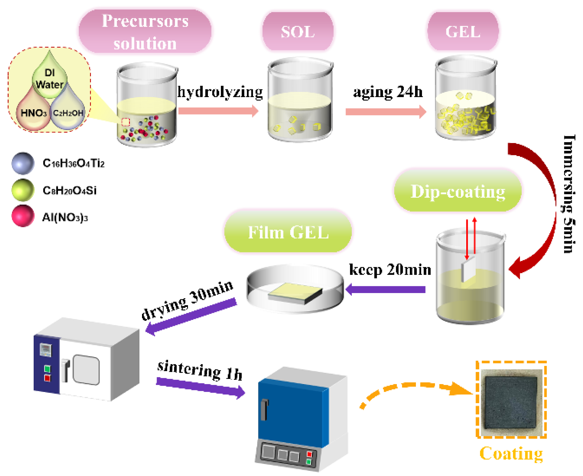
2.2. Experimental Materials and Preparation of Coating

Tetrabutyl titanate (Ti(OC4H9)4) and tetraethyl orthosilicate ((C2H5O)4Si) were used as titanium oxide and silicon oxide precursors, respectively. Aluminum nitrate served as the raw material for preparing alumina. Nitric acid, ethanol and distilled water were used as the catalyst, solvent and hydrolysis agent, respectively. Sol-gel was prepared by step hydrolysis method, and the specific process is as follows: 10 mL of butyl titanate was added into 40 mL of ethanol and then continuously stirred for 1 h to form solution A. A total of 6.7 mL of ethyl silicate was dissolved in 40 mL ethanol to obtain solution B. Simultaneously, 5 mL of deionized water, 2 mL of nitric acid and 10 mL of ethanol were stirred subsequently for 30 min to achieve a hydrolysis agent, which was dropped into solution A and solution B, respectively. Again, they were separately stirred for 1 h. An amount of 0.98 g of aluminum nitrate was mixed with 20 mL of ethanol for 1 h to obtain solution C. After that, solution B and solution C were orderly added to solution A under strong stirring for 3 h to obtain a yellow transparent sol. Finally, the gels were formed after the prepared sol was aged at room temperature for 24 h. The synthesis process is shown in Figure 1. These chemical reagents were purchased from Zhiyuan Chemical Reagent Co., Ltd. (Tianjin, China).
The prepared sol-gel coating was deposited on the steel substrate by dip-coating [34,35,36]. The carbon steel was vertically immersed in the aged sol at a constant rate. After immersion for 5 min, the steel samples were pulled out and were covered with a uniform coating (one layer, 1 L). After that, the coated samples were dried in an oven at 120 °C for 30 min. Finally, they were sintered at 550 °C, 650 °C, 750 °C, 850 °C at a heating rate of 4 °C/min for 1 h and named 550 °C–1 L, 650 °C–1 L, 750 °C–1 L, 850 °C–1 L, respectively.
For coating two layers (2 L), the coated samples were kept at room temperature for 20 min after the first immersion for 5 min. Likewise, the carbon steel with a uniform coating was vertically immersed in the sol at a constant rate. After immersion for 5 min, the steel samples were pulled out and were covered with the second uniform coating (two layers, 2 L). After that, the coated samples were dried in an oven at 120 °C for 30 min. Finally, they were sintered at 550 °C, 650 °C, 750 °C, 850 °C at a heating rate of 4 °C/min for 1 h and named 550 °C–2 L, 650 °C–2 L, 750 °C–2 L, 850 °C–2 L, respectively.
For coating three layers (3 L), the coated samples were kept at room temperature for 20 min after the second immersion for 5 min. Again, the carbon steel with two layers coating was vertically immersed in the sol at a constant rate. After immersion for 5 min, the steel samples were pulled out and were covered with the third uniform coating (three layers, 3 L). After that, the coated samples were dried in an oven at 120 °C for 30 min. Finally, they were sintered at 550 °C, 650 °C, 750 °C, 850 °C at a heating rate of 4 °C/min for 1 h and named 550 °C– 3 L, 650 °C–3 L, 750 °C–3 L, 850 °C–3 L, respectively.

2.3. Coating Characterization

The surface morphology of the coatings was analyzed using a scanning electron microscope (Hitachi S-4800, Tokyo, Japan). To prevent charging, the surfaces of the samples were sprayed with gold. The surface phase composition of the coatings was investigated by an X-ray diffractometer (Rapid II, Rigaku, Japan) set at a current of 35 mA and a voltage of 40 kV (diffraction angle ranging from 20° to 80° in a step of 0.02°). The results of XRD were analyzed using MDI jade 6.5® software.
The wear resistances of the coating and the BS were operated by a UTM-2 friction and wear tester. Under the condition of dry sliding friction at room temperature, the experimental frequency was 2 Hz, and the load was 15 N. The unidirectional stroke was 5 mm, and the friction time was 15 min. The friction partner was a YG8 carbide steel ball with a diameter of 5.0 mm, and the dry friction wear test was conducted without lubrication.

2.4. Electrochemical Experiments

The electrochemical experiments were performed using an electrochemical workstation (CS350H, CorrTest® Instrument Co., Ltd., Wuhan, China). A three-electrode electrochemical cell was explored in 3.5 (wt.) % NaCl solution throughout. The samples with 1 cm2 working area were utilized as the working electrode (WE). A platinum plate was used as counter electrode (CE). A saturated calomel electrode (SCE, +0.2412V vs. NHE) was used and allowed for measurement or control of the working electrode potential relative to SCE. The polarization curves were scanned at a rate of 1 mV/s and over a range of ±0.25 V relative to the open-circuit potential.
The electrochemical impedance spectroscopies were operated with sinusoidal perturbation amplitude of 10 mV and frequencies from 0.01 to 10,000 Hz. Two different equivalent circuits were used to illustrate the electrochemical values. The EIS results were analyzed using ZSimpWin3.22® software. All electrochemical tests were carried out using an automated laboratory unit (model PGSTAT302N,) and Nova 1.11 software. And the results were compared with the corrosion behavior of the coated and BS. To investigate the protective effect of the coatings, the optimally coated sample was immersed in 3.5% NaCl solution for 24 h, 48 h, 168 h and 336 h. Each electrochemical experiment was repeated three times to ensure reproducibility. All cell components used in the electrochemical measurement were made of glass or PTEF.

3. Results and Discussions

3.1. Surface Morphology

It is well known that surface morphology is an important parameter influencing the corrosion of metals. The SEM micrographs in Figure 2 exhibited the surface characteristics of TiO2-SiO2-Al2O3 3 L coatings sintered at 550 °C, 650 °C, 750 °C and 850 °C with different magnifications. It is clear from Figure 2a,c,e that there was no apparent crack on the surface of the composite coatings when the sintering temperatures were 550 °C, 650 °C and 750 °C. However, there were some cracks on the surface of the coating sintered at 850 °C (Figure 2g). The morphology with high magnification in Figure 2b shows that the coating sintered at 550 °C was inhomogeneous and was mainly constituted of fluffy filamentous microstructures. When the sintering temperature increased to 650 °C, the filamentous microstructures accumulated gradually and generated swellings (Figure 2d). When the sintering temperature was further increased to 750 °C, the coating layer was composed of intertwining vine-shaped microstructures. In addition, many holes appeared on the coating (Figure 2e). Compared with the coating samples sintered at 550 °C, 650 °C and 750 °C, the coating sintered at 850 °C presented compact columnar structures separated by grooves (Figure 2h). The phenomena of the coating morphologies varying at different sintering temperatures is possibly attributed to the rise of the coating components [15]. The surface morphology of the coating at different sintering temperatures in Figure 2a–h also reveal that the coating surface gradually became denser and the porosity decreased with the increase of sintering temperature.

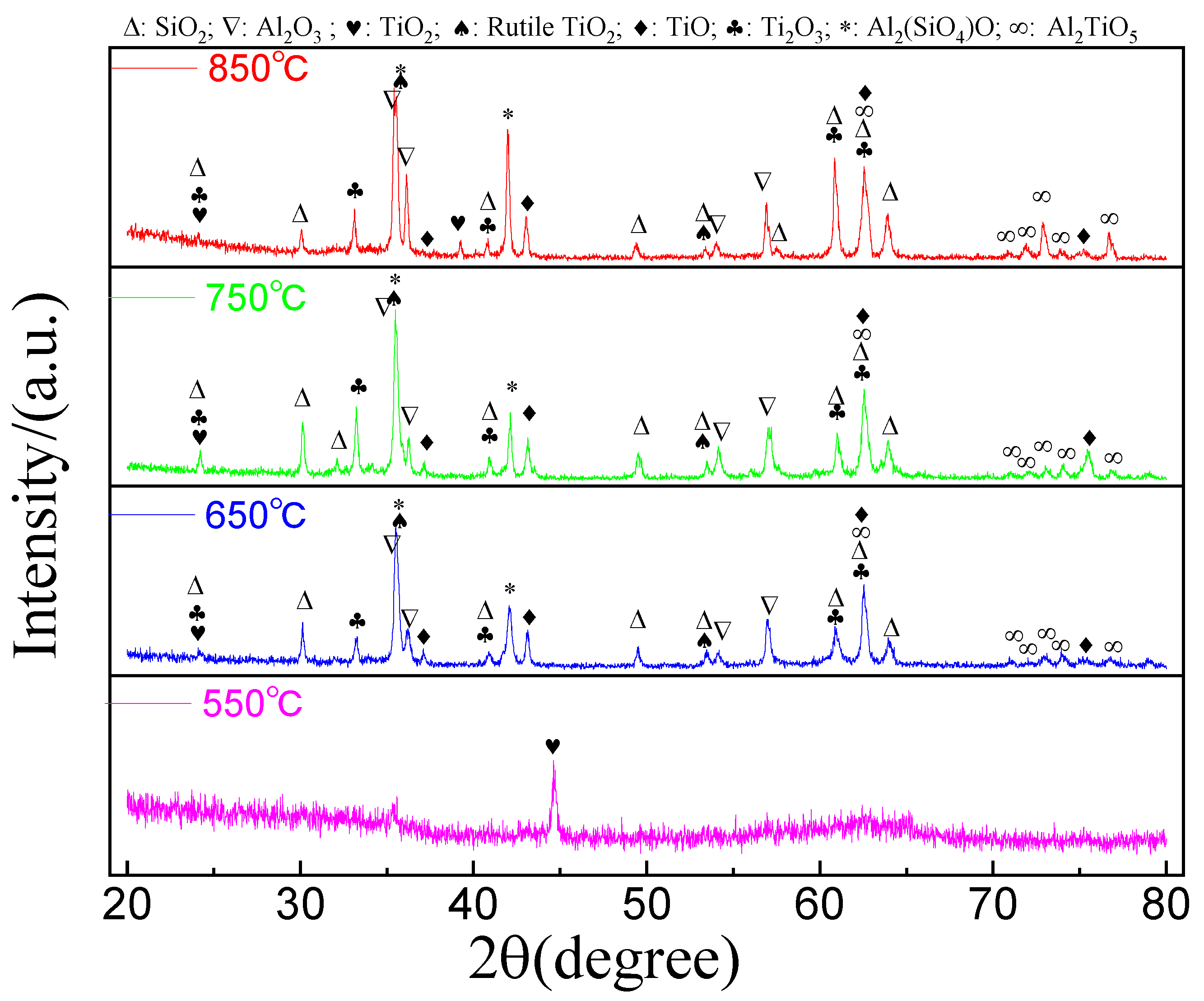
3.2. X-ray Diffraction Analysis

The crystalline phases of the coating on the carbon steel surfaces were examined by XRD. Figure 3 shows the XRD patterns of the coatings at sintering temperatures of 550 °C, 650 °C, 750 °C and 850 °C. It is clear from Figure 3 that the diffraction peaks of the coatings sintered at 850 °C, 750 °C and 650 °C are similar, and many kinds of oxides are detected. For instance, there are four kinds of titanium oxides, two kinds of silica and three kinds of alumina present in the coating sintered at 750 °C. The peaks located at (2θ) 24.23° and 39.29° were assigned to the (101) and (200) planes of TiO2 (JCPDS No. 70-2556), respectively. The peaks situated at 35.53° and 53.54° were due to (101) and (211) planes of rutile TiO2 (JCPDS No. 76-0325), separately. Additionally, the peaks positioned at 37.18° (111), 43.20° (200), 62.74° (220) and 75.24° (311) were attributed to TiO (JCPDS No. 77-2170), while the peaks stood at 23.83° (110), 33.055° (211), 40.23° (210), 61.31° (310) and 62.43° ( 1 2 ¯ 1 ) belonged to Ti2O3 (PDF 85-0868). The peaks sited at 25.58° (110), 35.16° (121), 52.57° (220) and 57.51° (123) were stemmed from Al2O3 (PDF 74-1081). The peaks of Al2O3 (PDF 70-3321) were detected as well and located at 36.17° (104) and 54.17° (024). The peaks of SiO2 (PDF 18-1170) were observed at 24.24° (311), 30.14° (−512), 32.20° ( 4 ¯ 08 ), 40.90° (711), 53.40° (427), 57.56° (822), 61.03° (824), 62.35° ( 4 ¯ 016 ) and 63.35° (137). The peaks of SiO2 (PDF 86-2333) were also present at 30.78° (110), 40.58° (101), 46.44° (111), 49.63° (210), 61.46° (211) and 78.70° (301). In addition, two composites were present as well. The peaks observed at 35.39° and 42.49° were assigned to the crystal planes of ( 3 ¯ 13 ) and ( 3 ¯ 14 ) of Al2(SiO4)O (PDF 89-0889), respectively. Similarly, the peaks situated at 62.79°, 72.86° and 76.70° were attributed to the composite of Al2TiO5 (PDF 73-1630). The peaks observed at 71.00°, 71.92° and 74.00° should be assigned to tail peaks of the peak at 72.86° of Al2TiO5 (PDF 73-1630). According to the peak positions in the three top curves of Figure 3, the main components are the same in the coatings sintered at 850 °C, 750 °C and 650 °C.
Nevertheless, the relative intensities of the peaks of the components are different, which indicates the relative amounts of the crystal phases in every coating are different. It is obvious from Figure 3 that the relative amounts of TiO and Ti2O3 in the coatings sintered at 750 °C and 650 °C are higher than that in the coating sintered at 850 °C. Furthermore, the amounts of Al2O3, Al2(SiO4)O and Al2TiO5 in the coating sintered at 850 °C are higher than that in the coatings sintered at 750 °C and 650 °C. However, the coating sintered at 550 °C presents amorphous phases together with the crystal phase of TiO2 (PDF 35-0088) located at 44.67° ( 5 ¯ 11 ).

3.3. Electrochemical Corrosion Behavior

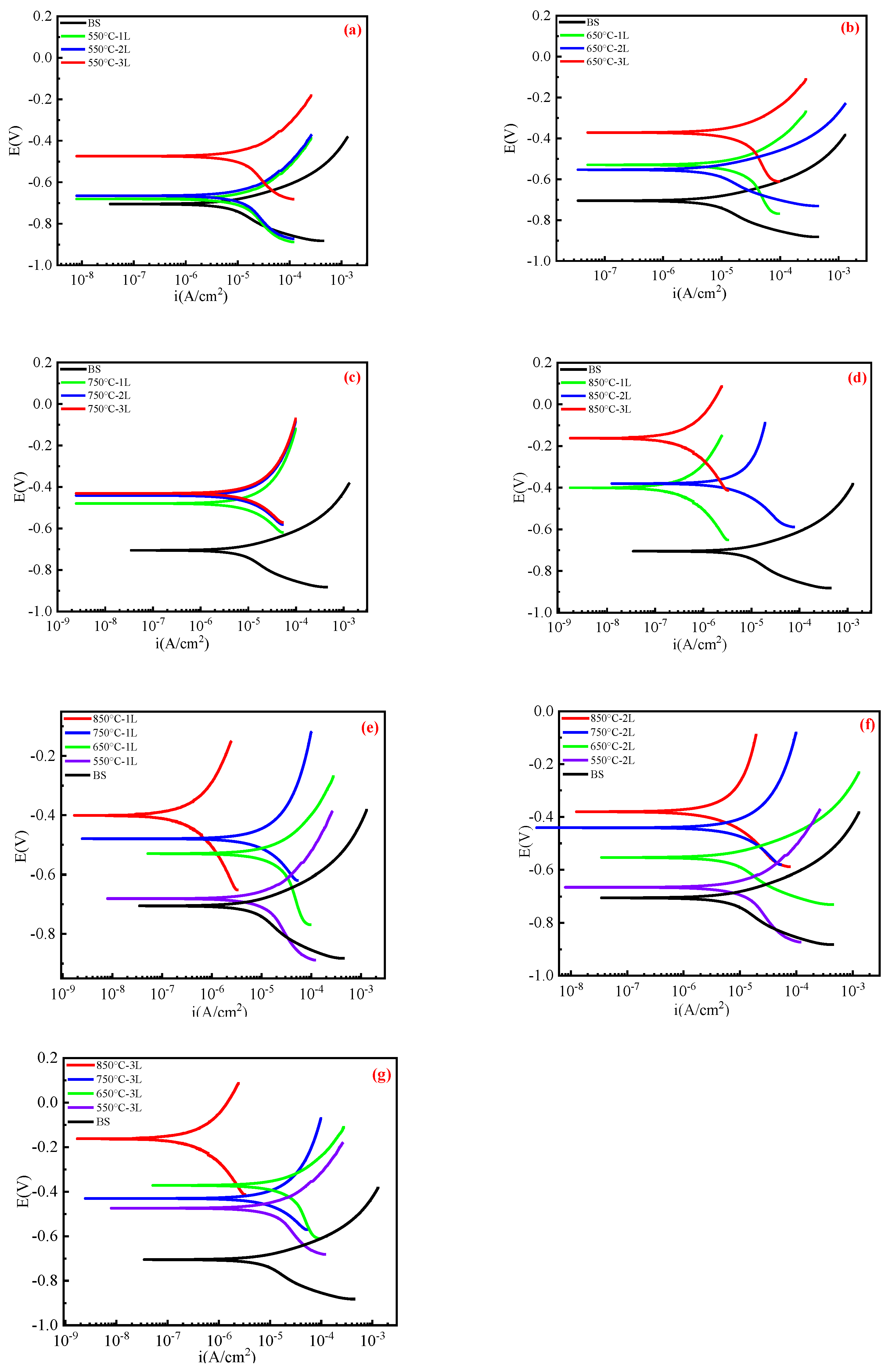
3.3.1. Linear Polarization

Figure 4 depicts the potentiodynamic polarization curves (A~G) of the BS and the composite coatings with different layers and sintered at various temperatures. The self-corrosion potentials (Ecorr) together with the corrosion current density (icorr) and the approximate polarization resistance (Rp) obtained by Tafel curve fitting are summarized in Table 1. It can be clearly observed from Figure 4 and Table 1 that the self-corrosion potentials of the coatings were more positive than that of the BS, while the corrosion current densities of the coatings were smaller than that of the BS. For instance, the Rp value of the 3 L coating sintered at 850 °C was about 114 kΩ·cm2, which was 110 times that of the BS at the same test conditions. It can be seen from Figure 4 and Table 1 that the corrosion performances were affected by the number and the sintering temperatures of coating layers. For the coatings, the highest Ecorr (−0.68 V) and Rp (1449 Ω·cm2) were attributed to the 1 L coating sintered at 550 °C. In addition, both Ecorr and icorr decreased while the polarization resistance increased with the number of coating layer and sintering temperature, respectively. The increase in the number of coating layers prevented the corrosion process from extending down to the surface of the substrate and thus improved the corrosion resistance [15].
Moreover, it can be seen from Table 1 that the 3 L coatings sintered at 550 °C, 650 °C, 750 °C and 850 °C have the lowest corrosion current density and the highest Rp. The corrosion current densities are 3.9 × 10⁻⁸ A/cm2, 3.5 × 10⁻⁸ A/cm2, 2.4 × 10⁻⁹ A/cm2 and 1.3 × 10⁻⁹ A/cm2, respectively. The corrosion current density is a significant parameter to characterize the corrosion resistance of the samples in salt solution and which is obtained from potentiodynamic polarization curves. In addition, Figure 4e–g displays that the corrosion potential of the coating increased from −0.68 V to −0.16 V with the increase in sintering temperature, indicating better protection from coatings sintered at 850 °C.
It is known that the positive shift in Ecorr suggests a decrease in the corrosion tendency, and Icorr is proportional to the corrosion rate [37]. Lower Icorr indicates higher corrosion resistance [38]. The positive shift of Ecorr and the decrease in Icorr indicated that the composite coating is efficient in protecting the Q235 carbon steel substrate from corrosion, and the protection property of the composite coating sintered at 850 °C was better than other temperatures, which was in agreement with the results of the polarization resistance.

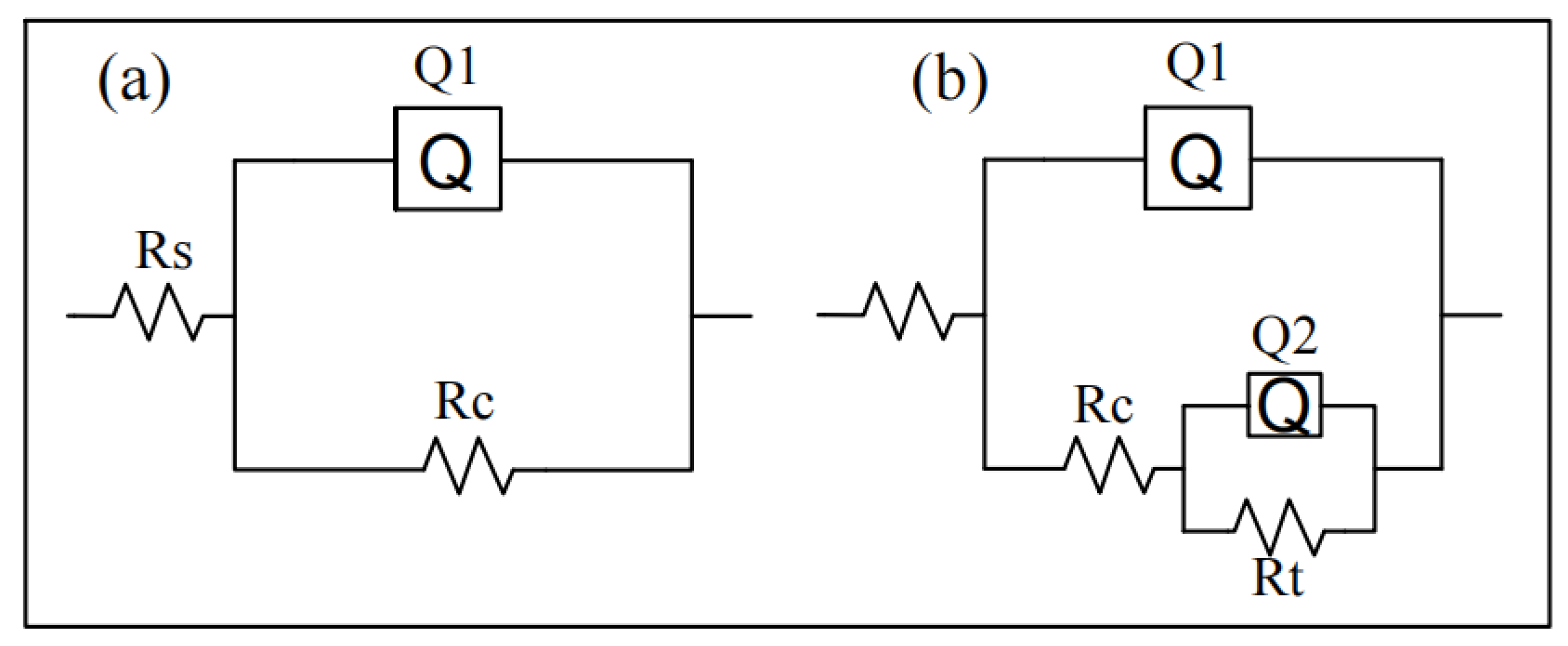
3.3.2. Electrochemical Impedance Spectroscopy

Electrochemical impedance spectroscopy (EIS) is an important electrochemical technique to provide key information about the polarization resistance of coatings. The resistance of the composite coatings was evaluated using EIS as well. Figure 5 shows that the Nyquist diagrams of EIS for 1 L, 2 L and 3 L coating samples sintered at different temperatures in 3.5% NaCl aqueous solution. The partial views of the impedance diagram were enlarged as the insets of Figure 5b–d. All impedance diagrams show the semicircle diameters of the capacitance arc of the composite coatings are much greater than that of the BS. And the larger diameter of the semicircle corresponds to a larger corrosion resistance [39]. As a result, it indicates that the coatings effectively improved the corrosion resistance of the Q235 carbon steel. Moreover, it can be observed that variation of the number of layers and sintering temperature changed the shape and the radius of the capacitance arc. The radii of the capacitance arc of the coatings enlarged with increasing sintering temperature. Moreover, the composite coatings sintered at 850 °C exhibit the greatest arc radius.
Figure 5a depicts the electrochemical impedance spectra of the coatings sintered at 550 °C. Obviously, two capacitive reactance arcs appeared in the EIS impedance spectra of the 1 L and 2 L coatings. The first (in the high-frequency range) characterizes the geometric capacitance of the porous oxide layer and the electrolyte resistance in the pores. The second arc is located in the low-frequency ranges, which can be attributed to the capacitance of the double electric layer at the interfacial boundary of the dense oxide layer with the substrate and to the charge transfer resistance [40].
The EIS impedance spectra consist of two time constants, corresponding to the high frequency characteristics and the low frequency characteristics of the protective coatings, which indicated that the corrosion behaviors were controlled by the charge transfer process [41]. It can be observed in Table 2 that the resistance (Rt) of the coating increased with the number of layers.
There is only one time constant on the EIS impedance spectra of the 3 L coating. The 3 L coating acted as a shielding layer to effectively isolate the direct contact between the corrosive medium and the substrate and thus protected the substrate from corrosion. It can also be observed from Figure 5b–d that the impedance spectrum radii of the capacitance arc of the 3 L coatings are higher than those of the other coatings sintered at the same temperature. The number of layers has a great influence on the corrosion resistance of the substrate.
Figure 5d shows that the Nyquist diagram of the coatings sintered at 850 °C has a larger circular diameter, which indicates that the coating effectively inhibits the invasion of corrosive ions to a certain extent and thus the coating protects the substrate from corrosion. Finally, it can be concluded that the Nyquist diagrams obtained by EIS test are largely consistent with the linear polarization results.
There are two appropriate equivalent circuits that were consistent with the results of the coating impedance test and that were used for the EIS data model of the coated samples and BS in Figure 6. Figure 6a is the equivalent circuits for the uncoated sample (BS); Rs, Rc and Q1 are the solution resistance, the polarization resistance and a constant phase element (Q1), respectively, whereas the equivalent circuit (Figure 6b) was utilized to measure the corrosion resistance of TiO2-SiO2-Al2O3 coated samples, which consists of the solution resistance (Rs), the series resistance (Rc), the coating charge–transfer resistance (Rt) and the capacitance (Q2). Usually, the phase angle element Q is used instead of the capacitor C to obtain a higher fitting result. Table 2 displays the results of all samples obtained from ZSimpWin3.3® software. The fluctuation of Rs is small in Table 2; it indicates that the test system is in a relatively stable state. The Rc and Rt values gradually increased with the growth of the number of layers., indicating that the corrosion rate of 3 L coatings is lower than other layers. Where n is between 0~1 that means the behavior of the constant element is resistance–capacitance behavior. The 3 L composite coating sintered at 850 °C displayed the largest Rt value among all the coatings (Table 2), and the Rt is about 3 × 10³ times that of the uncoated coating. It can be concluded that this is the best corrosion resistance verified by these electrochemical tests in this study.

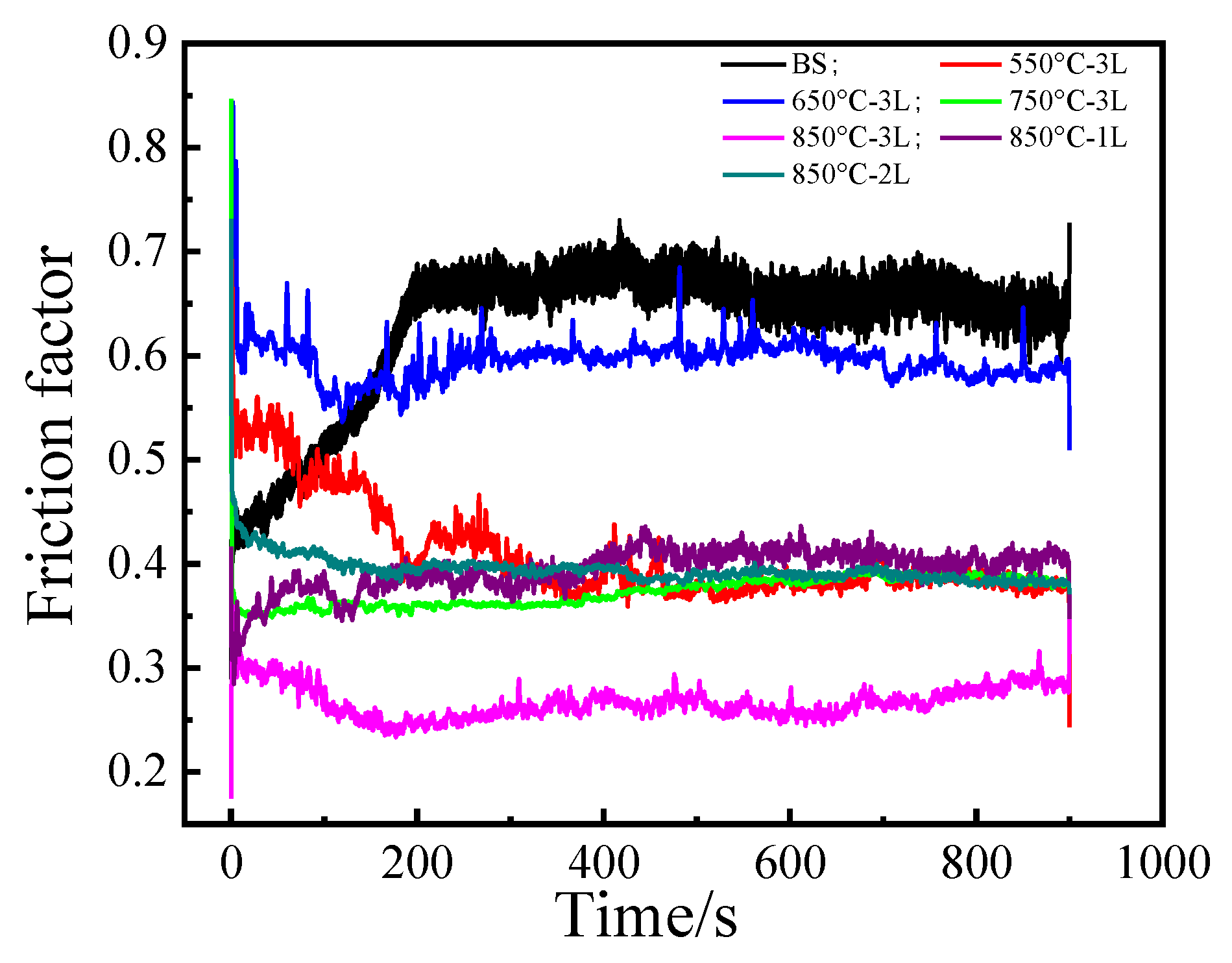
3.4. Friction Resistance Analysis

Figure 7 shows the change of friction coefficient of different coatings and BS with time. It can be seen from Figure 7 that the friction coefficient fluctuates during the first 200 s and then achieves dynamic balance afterwards. In addition, the friction coefficient of the coatings were less than that of the BS. The average friction coefficient of the BS is about 0.64, while the average friction coefficient of 550 °C–3 L, 650 °C–3 L, 750 °C–3 L and 850 °C–3 L coatings were approximately 0.41, 0.39, 0.37 and 0.36, respectively. It can also be seen from Figure 7 that the friction coefficient decreased with the increase in temperature. During the friction process, when the steel ball slid on the coating surface, the contact between the friction pairs was stable. The steel ball barely jumped, and the friction coefficient fluctuated stably. When sliding on the BS surface, the steel ball jumped obviously, and the friction coefficient fluctuated greatly.
Figure 7 depicts that the friction coefficient decreases with the increase in the number of layers. For the 850 °C–1 L, 850 °C–2 L and 850 °C–3 L coatings, the average friction coefficients were about 0.40, 0.39 and 0.36, separately. From the point of view of the coefficient of friction, the smaller the coefficient of friction, the better the surface friction. Therefore, the friction performances of the coatings are better than that of the BS, and the 850 °C–3 L coating has the best friction performance.

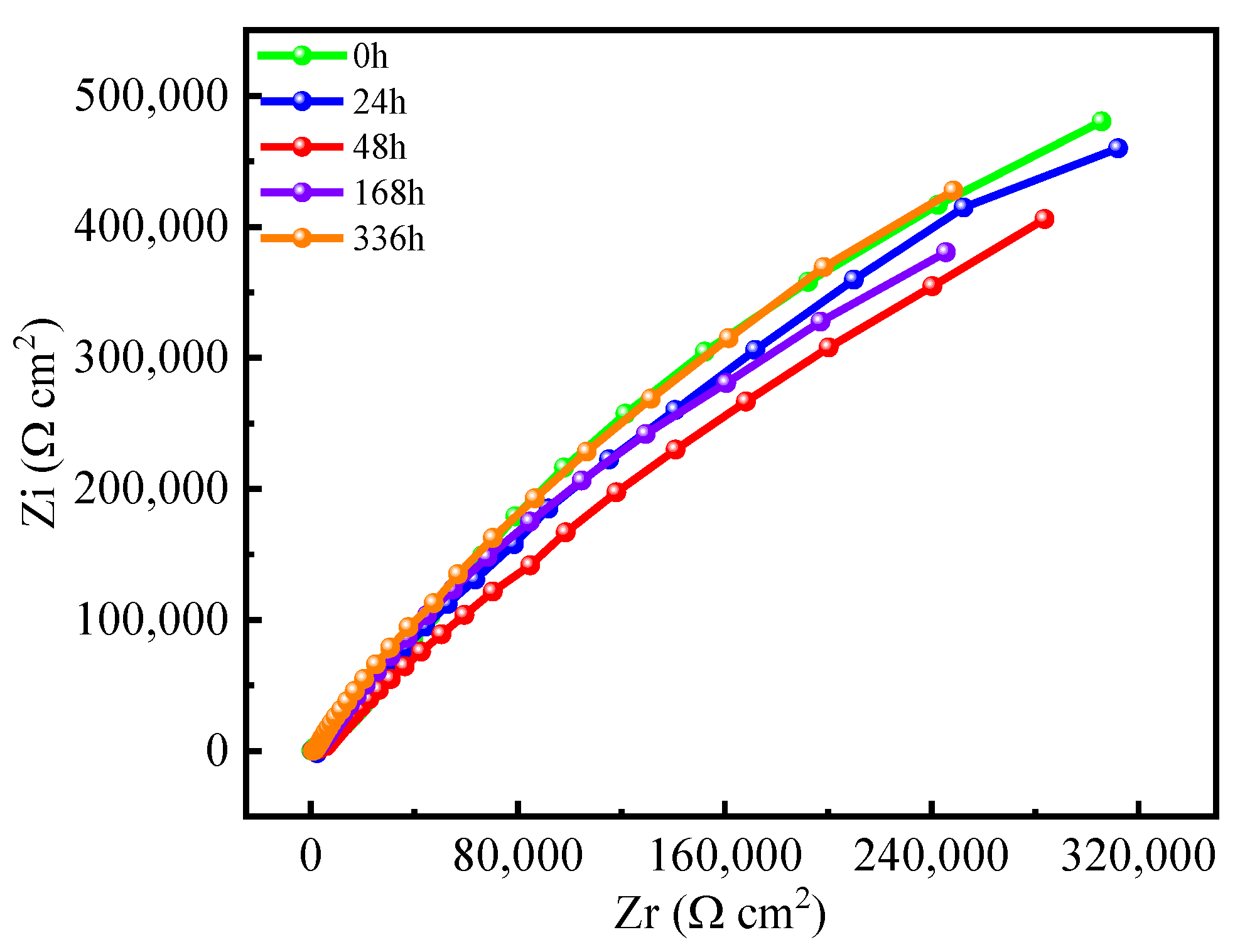
3.5. Immersion Experiment

In order to test the anti-corrosion effect of the composite coating on Q235 steel, the sample of 3 L coatings sintered at 850 °C were completely immersed in 3.5% NaCl solution for 0 h, 24 h, 48 h, 168 h and 336 h. Figure 8 shows the AC impedance spectra of the coatings after being immersed for different times. It can be seen from Figure 8 that the coating resistance decreases slightly with the prolongation of the immersion time. After being immersed for 336 h, the impedance radius of the coating became slightly larger, and the performance of the coating shielding corrosion medium was enhanced. The possible reason is a slight adsorption of H2O into the coatings therefore forming chemical bonding and chemical adsorption, blocking the micropores and permeation channels. Due to the permeation route of water, oxygen and other corrosive ions through the nanopolymer particles is extended, increasing the resistance of the medium to further diffuse into the coating. Usually, the size of the capacitive reactance arc radius reflects the size of the charge transfer resistance in the electrochemical corrosion process. The larger the capacitive arc radius with the larger the charge transfer resistance, the better the corrosion resistance of the material [42]. From Figure 8, the radius of the impedance spectrum before and after soaking has not changed obviously, indicating that the coating surface after immersion still has good corrosion resistance.

4. Conclusions

The study obtained the optimum parameters for the preparation of TiO2-SiO2-Al2O3 coatings on carbon steel by studying the effect of different sintering temperatures and number of layers on the composite coatings. And the surface morphology, corrosion resistance and friction properties of the TiO2-SiO2-Al2O3 composite coatings were investigated.
The SEM shows that the sintering temperature influenced the microstructural changes on the surface of the composite coating. With the increase of the sintering temperature, the coating surface gradually became denser, and the porosity decreased.
The XRD analysis of the coating fully verified that the coating sintered at 550 °C presents amorphous phases, while the main components are the same in the coatings sintered at 850 °C, 750 °C and 650 °C.
The corrosion resistance tests show that the increase in the number of coating layers also improves the corrosion resistance. The potentiodynamic electrochemical polarization tests indicated that all coatings had an apparent improvement in corrosion resistance as compared to the BS. The immersion experiments confirmed that the coating still had excellent corrosion resistance when immersed in 3.5% NaCl solution for 336 h. The coating successfully acted as a physical and electrochemical protective barrier to prevent the corrosion of the steel substrate. The 3 L TiO2-SiO2-Al2O3 composite coating at 850 °C greatly enhanced the polarization resistance to be 114 kΩ·cm2, much bigger than naked Q235 carbon steel.
Under dry friction conditions, the 3 L TiO2-SiO2-Al2O3 composite coating at 850 °C had the smallest friction coefficient. It was 0.36, and lower than the substrate under the same conditions. The coating can effectively act as friction resistance.

Author Contributions

Conceptualization, X.L. and Y.W.; methodology, X.L. and Y.W.; validation, X.L.; formal analysis, X.L. and Y.W.; investigation, X.L., Y.W. and X.Z.; resources, X.L. and Y.W.; data curation, X.L.; writing-original draft preparation, X.L.; writing-review and editing, X.L. and Y.W.; supervision, Y.W. All authors have read and agreed to the published version of the manuscript.

Funding

This research was funded by the Liaoning Revitalization Talent Program, grant number XLYC2002005.

Institutional Review Board Statement

Not applicable.

Informed Consent Statement

Not applicable.

Data Availability Statement

Data are contained within the article.

Conflicts of Interest

The authors declare that they have no conflict of interest.

References

  1. Vera, R.; Cruz, E.; Bagnara, M.; Araya, R.; Henríquez, R.; Díaz-Gómez, A.; Rojas, P. Evaluation of Anticorrosive Coatings on Carbon Steel in Marine Environments: Accelerated Corrosion Test and Field Exposure. Int. J. Electrochem. Sci. 2018, 13, 898–914. [Google Scholar] [CrossRef]
  2. Yang, H.; Zhang, Q.; Tu, S.; Wang, Y.; Li, Y.; Huang, Y. A study on time-variant corrosion model for immersed steel plate elements considering the effect of mechanical stress. Ocean Eng. 2016, 125, 134–146. [Google Scholar] [CrossRef]
  3. Li, X.; Zhang, D.; Liu, Z.; Li, Z.; Du, C.; Dong, C. Materials science: Share corrosion data. Nature 2015, 527, 441–442. [Google Scholar] [CrossRef] [PubMed]
  4. Fihri, A.; Bovero, E.; Al-Shahrani, A.; Al-Ghamdi, A.; Alabedi, G. Recent progress in superhydrophobic coatings used for steel protection: A review. Colloids Surf. A Physicochem. Eng. Asp. 2017, 520, 378–390. [Google Scholar] [CrossRef]
  5. Brenna, A.; Ormellese, M.; Lazzari, L. A proposal of AC corrosion mechanism of carbon steel in cathodic protection condition. In Proceedings of the NACE Corrosion Conference, Orlando, FL, USA, 17–21 March 2013; pp. 2013–2457. [Google Scholar]
  6. Yu, Z.; Hu, J.; Meng, H. A review of recent developments in coating systems for hot-dip galvanized steel. Front. Mater. 2020, 7, 74. [Google Scholar] [CrossRef]
  7. Akande, I.G.; Fayomi, O.S.I.; Oluwole, O.O. Performance of composite coating on carbon steel—A Necessity. Energy Procedia 2019, 157, 375–383. [Google Scholar] [CrossRef]
  8. Iroh, J.O.; Su, W. Corrosion performance of polypyrrole coating applied to low carbon steel by an electrochemical process. Electrochim. Acta 2000, 46, 15–24. [Google Scholar] [CrossRef]
  9. Subramanian, V.; Van Ooij, W.J. Effect of the amine functional group on corrosion rate of iron coated with films of organofunctional silanes. Corrosion 1998, 54, 204–215. [Google Scholar] [CrossRef]
  10. Tabish, M.; Malik, M.U.; Khan, M.A.; Yasin, G.; Asif, H.M.; Anjum, M.J.; Khan, W.Q.; Ibraheem, S.; Nguyen, T.A.; Slimani, Y.; et al. Construction of NiCo/graphene nanocomposite coating with bulges-like morphology for enhanced mechanical properties and corrosion resistance performance. J. Alloys Compd. 2021, 867, 159138. [Google Scholar] [CrossRef]
  11. Nazari, M.H.; Zhang, Y.; Mahmoodi, A.; Xu, G.; Yu, J.; Wu, J.; Shi, X. Nanocomposite organic coatings for corrosion protection of metals: A review of recent advances. Prog. Org. Coat. 2022, 162, 106573. [Google Scholar] [CrossRef]
  12. Wang, H.; Xu, J.; Du, X.; Du, Z.; Cheng, X.; Wang, H. A self-healing polyurethane-based composite coating with high strength and anti-corrosion properties for metal protection. Compos. Part B Eng. 2021, 225, 109273. [Google Scholar] [CrossRef]
  13. Steffi, A.P.; Balaji, R.; Prakash, N.; Rajesh, T.P.; Ethiraj, S.; Samuel, M.S.; Nadda, A.K.; Chandrasekar, N. Incorporation of SiO2 functionalized gC3N4 sheets with TiO2 nanoparticles to enhance the anticorrosion performance of metal specimens in aggressive Cl environment. Chemosphere 2022, 290, 133332. [Google Scholar] [CrossRef] [PubMed]
  14. Çomaklı, O.; Yazıcı, M.; Demir, M.; Yetim, A.F.; Çelik, A. Effect of bilayer numbers on structural, mechanical, tribological and corrosion properties of TiO2–SiO2 multilayer film-coated β-type Ti45Nb alloys. Ceram. Int. 2023, 4, 3007–3015. [Google Scholar] [CrossRef]
  15. Khosravi, H.S.; Veerapandiyan, V.K.; Vallant, R.; Reichmann, K. Effect of processing conditions on the structural properties and corrosion behavior of TiO2–SiO2 multilayer coatings derived via the sol-gel method. Ceram. Int. 2020, 46, 17741–17751. [Google Scholar] [CrossRef]
  16. Gutierrez, M.; Guerra, L.; Bermudez-Reyes, B.; Cabriales, R.; Reyes, L. Characterization of SiO2-TiO2 Coatings on 316L Stainless Steel Substrates. J. Adv. Mater. Process. 2018, 6, 3–13. [Google Scholar]
  17. Hayati, Z.; Hoomehr, B.; Khalesi, F.; Raeissi, K. Synthesis and electrophoretic deposition of TiO2-SiO2 composite nanoparticles on stainless steel substrate. J. Alloys Compd. 2023, 931, 167619. [Google Scholar] [CrossRef]
  18. Mazur, A.; Szczurek, A.; Chęcmanowski, J.G.; Szczygieł, B. Corrosion resistance and bioactivity of SiO2-Y2O3 coatings deposited on 316L steel. Surf. Coat. Technol. 2018, 350, 502–510. [Google Scholar] [CrossRef]
  19. Deyab, M.A.; Nada, A.A.; Hamdy, A. Comparative study on the corrosion and mechanical properties of nano-composite coatings incorporated with TiO2 nano-particles, TiO2 nano-tubes, and ZnO nano-flowers. Prog. Org. Coat. 2017, 105, 245–251. [Google Scholar] [CrossRef]
  20. Chęcmanowski, J.; Pelczarska, A.J.; Szczygieł, I.; Szczygieł, B. Influence of ceria and yttria on the protective properties of SiO2–Al2O3 coatings deposited by sol–gel method on FeCrAl alloy. J. Therm. Anal. Calorim. 2016, 126, 371–380. [Google Scholar] [CrossRef]
  21. Shi, Y.; Wang, N.; Liu, L.; Liu, Y. Surface sedimentation and adherence of Nano-SiO2 to improve thermal stability and flame resistance of melamine-formaldehyde foam via sol-gel method. Fire Mater. 2018, 42, 183–189. [Google Scholar] [CrossRef]
  22. Dias, V.M.; Chiappim, W.; Fraga, M.A.; Maciel, H.S.; Marciano, F.R.; Pessoa, R.S. Atomic layer deposition of TiO2 and Al2O3 thin films for the electrochemical study of corrosion protection in aluminum alloy cans used in beverage. Mater. Res. Express 2020, 7, 076408. [Google Scholar] [CrossRef]
  23. Mthisi, A.; Popoola, P.I. Influence of Al2O3 addition on the hardness and in vitro corrosion behavior of laser synthesized Ti-Al2O3 coatings on Ti-6Al-4V. Int. J. Adv. Manuf. Technol. 2019, 100, 917–927. [Google Scholar] [CrossRef]
  24. Ruhi, G.; Modi, O.P.; Sinha, A.S.K.; Singh, I.B. Effect of sintering temperatures on corrosion and wear properties of sol–gel alumina coatings on surface pre-treated mild steel. Corros. Sci. 2008, 50, 639–649. [Google Scholar] [CrossRef]
  25. Díaz, B.; Härkönen, E.; Maurice, V.; Światowska, J.; Seyeux, A.; Ritala, M.; Marcus, P. Failure mechanism of thin Al2O3 coatings grown by atomic layer deposition for corrosion protection of carbon steel. Electrochim. Acta 2011, 56, 9609–9618. [Google Scholar] [CrossRef]
  26. Atik, M.; De Lima Neto, P.; Aegerter, M.A.; Avaca, L.A. Sol-gel TiO2-SiO2 films as protective coatings against corrosion of 316L stainless steel in H2SO4 solutions. J. Appl. Electrochem. 1995, 25, 142–148. [Google Scholar] [CrossRef]
  27. Forghani, S.M.; Ghazali, M.J.; Muchtar, A.; Daud, A.R. Mechanical properties of plasma sprayed nanostructured TiO2 coatings on mild steel. Ceram. Int. 2014, 40, 7049–7056. [Google Scholar] [CrossRef]
  28. Mora, L.V.; Naik, S.; Paul, S.; Dawson, R.; Neville, A.; Barker, R. Influence of silica nanoparticles on corrosion resistance of sol-gel based coatings on mild steel. Surf. Coat. Technol. 2017, 324, 368–375. [Google Scholar] [CrossRef]
  29. Khalil, T.; El-Nour, F.A.; El-Gammal, B.; Boccaccini, A.R. Determination of surface area and porosity of sol–gel derived ceramic powders in the system TiO2–SiO2–Al2O3. Powder Technol. 2001, 114, 106–111. [Google Scholar] [CrossRef]
  30. Izumi, K.; Minami, N.; Uchida, Y. Sol-Gel-Derived Coatings on Steel Sheets. Key Eng. Mater. 1998, 150, 77–88. [Google Scholar] [CrossRef]
  31. Yu, J.; Ji, G.; Shi, Z.; Wang, X. Corrosion resistance of ZrO2 films under different humidity coal gas conditions at high temperature. J. Alloys Compd. 2018, 783, 371–378. [Google Scholar] [CrossRef]
  32. John, S.; Salam, A.; Baby, A.M.; Joseph, A. Corrosion inhibition of mild steel using chitosan/TiO2 nanocomposite coatings. Prog. Org. Coat. Int. Rev. J. 2019, 129, 254–259. [Google Scholar] [CrossRef]
  33. Sahnesarayi, M.K.; Sarpoolaky, H.; Rastegari, S. Effect of heat treatment temperature on the performance of nano-TiO2 coating in protecting 316L stainless steel against corrosion under UV illumination and dark conditions. Surf. Coat. Technol. 2014, 258, 861–870. [Google Scholar] [CrossRef]
  34. Krishna, V.; Padmapreetha, R.; Chandrasekhar, S.B.; Murugan, K.; Johnson, R. Oxidation resistant TiO2–SiO2 coatings on mild steel by Sol–Gel. Surf. Coat. Technol. 2019, 378, 125041. [Google Scholar] [CrossRef]
  35. Xia, B.; Liu, H.; Fan, Y.; Zhu, W.; Geng, C. Preparation of robust CuO/TiO2 superamphiphobic steel surface through chemical deposition and sol–gel methods. Adv. Eng. Mater. 2017, 19, 1600572. [Google Scholar] [CrossRef]
  36. Johari, N.D.; Rosli, Z.M.; Juoi, J.M.; Yazid, S.A. Comparison on the TiO2 crystalline phases deposited via dip and spin coating using green sol–gel route. J. Mater. Res. Technol. 2019, 8, 2350–2358. [Google Scholar] [CrossRef]
  37. Huong, H.T.; Nhu, T.T.Q.; Nang, H.X.; Tuan, P.A.; Huy, P.T. High transmittance and excellent hardness TiO2-SiO2-Al2O3 nanocomposite thin film for anti-scratch surface applications. Polym. Compos. 2022, 43, 7473–7482. [Google Scholar] [CrossRef]
  38. Li, Y.L.; Huang, Z.R.; Zhong, Q.D. Microstructure and Corrosive Behavior of Enamel Coating Modified on Mild Steel. Surf. Rev. Lett. 2018, 25, 1850081. [Google Scholar] [CrossRef]
  39. Dai, J.; Yang, J.; Zhuge, L.; Wu, X. Al2O3–TiO2 composite coatings with enhanced anticorrosion properties for 316L stainless steel. Mater. Corros. 2020, 71, 1512–1520. [Google Scholar] [CrossRef]
  40. Sobolev, A.; Bograchev, D.; Borodianskiy, K.; Zinigrad, M. Kinetics and mechanism of corrosion of oxide coating fabricated on aluminum alloy by the plasma electrolytic oxidation in molten salt. Corros. Sci. 2022, 208, 110604. [Google Scholar] [CrossRef]
  41. Mouele, E.S.M.; Myo, T.Z.M.; Kyaw, H.H.; Tijani, J.O.; Dinu, M.; Parau, A.C.; Pana, I.; El Ouardi, Y.; Al-Sabahi, J.; Al-Belushi, M.; et al. Degradation of sulfamethoxazole by double cylindrical dielectric barrier discharge system combined with Ti/CN-TiO2 supported nanocatalyst. J. Hazard. Mater. Adv. 2022, 5, 100051. [Google Scholar] [CrossRef]
  42. Hajiyan Pour, F.; Behpour, M.; Shabani-Nooshabadi, M.; Jafari, Y. Investigation of corrosion protection properties of TiO2-CdO nanocomposite coating prepared by sol-gel method on copper. J. Nanostructures 2020, 10, 52–63. [Google Scholar]
Figure 1. Preparation of the TiO2-SiO2-Al2O3 coatings.
Coatings 13 01994 g001
Figure 2. Surface and the corresponding high-magnification SEM micrographs of the TiO2-SiO2-Al2O3-3 L coatings sintered at (a,b) 550 °C, (c,d) 650 °C, (e,f) 750 °C and (g,h) 850 °C.
Coatings 13 01994 g002
Figure 3. XRD patterns of TiO2-SiO2-Al2O3 coatings sintered at 550 °C, 650 °C, 750 °C and 850 °C.
Coatings 13 01994 g003
Figure 4. Potentiodynamic polarization curves of Q235 carbon steel and the composite coatings with different layers sintered at various temperatures. (a) 550 °C, (b) 650 °C, (c) 750 °C, (d) 850 °C, (e) 1 L, (f) 2 L and (g) 3 L.
Coatings 13 01994 g004
Figure 5. Electrochemical impedance spectra of the 1 L, 2 L and 3 L TiO2-SiO2-Al2O3 coatings sintered at different temperatures. (a) 550 °C, (b) 650 °C, (c) 750 °C and (d) 850 °C.
Coatings 13 01994 g005
Figure 6. Equivalent electrical circuits for impedance data: BS and 1 L, 2 L and 3 L composite coatings sintered at different temperatures. (a) the equivalent circuits for uncoated sample BS, (b) the equivalent circuit for coated samples.
Coatings 13 01994 g006
Figure 7. Friction coefficient curves of 3 L composite coating sintered at different temperatures and BS.
Coatings 13 01994 g007
Figure 8. Electrochemical impedance spectra of 850 °C–3 L-TiO2-SiO2-Al2O3 coating soaked and unsoaked in 3.5%NaCl.
Coatings 13 01994 g008
Table 1. Polarization fitting data of the composite coatings in 3.5 (wt) % NaCl solution.
Samples Ecorr (V)Icorr (A/cm2)Rp (Ω·cm2)
BS −0.717.7 × 10−81028
550 °C1 L−0.686.3 × 10−81449
2 L−0.676.2 × 10−82004
3 L−0.473.9 × 10−82380
650 °C1 L−0.535.1 × 10−81362
2 L−0.555.2 × 10−83352
3 L−0.373.5 × 10−83358
750 °C1 L−0.482.5 × 10−91889
2 L−0.445.6 × 10−87043
3 L−0.432.4 × 10−98399
850 °C1 L−0.406.9 × 10−98277
2 L−0.341.7 × 10−921,213
3 L−0.161.3 × 10−9114,000
Table 2. The values of the equivalent circuit elements coinciding with the impedance spectra of composite coatings of 1 L, 2 L and 3 L at different temperatures compared to the BS.
SamplesRs (Ω·cm2)n1Rc (Ω·cm2)n2Rt (Ω·cm2)
RS42.25 0.6589.9
550-1 L14.920.444.510.7784.8
550-2 L39.860.872.680.8599.2
550-3 L56.880.7341.80.86023
650-1 L32.750.685.490.81257
650-2 L17.940.6686.40.75398
650-3 L31.170.538680.74684
750-1 L22.820.6106.90.8916.7
750-2 L10.420.5426.10.51178
750-3 L56.15140050.741,510
850-1 L24.590.755050.997,840
850-2 L25.63113,3600.6360,300
850-3 L28.280.715,5800.91,874,000
Disclaimer/Publisher’s Note: The statements, opinions and data contained in all publications are solely those of the individual author(s) and contributor(s) and not of MDPI and/or the editor(s). MDPI and/or the editor(s) disclaim responsibility for any injury to people or property resulting from any ideas, methods, instructions or products referred to in the content.

