Abstract
In the present study, (Cr,Al)N nanolayer coatings with different Al/Cr atomic ratios were deposited by magnetron sputtering on different substrate materials (H11 and D2 tool steel, alumina). To prepare the (Cr,Al)N coatings with different Al/Cr atomic ratios in the same batch, we used two targets composed of two triangle-like segments together with two standard Al and Cr targets. This approach enabled us to study the evolution of structural and mechanical properties in dependence on composition. The elemental composition of the coatings was determined by energy-dispersive X-ray analysis (EDS). The phase composition of the (Cr,Al)N coatings was determined utilizing X-ray diffraction (XRD), while scanning electron microscopy (SEM) was employed to assess their morphology and microstructure. The coating surface topography was analyzed by atomic force microscopy (AFM). In order to evaluate the effect of the Al/Cr atomic ratio on the oxidation behavior, the (Cr,Al)N coatings were oxidized in ambient atmospheres at temperatures between 700 and 850 °C and subsequently analyzed by means of cross-sectional SEM and transmission electron microscopy (TEM). The oxidation rate, determined by weight gain over time, was utilized to quantify the oxidation process. The oxidation tests showed that the Al-rich (Cr,Al)N nanolayer coatings exhibit a considerably better oxidation resistance than the Cr-rich ones. We found that the oxide scale formed on the Al-rich coating is composed of double layers: a Cr-oxide top layer and an inner (Cr,Al) mixed oxide layer. In contrast, the oxide scale of the Cr-rich coating mainly consists of the Cr2O3 layer. In particular, we focused on the oxidation process occurring at the locations of growth defects. We noticed that the first oxidation products on the coated substrate occurred at a temperature that was much lower than the temperature for the (Cr,Al)N coating oxidation initiation. These products (iron oxides) formed only at the sites of those growth defects that extended through the entire coating thickness.
1. Introduction
Advanced manufacturing technologies require tools that can withstand extreme mechanical and thermal loads. Examples include high-speed and dry machining, the machining of hard and difficult-to-cut workpiece materials as well as die casting, metal forming and plastic molding operations. The growing demands of these manufacturing processes can only be met with tools protected by high-performance PVD hard coatings. Such advanced hard coatings are also used in the protection of high-temperature stressed power plant components (e.g., gas turbine engine blades, turbochargers). In all these cases, the elevated temperature during the service of a tool or component caused detrimental oxidation and thermal decomposition of the protective coating. These processes deteriorate their mechanical and tribological properties. For this reason, the key properties of hard coatings for high-temperature applications must be their oxidation resistance and thermal stability.
Today, the most universal protective coatings, which largely meet these requirements, are based on (Cr,Al)N [1,2]. The first reports (Cr,Al)N hard coatings deposited by sputtering were published in 1990 [3,4], while the first commercial coating based on (Cr,Al)N (Balinit Alcrona) was developed in 2003 by the company Oerlikon Balzers AG (Balzers, Liechtenstein). This coating was prepared in the form of a monolayer by the cathodic arc deposition technique. Later the nanostructured coatings composed of (Cr,Al)N have been implemented in industrial production. In addition to the protection of cutting [5] and forming tools [6,7], the (Cr,Al)N-based coatings are also used in the automotive (e.g., valves, tappets and camshafts) [8] and aerospace industries (gas turbine engine blades) [9].
The enhanced strength of face-centered cubic (fcc) (Cr,Al)N originates from the solid solution hardening effect as a result of Cr atoms substitution in the fcc-CrN structure with Al ones. The incorporation of Al atoms into the CrN lattice forms a metastable substitutional solid solution and causes distortion of the lattice structure [10]. Consequently, the mechanical and tribological properties of the coating are significantly improved [10]. However, this only applies as long as the aluminum content is below 70 at. %. If the content of aluminum is higher, a hexagonal AlN phase (wurtzite) forms, which results in softening and reduction in the oxidation resistance of the coating, similar to TiAlN-based coatings.
The oxidation resistance of (Cr,Al)N coating increases with the share of Al up to the metastable limit [10,11]. The excellent oxidation resistance of (Cr,Al)N-based coatings during exposure to air at elevated temperatures is related to the formation of mixed Al2O3 and Cr2O3 scales. A dense oxide layer on the coating surface is formed by the diffusion of Cr and Al ions outwards and oxygen atoms inwards. The outer layer is Cr-rich, while the inner layer is Al-rich. The mixed Cr2O3 and Al2O3 oxide scale formed at an early stage of oxidation can provide an effective diffusion barrier that slows down the inward diffusion of oxygen anions and the outward diffusion of metal cations [12]. In order to effectively protect against further oxidation, the oxide scale must be stable, dense and well-adherent while its growth rate must be low. In such a case, the further oxidation of CrAlN coating is strongly hindered and most of the (Cr,Al)N matrix remains unaffected even after oxidation at 1000 °C.
The application of CrAlN at high temperatures is limited by two different thermal decomposition processes: (a) transformation of the metastable c-AlN into stable wurtzite AlN phase with low hardness; (b) transformation of c-CrN-phase into softer bcc Cr2N-phase due to the dissociation of the Cr-N bond associated with nitrogen loss [13,14,15]. The onset temperature for these processes is about 900 °C.
Therefore, any further improvement in the oxidation resistance and thermal stability of (Cr,Al)N coatings is still a great challenge for researchers. Several paths have been proposed to improve oxidation resistance. One approach is alloying with a fourth element (e.g., Y, Zr, Ti, Ta, Nb, Si) that has a stronger affinity to nitrogen in comparison to Cr. The (Cr,Al)N coatings doped with Si and Y show higher oxidation resistance [16,17,18,19,20,21,22], while the opposite effect was observed for Zr, Ti, Nb and Ta alloying elements [23,24,25,26]. The better oxidation resistance of (Cr,Al)N coatings alloyed with Y and Si is due to the segregation of both types of atoms to grain boundaries that block the diffusion of cations and anions. Additionally, the Si-doped CrAlN coatings also show improved corrosion resistance. Adding V suppresses the formation of the wurtzite AlN phase and the dissociation of Cr-N bonds and consequently improves the thermal stability of (Cr,Al)N coating [27]. At the same time, the high-temperature friction coefficient reduces due to the formation of V-based lubricious oxides. Ta is found to improve the thermal stability and mechanical properties of (Cr,Al)N coatings [26], while Zr-doped coatings show very good high-temperature tribological properties [23]. Hu et al. showed that the addition of 3–6 at. % of B improves the hardness and thermal stability of CrAlN coatings [28].
Another approach to optimize the high-temperature properties of (Cr,Al)N coating is the formation of a nanolayer structure composed of CrAlN layers and layers that possess exceptional thermal stability (TiSiN, TiAlN, TiAlSiN) [19]. In this case, the interfaces between individual layers act as a barrier for the diffusion of all atoms that participate in the oxidation process.
The oxidation resistance of (Cr,Al)N coatings also depends on their microstructure. Namely, all microstructural imperfections (voids at grain boundaries, columns and growth defects) are paths of faster diffusion of the metal atoms outward and oxygen atoms inward during oxidation. Therefore, the oxidation resistance of the coating is reduced by the presence of such imperfections. The microstructure of the coating is mainly dependent on the deposition method. For example, a coating density is much higher if it is deposited by high-power impulse magnetron sputtering (HIPIMS) [29] than by conventional DC sputtering. The coating microstructure can be influenced to some extent by the appropriate selection of deposition parameters (e.g., bias voltage).
It is generally known that all PVD coatings include growth defects, especially those prepared by cathodic arc deposition. Although there are many studies on the oxidation stability of (Cr,Al)N hard coating in the literature, none of these studies address the effect of growth defects on the oxidation process. In our previous paper [30], we discussed the influence of growth defects on the oxidation resistance of sputter-deposited TiAlN coatings in the form of a single layer. We found that oxidation processes are most intense at the points of those defects that extend to the substrate. These defects in the single-layer coating enable the direct diffusion of substrate atoms to the surface of the coating, where they oxidize. In this study, we consider the influence of the defects on the oxidation resistance of the nanolayer (Cr,Al)N coating composed of CrAlN/CrN/CrAlN/AlN nanolayers. This coating was used in our previously published study [31], where we investigated the soldering resistance of such nanolayer hard coatings in contact with molten Al-Si-Cu cast alloy at a temperature of 750 °C. We found that this particular coating reduced the soldering of cast alloy to a steel die applied for high-pressure die casting.
2. Materials and Methods
2.1. Coating Deposition
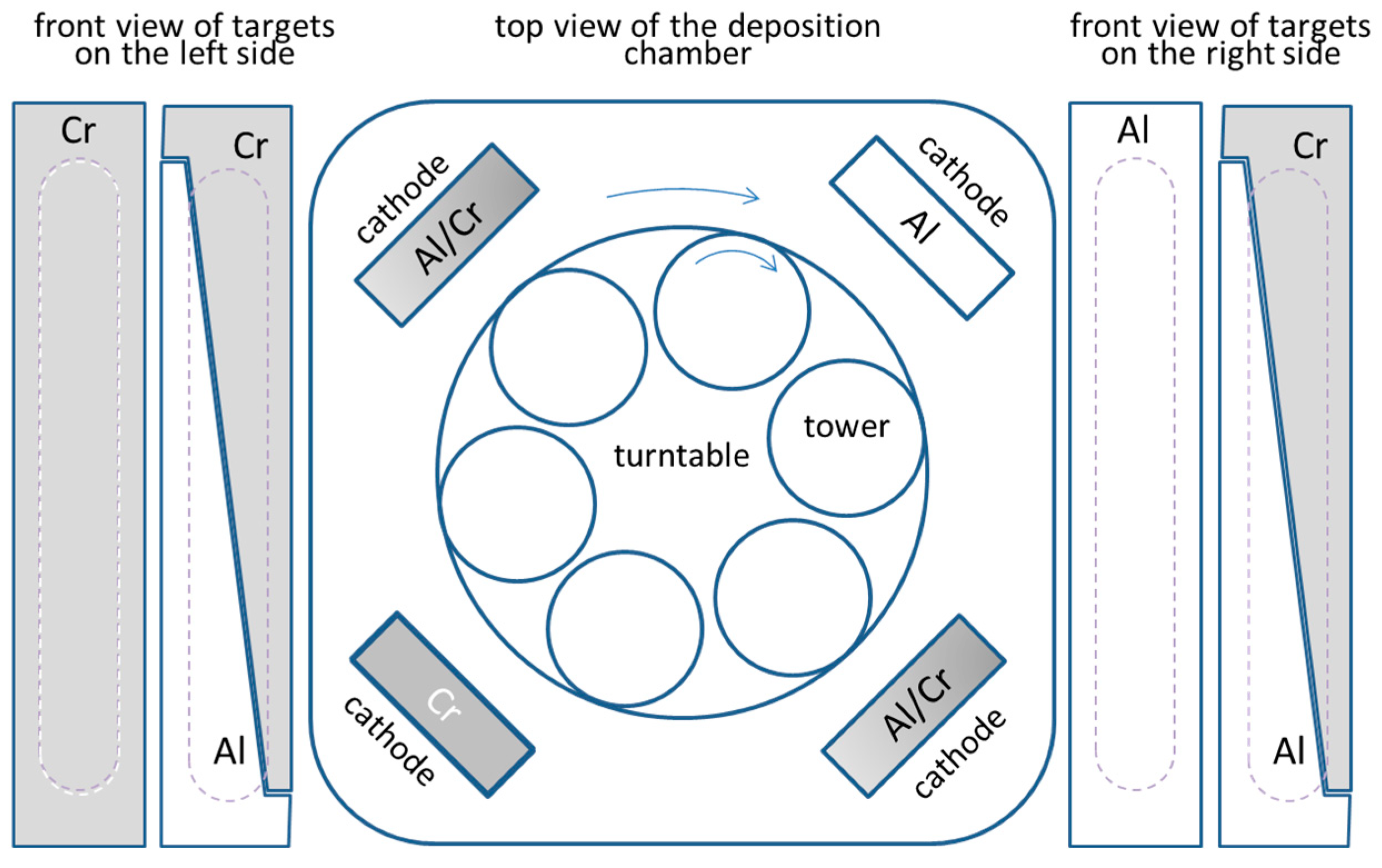
The nanolayered (Cr,Al)N coatings were deposited in an industrial coating unit CC800/9 ML (CemeCon, Wurselen, Germany). This system is equipped with four unbalanced magnetron sources placed at the corners of the vacuum chamber (Figure 1). The nanolayer CrAlN coatings were prepared by using one Al, one Cr and two triangle-like segmented targets. The size of the targets was 500 mm × 88 mm, while a purity of chromium and aluminum was 99.95% and 99.9%, respectively. The (Cr,Al)N coatings are composed of several hundred of CrAlN/CrN/CrAlN/AlN nanolayers, which resulted from the rotation of the substrates. The use of the target composed of triangle-like Cr and Al segments allowed us to deposit (Cr,Al)N coatings with different Al/Cr atomic ratios in the same batch. We achieved this by placing the substrates at different heights in the batch. All coatings were prepared by using a 2-fold substrate rotation. The target-to-substrate distance was about 8 cm when the substrates were facing the targets. The process parameters are given in Table 1.
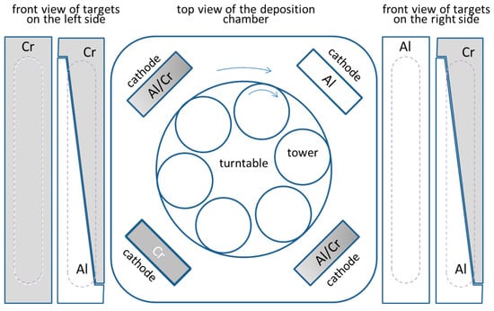
Figure 1.
Schematic illustration of the deposition system.

Table 1.
The process parameters during etching and deposition steps.
Disks made of cold work tool steel AISI D2 (hardness around 58 HRC, Ravne steel factory, Ravne, Slovenia) and hot working steel AISI H11 (48 HRC, Ravne steel factory, Ravne, Slovenia), both in a quenched and tempered state, and polished alumina (CoorsTek, Denver, CO, USA) were used as substrates in this study. Polished alumina substrates were pre-coated with a thin Cr layer in order to ensure electrical contact during the deposition processes. The roughness of the alumina was Ra = 25 nm, while the roughness of the tool steel substrates after grinding and polishing was about Ra = 10 nm. Before the deposition, the tool steel substrates were cleaned in an ultrasonic bath containing detergent solution (pH around 11), rinsed in deionized water and dried in hot air. After loading, the chamber was evacuated to a pressure below 4 mPa and heated up to the temperature of about 450 °C in order to remove the humidity and outgas the vacuum chamber and loading material. Before the coating deposition, the substrate surfaces were additionally cleaned and activated by ion etching using Ar and Kr ions generated from a MF discharge.
During the deposition run, the total operating pressure of mixed Ar/N2 was 0.5 Pa, with the flow rates of argon (99.999%) and nitrogen (99.99%) set to 200 and 50 mL/min, respectively. A DC bias of −120 V was applied to the substrate table, while the power on each target was 2.5 kW.
2.2. Coating Characterization
A field emission scanning electron microscope FE-JSEM 7001 (Jeol, Tokyo, Japan) was used to evaluate the surface topography, cross-sectional morphology and thickness of the deposited coatings. The micrographs of fracture cross-sections were taken with the secondary electron (SE) and backscattered electron (BSE) detectors. An energy-dispersive X-ray spectrometer (Oxford Instruments, Oxford, UK) built into the SEM microscope was used to determine the chemical composition of the coating. Cross-sections for the SEM investigation of selected growth defects were prepared using the FEI Helios NanoLab 600i focus ion beam system (Amsterdam, The Netherlands) integrated into a SEM microscope. Imaging was performed via electrons and ions. The EDS element mapping was also carried out to determine the qualitative distribution of the elements on the FIB cross-sections.
Cross-sectional scanning transmission electron microscopy (STEM) and energy-dispersive X-ray spectroscopy analysis were performed by using a JEOL JEM-2100 (Tokyo, Japan) operated at 200 kV. The cross-sectional specimens for TEM investigations were prepared via a focused ion beam technique using the standard lift-out technique. EDS mapping was also performed.
The surface topography of the coating at the nano level was studied using an atomic force microscope PARK NX20 (Suwon, Korea).
Phase identification and structural investigations of both as-deposited and oxidized coatings were conducted by X-ray diffraction with CuKα radiation (wavelength, λ = 0.15406 nm) using a Bruker AXS Endeavor D4 diffractometer (Bruker Inc., Billerica, MA, USA) in Bragg/Brentano mode at 40 mA and 40 kV.
Oxidation was studied by annealing the samples in a conventional tube furnace with ambient atmosphere at temperatures of 800 °C and 850 °C for periods ranging from 15 to 120 min. For oxidation rate measurements the polished alumina substrates were used. Periodically, the specimens were taken out of the furnace and weighed by a precise microbalance Mettler Toledo UM3 (Gießen, Germany).
A homemade ball cratering tester was used to determine the coating thickness. The hardness and Young modulus of the as-deposited coatings were measured by nanoindentation using a Fischerscope H100 instrument (Sindelfingen-Maichingen, Germany) with a Vickers indenter. Ten measurements were performed in the area outside of surface imperfections (growth defects, scratches) for each sample.
3. Results
3.1. Characterization of As-Deposited (Cr,Al)N Nanolayer Coatings
3.1.1. Coating Composition
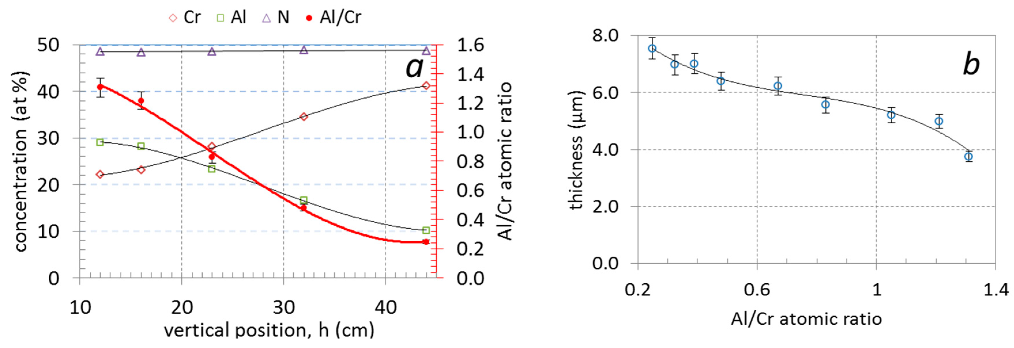
The use of triangle-like segmented targets enabled us to prepare (Cr,Al)N nanolayer coatings with different Al/Cr ratios in a single deposition batch. The chemical compositions of the coatings obtained from EDS measurements, as a function of the sample vertical position (h) in the chamber, are given in Table 2 and shown in Figure 2a. The Al content of the coatings was found to decrease from approximately 29 at. % for samples at the bottom to 10 at. % for those at the top; this correlated well with a simultaneous increase in the Cr content from approximately 22 to 40 at. %. In all investigated (Cr,Al)N nanolayer coatings, the composition was stoichiometric with around 50 at. % content of nitrogen, irrespective of the sample vertical position and target segment configuration. The Al/Cr atomic ratio of Al-rich (bottom samples) and Cr-rich coatings (top samples) are 1.3 and 0.26, respectively (Table 2, Figure 2a).
Table 2.
Properties of (Cr,Al)N nanolayer coatings deposited at different vertical positions (h): composition, thickness (t), individual layer thickness (tl), hardness (H), elastic modulus E, H/E ratio, H3/E2 ratio, surface roughness (Sa), full width at half maximum of the (111) diffraction peak (β), lattice parameter (a) and microstrain (ε).
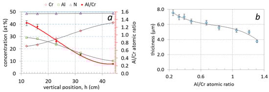
Figure 2.
Chemical composition (at. %) and Al/Cr atomic ratio of nanolayer (Cr,Al)N coatings as a function of vertical position (a) and the dependence of coating total thickness (b) on the Al/Cr atomic ratio.
3.1.2. Coating Thickness
The investigated (Cr,Al)N nanolayer coatings are composed of several hundred (Cr,Al)N/CrN/(Cr,Al)N/AlN nanolayers which were deposited in a repeated sequence. The coating thicknesses varied from 3.75 to 7.5 μm (see Table 2 and Figure 2b). The thicknesses of coatings with the highest share of Al was much lower than those with the highest share of chromium. The reason for this is that the sputtering yield for aluminum is about two times lower than for chromium [32,33]. The thicknesses of the individual Al-rich and Cr-rich layers, calculated from the total thickness, deposition time and rotation speed, are about 3 nm and 5.8 nm, respectively. The same single layers thicknesses were also estimated from cross-sectional TEM images (Figure 3). The darker layers in these images are Cr-rich (CrN, (Cr,Al)N), while the brighter ones are Al-rich (AlN, (Al,Cr)N).
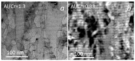
Figure 3.
Cross-sectional TEM images of (Cr,Al)N nanolayer coating with Al/Cr atomic ratios of 1.3 (a) and 0.33 (b). The Cr-rich layers are dark and the Al-rich ones are bright.
3.1.3. Coating Hardness
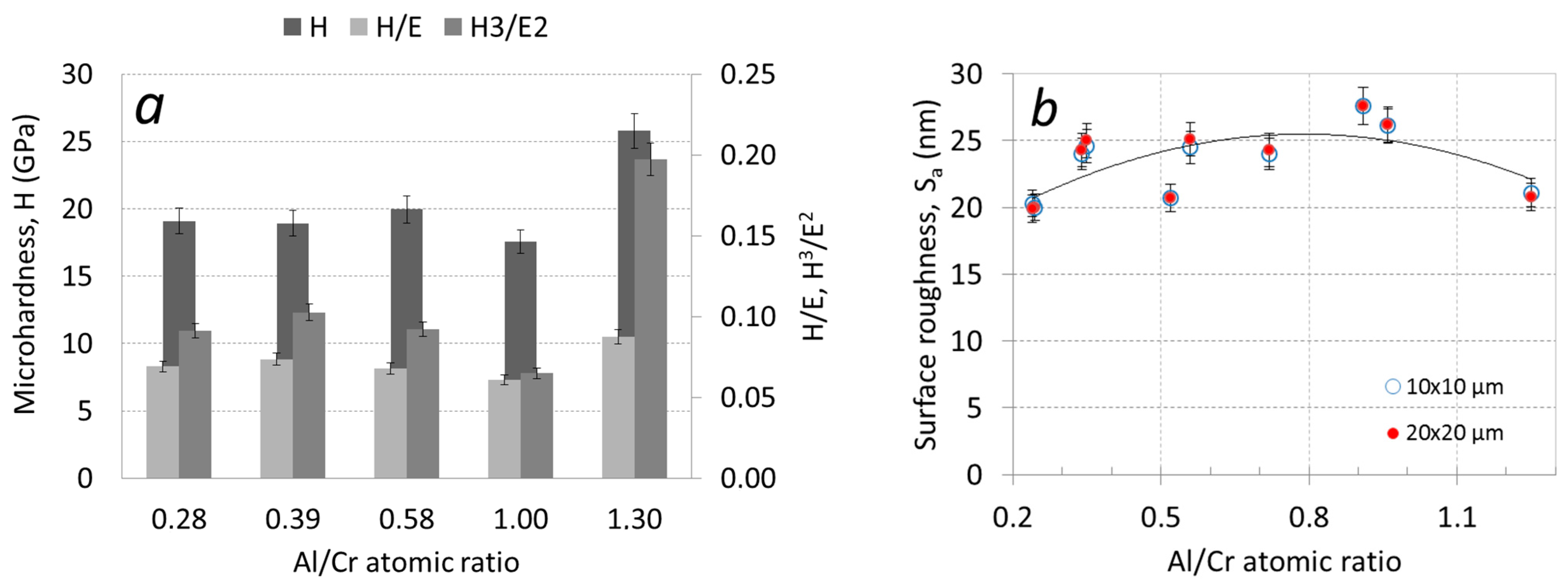
Nanoindentation tests were performed on the coatings deposited on H11 tool steel substrates. The microhardness of the Cr-rich nanolayer (Cr,Al)N coatings was around 1800 HV, while it increased to 2600 HV for Al-rich coating (Table 2, Figure 4a). As listed in Table 2, the Al-rich (Cr,Al)N coating exhibits the highest elasticity index (H/E) and plasticity index (H3/E2). The elastic modulus was calculated by using the Poisson’s ratio of 0.25 [34]. Higher values of these parameters normally indicate better tribological performance of such coatings. Namely, in order to increase the fracture toughness and yield strength of the coating, both high hardness and low elastic modulus are required.
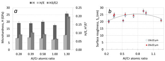
Figure 4.
Microhardness H/E and H3/E2 ratios (a) and AFM surface roughness Sa (b) as a function of the Al/Cr atomic ratio.
3.1.4. Surface Topography and Microstructure of (Cr,Al)N Nanolayer Coatings
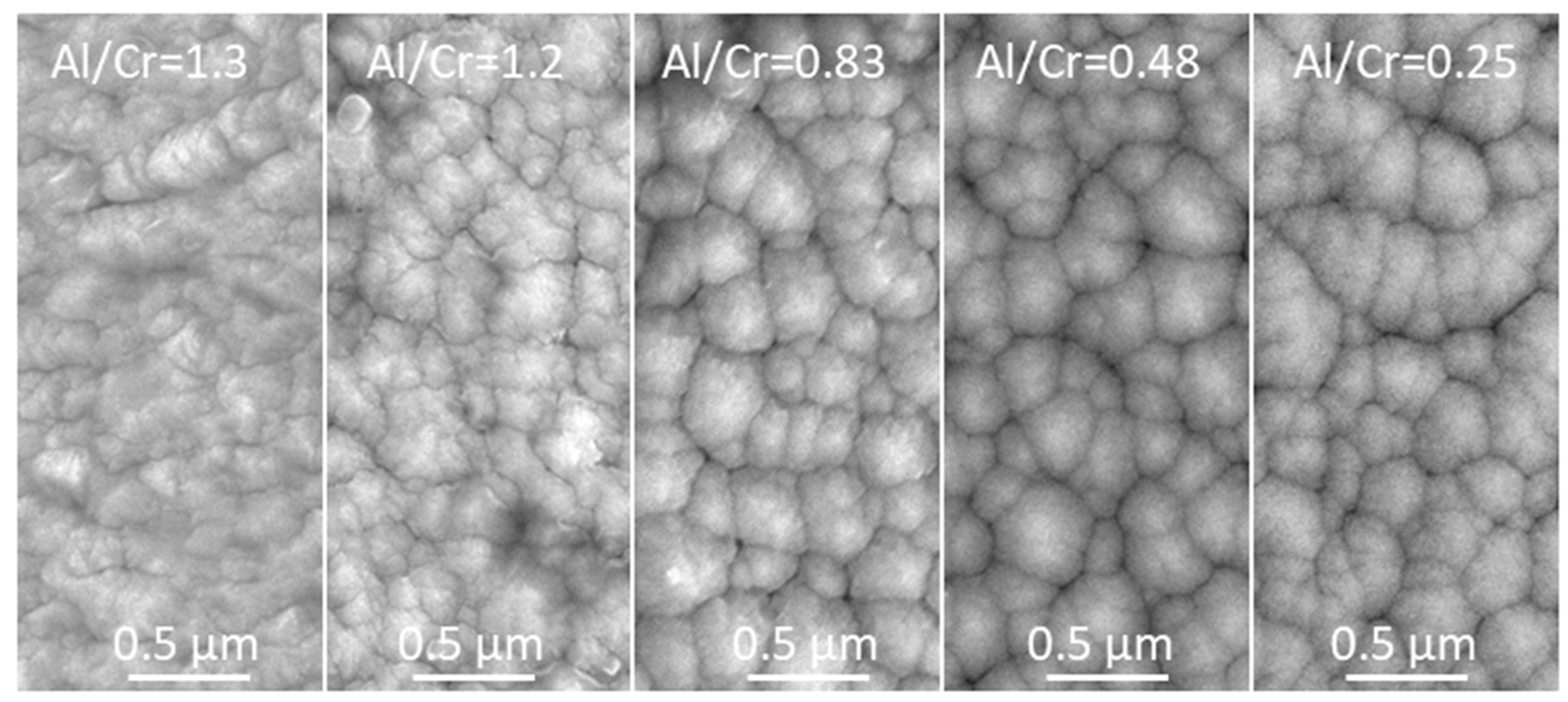
The topography of the (Cr,Al)N nanolayer coating was analyzed using SEM and AFM microscopes. The SEM images (Figure 5) show a granular morphology for all the as-deposited coatings. The faceted surface resulted from the columnar growth. The SEM topography image of all coatings shows a cauliflower-like topography. SEM images also reveal that all the Al-rich (Cr,Al)N nanolayer coatings are to some extent more compact and exhibit slightly smaller column tops on the surface compared to the Cr-rich ones.

Figure 5.
Top-view SEM images of as-deposited (Cr,Al)N nanolayer coatings with different Al/Cr atomic ratios.
More details about the coating surface topography were obtained via AFM microscopy. Figure 6 shows perspective-view AFM images of (Cr,Al)N nanolayer coatings with different Al/Cr atomic ratios deposited on the H11 tool steel substrates. The differences in coating surface topographies are not very significant. All coated samples exhibited similar values of surface roughness (Sa). The AFM surface roughness of both, Al-rich and Cr-rich coatings, are slightly smaller (around 20 nm) than for coatings with an intermediate composition (around 25 nm); see Figure 4b.
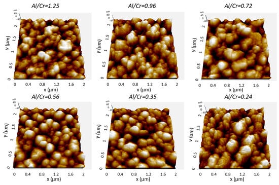
Figure 6.
Three-dimensional topography AFM images of as-deposited (Cr,Al)N nanolayer coatings with different Al/Cr atomic ratios deposited on the H11 tool steel substrates. Pay attention to the different z-scales on the AFM images.
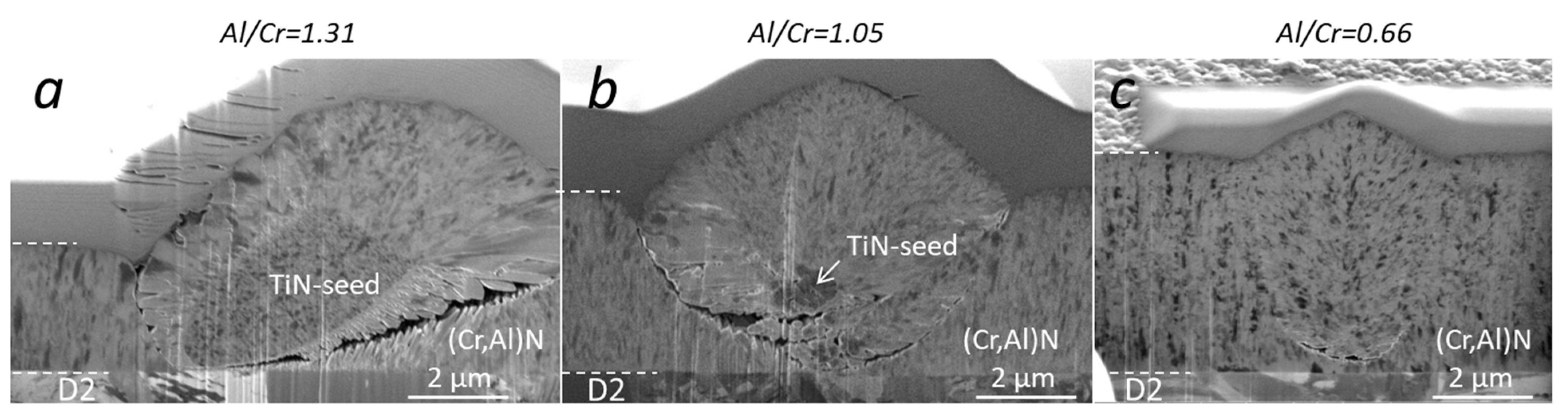
The microstructure of the (Cr,Al)N nanolayer coatings with three different Al/Cr atomic ratios can be seen in the SEM images of the FIB cross-sections (Figure 7). All coatings exhibit a dense and fine columnar microstructure. The SEM images were taken at the sites of nodular defects. The formation of defects resulted from seed particles present on the substrate surface (for example, TiN particles on Figure 7a,b, which probably originated from batching components coated with TiN in some of the previous batches). The columns are not single grains but are instead composed of smaller, predominantly equiaxed, grains. This is also confirmed by the cross-sectional TEM images (Figure 3) of as-deposited coatings, which prove that the characteristic diameter of the grains is 20–40 nm.

Figure 7.
SEM images of the FIB cross-sections of as-deposited (Cr,Al)N nanolayer coatings with different Al/Cr atomic ratios. SEM images were acquired at the sites of nodular defects using the ion beam.
3.1.5. Crystal Structure
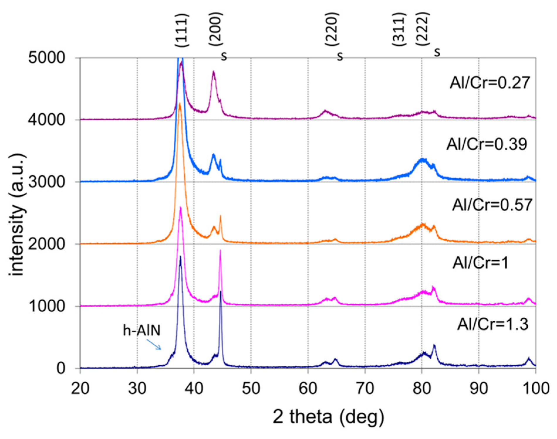
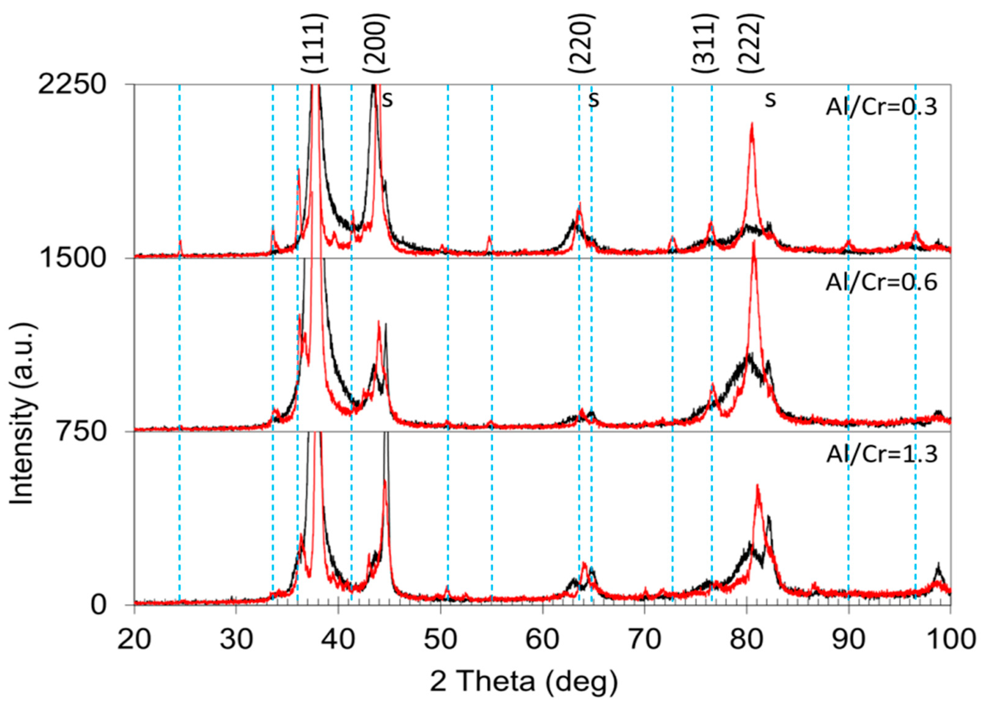
All as-deposited samples were characterized by XRD to evaluate the phase composition, crystallite size, crystallographic texture (preferred orientation) and microstrain. Figure 8 shows the stacked plot of the XRD spectra of the (Cr,Al)N nanolayer coatings with different Al/Cr atomic ratios. Using XRD, all the CrN/(Cr,Al)N/AlN coatings were found to crystallize in a face-centered-cubic (fcc) lattice with a B1 (NaCl) structure (JCPDS 11-0065 card). Additionally, in the XRD diffraction patterns of the (Cr,Al)N nanolayer coating with the Al/Cr atomic ratio higher than 1.3, a broad diffraction peak at ϑ = 33.3°appears, which could belong to the h-AlN (wurtzite) phase. All samples also show reflections from the tool steel substrate (marked with the letter “s”), which are much more pronounced in thinner coatings.

Figure 8.
Stacked plot of the XRD diffraction patterns of (Cr,Al)N coatings with different Al/Cr atomic ratios deposited on H11 tool steel substrates. The Miller indices indicate the diffraction peaks of the fcc (Cr,Al)N nitride phase (JCPDS 11-0065 card), the letters “s” indicate the peaks of the tool steel substrate, while the h-AlN diffraction peak is marked with an arrow.
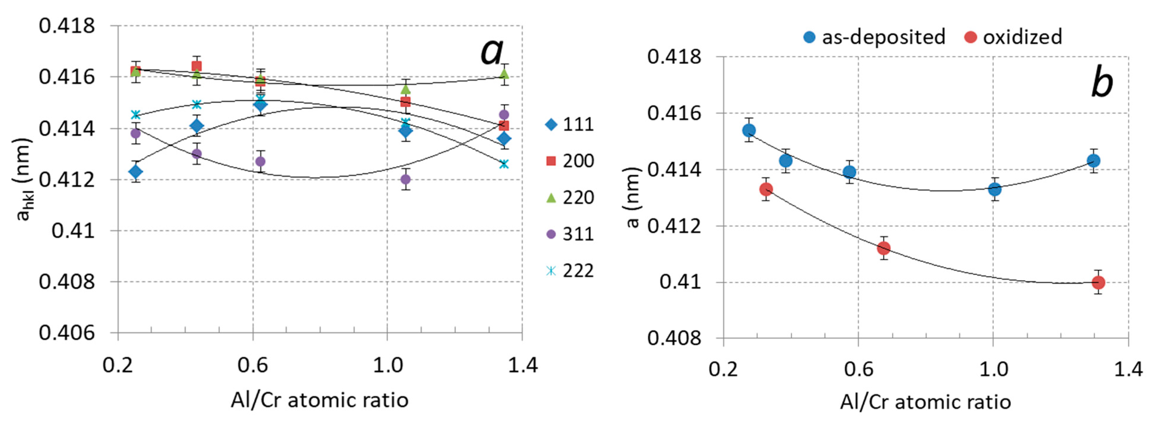
It can be observed that the diffraction peaks shift slightly with increased Al content. This shift is related to the formation of a substitutional solid solution in the fcc CrN phase. In Figure 9a, the lattice parameter ahkl of the (Cr,Al)N phase as calculated from the lattice spacing dhkl of the diffraction peaks is displayed as a function of the Al/Cr atomic ratio. In order to obtain the correct value of the lattice parameter (a), a systematic error that occurs during XRD measurement has to be removed. The largest cause for this error is displacement of a sample from the diffractometer axis, which can be minimized by using the extrapolation function [35]. In this procedure, we plot the lattice parameter ahkl as a function of the extrapolation function f(ϑ) = cos2ϑ/sin ϑ and fit the calculated values with a linear line. The intercept of this line with the y-axis (ϑ = 90°) presents the true value of the lattice parameter (a). The values of the lattice parameter determined in such a way for coatings with different compositions are given in Table 2 and are shown in Figure 9b. With an increasing ratio of Al/Cr, the lattice parameter decreases from 0.4143 nm for Cr-rich coating to 0.4133 nm for Al-rich ones. This reduction is expected since the aluminum atoms that dissolve in the fcc crystal structure of CrN are smaller than the chromium ones.
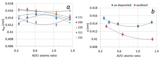
Figure 9.
(a) Lattice parameters ahkl of (Cr,Al)N coatings with different Al/Cr atomic ratios after deposition, (b) lattice parameter a of (Cr,Al)N coatings after deposition (blue circles) and after oxidation at 850 °C for two hours (red circles).
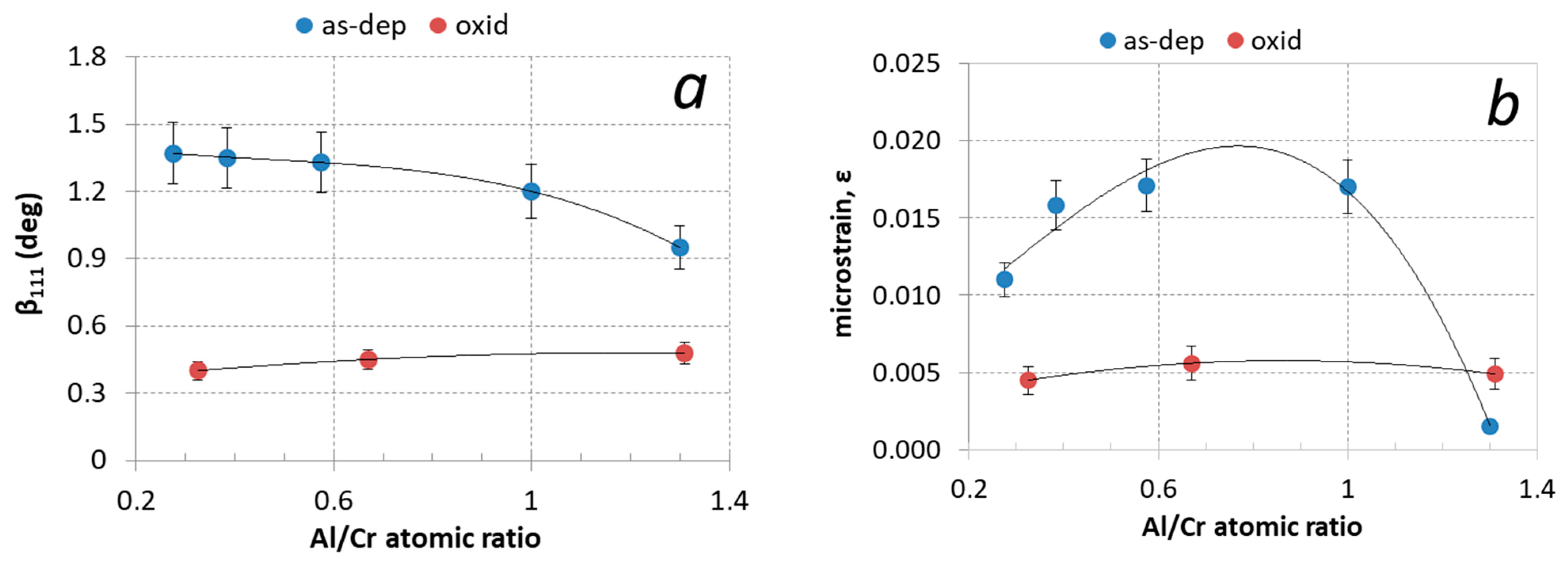
Aluminum content has a large effect on the diffraction peaks broadening (βhkl). The width of the diffraction peak is related to crystal grain size and the presence of inhomogeneous microstrains (ε). Microstrains were formed by the incorporation of Al atoms in the CrN-based fcc crystal structure as well as by the entrapment of nitrogen and argon ions in non-equilibrium interstitial (tetrahedral) lattice sites. The measured values of full width at half-maximum peak (111) are collected in Table 2 and shown in Figure 10a. The contributions of crystal grain size and microstrain to peak broadening can be extracted from the Williamson–Hall plot [36]. The slope of the line in this graph determines the microstrain (ε) in the coating, while the crystallite size (D) is estimated from the intercept of a plot with the y-axis using the Scherrer equation: β(ϑ) = kλ/Dcos ϑ (k is the constant—a dimensionless shape factor). Using this method we found that the average crystal grain size in the as-deposited Al-rich (Cr,Al)N nanolayer coating is around 10 nm, while it is around 30 nm in the Cr-rich ones (see Table 2). These values agree with the values determined from SEM and TEM images. The microstrain (ε) is the highest for coatings with the Al/Cr atomic ratio of about 0.75 and the lowest for Al-rich ones (see Figure 10b and Table 2).
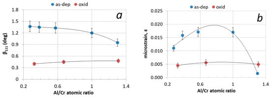
Figure 10.
(a) Full width at half maximum of (111) diffraction peak (β111) and (b) microstrain (ε) for (Cr,Al)N coatings with different Al/Cr atomic ratios after deposition (blue circles) and after oxidation at 850 °C for two hours (red circles).
3.2. Characterization of Oxidized (Cr,Al)N Coatings
3.2.1. Crystal Structure
The X-ray diffractograms in Figure 11 show the structural changes of the (Cr,Al)N coatings with different Al/Cr atomic ratios after oxidation at 850 °C for 120 min. After oxidation, the diffraction small peaks belonging to the Cr2O3 phase appeared. The formation of the crystalline Cr2O3 phase is much more intensive for coating with a low Al/Cr atomic ratio, while in the X-ray spectrum of Al-rich coatings diffraction peaks of the Cr2O3 phase are barely visible. This indicates that Al-rich coatings are rather oxidation-resistant at a temperature of 850 °C. No traces of aluminum oxides were detected.
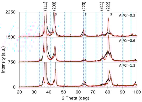
Figure 11.
Stacked plot of the XRD diffraction patterns of (Cr,Al)N coatings with different Al/Cr atomic ratios after oxidation of the samples at a temperature of 850 °C for 2 h (red spectra). The diffraction pattern of as-deposited coatings is added for comparison (black spectra). The Miller indices indicate the diffraction peaks of the fcc (Cr,Al)N nitride phase, the letters “s” indicate the peaks of the H11 tool steel substrate, while the dashed vertical lines indicate diffraction peaks belonging to the Cr2O3 phase (JCPDS card 038-1479).
In the X-ray spectra of the oxidized samples, the shift of the diffraction peaks of the remaining (Cr,Al)N phase towards larger angles as compared to the as-deposited state can be observed (Figure 11). The shift of the peaks belonging to the nitride phase to higher angles is most likely the result of the relaxation of the compressive stresses typical for sputter-deposited PVD coatings. However, not only did a shift of the peaks occur but also their narrowing (Figure 10a). In the samples exposed to oxidation at 850 °C, the lattice parameter of the remaining (Cr,Al)N layer decreased by more than 1% (see Figure 9b). This reduction could be attributed to the relaxation of the intrinsic stresses in the coating and the elimination of deposition-induced lattice defects (such as entrapped argon). Coating texture is also highly dependent on chemical composition. The as-deposited coatings with higher Al/Cr atomic ratio have a (111) texture, which gradually changes into (200) for coatings with higher Cr content.
The narrowing of the nitride phase diffraction peaks after oxidation of the sample at high temperatures is due to a change in the crystal size. The average size of the crystal grain, calculated from the Williamson–Hall plot using the Scherrer equation, increases to 60 nm for Al-rich coatings and 140 nm for Cr-rich ones.
After the oxidation at high temperatures, the (111) texture is still more dominant for all samples, especially for Al-rich coatings.
3.2.2. Weight Gain Measurements of the Oxidized Coatings
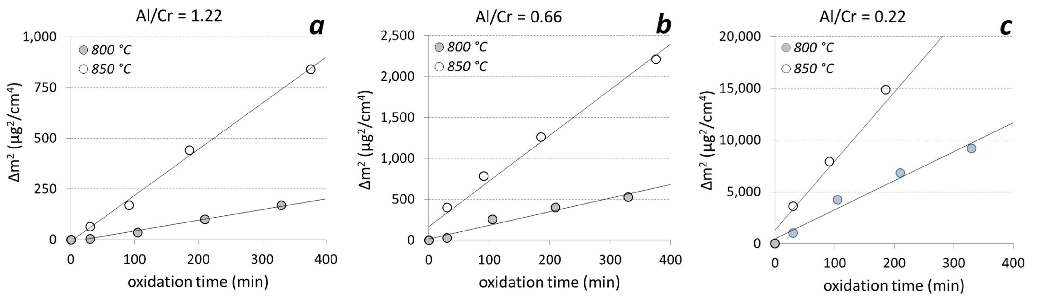
The coatings deposited on alumina were oxidized in a tube furnace with an oxygen flow at temperatures of 800 °C and 850 °C for 1100 min. After each oxidation step, we measured the weight gain. In the early stage of oxidation of Al-rich coatings at both oxidation temperatures, the growth of the oxide layer followed a parabolic law, as predicted by diffusion theory (Figure 12).
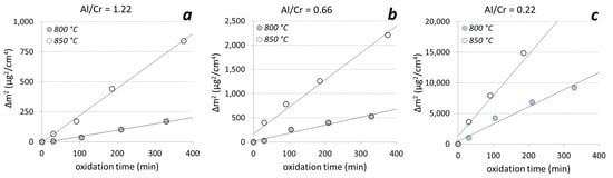
Figure 12.
The square of the weight gain of the (Cr,Al)N nanolayer coatings with different Al/Cr atomic ratios ((a) Al/Cr = 1.22, (b) Al/Cr = 0.66 and (c) Al/Cr = 0.22)) as a function of time at two different oxidation temperatures.
Thermogravimetric measurements of the (Cr,Al)N nanolayer coatings with three different Al/Cr atomic ratios showed that at the beginning (first 400 min at 850 °C) the oxide layer grew according to the parabolic diffusion law (Δm2 = kpt, where Δm is the weight gain, t is the oxidation time and kp is the parabolic rate constant). The onset temperature for the oxidation of the films decreased when Al was added to the CrN. For chromium content of more than 30 at. %, the oxidation process was much faster. After oxidation of Cr-rich coating at 850 °C for more than 400 min, the oxide layer cracked and delaminated.
For the temperatures where the oxidation proceeds parabolically, the activation energy for the oxidation Ea could be determined according to the Arrhenius formula (kp(T) = ko exp(−Ea/kT), where k is Boltzmann’s constant, T is the temperature, Ea is the activation energy for oxidation and ko is a temperature-independent constant which is related to the number of diffusion paths in the material. The results are given in Table 3. The activation energy for the oxidation of nanolayer coatings with Al/Cr atomic ratios 0.22, 0.66 and 1.3 are 1.81 ± 0.2 eV, 2.53 ± 0.3 eV and 3.06 ± 0.3 eV, respectively. The measured values of the ko constant are as follows: 7 × 10⁹, 1 × 10¹² and 9 × 10¹³ for Al/Cr atomic ratios 1.3, 0.66 and 0.22, respectively. In general, high activation energy for oxidation and a low constant ko means a good oxidation resistance of the coating. These results do not give a complete picture of the oxidation processes since they apply only under conditions where oxidation proceeds parabolically.
Table 3.
The activation energy for oxidation (Ea) and the parabolic oxidation constant (ko) of (Cr,Al)N nanolayer coatings with three different Al/Cr atomic ratios.
3.2.3. SEM and TEM Analysis of the Oxidized Coatings
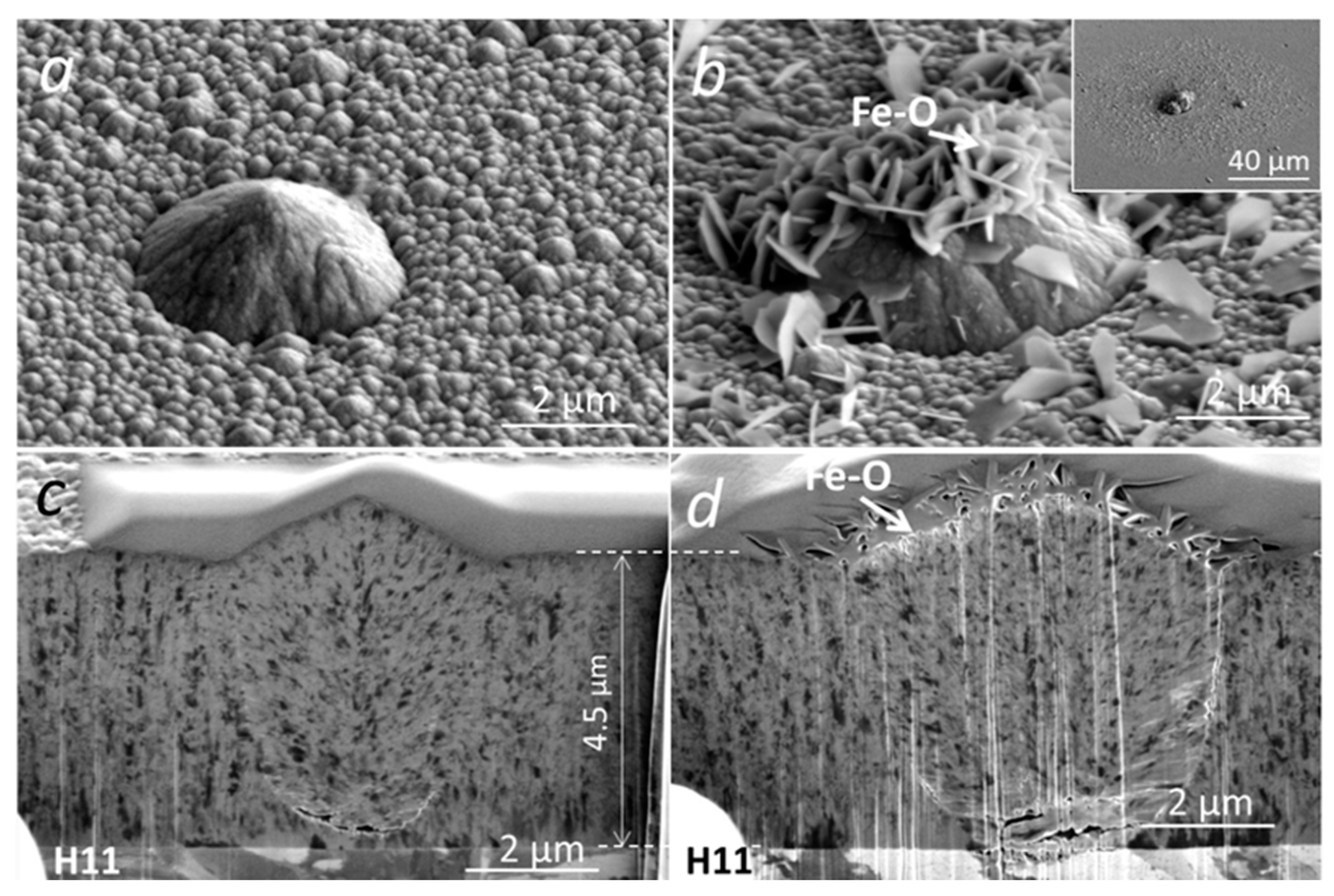
The initial oxidation tests of (Cr,Al)N coating with Al/Cr atomic ratio 0.6 deposited on H11 tool steel substrates were performed at 700 °C for 30 min. Under these conditions, we did not expect an intensive oxidation of coating, which is also confirmed by the SEM analysis (Figure 13). Namely, on the SEM images of the FIB cross-section, no oxide layer can be observed. However, we noticed a lot of oxidation products at the sites of several growth defects. EDS analysis shows that these products, which are spread around the nodular defects (see inset in Figure 13b), are iron oxides. The formation of such areas can be related to the diffusion of iron through pores (pinholes and voids) on the coating surface where nanoplates of iron oxide are formed. We have to mention that the coating is permeable only at the sites of those growth defects that extend through the entire coating thickness, while the diffusion intensity depends on how open the pathways to the substrate are. Even after short-term oxidation at 800 °C, no detectable oxidation of the (Cr,Al)N coating surface was observed. However, in this case, we again detected the iron oxide nanoplates at the sites of growth defects (see Figure 14). During the high-temperature oxidation of CrAlN and CrAlYN nanolayer coatings, diffusion of iron to the coating surface was also observed by Rojas et al. [37]. They found that at a temperature of 1000 °C, iron from the tool steel substrate diffuses along the column boundaries. However, they do not report about the diffusion of iron through pathways around growth defects.

Figure 13.
Top-view SEM and FIB cross-section images of nodular defects in the as-deposited (a,c) and oxidized (700 °C for 30 min) (Cr,Al)N coatings (b,d) with Al/Cr atomic ratio 0.6 deposited on H11 tool steel substrate.
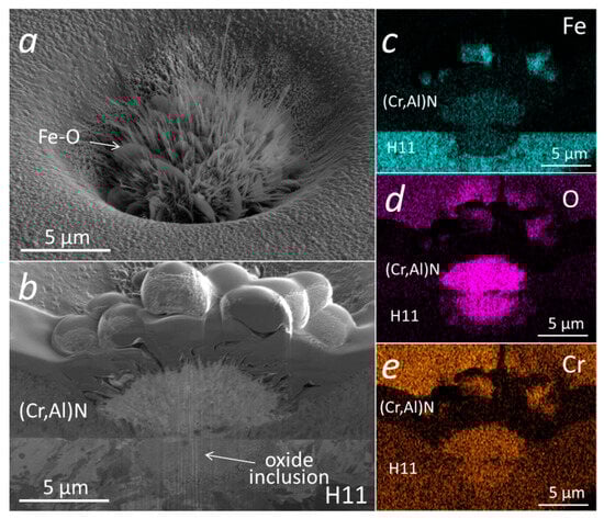
Figure 14.
Top-view SEM image (a) and SEM image of FIB cross-section (b) of a pinhole in a (Cr,Al)N nanolayer coating with Al/Cr atomic ratio 0.6 deposited on H11 tool steel substrate after short-term oxidation at 800 °C. The corresponding EDS elemental maps are presented in (c–e).
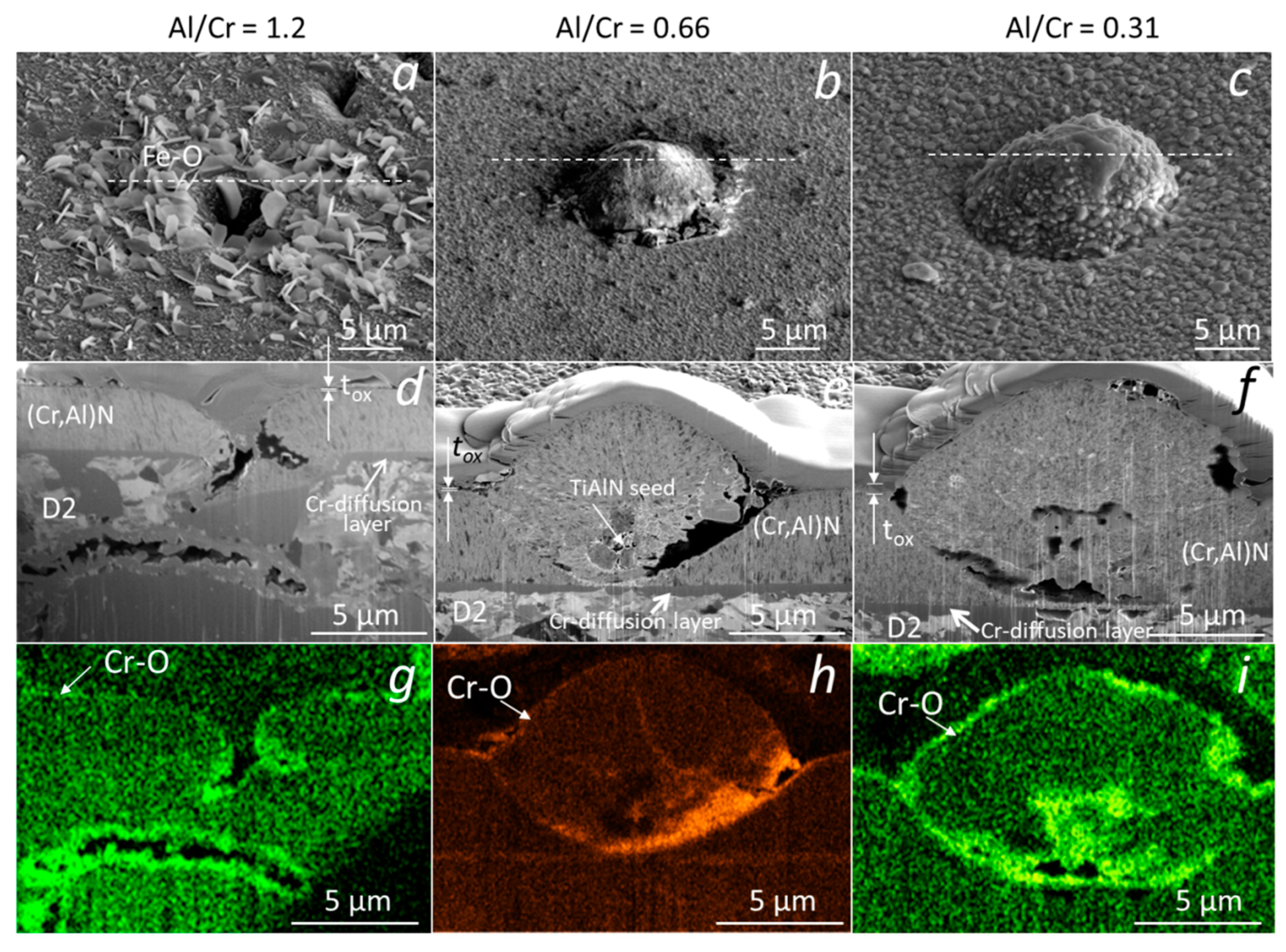
Similar analyses were performed on (Cr,Al)N nanolayer coatings with three Al/Cr atomic ratios (1.3, 0.84 and 0.25) deposited on the D2 tool steel substrate. All three samples were oxidized at 850 °C for 120 min. A continuous layer of chromium oxide was formed on the surface of all coatings (Figure 15). It is evident, that the chromium-rich coating oxidized much more strongly. The difference compared to the coatings deposited on the H11 tool steel substrates and oxidized at a lower temperature (700 °C, 30 min) is that no traces of iron oxides were observed at sites of nodular defects. However, they can be observed at sites of those pinholes that extend over the entire thickness of the coating. At the sites of defects, especially pinholes, there is an open path for the oxidation of the substrate. However, the subsequent oxidation process depends on the type of substrate and the oxidation temperature. In the case of substrates made of tool steel D2, which contains a relatively high concentration of chromium, a chromium diffusion layer was formed on the substrate surface during annealing at 850 °C for 120 min (see Figure 15d–f). This layer prevents the diffusion of iron to the substrate-coating interface and, consequently, no iron oxides can be formed at the sites of growth defects. However, they can be formed at the sites of pinholes that extend the entire coating (Figure 15a,d,g). Such pinholes are most often formed at sites of torn or cracked chromium carbides in the D2 substrate. On the other side, the intensive oxidation of the H11 substrate, protected with the same coating, was observed already at a temperature of 700 °C for 30 min. At these annealing conditions of H11 tool steel, no chromium diffusion layer was formed and, therefore, a strong oxidation of the substrate occurred at the sites of growth defects.
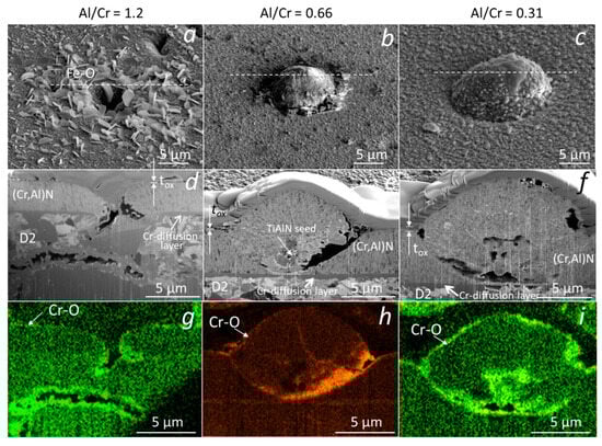
Figure 15.
Top-view SEM and FIB cross-section images of nodular defects in the oxidized (850 °C, 120 min) (Cr,Al)N nanolayer coatings (b,d) with Al/Cr atomic ratios 1.2 (a,d,g), 0.66 (b,e,h) and 0.31 (c,f,i), deposited on D2 tool steel substrate. The corresponding EDS elemental maps of oxygen are added (g–i).
The microstructure of the oxidized (Cr,Al)N coatings with three different Al/Cr atomic ratios was analyzed by TEM. The coatings were deposited on the D2 tool steel substrate and oxidized in air at 850 °C for 120 min. The FIB lift-out technique was used for the preparation of the lamella. Figure 16 shows the bright-field cross-sectional TEM images of the oxide scales. The TEM analysis reveals that the Al-rich oxide zone is composed of an outer, crystalline layer and an inner, porous layer. The oxide–coating interface is rough and wavy. Using the EDS technique, we confirmed that the outer oxide layer is chromium oxide, while the inner one is composed of mixed Al-Cr oxide. In the case of Cr-rich coating, the oxide scale is composed only of chromium oxide. The thicknesses of the Cr-O layer is about 49 nm, 132 nm and 600 nm, for (Cr,Al)N coatings with Al/Cr atomic ratios 1.3, 0.66 and 0.33, respectively. The thickness of mixed Cr-Al oxide is 44 nm and 10 nm for (Cr,Al)N coatings with Al/Cr atomic ratios 1.3 and 0.66, respectively. The TEM observations revealed that the nanolayered coating structure was not destroyed by the heat treatment.
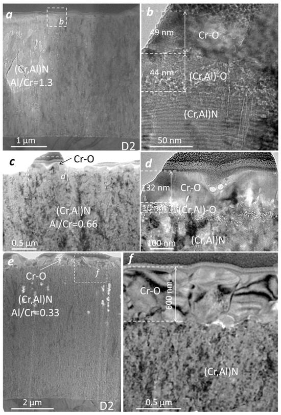
Figure 16.
Cross-sectional TEM images of nanolayer (Cr,Al)N coating with three different atomic ratios: Al/Cr = 1.3 (a,b), Al/Cr = 0.66 (c,d) and Al/Cr = 0.33 (e,f).
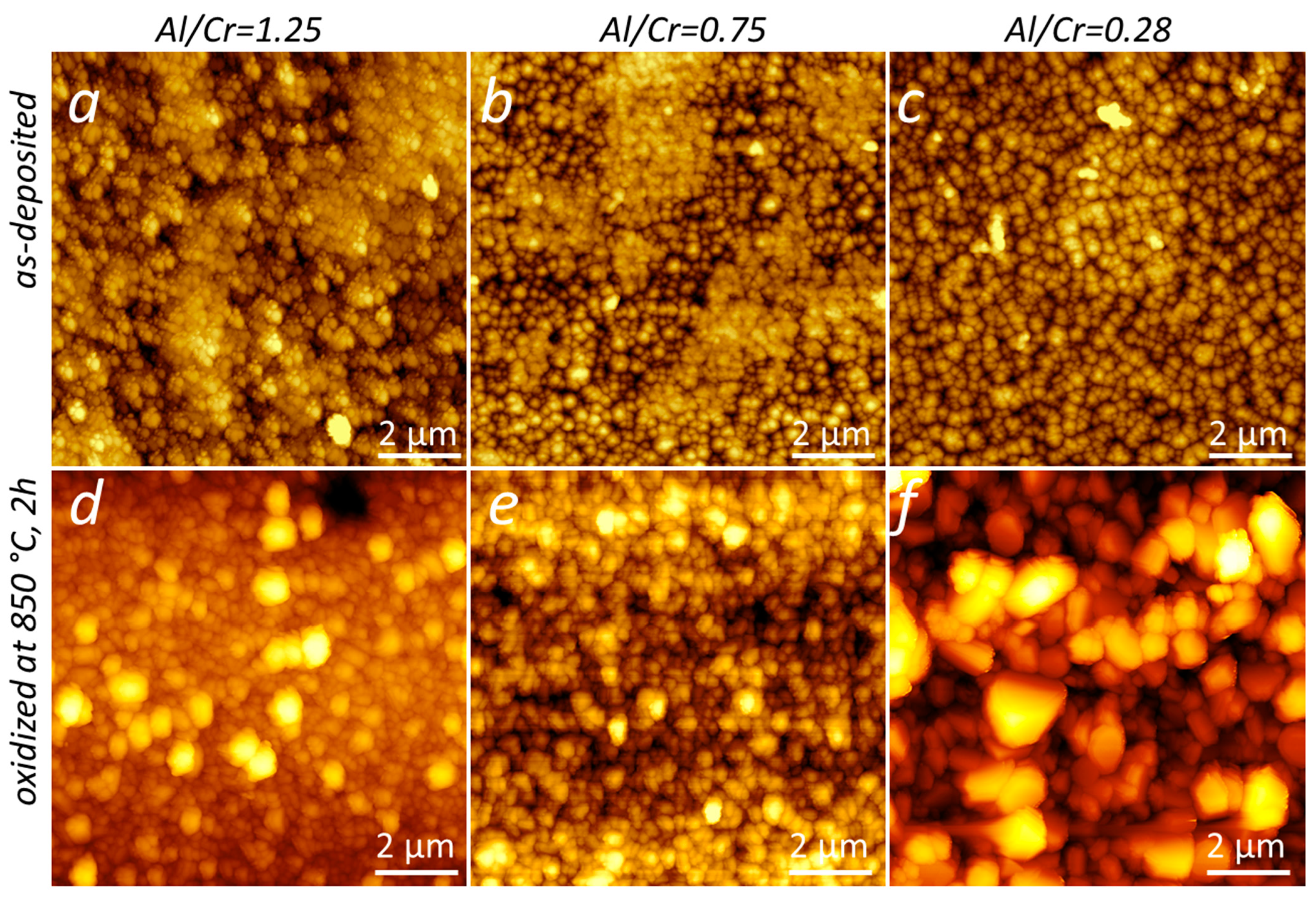
Large crystal grains on the surface of oxidized samples can also be seen in AFM images (Figure 17). As a result, the surface roughness also increases. The surface roughnesses of the Al-rich and Cr-rich coatings, determined from AFM images, were 55 nm and 100 nm, respectively.
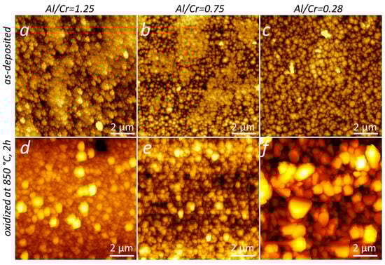
Figure 17.
AFM images of the surface topography of (Cr,Al)N nanolayer coating with three different Al/Cr atomic ratios deposited on the D2 tool steel substrates: as-deposited (a–c) and oxidized at 850 °C for 120 min (d–f). The frame size is 10 µm × 10 µm.
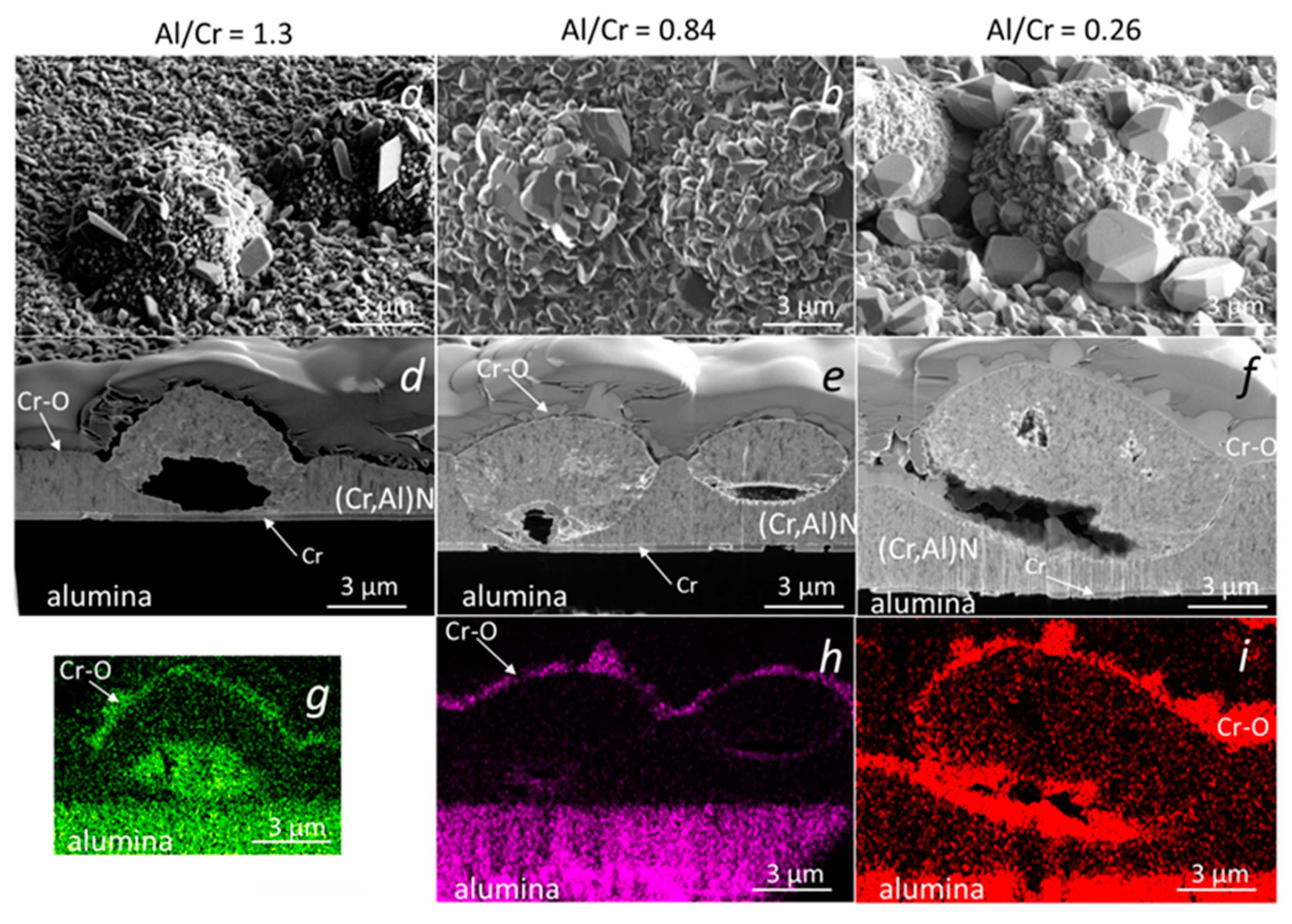
For some applications (e.g., gas turbine engines, die casting, plastic molding), the long-term oxidation resistance of (Cr,Al)N coating is also very important. In this study, we analyzed the oxidation behavior of (Cr,Al)N nanolayer coatings with three different Al/Cr atomic ratios deposited on the alumina substrate and oxidized at a temperature of 850 °C for 1200 min. Figure 18 shows SEM images of FIB cross-sections of the nodular defects in the (Cr,Al)N nanolayer coatings with Al/Cr atomic ratios 1.3 (a,d,g), 0.84 (b,e,h) and 0.25 (c,f,i), respectively. Again, the Cr-rich coating oxidized much more strongly than the Al-rich one. On the surface of such a coating, chromium oxide crystals grew with dimensions up to a few micrometers. From the corresponding EDS maps of oxygen, we can see that the oxide layer also formed in the voids around the nodular defects. A thin chromium layer, which can be seen in the SEM image of the FIB cross-sections, was previously sputter-deposited on polished alumina substrate to ensure electrical contact during the deposition process. It is evident that this layer did not affect the oxidation process.

Figure 18.
SEM top view (a–c) and FIB cross-section images of nodular defects in (Cr,Al)N nanolayer coatings with Al/Cr atomic ratios of 1.3 (a,d,g), 0.84 (b,e,h) and 0.26 (c,f,i) deposited on polished alumina substrates after oxidation at 850 °C for 1200 min. The corresponding maps of oxygen are also added (g–i).
4. Conclusions
(Cr,Al)N nanolayer coatings with different Al/Cr atomic ratios were prepared via magnetron sputtering in the same batch on different substrates (H11 and D2 tool steels, alumina) using triangle-like segmented Cr/Al targets. Within this study, the crystal structure, microstructure, surface topography, mechanical properties and oxidation resistance of these coatings were investigated and discussed in detail. We were particularly interested in the impact of growth defects on their oxidation stability. The main results of the study can be summarized as follows:
- We showed that by using triangle-like segmented targets for an industrial-scale magnetron deposition system, a series of hard coatings with different compositions and modulation periods in one batch can be prepared; this approach greatly shortens and simplifies the development of a new multicomponent hard coating.
- Sputter-deposited nanolayer (Cr,Al)N hard coatings with Al/Cr atomic ratios in the range of 0.27 to 1.3 exhibit fcc cubic structure, which is typical of transition metal nitrides. Only in the case of a high atomic ratio (Al/Cr = 1.3), is the h-AlN phase also detected.
- During high-temperature oxidation, a protective dense chromium oxide scale is formed on the top of the oxide scale. The oxide layer thickness increased, following a parabolic-type growth, with an activation energy of 3.06 eV for the Al-rich (Cr,Al)N coatings and 1.81 eV for Cr-rich ones. The thickness of the oxide layer depends on the Al/Cr atomic ratio; it is largest for the Cr-rich layer and smallest for the Al-rich one.
- The structure of the oxidation scales depends on the Al/Cr atomic ratio: for Al-rich coatings, the oxidation scales consisted of both a Cr-O outside layer and a mixed (Cr,Al)-oxide inner layer, while only a Cr-O layer was observed for Cr-rich coatings.
- A dense Cr-based oxide scale acted as a barrier layer, blocking the outward diffusion of metallic atoms and retarding the inward diffusion of oxygen into the coating.
- We found that the oxidation of the substrate occurs at the growth defect sites at a temperature which is well below the temperature for the initiation of the (Cr,Al)N coating oxidation. The oxidation process at the sites of defects largely depends on the type of substrate material.
Author Contributions
A.D.: conceptualization, investigation, preparation of specimen for TEM characterization, SEM and FIB analysis, weight gain measurements and manuscript writing; D.K.: design of experiments, methodology and manuscript review; P.T.: design of experiments, methodology, funding acquisition and manuscript review; A.M.: design of experiment and manuscript review; P.P.: design of experiments, 3D profilometry, interpretation of experimental results and manuscript writing; M.Č.: project administration, funding acquisition and manuscript review; M.P.: manuscript review. All authors have read and agreed to the published version of the manuscript.
Funding
This work was supported by the Slovenian Research Agency (program P2-0082, project J2-2509) and by the Ministry of Science, Technological Development and Innovation, Republic of Serbia, through project no. 451-03-47/2023-01/200156 “Innovative scientific and artistic research from the FTS (activity) domain”. We also acknowledge funding from the European Regional Development Funds (CEEN Nanocenter): OP13.1.1.2.02.006.
Institutional Review Board Statement
Not applicable.
Informed Consent Statement
Not applicable.
Data Availability Statement
Data are contained within the article.
Acknowledgments
The authors would also like to thank Jožko Fišer and Domen Korbar for technical assistance.
Conflicts of Interest
The authors declare no conflict of interest.
References
- Vetter, J.; Eriksson, A.O.; Reiter, A.; Deflinger, V.; Kalss, W. Quo Vadis: AlCr-Based Coatings in Industrial Applications. Coatings 2021, 11, 344. [Google Scholar] [CrossRef]
- Tillman, W.; Dias, N.F.L.; Stangier, D. Effect of Hf on the microstructure, mechanical properties, and oxidation behavior of sputtered CrAlN films. Vacuum 2018, 154, 208–213. [Google Scholar] [CrossRef]
- Knotek, O.; Atzor, M.; Barimani, C.; Jungblut, F. Development of low temperature ternary coatings for high wear resistance. Surf. Coat. Technol. 1990, 42, 21–28. [Google Scholar] [CrossRef]
- Hoffmann, S.; Jehn, H.A. Oxidation behaviour of CrNx and (Cr,Al)N hard coatings. Werkst. Korros. 1990, 47, 756–760. [Google Scholar] [CrossRef]
- Gerth, J.; Larsson, M.; Wiklund, U.; Riddar, F.; Hogmark, S. On the wear of PVD-coated HSS hobs in dry gear cutting. Wear 2009, 266, 444–452. [Google Scholar] [CrossRef]
- Kalss, W.; Reiter, A.; Derflinger, V.; Gey, C.; Endrino, J.L. Modern coatings in high performance cutting applications. Int. J. Refract. Met. Hard Mater. 2006, 24, 399–404. [Google Scholar] [CrossRef]
- Lugscheider, E.; Bobzin, K.; Hornig, T.; Maes, M. Investigation of the residual stresses and mechanical properties of (Cr,Al)N arc PVD coatings used for semi-solid metal (SSM) forming dies. Thin Solid. Film. 2002, 420-421, 318–323. [Google Scholar] [CrossRef]
- Bobzin, K.; Bagcivan, N.; Goebbels, N.; Yilmaz, K.; Hoehn, B.R.; Michaelis, K.; Hochmann, M. Lubricated PVD CrAlN and WC/C coatings for automotive applications. Surf. Coat. Technol. 2009, 204, 1097–1101. [Google Scholar] [CrossRef]
- Bobzin, K.; Brögelmann, T.; Kalscheuer, C.; Liang, T. High-rate deposition of thick (Cr,Al)ON coatings by high speed physical vapor deposition. Surf. Coat. Technol. 2017, 322, 152–162. [Google Scholar] [CrossRef]
- Vetter, J.; Lugscheider, E.; Guerreiro, S.S. (Cr:Al)N coatings deposited by the cathodic vacuum are evaporation. Surf. Coat. Technol. 1998, 98, 1233–1239. [Google Scholar] [CrossRef]
- Kawate, M.; Hashimoto, A.K.; Suzuki, T. Oxidation resistance of Cr1−xAlxN and Ti1−xAlxN films. Surf. Coat. Technol. 2003, 165, 163–167. [Google Scholar] [CrossRef]
- Lin, J.; Mishra, B.; Moore, J.J.; Sproul, W.D. A study of the oxidation behavior of CrN and CrAlN thin films in air using DSC and TGA analyses. Surf. Coat. Technol. 2008, 202, 3272–3283. [Google Scholar] [CrossRef]
- Mayrhofer, P.H.; Rachbauer, R.; Holec, D.; Rovere, F.; Schneider, J.M. Protective Transition Metal Nitride Coatings. In Comprehensive Materials Processing; Newnes: Newton, MA, USA, 2014; pp. 355–388. [Google Scholar]
- Willmann, H.; Mayrhofer, P.H.; Persson, P.H.A.; Reiter, A.E.; Hultman, L.; Mitterer, C. Thermal stability of Al–Cr–N hard coatings. Scr. Mater. 2006, 54, 1847–1851. [Google Scholar] [CrossRef]
- Lin-qing, H.; Chen, L.; Xu, Y.-X.; Du, Y. Thermal stability and oxidation resistance of Cr1−xAlxN coatings with single phase cubic structure. J. Vac. Sci. Technol. A 2015, 33, 061513. [Google Scholar]
- Liu, C.B.; Pei, W.; Huang, F.; Chen, L. Improved mechanical and thermal properties of CrAlN coatings by Si solid solution. Vacuum 2016, 125, 180–184. [Google Scholar] [CrossRef]
- Polcar, T.; Cavaleiro, A. High temperature properties of CrAlN, CrAlSiN and AlCrSiN coatings—Structure and oxidation. Mater. Chem. Phys. 2011, 129, 195–201. [Google Scholar] [CrossRef]
- Drnovšek, A.; de Figueiredo, R.M.; Vo, H.; Xia, A.; Vachhani, S.J.; Kolozsvári, S.; Hosemann, P.; Franz, R. Correlating high temperature mechanical and tribological properties of CrAlN and CrAlSiN hard coatings. Surf. Coat. Technol. 2019, 372, 361–368. [Google Scholar] [CrossRef]
- Hu, C.; Chen, L.; Lou, Y.; Zhao, N.; Yue, J. Influence of Si content on the microstructure, thermal stability and oxidation resistance of TiAlSiN/CrAlN multilayers. J. Alloys Compd. 2021, 855, 157441. [Google Scholar] [CrossRef]
- Bobzin, K.; Bagcivan, N.; Immich, P.; Bolz, S.; Cremer, R.; Leyendecker, T. Mechanical properties and oxidation behaviour of (Al,Cr)N and (Al,Cr,Si)N coatings for cutting tools deposited by HPPMS. Thin Solid. Film. 2008, 517, 1251–1256. [Google Scholar] [CrossRef]
- Tian, J.L.; Hu, C.; Chen, L.; Lou, Y.M.; Zhao, N.N. Structure, mechanical and thermal properties of Y-doped CrAlN coatings. Trans. Nonferrous Met. Soc. China 2021, 31, 2740–2749. [Google Scholar] [CrossRef]
- Rovere, F.; Mayrhofer, P.H. Thermal stability and thermo-mechanical properties of magnetron sputtered Cr-Al-Y-N coatings. J. Vac. Sci. Technol. A 2007, 26, 29–35. [Google Scholar] [CrossRef]
- Chen, L.; Liu, Z.Q.; Xu, Y.X.; Du, Y. Influence of Zr on structure, mechanical and thermal properties of CrAlN coatings. Surf. Coating. Technol. 2015, 275, 289–295. [Google Scholar] [CrossRef]
- Forsén, R.; Johansson, M.P.; Odén, M.; Ghafoor, N. Effects of Ti alloying of AlCrN coatings on thermal stability and oxidation resistance. Thin Solid. Films 2013, 534, 394–402. [Google Scholar] [CrossRef]
- Chun, H.; Yu, X.; Chen, L.; Pei, F.; Zhang, L.J.; Du, Y. Structural, mechanical and thermal properties of CrAlNbN coatings. Surf. Coat. Technol. 2018, 349, 894–900. [Google Scholar]
- Chun, H.; Yu-Xiang, X.; Li, C.; Fei, P.; Yong, D. Mechanical properties, thermal stability and oxidation resistance of Ta-doped CrAlN coatings. Surf. Coat. Technol. 2019, 368, 25–32. [Google Scholar]
- Tillmann, W.; Kokalj, D.; Stangier, D.; Paulus, M.; Sternemann, C.; Tolan, M. Investigation on the oxidation behavior of AlCrVxN thin films by means of synchrotron radiation and influence on the high temperature friction. Appl. Surf. Sci. 2018, 427, 511–521. [Google Scholar] [CrossRef]
- Hu, C.; Chen, L.; Moraes, V. Structure, mechanical properties, thermal stability and oxidation resistance of arc evaporated CrAlBN coatings. Surf. Coat. Technol. 2021, 417, 127191. [Google Scholar] [CrossRef]
- Bagcivan, N.; Bobzin, K.; Theiß, S. (Cr1−xAlx)N: A comparison of direct current, middle frequency pulsed and high power pulsed magnetron sputtering for injection molding components. Thin Solid. Film. 2013, 528, 180–186. [Google Scholar] [CrossRef]
- Panjan, P.; Drnovšek, A.; Dražić, G. Influence of Growth Defects on the Oxidation Resistance of Sputter-Deposited TiAlN Hard Coatings. Coatings 2021, 11, 123. [Google Scholar] [CrossRef]
- Terek, P.; Kukuruzović, D.; Kovačević, L.; Miletić, A.; Terek, V.; Škorić, B.; Panjan, P.; Čekada, M. The Influence of CrAlN Coating Chemical Composition on Soldering Resistance in Contact with Al-Si-Cu Alloy. Mater. Proc. 2020, 2, 28. [Google Scholar]
- Andersen, H.H.; Bay, H.L. Sputtering by Particle Bombardment, 1st ed.; Behrisch, R., Ed.; Springer-Verlag: New York, NY, USA, 1981; pp. 145–218. [Google Scholar]
- Mahne, N.; Čekada, M.; Panjan, M. Total and Differential Sputtering Yields Explored by SRIM Simulations. Coatings 2022, 12, 1541. [Google Scholar] [CrossRef]
- Mayrhofer, P.H.; Music, D.; Reeswinkel, T.; Fuß, H.-G.; Schneider, J.M. Structure, elastic properties and phase stability of Cr1–xAlxN. Acta Mater. 2008, 56, 2469–2475. [Google Scholar] [CrossRef]
- Waseda, Y.; Matsubara, E.; Shinoda, K. ; X-ray Diffraction Crystallography; Springer: New York, NY, USA, 2011; Chapter 4; pp. 120–121, 145–152. [Google Scholar]
- Williamson, G.K.; Hall, W.H. X-ray line broadening from filed aluminium and wolfram. Acta Metall. 1953, 1, 22–31. [Google Scholar] [CrossRef]
- Rojas, T.C.; Domínguez-Meister, S.; Brizuela, M.; Sánchez-López, J.C. High-temperature oxidation of CrAlYN coatings: Implications of the presence of Y and type of steel. Surf. Coat. Technol. 2018, 354, 203–213. [Google Scholar] [CrossRef]


Disclaimer/Publisher’s Note: The statements, opinions and data contained in all publications are solely those of the individual author(s) and contributor(s) and not of MDPI and/or the editor(s). MDPI and/or the editor(s) disclaim responsibility for any injury to people or property resulting from any ideas, methods, instructions or products referred to in the content. |
© 2023 by the authors. Licensee MDPI, Basel, Switzerland. This article is an open access article distributed under the terms and conditions of the Creative Commons Attribution (CC BY) license (https://creativecommons.org/licenses/by/4.0/).