Article

Precise Characterization of CNF-Coated Microfibers Using Transmission Electron Microscopy

by
Denis V. Korneev
1,
Irina V. Krasnikova
2,
Sofya D. Afonnikova
3,
Aleksey A. Vedyagin
3 and
Ilya V. Mishakov
3,*
1
Department of Biochemistry and Molecular Biology, Monash University, Melbourne, VIC 3800, Australia
2
Center for Electrochemical Energy Storage, Skolkovo Institute of Science and Technology, 143026 Moscow, Russia
3
Boreskov Institute of Catalysis, 630090 Novosibirsk, Russia
*
Author to whom correspondence should be addressed.
Coatings 2023, 13(2), 256; https://doi.org/10.3390/coatings13020256
Submission received: 22 December 2022 / Revised: 18 January 2023 / Accepted: 19 January 2023 / Published: 21 January 2023
(This article belongs to the Special Issue Perspective Coatings for Optical Materials Modifications)

Abstract

:
The synthesis and characterization of fibrous materials with a hierarchical structure are of great importance for materials sciences. Among this class of materials, microfibers of different natures coated with carbon nanofibers attract special interest. Such coating modifies the surface of microfibers, makes it rougher, and thus strengthens its interaction with matrices being reinforced by the addition of these microfibers. In the present work, a series of hierarchical materials based on carbon microfibers, basalt microfibers, and fiberglass cloth coated with up to 50 wt% of carbon nanofibers was synthesized via the catalytic chemical vapor deposition technique. The initial items were impregnated with an aqueous solution of nickel nitrate and reduced in a hydrogen flow. Then, the catalytic chemical vapor deposition process using C2H4 or C2H4Cl2 as a carbon source was carried out. A simple and cost-effective technique for the preparation of the samples of hierarchical materials for transmission electron microscopy examination was developed and applied for the first time. The proposed method of sample preparation for sequential TEM visualization implies an ultrasonic treatment of up to four samples simultaneously under the same conditions by using a special sample holder. As was found, the relative strength of carbon nanofibers coating the surface of microfibers decreases in the order of CNF/CMF > CNF/BMF > CNF/FGC. Two effects of the ultrasonic action on the carbon coating were revealed. First, strongly bonded carbon nanofibers undergo significant breakage. Such behavior is typical for carbon and basalt microfibers. Secondly, carbon nanofibers can be completely detached from the microfiber surface, as was observed in the case of fiberglass cloth. In the case of CNF/CMF material, the graphitized surface of carbon microfiber is coherent with the structure of carbon nanofiber fragments grown on it, which explains the highest adhesion strength of the carbon nanolayer coated on carbon microfibers.

1. Introduction

Nowadays, fibrous materials with a hierarchical structure are subject to high demand for use in the field of materials sciences. Thus, they are often applied as reinforcing agents for the production of various composite materials with improved properties and prolonged operating times [1,2,3,4,5]. For example, the application of carbon microfibers as fillers makes it possible to produce lightweight materials with enhanced mechanical strength [6]. Among the most demanded and promising hierarchical materials, the ones based on carbon or mineral fibers should be mentioned especially. Their introduction into various matrices allows controlling both physical and mechanical properties in a wide range [1,6,7,8].
It is well known that the surface properties of the fillers used for reinforcement purposes are the factor defining the overall efficiency of the reinforcement process. As a rule, the surface of as-produced microfibers is very smooth. Therefore, the reinforcing effect is implicitly expressed in this case. Contrarily, the modification of the surface of microfibers with carbon nanostructures (e.g., carbon nanofibers or carbon nanotubes) makes it rough and strengthens its interaction with the matrix being reinforced [9,10,11,12,13]. As a result of such modification, a layer of carbon nanofibers (CNFs) is formed on the surface, which affects its adhesive behavior [14,15,16,17].
It is important to note that the application areas of such hierarchical materials are not limited only to reinforced composites. For instance, within the nanocomposite smart coating concept, both active and passive protection performances are reported [18]. In addition, they are applicable as catalysts for various heterogeneous processes [11] and electrochemistry [19,20]. The advantage of these systems is that the dispersed metal particles are fixed on the tips of the formed carbon nanofibers, which makes them entirely accessible for the reagents and mechanically protected from sintering.
The most important parameter characterizing the properties of composite materials is the adhesion strength between the surface of microfibers and CNF [21,22]. A typical diameter of microfibers lies between 3 and 20 μm, while for CNF it is often less than 100 nm. Thereby, it is difficult to measure the adhesion strength directly. Only two methods of direct measurement for such hybrid systems are presented in the literature: a mechanical detachment of single carbon nanofibers using the tip of an atomic force microscope (AFM) [14] and a single fiber pull-out test using a tensile stress testing system [23] or an AFM [15]. These state-of-the-art methods claim some extremely precise manipulations and the results dependent on such parameters as AFM cantilever stiffness, tip geometry, and parameters of interaction between the tip and the CNF-coated surface. On the other hand, the transmission electron microscopy (TEM) technique is very simple in operation and can be applied for routine studies using a conventional transmission electron microscope without any modifications. Therefore, TEM analysis is one of the most important and often used methods for nanomaterials characterization. It provides high-resolution visualization (2D or 3D by using electron tomography technique), local element analysis, micro-diffraction, and even crystallographic information. Commercially available TEM sample holders are suitable for performing in situ electrical, mechanical, and thermal experiments [24]. Modern high-performance charge-coupled device (CCD) cameras can acquire pictures with a high spatial and temporal resolution, thus making it possible to record nanoscale “movies” during experiments [25]. At the same time, the advanced instruments are very expensive and narrowly specialized which dramatically limits their availability. In addition, there are some requirements for TEM samples. Thus, the sample should be thin enough (typically, about 100 nm) to be transparent for the electron beam [26], and special preparation is required to make the specimen suitable for TEM examination. There are many different preparative techniques, which are more or less commonly used in routine practice, but they all are designed to preserve the original sample structure [27].
The main goal of the present study is the development of a simple and cost-effective method for the preparation of fibrous hierarchical materials, which can be used for the estimation of their mechanical strength at micro- and nanoscale by the comparative visualization of intact and ultrasound-treated surfaces for the same fiber fragment. The developed technique can be used with all conventional TEM instruments and does not require any expensive equipment, such as TEM holders for in-situ microscopy. In the nearest future, it can be broadly used in routine studies of any fibrous nanomaterials with a hierarchical structure.

2. Materials and Methods

2.1. Materials

The following fibrous materials were used in the present study: chopped carbon microfiber (CMF, type UKN-M 5000, Argon LLC, Saratov, Russia); chopped basalt microfiber (BMF, type SV-B-13-4S, Basalt Materials Plant LLC, Pokrovsk, Russia); fiberglass cloth (FGC, type KT-1000, Steklovolokno Ltd., Ekaterinburg, Russia). Ethylene (Nizhnekamskneftekhim, Nizhnekamsk, Russia) and 1,2-dichloroethane (1,2-DCE, C2H4Cl2, chemically pure, Component-Reactiv, Moscow, Russia) were used for the CNF synthesis over the surface of microfibers via catalytic chemical vapor deposition (CCVD).

2.2. Preparation and Characterization of Hierarchical Materials

The designation of the synthesized hierarchical materials and their preparation conditions are summarized in Table 1.
In order to obtain hierarchical materials, initial microfibrous samples were coated with CNF by means of the CCVD process. In general, the preparation procedure includes two steps: deposition of dispersed metal particles (Ni) on the microfibers’ surface; and CCVD process of a carbon source (ethylene or 1,2-dichloroethane). The deposition of nickel particles was performed by an incipient wetness impregnation of microfibers with an aqueous solution of nickel nitrate (Reachem, Moscow, Russia). The metal loading in all the cases was 2.5 wt% with regard to metallic Ni. Then, the samples were dried and calcined at 350 °C for 1 h. The calcination procedure provides the decomposition of the deposited nickel nitrate and the formation of nickel oxide (NiO).
At the next stage, the samples with supported NiO particles were placed into a vertical quartz reactor and heated in an argon flow (20 L/h) to the reaction temperature (500 or 600 °C). Then, the reactor was fed with hydrogen (6 L/h) for 20 min in order to reduce NiO and obtain metallic nickel. The samples with dispersed nickel particles were then brought to contact with the reaction mixture containing C2H4 or C2H4Cl2 to produce the coating layer of CNF over the surface of microfibers. The total flow rate of the reaction mixture was 30 L/h. In the case of using DCE as the carbon precursor, the reaction mixture had the following composition: C2H4Cl2/H2/Ar = 7/37/56 (vol%). In this case, hydrogen plays the role of stabilizing agent, thus providing stable operation of the catalyst in an aggressive chlorine-containing atmosphere [28,29]. In experiments with C2H4, pure or argon-diluted ethylene (C2H4/Ar = 33/67 (vol%)) was used. The duration of each experiment was adjusted to provide the weight fraction of the formed CNF-coating to be in the range of 35–50 wt%. More detailed information regarding the preparation of hierarchical materials can be found in previously published works [12,21,30].

2.3. Characterization of the Samples

2.3.1. Scanning Electron Microscopy Studies

The synthesized hierarchical materials were studied by scanning electron microscopy (SEM) using a JSM-5100LV microscope (JEOL Ltd., Tokyo, Japan). The operating voltage of the microscope was 15 kV, and the magnification was in the range of 1000–100,000×.

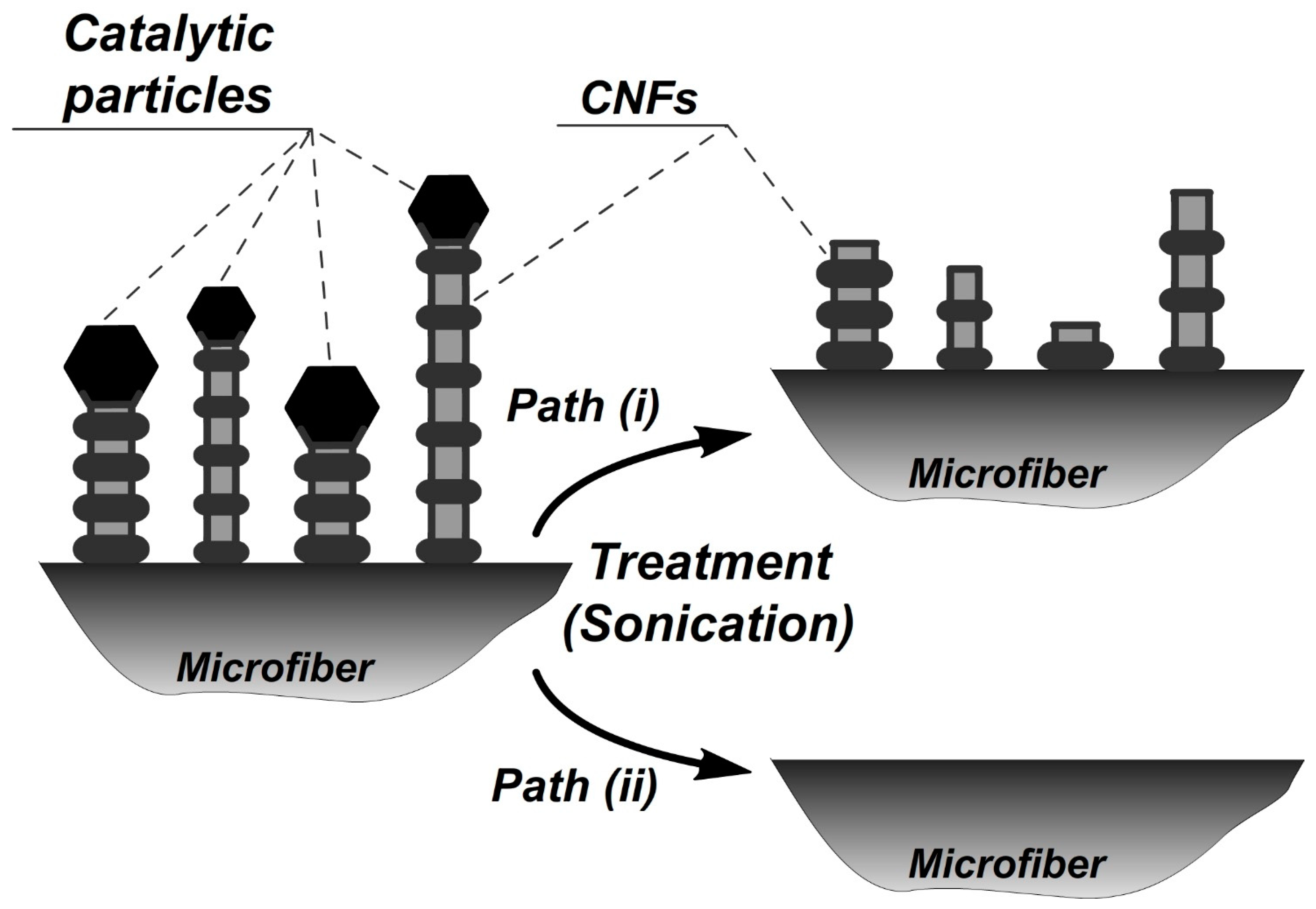
2.3.2. Methodology of “TEM-Sonication” Studies

Conventionally, after the preparation procedure, which is designed to preserve the native morphology of the studied material, the sample is visualized using TEM and then discarded. The proposed alternative algorithm implies the following procedures: after the first visualization, the sample is removed from the microscope, and then undergoes some kind of treatment (sonication, irradiation, chemical etching, etc.) before being visualized with TEM again. In the present study, the sonication procedure was chosen for the treatment of synthesized hierarchical materials. Such a cycle can be repeated more than once (Figure 1). It provides not only a normal TEM visualization of the samples, but also makes it possible to compare the adhesion strength between microfibers and CNF for a few samples (up to four at a time) simultaneously. Thus, the samples first visualized intact are then treated under the same conditions and visualized once again, thus allowing one to reveal the differences in the impact of the sonication on various hierarchical materials.
In order to provide the simultaneous treatment of a few TEM grids under identical conditions, a special metal holder was designed (Figure 2b). When it is dipped into the water precisely above the center of the sonic bath, all the samples are placed at the same distance from the center of the bottom (source of ultrasonic waves) and thus sonicated at the same conditions. To avoid the effects of possible asymmetry, the holder can be rotated during the sonication procedure. The sonication intensity is adjusted by the distance between the bottom of the bath and the holder (Figure 2c). After the sonication, the treated samples (TEM grids with glued microfibers, Figure 2a) were dried out and examined with the TEM method once again.
Note that in the case of conventional procedure used for visualization of damages or other surface changes, intact and treated samples are prepared independently using different TEM grids. Contrarily, the developed method provides an opportunity to visualize the same area of the microfiber’s surface with precision up to a single nanofiber before and after the treatment, thus revealing the fine structural aspects of the damage and comparing the behavior of all the samples under study.

2.3.3. Examination of the Adhesion Strength between Microfibers and CNF

An oriented monolayer of modified carbon or mineral microfibers was fixed on the surface of a copper TEM grid (75 mesh, SPI, Structure Probe, Inc., West Chester, PA, USA) by cyanoacrylate gel adhesive (on the edge). When the adhesive has dried, the surplus microfibers were cut off from the grid’s edge by a sharp blade and the grid was blown with compressed air to remove unattached fibers (Figure 2a). Then, the grid was examined by TEM.
After the TEM examination, four grids with different samples of CNF-coated microfibers were installed into a custom metal holder (Figure 2b) and then put into a sonic bath (Sapphire, Moscow, Russia) of 0.5 L in volume working at 35 kHz and 50 W. The holder was fixed above the center of the bath (Figure 2c). Thus, all the grids were exposed to the sonication treatment under the same conditions.
Before the sonication treatment, the grids were put into water, then dried and examined by TEM. This step is important to separate sonication and possible wetting–drying effects. It has been shown that the wetting-drying procedure does not have any noticeable influence on the CNF layer coating the surface of microfibers.
After 1 min of sonication, the grids were dried, and then each grid was placed into the TEM holder at the same orientation for examination of the same parts of the microfibers’ surface, which were visualized before the sonication procedure. The experiment was repeated for different sonication times.

2.3.4. TEM Visualization

The visualization procedure was carried out on a JEM 1400 (JEOL Ltd., Tokyo, Japan) transmission electron microscope working at 120-kV accelerating voltage. The TEM grids had special orientation marks for installation in a TEM holder at the same position. At low magnifications, up to five different microfibers were presented in the view area. At higher magnification, the microfiber–CNF interface was examined.

3. Results and Discussion

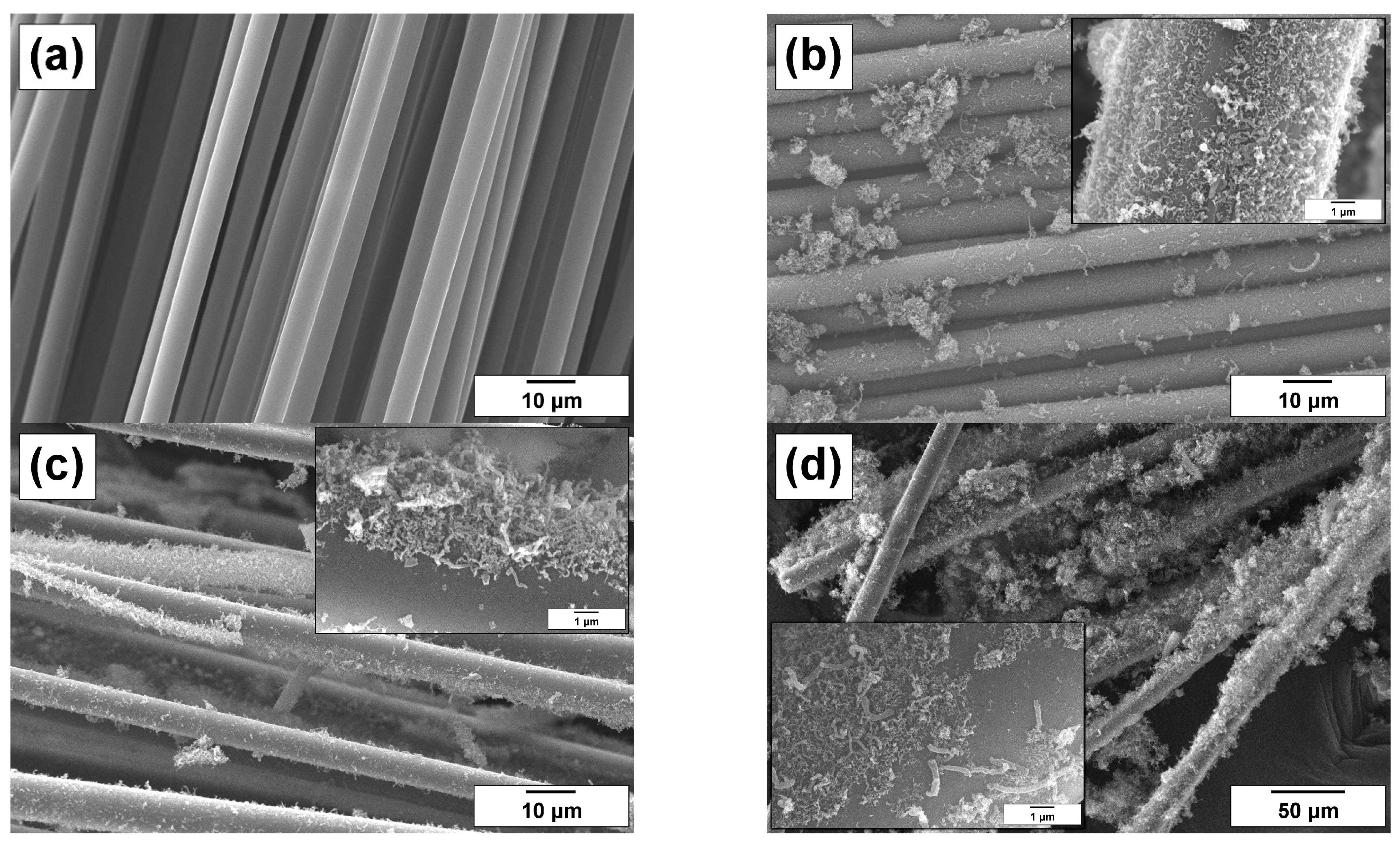
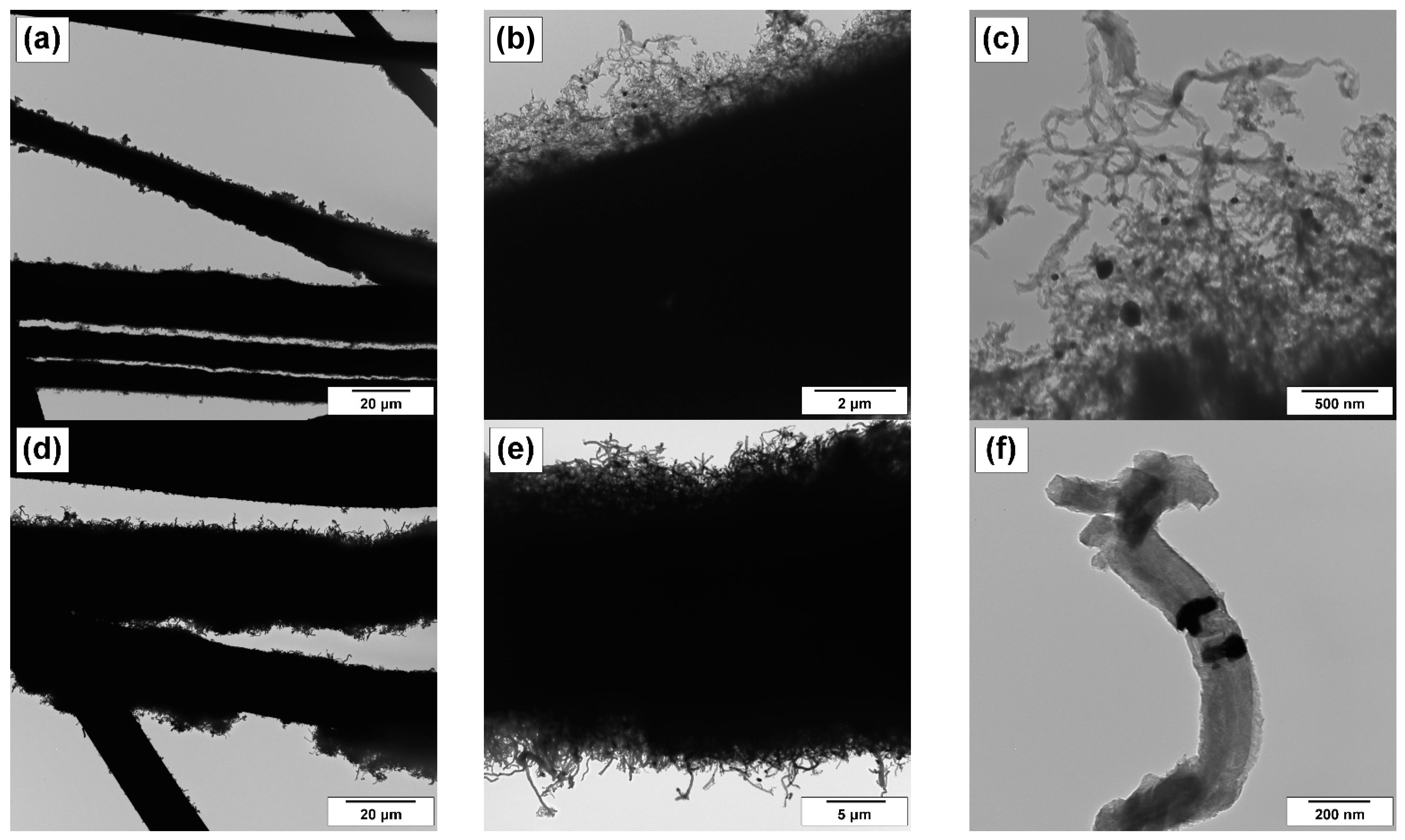
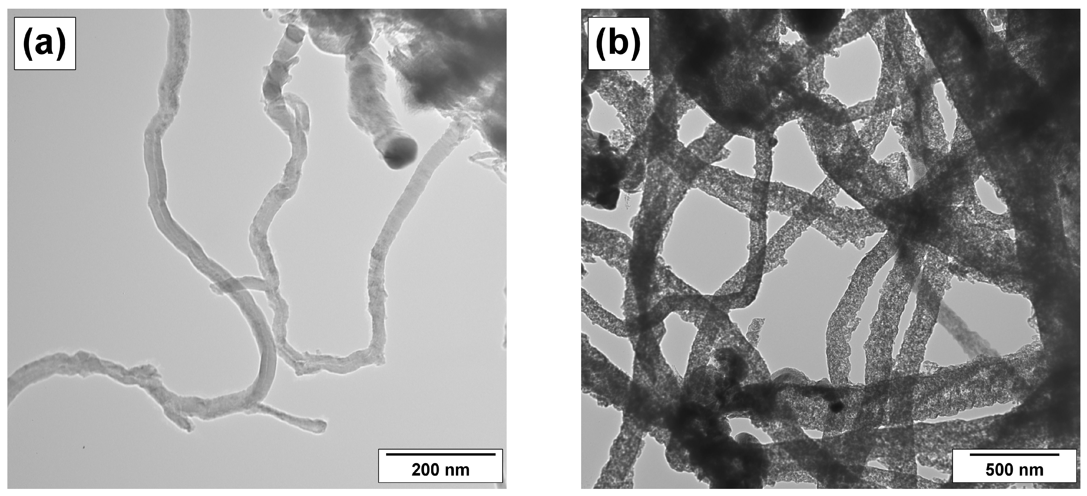
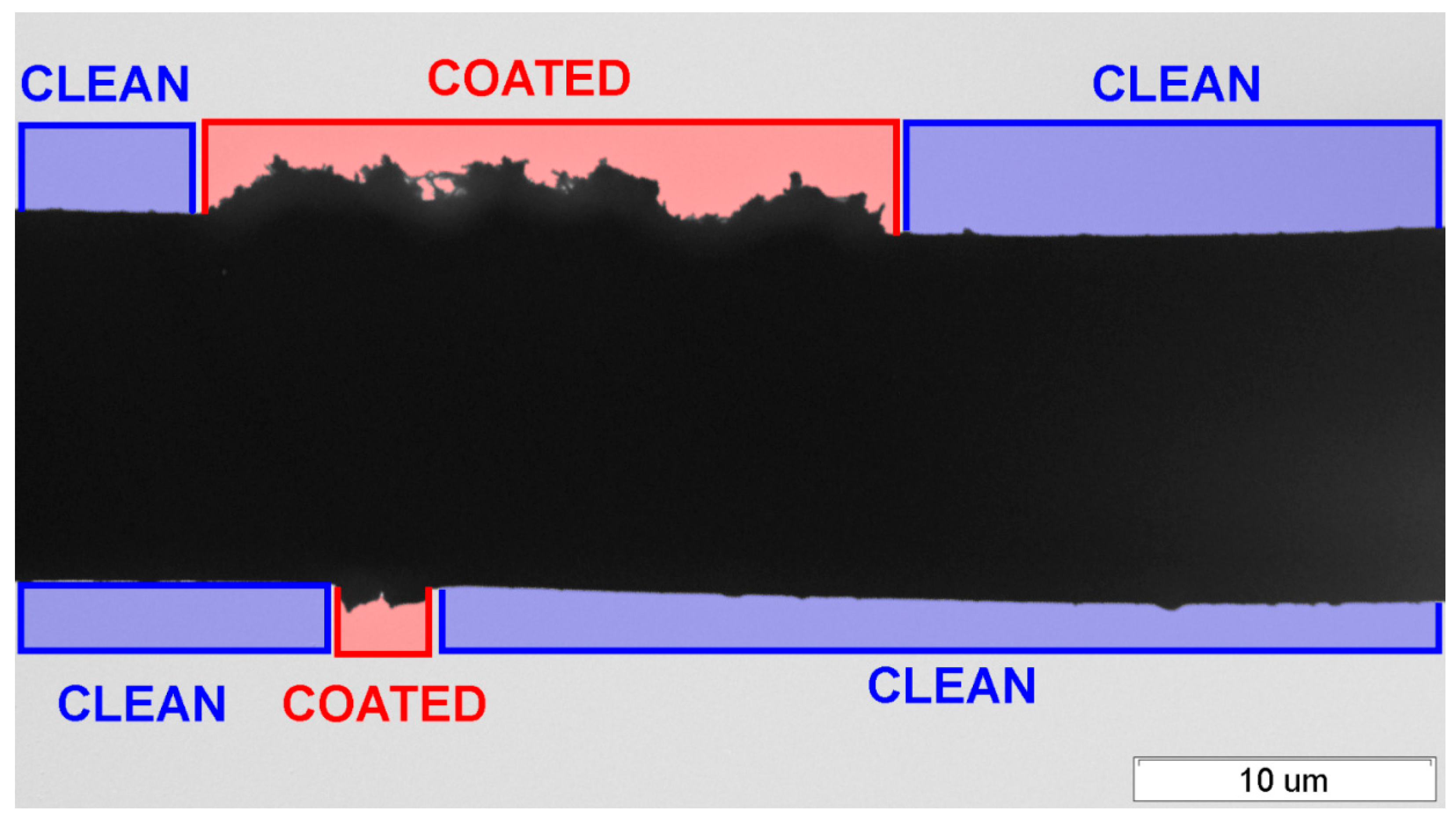
3.1. Examination of Hierarchical Materials by SEM and TEM Techniques

As shown from Figure 3a, the pristine sample of carbon microfibers (CMF) is composed of fibers of very close diameter (~7 μm), which are characterized by a rather smooth, non-defective surface. Other studied fibrous materials (basalt microfibers, fiberglass cloth) also possessed a similarly smooth surface before they were coated with CNF. The SEM images of the samples obtained via the catalytic growth of carbon nanofibers over the surface of microfibers are presented in Figure 3b–d. The surface of modified microfibers is seen to be covered by a nanostructured layer of CNF. The CNF mass fraction of 35–50 wt% was found to be sufficient to provide CNF-coating throughout all microfibrous samples.
In order to explore the structure of the produced hierarchical materials in more detail, the more powerful TEM technique was used. In this research, the sample preparation method allowing one to fix the specimen of hierarchical material over the TEM copper grid has been proposed. The selected TEM images for the CNF/CMF (YC = 40 wt%) and CNF/BMF (YC = 50 wt%) samples are presented in Figure 4. The general views shown in Figure 4a,d indicate that all the microfibers are more or less coated with the CNF layer. The individual microfibers covered with the dense “forest” of carbon nanofibers can be seen in Figure 4b,e. At last, the higher magnification (Figure 4c,f) makes it possible to discern the carbon nanostructured filaments themselves as well as to observe the metallic nickel particles embedded into the structure of CNFs. The observed nickel crystals are responsible for the catalytic growth of carbon nanofibers, which is known to occur in accordance with the carbide cycle mechanism [31].
It is worth noting that the nature of the carbon precursor used in catalytic decomposition (C2H4 or C2H4Cl2) affects noticeably the structural peculiarities of the grown carbon nanofibers. Figure 5 illustrates such an effect. It is seen that carbon filaments produced from ethylene (Figure 5a) are thinner in diameter and better packed if compared with those obtained from 1,2-DCE (Figure 5b). The presence of chlorine species in the reaction medium is known to be the key factor determining the formation of disordered carbon nanofibers with loose packing of graphene layers [29,32]. It might be expected that such “fluffy” filaments would be more fragile when subjected to further sonication or mechanical impact.

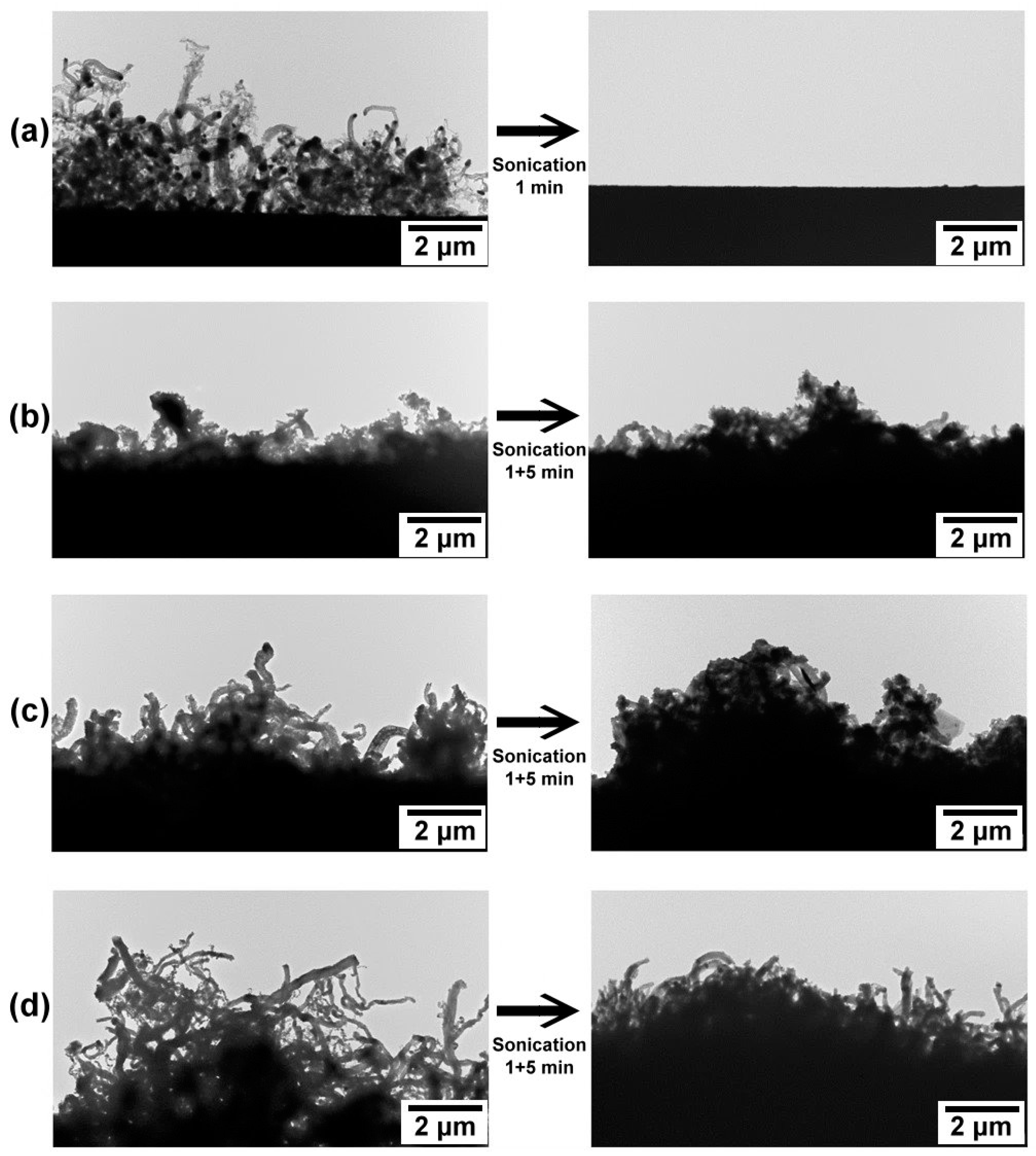
3.2. Examination of the Adhesion Strength in Hierarchical Materials by TEM Technique Coupled with the Sonication Treatment

The four obtained samples of hierarchical materials (see Table 1) were attached to the TEM grids and examined with TEM. Then, the grids were simultaneously sonicated at the same conditions (35 kHz, 50 W, 3 cm from the bottom of the sonic bath) for 1 min, dried at room temperature, and then examined with TEM again. In the next treatment experiment, the samples were sonicated for 5 min. The effect of the ultrasonic treatment is clearly seen in the TEM images (Figure 6). Moreover, it is possible to distinguish different effects of sonication on the surface of the CNF-modified microfibers, such as breakage of CNF and their detachment from the surface of the microfibers. These effects are schematically illustrated in Figure 7.
Thus, TEM examination of the sonicated samples (Figure 4) showed that the adhesion strength of the CNF layer is maximal for carbon-carbon system CNF/CMF, since only minor CNF damages after 5 min of sonication were observed. This characteristic is lower for basalt-carbon system CNF/BMF (breakage of CNF without full detachment of the layer) and particularly for fiberglass-carbon material CNF/FGC (full detachment of the CNF layer after just 1 min of sonication).
There is an example of using a sonication procedure for the examination of the adhesion strength between micro- and nanofibers in hierarchical materials in the literature [14]. Unlike that study, in the present research, TEM was used instead of SEM, and the experiments were conducted at a single-fiber level. The same microfibers were examined before and after the ultrasound treatment. In general, TEM provides more detailed imaging (Figure 5) than SEM, revealing the internal structure of nanofibers and the interfacial area. The thickness of the sample is critically important in TEM. Usually, this parameter should be approximately 100 nm. To meet this condition, typical protocols suggest removing CNF from the microfibers and depositing them on standard TEM grids [15]. In the developed method, carbon nanofibers were not detached from the microfibers. This allowed examining their distribution on the microfibers’ surface as well as the interfacial area at TEM resolution (Figure 5). Thus, the performed studies have shown that the relative adhesion strength for CNF-coated microfibers decreases in the following order: CNF/CMF > CNF/BMF > CNF/FGC.
In order to study the CNF-coated CMF more precisely, the distance between the source in the ultrasonic bath and the holder was minimized as much as possible. Then, the CNF–microfiber interface (a place where carbon nanofiber contacts with the surface of the carbon microfiber) was studied by a high-resolution TEM method. The detailed examination of this area (Figure 8) revealed that the surface of the graphitized carbon microfibers is coherent with the structure of the CNF fragments grown over it. This allows considering the epitaxial growth of carbon nanostructures on the graphitic surface of CMF. Therefore, the observed maximum adhesion strength of CNF on the CMF surface is defined by the high affinity of graphite-like structures.
It is important to note that the detachment of CNF from the microfiber’s surface can be inhomogeneous. To characterize this effect numerically, a simple semi-quantitative analysis of the low magnification images can be used (Figure 9). By assuming symmetry, it is possible to estimate semi-quantitatively the ratio of clean and coated areas of the microfiber. By measuring the lengths of “clean” (Lcl) and “coated” (Lco) areas of the microfibers, it is possible to calculate a coating coefficient using the following Equation (1):
k c = L c o L c l + L c o
If the measured length is equal for different samples, which were treated under the same conditions, this coefficient can be used for the quantitative comparison of their adhesion strength. For instance, the calculated values of the coating coefficient are compared in Table 2. To exclude the contribution of pre-existed heterogeneity in the surface of the hierarchical material, the same microfibers should be examined with TEM before and after the ultrasonic treatment.
The developed technique of sample preparation can be used not only for TEM studies as presented in this paper. It is applicable for other kinds of microscopic examinations (SEM, optical, etc.) as well. Moreover, the sonication procedure can be joined or replaced with some other treatments (irradiation, heating, mechanical stress, etc.) more suitable for the specific case.

4. Conclusions

The present paper aimed to study the peculiarities of carbon and mineral microfibers coated with carbon nanofibers. Such modification changes the surface properties of microfibers and enhances their interaction with various matrices. In order to study precisely the samples of hierarchical materials and estimate the strength of the interaction between microfibers and CNF, an original advanced approach based on the TEM technique has been developed. The proposed method of sample preparation for sequential TEM visualization considers an ultrasonic treatment of up to four samples simultaneously under the same conditions by using a specially designed sample holder. This technique can be applied for the quantitative estimation of the adhesion strength between CNF and the microfiber surface in such hierarchical materials. The performed study showed that the relative strength of carbon nanofibers coating the surface of microfibers decreases in a row: CNF/CMF > CNF/BMF > CNF/FGC. In the case of CNF/CMF material, the graphitized surface of carbon microfiber is coherent with the structure of carbon nanofiber fragments grown on it, which explains the highest adhesion strength of the carbon nanolayer coated on carbon microfibers.

Author Contributions

Conceptualization, D.V.K., I.V.K. and I.V.M.; methodology, D.V.K.; validation, I.V.M., S.D.A. and A.A.V.; formal analysis, D.V.K. and I.V.M.; investigation, D.V.K. and I.V.K.; resources, I.V.M.; data curation, I.V.K. and S.D.A.; writing—original draft preparation, D.V.K., I.V.M. and S.D.A.; writing—review and editing, I.V.M. and A.A.V.; visualization, D.V.K., S.D.A. and A.A.V.; project administration, I.V.M.; funding acquisition, I.V.M. All authors have read and agreed to the published version of the manuscript.

Funding

This work was supported by the Ministry of Science and Higher Education of the Russian Federation within the governmental order for the Boreskov Institute of Catalysis (project No. AAAA-A21-121011390054-1).

Institutional Review Board Statement

Not applicable.

Informed Consent Statement

Not applicable.

Data Availability Statement

Data are contained within the article.

Acknowledgments

SEM characterization of the samples was performed using the equipment of the Center of Collective Use “National Center of Catalysts Research”.

Conflicts of Interest

The authors declare no conflict of interest. The funders had no role in the design of the study; in the collection, analyses, or interpretation of data; in the writing of the manuscript; or in the decision to publish the results.

References

  1. Zhang, Z.; Cai, S.; Li, Y.; Wang, Z.; Long, Y.; Yu, T.; Shen, Y. High performances of plant fiber reinforced composites—A new insight from hierarchical microstructures. Compos. Sci. Technol. 2020, 194, 108151. [Google Scholar] [CrossRef]
  2. Valorosi, F.; De Meo, E.; Blanco-Varela, T.; Martorana, B.; Veca, A.; Pugno, N.; Kinloch, I.A.; Anagnostopoulos, G.; Galiotis, C.; Bertocchi, F. Graphene and related materials in hierarchical fiber composites: Production techniques and key industrial benefits. Compos. Sci. Technol. 2020, 185, 107848. [Google Scholar] [CrossRef]
  3. Karger-Kocsis, J.; Mahmood, H.; Pegoretti, A. All-carbon multi-scale and hierarchical fibers and related structural composites: A review. Compos. Sci. Technol. 2020, 186, 107932. [Google Scholar] [CrossRef]
  4. Farina, I.; Goodall, R.; Hernández-Nava, E.; di Filippo, A.; Colangelo, F.; Fraternali, F. Design, microstructure and mechanical characterization of Ti6Al4V reinforcing elements for cement composites with fractal architecture. Mater. Des. 2019, 172, 107758. [Google Scholar] [CrossRef]
  5. Li, Y.; Yi, X.; Yu, T.; Xian, G. An overview of structural-functional-integrated composites based on the hierarchical microstructures of plant fibers. Adv. Compos. Hybrid Mater. 2018, 1, 231–246. [Google Scholar] [CrossRef]
  6. Nepal, D.; Kang, S.; Adstedt, K.M.; Kanhaiya, K.; Bockstaller, M.R.; Brinson, L.C.; Buehler, M.J.; Coveney, P.V.; Dayal, K.; El-Awady, J.A. Hierarchically structured bioinspired nanocomposites. Nat. Mater. 2022, 22, 18–35. [Google Scholar] [CrossRef]
  7. Hagnell, M.K.; Åkermo, M. The economic and mechanical potential of closed loop material usage and recycling of fibre-reinforced composite materials. J. Clean. Prod. 2019, 223, 957–968. [Google Scholar] [CrossRef]
  8. Kerber, M.L.; Vinogradov, V.M.; Golovkin, G.S.; Gorbatkina, Y.A.; Kryzhanovskii, V.K.; Kuperman, A.M.; Simonov-Emel’yanov, I.D.; Khaliulin, V.I.; Bunakov, V.A. Polymeric Composite Materials: Structure, Properties, and Technology: A Textbook; Profession: St. Petersburg, Russia, 2008. (In Russian) [Google Scholar]
  9. Ponomareva, E.; Shkinev, V.; Zaglyadova, S.; Krasnikova, I.; Egorova, E. Copper Catalysts based on carbon–carbon fibrous materials for ethanol dehydrogenation. Russ. J. Appl. Chem. 2016, 89, 598–602. [Google Scholar] [CrossRef]
  10. Ponomareva, E.A.; Krasnikova, I.V.; Egorova, E.V.; Mishakov, I.V.; Vedyagin, A.A. Ethanol dehydrogenation over copper supported on carbon macrofibers. Mendeleev Commun. 2017, 27, 210–212. [Google Scholar] [CrossRef]
  11. Ponomareva, E.A.; Krasnikova, I.V.; Egorova, E.V.; Mishakov, I.V.; Vedyagin, A.A. Dehydrogenation of ethanol over carbon-supported Cu–Co catalysts modified by catalytic chemical vapor deposition. React. Kinet. Mech. Catal. 2017, 122, 399–408. [Google Scholar] [CrossRef]
  12. Petukhova, E.S.; Krasnikova, I.V. The effect of surface nanostructuring on the behavior of a fiber-reinforced polyethylene composite. AIP Conf. Proc. 2016, 1785, 030021. [Google Scholar] [CrossRef] [Green Version]
  13. Rahaman, A.; Kar, K.K. Carbon nanomaterials grown on E-glass fibers and their application in composite. Compos. Sci. Technol. 2014, 101, 1–10. [Google Scholar] [CrossRef]
  14. He, X.; Wang, C.; Tong, L.; Wang, R.; Cao, A.; Peng, Q.; Moody, S.; Li, Y. Direct measurement of grafting strength between an individual carbon nanotube and a carbon fiber. Carbon 2012, 50, 3782–3788. [Google Scholar] [CrossRef]
  15. Cooper, C.A.; Cohen, S.R.; Barber, A.H.; Wagner, H.D. Detachment of nanotubes from a polymer matrix. Appl. Phys. Lett. 2002, 81, 3873–3875. [Google Scholar] [CrossRef]
  16. Barber, A.H.; Cohen, S.R.; Wagner, H.D. Measurement of carbon nanotube–polymer interfacial strength. Appl. Phys. Lett. 2003, 82, 4140–4142. [Google Scholar] [CrossRef] [Green Version]
  17. Strus, M.C.; Cano, C.I.; Pipes, R.B.; Nguyen, C.V.; Raman, A. Interfacial energy between carbon nanotubes and polymers measured from nanoscale peel tests in the atomic force microscope. Compos. Sci. Technol. 2009, 69, 1580–1586. [Google Scholar] [CrossRef] [Green Version]
  18. Chen, L.; Yu, Z.; Yin, D.; Cao, K. Preparation and anticorrosion properties of BTA@HNTs-GO nanocomposite smart coatings. Compos. Interfaces 2020, 28, 1–16. [Google Scholar] [CrossRef]
  19. Xu, W.; Lan, R.; Du, D.; Humphreys, J.; Walker, M.; Wu, Z.; Wang, H.; Tao, S. Directly growing hierarchical nickel-copper hydroxide nanowires on carbon fibre cloth for efficient electrooxidation of ammonia. Appl. Catal. B-Environ. 2017, 218, 470–479. [Google Scholar] [CrossRef]
  20. Ji, D.; Peng, S.; Safanama, D.; Yu, H.; Li, L.; Yang, G.; Qin, X.; Srinivasan, M.; Adams, S.; Ramakrishna, S. Design of 3-dimensional hierarchical architectures of carbon and highly active transition metals (Fe, Co, Ni) as bifunctional oxygen catalysts for hybrid lithium–air batteries. Chem. Mater. 2017, 29, 1665–1675. [Google Scholar] [CrossRef]
  21. Krasnikova, I.V.; Mishakov, I.V.; Vedyagin, A.A.; Bauman, Y.I.; Korneev, D.V. Surface modification of microfibrous materials with nanostructured carbon. Mater. Chem. Phys. 2017, 186, 220–227. [Google Scholar] [CrossRef]
  22. Beaumont, P.W.R.; Soutis, C.; Hodzic, A. The Structural Integrity of Carbon Fiber Composites: Fifty Years of Progress and Achievement of the Science, Development, and Applications; Springer International Publishing: Cham, Switzerland, 2016. [Google Scholar]
  23. Qian, H.; Bismarck, A.; Greenhalgh, E.S.; Kalinka, G.; Shaffer, M.S.P. Hierarchical composites reinforced with carbon nanotube grafted fibers: The potential assessed at the single fiber level. Chem. Mater. 2008, 20, 1862–1869. [Google Scholar] [CrossRef]
  24. Taheri, M.L.; Stach, E.A.; Arslan, I.; Crozier, P.A.; Kabius, B.C.; LaGrange, T.; Minor, A.M.; Takeda, S.; Tanase, M.; Wagner, J.B. Current status and future directions for in situ transmission electron microscopy. Ultramicroscopy 2016, 170, 86–95. [Google Scholar] [CrossRef] [PubMed] [Green Version]
  25. Flannigan, D.J.; Zewail, A.H. 4D electron microscopy: Principles and applications. Acc. Chem. Res. 2012, 45, 1828–1839. [Google Scholar] [CrossRef]
  26. Ayache, J.; Beaunier, L.; Boumendil, J.; Ehret, G.; Laub, D. Sample Preparation Handbook for Transmission Electron Microscopy: Techniques; Springer Science & Business Media: Cham, Switzerland, 2010; Volume 2. [Google Scholar]
  27. Rao, D.S.; Muraleedharan, K.; Humphreys, C. TEM specimen preparation techniques. Microsc. Sci. Technol. Appl. Educ. 2010, 2, 1232. [Google Scholar]
  28. Bauman, Y.I.; Mishakov, I.V.; Buyanov, R.A.; Vedyagin, A.A.; Volodin, A.M. Catalytic properties of massive iron-subgroup metals in dichloroethane decomposition into carbon products. Kinet. Catal. 2011, 52, 547–554. [Google Scholar] [CrossRef]
  29. Mishakov, I.V.; Vedyagin, A.A.; Bauman, Y.I.; Shubin, Y.V.; Buyanov, R.A. Synthesis of Carbon Nanofibers via Catalytic Chemical Vapor Deposition of Halogenated Hydrocarbons. In Carbon Nanofibers: Synthesis, Applications and Performance; Chang-Seop, L., Ed.; Nova Science Publishers: Hauppauge, NY, USA, 2018; pp. 77–181. [Google Scholar]
  30. Tokareva, I.V.; Mishakov, I.V.; Korneev, D.V.; Vedyagin, A.A.; Golokhvast, K.S. Nanostructuring of the carbon macrofiber surface. Nanotechnol. Russ. 2015, 10, 158–164. [Google Scholar] [CrossRef]
  31. Chesnokov, V.V.; Buyanov, R.A. The formation of carbon filaments upon decomposition of hydrocarbons catalysed by iron subgroup metals and their alloys. Russ. Chem. Rev. 2000, 69, 623–638. [Google Scholar] [CrossRef]
  32. Mishakov, I.V.; Chesnokov, V.V.; Buyanov, R.A.; Chuvilin, A.L. Morphology and structure of carbon resulting from decomposition of chlorohydrocarbons on nickel and cobalt containing catalysts. Reac. Kinet. Catal. Lett. 2002, 76, 361–367. [Google Scholar] [CrossRef]
Figure 1. Procedure chart illustrating an approach used to examine the adhesion strength of CNF on the surface of microfibers.
Coatings 13 00256 g001
Figure 2. Schematic representation of the procedures used for the preparation and treatment of the hierarchical samples: (a) attachment of the microfibers to a TEM grid; (b) assembling a holder for simultaneous treatment of four TEM grids (every slot has a notch to remove the grid using sharp tweezers (marked with the arrows), scale bar 10 mm); (c) sonication treatment of the holder (the distance from the bottom (h) can be varied to adjust the intensity of the treatment).
Coatings 13 00256 g002
Figure 3. SEM images of the samples: (a) pristine carbon microfibers (CMF); (b) CNF/CMF (YC = 40 wt%); (c) CNF/FGC (YC = 36 wt%); (d) CNF/BMF (YC = 50 wt%).
Coatings 13 00256 g003
Figure 4. TEM images of the pristine hierarchical samples: (ac) CNF/CMF (YC = 40 wt%); (df) CNF/BMF (YC = 50 wt%). Active particles of metallic Ni catalyzing the growth of CNF are seen in TEM images (c,f).
Coatings 13 00256 g004
Figure 5. Effect of carbon precursor on the structure of CNFs: (a) CNF/CMF; (b) CNF/CMF(DCE).
Coatings 13 00256 g005
Figure 6. TEM images of the surface of modified microfibers before and after sonication treatment procedure: (a) CNF/FGC; (b), (c) CNF/CMF; (d) CNF/BMF. Note that the same areas of the fiber’s surface are compared.
Coatings 13 00256 g006
Figure 7. Schematic illustration of different sonication effects, which can be distinguished by means of TEM visualization: path (i)—breakage of CNFs; path (ii)—detachment of CNF from the microfiber surface.
Coatings 13 00256 g007
Figure 8. HR TEM image of the CNF-coated CMF sample.
Coatings 13 00256 g008
Figure 9. TEM image (low magnification) of the CNF/BMF hierarchical material sample after 5 min of sonication.
Coatings 13 00256 g009
Table 1. Designation of the hierarchical samples and the conditions of their synthesis. Note that all samples were preliminarily reduced in hydrogen prior to contact with the corresponding reaction mixture.
#Sample DesignationType of MicrofiberCharacteristics * of MicrofiberCoating ConditionsCarbon Yield (YC), wt%
d,
μm
L,
mm
WH2O,
mL/g
1CNF/CMFChopped carbon microfiber (CMF)5–65–70.90600 °C
C2H4
30 min
40
2CNF/CMF(DCE)600 °C
C2H4Cl2 **
30 min
50
3CNF/BMFChopped basalt microfiber (BMF)2090.30500 °C
C2H4 ***
15 min
50
4CNF/FGC(DCE)Fiberglass cloth (FGC)10100.36600 °C
C2H4Cl2 **
120 min
36
(*) d is the average diameter of one filament; L is the length of the fiber; WH2O is water capacity. (**) The reaction gas-phase composition is C2H4Cl2/H2/Ar = 7/37/56 (vol%). (***) The reaction gas-phase composition is C2H4/Ar = 33/67 (vol%).
Table 2. The coating coefficient (kc) values calculated from TEM images for the hierarchical materials studied in the present work.
Sonication Time, minCNF/CMFCNF/BMFCNF/FGC
10.750.740.2
50.560.230
Disclaimer/Publisher’s Note: The statements, opinions and data contained in all publications are solely those of the individual author(s) and contributor(s) and not of MDPI and/or the editor(s). MDPI and/or the editor(s) disclaim responsibility for any injury to people or property resulting from any ideas, methods, instructions or products referred to in the content.

