
Bi-Phase NiCo2S4-NiS2/CFP Nanocomposites as a Highly Active Catalyst for Oxygen Evolution Reaction

College of Materials, Xiamen University, Xiamen 361005, China
*
Authors to whom correspondence should be addressed.
Coatings 2023, 13(2), 313; https://doi.org/10.3390/coatings13020313
Submission received: 6 December 2022
/
Revised: 18 January 2023
/
Accepted: 20 January 2023
/
Published: 31 January 2023
(This article belongs to the Collection Feature Papers of Coatings for Energy Applications)
Abstract
:Pursuing oxygen evolution reaction (OER) catalysts with high activity and stability is attracting many researchers. Here, we first designed and synthesized a biphasic three-dimensional structured catalyst of nickel–cobalt sulfide NiCo2S4-NiS2/CFP, which is a nickel–cobalt sulfide composite decorated on carbon fiber paper (CFP) by a one-step hydrothermal method. It exhibited an overpotential of about 165 mV at a current density of 10 mA cm−2 and a small Tafel slope of 81.54 mV dec−1. Furthermore, the long-term stability of the NiCo2S4-NiS2/CFP nanocomposite was 90.0% of the initial current density even after 12 h. The excellent catalytic performance of the NiCo2S4-NiS2/CFP nanocomposite can be attributed to several aspects. Firstly, the petal-like morphology of the NiCo2S4-NiS2 nanocomposite exposes more active sites. Secondly, the stability of the composite catalyst is significantly enhanced by its firm anchoring on the CFP. Thirdly, the catalytic performance was significantly improved by the addition of mixed valence of Ni or Co on the {111} plane of spinel NiCo2S4. Finally, the three-dimensional CFP substrate provides an efficient pathway and a stable integrated structure for the transmission of electrons and ions. Our one-step hydrothermal synthesis method provides a simple and economical way to obtain high-performance and robust OER catalysts.
1. Introduction
With today’s society facing a severe fossil fuel energy crisis and environmental pollution, clean and sustainable energy sources are becoming a necessity for a highly civilized modern human society [1]. Therefore, searching for and developing new renewable energy sources is an urgent task at the moment [2,3,4]. The hydrogen energy which could be produced by water splitting [5,6] attracted the attention of many researchers because it is clean and inexpensive. However, owing to the kinetic sluggishness which results from four protons coupled with four-electron transfer in acidic and basic media, the efficiency of water splitting is greatly hindered by the half reaction oxygen evolution reaction (OER) [7,8,9]. RuO2 and IrO2 as the typical precious metal oxide catalysts are indicated as the state-of-the-art and best electrocatalysts for the OER, but the large-scale applications of those catalysts were blocked by their rareness and expensiveness [10,11]. Therefore, it is highly urgent and imperative to develop new and cheap electrocatalysts for OER with good electrochemical performance [12]. There are several ways to reduce the cost and improve the performance of catalysts, such as using metal doping [13], designing heterostructures [14] or deriving them from MOFs [15], which have been widely explored.
Recently, transition metal sulfides, which are abundant in the Earth’s crust, have been widely investigated as potential OER catalysts due to their good electrical conductivity and high electrochemical activity [16,17,18]. However, some disadvantages of transition metal sulfides still limit their practical applications, such as scarce catalytic active sites, poor electron transport, low electrolyte contact efficiency and poor stability [19]. Many researchers have found that octahedral spinel structures contain more active sites than other structures, and thus are more likely to exhibit efficient catalytic activity [20,21,22]. It is well known that NiCo2S4, a typical material with octahedral spinel structure, always has good catalytic properties [23,24]. A number of researchers have reported single-phase NiCo2S4 [25,26,27], but bi-phase NiCo2S4 catalysts are rarely mentioned.
Herein, a bi-phase NiCo2S4-NiS2 decorated on the surface of carbon fiber paper (CFP) was synthesized via a simple one-step hydrothermal method, and the as-synthesized nanocomposites were used as the catalysts for OER. Based on the high conductivity of electron/ion, larger specific surface areas, plentiful transfer channels of mass and excellent mechanical strength [28], CFP not only worked as an excellent conductive substrate but also provided a support 3D structure for catalyst anchoring [29]. The active material is grown directly on the CFP to form a self-supporting catalyst, which avoids the loss of active sites and the decrease in electron/ion transportation with additional binder of Nafion solution and additives [30,31]. A one-step hydrothermal synthesis method of catalysts is more efficient and cost effective [16,32]. As a conclusion, the electrocatalytic performance would be improved with the exposure of more active sites which could be realized on the NiCo2S4-NiS2/CFP catalyst. Here, the as-prepared NiCo2S4-NiS2/CFP catalyst indicated a lower overpotential of 165 mV with a current density of 10 mA cm−2 for OER, a small Tafel slope of 81.54 mV dec−1 and a long-term stability of about 90.0% of its initial current density after 12 h.
2. Experimental Section
2.1. Reagents
All chemicals used in experiments were analytical reagents without further treatments. CFP was purchased from Dongli (Tianjin, China) Investment Co., Ltd. Cobalt nitrate hexahydrate (Co(NO3)2·6H2O), nickel acetate tetrahydrate (Ni(CH3COO)2·4H2O), potassium hydroxide, nitric acid and thiourea were bought from Xilong Science Co., Ltd. (Chengdu, China) Anhydrous ethanol, IrO2 powder and hydrochloric acid were bought from China Pharmaceutical Group Chemical Reagents Co., Ltd. (Shanghai, China) The dispersant sodium dodecyl sulfate (SDS) was supplied by Shantou Dahao Fine Chemicals Co., Ltd.
2.2. Treatment of CFP
First, a piece of CFP was cut into pieces with an area of 1.0 × 1.0 cm2. Second, the CFP sheets were immersed in aqua regia solution (8 mL 65% HNO3 mixed with 24 mL 37% HCl) and kept in a fume hood at room temperature for 6 h [26] to get rid of metals which remained on the surface of the CFP, to form a functionalized and hydrophilic surface. Finally, processed CFP sheets were washed with distilled water thoroughly to obtain oxidized carbon fiber paper (OCFP).
2.3. Synthesis of NiCo2S4-NiS2/CFP, Ni3S4-NiS2/CFP and Co2S/CFP
All samples were synthesized by a hydrothermal method as follows and Ni3S4-NiS2/CFP and Co2S/CFP were also prepared in the same way as a reference group. Firstly, all solutions were prepared as shown for each solution listed in Table 1. Then, the solutions were transferred into a 100 mL Teflon-lined stainless-steel autoclave after being vigorously stirred for about half an hour, respectively. The autoclaves were kept at 220 °C for 12 h. After the autoclaves cooled to room temperature, the residues were collected with centrifugation and washed by anhydrous ethanol and deionized water three times, respectively. These three samples were dried in a vacuum desiccator at 80 °C for 12 h and denoted as NiCo2S4-NiS2/CFP, Ni3S4-NiS2/CFP and Co2S/CFP. The average mass loading of NiCo2S4-NiS2/CFP, Ni3S4-NiS2/CFP and Co2S/CFP on substrates was 0.81 mg cm−2, 0.75 mg cm−2 and 0.73 mg cm−2, respectively.
2.4. Physical Characterization
The morphologies and compositions of samples were characterized by a field emission scanning electron microscope (FESEM, Hitachi SU-70, 10kV, Japan) equipped with an energy dispersive spectrometer (EDS, 20kV) analyzer. X-ray diffraction (XRD, Bruker, Germany) was implemented on a Bruker-AxsD8 X-ray diffractometer with a 2θ range from 10° to 90°. Rietveld refinement was accomplished by GSAS software. Transmission electron microscopy (TEM, Philips-FEI, Eindhoven, The Netherlands), high-resolution transmission electron microscopy (HRTEM), high-angle annular dark-field scanning transmission electron microscopy (HAADF-STEM) and corresponding energy dispersive spectroscopic (EDS) mapping analyses were all performed using a Talos F200s at 200 KV. X-ray photoelectron spectroscopy (XPS, USA) data were collected by using a PHI Quantum 2000 Scanning ESCA Microprobe with an Al X-ray source. The Raman measurement was performed in the XploRA microprobe Raman system (HORIBA, Kyoto, Japan).
2.5. Electrochemical Testing
All the electrochemical measurements were tested by employing an Autolab 302N in an electrochemistry workstation (Metrohm Autolab B.V., Utrecht, The Netherlands) at room temperature. The obtained CFP, NiCo2S4-NiS2/CFP, Ni3S4-NiS2/CFP and Co2S/CFP were all cut into 0.5 × 1 cm2 pieces and employed as working electrodes directly. The IrO2 working electrode was prepared with the follow steps. Firstly, 5 mg IrO2 powder was dispersed into 1 mL solution (anhydrous ethanol/5 wt.% Nafion, 19:1, v/v). Then, the solution was ultrasonicated for more than 30 min to obtain a homogeneous solution. Finally, 20 μL of the homogeneous solution was dropped onto the surface of glassy carbon (diameter is 5 mm) to obtain the working electrode (the catalyst loading was ~0.51 mg/cm2). A mercuric oxide electrode and platinum (Pt) net were used as a reference electrode and counter electrode, respectively. The electrolyte was 1.0 M KOH (pH = 14). All measured potentials were calibrated with a reversible hydrogen electrode (RHE). The ultimate potential was calculated by the following equation: E (vs. RHE) = E (vs. Hg/HgO) + 0.098 V + 0.059 V·pH. Linear sweep voltammetry (LSV) was manipulated at a scan rate 5 mV/s, ranging from 1.0 V to 2.0 V (vs. RHE). Cyclic voltammetry (CV) tests were carried out with a scan rate of 10 mV/s, 20 mV/s, 40 mV/s, 60 mV/s, 80 mV/s and 100 mV/s, respectively, in the range of 1.0–1.1 V (vs. RHE). The working electrodes were scanned several times for CV measurements at a scan rate 5 mV/s, ranging from 1.0 V to 2.0 V (vs. RHE) until the curves were steady for LSV and CV testing. Electrochemical impedance spectra (EIS) were conducted at open circuit voltage (OCP, shown on the screen of the system) vs. RHE with 5 mV AC amplitude and frequency ranging from 0.1 Hz to 100 kHz. The stability of as-prepared catalysts was assessed with a chronoamperometry test.
3. Results and Discussion
3.1. Synthesis and Characterization
During the hydrothermal reaction, oxidized OCFP was reduced to CFP again because of using the reducing reagent thiourea, thus NiCo2S4-NiS2 particles were decorated and anchored on the surface of CFP after the hydrothermal reaction at 220 °C to form the NiCo2S4-NiS2/CFP nanocomposites (Figure S1). The simple synthetic process is illustrated as a schematic diagram in Figure 1.
Figure 2 displays the morphology of the substrate and synthesized catalyst. Original commercial CFP was constituted by crossed microfibers with a diameter of approximately 7 μm and covered with carbon layers (Figure 2a), and a comparatively clear texture of the CFP can be found in Figure S2a,b. After being immersed in aqua regia for 6 h, CFP was oxidized into OCFP. It was detected that the surface of substrates had become smoother which means that metal impurities in CFP had been cleaned up without damaging the surface texture (Figure S2c,d). Petaloid-like NiCo2S4-NiS2 with a diameter from 1 to 3 μm was formed by the aggregated NiCo2S4-NiS2 nanowires, which were decorated and anchored on the surface of the CFP microfibers, as shown in Figure 2b,c. It can be found that the petaloid-like NiCo2S4-NiS2 was distributed on the surface of the 3D skeleton of CFP uniformly, which makes the nanocomposites have a large specific surface and rough surface. The large specific surface, rough surface and the strong interaction may result in a good electrocatalytic performance of the as-synthesized NiCo2S4-NiS2/CFP [33]. The morphologies of Ni3S4-NiS2/CFP and CoS2/CFP are shown in Figure S3a,b, respectively. The whole outline is the same as the sample of the NiCo2S4-NiS2/CFP which is shown in Figure 2b. In Figure S3a,b, it can be seen that all Ni3S4-NiS2 particles and CoS2 particles are anchored on the surface of the CFP microfibers uniformly.
The Rietveld refinement of XRD patterns of NiCo2S4-NiS2 is shown in Figure 3. It suggests that the as-prepared electrocatalyst is composed of NiCo2S4 (JCPDS 20-0782) with a spinel structure (Fd-3m) and NiS2 (JCPDS 73-0574). According to JCPDS 20-0782, the diffraction peak at 16.341° can be ascribed to the (111) plane of the NiCo2S4, which belongs to the {111} plane family of the spinel structure. Knözinger and Ratnasamy et al. [20,34] reported that the exposed octahedral cations in the {111} plane family of the spinel are more coordinated, resulting in better active catalytic performance. Furthermore, the weight percentages of NiCo2S4 phase and NiS2 phase in the as-prepared catalyst are 87.34 wt% and 12.66 wt%, which were calculated by Rietveld structure refinement with GSAS software [35], as shown in Figure 3. The mole rate of NiCo2S4 phase and NiS2 phase is 2.78:1, which means the spinel NiCo2S4 phase has a dominant position in the bi-phase NiCo2S4-NiS2.
The TEM image in Figure 4a shows that the petaloid-like NiCo2S4-NiS2 is composed of many nanowires. The HRTEM image in the inset of Figure 4a shows that the petaloid-like NiCo2S4-NiS2 nanocomposite is closely interlaced with NiCo2S4 and NiS2, and these small particles are interlaced and stacked to form distinct lattice dislocations. The planar spacing of NiCo2S4 is 0.542 nm, which corresponds to the (111) lattice plane. The adjacent planar spacing is 0.328 nm which is attributed to the NiS2 (1–11) lattice plane. From the selected area electron diffraction (SAED) image of Figure 4b, the polycrystalline electron diffraction rings of NiCo2S4-NiS2 could be traced to the planes of NiCo2S4 (JCPDS 20-0782) and NiS2 (JCPDS 73-0574), which agree with the XRD pattern of NiCo2S4-NiS2 in Figure 3. As can be seen in Figure 4c–f, the EDS patterns show the presence of uniform dispersion of Ni, Co and S in the petal-like NiCo2S4-NiS2 nanocomposites. The XRD patterns of Ni3S4-NiS2 and CoS2 are displayed in Figure S4a,b, and it can be seen that the Ni3S4-NiS2 is composed of Ni3S4 (JCPDS 76-1813) and NiS2 (JCPDS 88-1709). The HRTEM, SAED and the corresponding EDX elemental mapping of Ni3S4-NiS2 and CoS2 are shown in Figures S5 and S6, respectively.
To further demonstrate that the NiCo2S4-NiS2 particles were successfully immobilized on CFP, Raman spectroscopy was used to examine the NiCo2S4-NiS2/CFP nanocomposites. The spectrum is shown in Figure S7, in which the strong peak which was located at around 1350 cm−1 corresponds to the D band, which implies a disorder or defect site of the sp2 carbon atoms. Meanwhile, the other peak at around 1590 cm−1 can be attributed to the graphitic characteristic peak of the G band [36,37]. At the same time, the intensity of the D band/the intensity of the G band (ID/IG) indicates the degree of defects in carbon-based materials. ID/IG values of CFP, OCFP and NiCo2S4-NiS2/CFP are 0.247, 0.105 and 0.657, respectively. To maintain energy stability, NiCo2S4-NiS2 nanoparticles prefer to anchor and assemble on the defect sites of CFP, which further leads to the increase in defects in NiCo2S4-NiS2/CFP nanocomposites. All these consequences proved that the NiCo2S4-NiS2 nanocomposites had been successfully anchored on CFP and self-assembled as flower petals to expose many active sites. Moreover, the small peak detected at around 1620 cm−1 (the red rectangle in Figure S7) in the CFP and NiCo2S4-NiS2/CFP demonstrated OCFP was reduced to CFP during the hydrothermal reaction.
3.2. Electrocatalytic Testing
All the electrocatalytic performances of NiCo2S4-NiS2/CFP nanocomposites were tested in 1M KOH solution. The NiCo2S4-NiS2/CFP sample was used as a working electrode directly. The LSV curves are shown in Figure 5a, in which the NiCo2S4-NiS2/CFP nanocomposites have the lowest overpotential of 165 mV at the current density of 10 mA cm−2 in 1M KOH, compared to the Ni3S4-NiS2/CFP nanocomposites (255 mV), the CoS2/CFP nanocomposites (323 mV) and the commercial IrO2 (368 mV). Electrocatalysis performance of NiCo2S4-NiS2/CFP nanocomposites in this work is better than in other reported works which can be seen in Table S1. The OER activity of pure CFP was also tested for contrast, and a poor performance is revealed in Figure 5a. These results indicated that the high OER activity can be attributed to the transition metal sulfides. The large specific surface and rough surface provided by the petaloid spherules of NiCo2S4-NiS2 nanocomposites have improved the electrocatalytic performance of the NiCo2S4-NiS2/CFP. Compared with monometallic (Ni or Co) sulfide, the catalytic performance of the NiCo2S4-NiS2/CFP nanocomposites could be improved by the synergistic effect of Ni and Co ions. Compared with Ni3S4-NiS2/CFP, the catalytic performance of NiCo2S4-NiS2/CFP could be boosted greatly with the existing spinel structure of NiCo2S4.
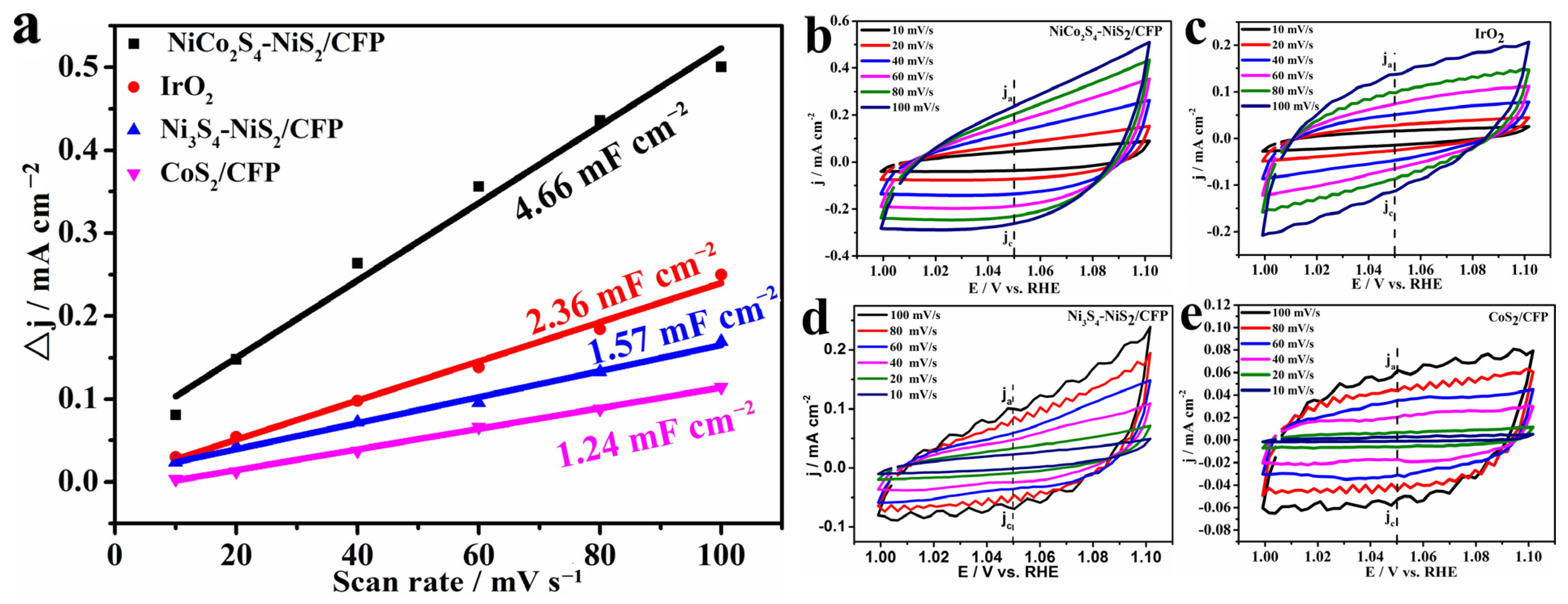
To study the catalytic kinetics of NiCo2S4-NiS2/CFP, the Tafel slopes of all samples were determined from the LSV curves. According to the Tafel equation: η = b log j + c, where η is the potential (V vs. RHE), j is the current density (mA cm−2), c is the constant, b is the Tafel slope. The Tafel slope b is an important parameter to understand the kinetic mechanism of OER, a smaller b means faster kinetics of OER. In Figure 5b, the NiCo2S4-NiS2/CFP shows a Tafel slope of about 81.54 mV dec−1, which is lower than for the CFP (211 mV dec−1), Ni3S4-NiS2/CFP (179 mV dec−1) and CoS2/CFP (218.35 mV dec−1), with a value even lower than the noble-metal oxide IrO2 (134.75 mV dec−1). The ECSAs were estimated from CDL measurements using CV scans at different scan rates (Figure S8). Results showed that NiCo2S4-NiS2/CFP possessed the biggest double-layer capacitance of 4.66 mF cm−2 which is consistent with the large surface area of the petaloid-like morphology in SEM images. The Nyquist plots of electrocatalysts were obtained for the OER half-cell at open circuit voltage vs. RHE with 5 mV AC amplitude and the results are shown in Figure 5c. The semi-circle represents the charge transfer resistance (Rct) of electrocatalysts. It shows that Rct of NiCo2S4-NiS2/CFP is smaller than that of CFP, Ni3S4-NiS2/CFP, CoS2/CFP and IrO2. The lower charge transfer resistance would prompt better electrocatalytic performance. The faster kinetic process of NiCo2S4-NiS2/CFP can be attributed to the abundant proton transfer channels of CFP [28] and the mixed ions of Ni2+, Co2+ and Co3+ in the NiCo2S4-NiS2/CFP nanocomposites (Figure 6a,b).
Stability is an indispensable criterion for practical OER performance, so the long-term durability of the NiCo2S4-NiS2/CFP sample was tested by chronoamperometric measurements at a constant potential of 1.4 V vs. RHE. As shown in Figure 5d, the NiCo2S4-NiS2/CFP nanocomposite retains an excellent durability of about 90.0% of the initial current density over a 12 h test. This can also be confirmed by the inset graphic in Figure 5d, showing the overpotential just increased a little bit after a 12 h durability test. Figure S9 reflects the morphology of NiCo2S4-NiS2/CFP after a 12 h durability test, and the overall petaloid morphology is almost the same except the surface became smoother, resulting from NiCo2S4-NiS2 nanocomposites strongly anchored on CFP to form a strong binding between NiCo2S4-NiS2 and CFP.
To further confirm the composition changes in as-prepared NiCo2S4-NiS2/CFP before and after a 12 h durability test, XPS measurement was employed. Figure 6a,d show the Ni 2p spectra of NiCo2S4-NiS2/CFP before and after a 12 h durability test, and it can be seen that the outlines of two Ni 2p are almost the same. The peaks located at 855 eV, 873.3 eV and 873.6 eV all correspond to the Ni2+, the peaks located at 861.5 eV and 879.6 eV are labeled as the shake-up satellite peak [38,39] in Figure 6a,d. The peak located at 855.9 eV in Figure 6d is labeled as Ni3+, which means some Ni2+ was oxidized to Ni3+ after the 12 h durability test. The Co 2p spectra before and after the 12 h durability test are displayed in Figure 6b,e, in which the peaks at 778.5 eV and 795.5 eV are ascribed to Co3+ and the peaks at 780.5 eV and 797.2 eV are ascribed to Co2+ [24,40], meaning that Co ions appeared with mixed valence in the spinel structure NiCo2S4 of Ni3S4-NiS2/CFP. Meanwhile, the peaks at 803 eV and 784.5 eV are ascribed to two satellite peaks [41]. Compared with Figure 6b, the peak located at 778.5 eV (see Figure 6e) disappeared, which means some Co3+ was reduced to Co2+ after the 12 h durability test. It is assumed that the excellent stability can be attributed to the spinel-structured Co3+ [17], and the 10% decrease in current density over the 12 h test could be ascribed to the reduction of Co3+ in NiCo2S4. A distinct change in S is observed in Figure 6c,f. Before the 12 h durability test, the peaks situated at 163.7 eV and 161.4 eV could be attributed to the characteristic peak of metal sulfide bonds and S2− with low coordination, respectively [42,43]. The peak situated at 162.6 eV is attributed to bridging S22− [44], which suggests that non-saturated S atoms existed in the Ni–S areas in the NiS2 phase, and it is assumed that the presence of bridging S22− may facilitate the protons’ reduction and accelerate the electron transportation in the process of OER [17]. The peak situated at 167.4 eV is a satellite peak [45]. After the 12 h durability test, only a S2− peak located at 163.7 eV and a satellite peak at 168.9 eV could be detected, as the peaks of S2− and S22− situated at 161.4 eV and 162.6 eV (see Figure 6c) disappeared. Those results revealed that S22− and some S2− were oxidized into hydroxide within the OER process [46]. This could be confirmed with the O XPS spectra and the EDS results of the catalyst before and after the 12 h durability test (see Figures S10 and S11). In Figure S10, the oxygen vacancy peaks disappear after the 12 h durability test, the peaks at 530.4 eV and 531.5 eV could be attributed to the hydroxyl-metal (Co-OH, Ni-OH) and the peak at 532.2 eV could be attributed to adsorbed oxygen [46,47]. The changes in the S and O atoms are revealed by Figure S11, in which the decrease in S and increase in O indicate that part of the S22− and S2− had been oxidized to form the hydroxyl, which also corroborates the XPS results.
Compared with Ni 2p spectrum of Ni3S4-NiS2/CFP shown in Figure S12a and Co 2p spectrum of CoS2/CFP shown in Figure S13a, the mixed valences of Ni2+, Co2+ and Co3+ existed in the catalyst NiCo2S4-NiS2/CFP nanocomposites. The mixed metal valences can provide donor–acceptor chemisorption sites during the reversible adsorption of oxygen and then achieve relatively high electronic conductivity through valence electron hopping between cations [24,48].
The electrochemically effective surface area (ECSA) is also another parameter to evaluate the OER catalytic performance. It originated from double-layer capacitance (Cdl) on the catalyst surface, which satisfies the following equation: ECSA = Cdl/Cs [49,50], while the value of CS in 1 M KOH is 0.04 mF cm−2. Cdl was calculated by cyclic voltammetry (CV) measured at scan rates from 10 to 100 mV/s. To obtain the currents related only to double-layer capacitance, scan rate-dependent CV was measured between 1.00 and 1.10 V (vs. RHE), where the redox processes do not occur (as shown in Figure 7). The △j = ja − jc, ja and jc were taken at 1.05 V vs. RHE. From the fitted linear slope, we calculated the Cdl which is half of the slope [51]. Figure 7a reflects that the fitted linear slope values ranked from high to low are NiCo2S4-NiS2/CFP > IrO2 > Ni3S4-NiS2/CFP > CoS2/CFP. This result suggested that the ECSA of the as-prepared catalyst NiCo2S4-NiS2/CFP is larger than that of the single metal (Ni and Co) sulfides and IrO2, and the catalyst with larger ECSA could produce more ion-accessible sites and exhibit better electrocatalytic activity.
4. Conclusions
Here, petaloid-structured bi-phase bimetal sulfide catalyst NiCo2S4-NiS2/CFP nanocomposites were synthesized by a simple hydrothermal method successfully. Compared with the monometallic (Ni or Co) sulfide with CFP, NiCo2S4-NiS2/CFP exhibits remarkable performance with a low overpotential of 165 mV at a current density of 10 mA cm−2 in alkaline solution, and also a detectable Tafel slope of 81.54 mV dec−1. Under similar conditions, the overpotential of the synthesized NiCo2S4-NiS2/CFP is lower than that of most recently reported electrocatalysts for OER. Meanwhile, a retention rate of 90.0% could be obtained when the catalyst was tested for 12 h. The superior performance of the as-prepared NiCo2S4-NiS2/CFP nanocomposites benefits from several factors, including the special petaloid morphology and 3D structure provided by the CFP substrate, the strong coupling effect between spinel NiCo2S4 and NiS2, the mixed valence of Ni and Co and the exposed active sites on the {111} plane. Furthermore, this work offers a simple and economical way via a hydrothermal method to obtain efficient and robust spinel NiCo2S4 base catalysts for OER.
Supplementary Materials
The following supporting information can be downloaded at: https://www.mdpi.com/article/10.3390/coatings13020313/s1, Figure S1. The surface change after as prepared NiCo2S4-NiS2 anchored on the surface of CFP; Figure S2. Low-magnification SEM images of (a) CFP and (c) OCFP. High-magnification SEM images of (b) CFP and (d) OCFP; Figure S3. The morphologies of (a) Ni3S4-NiS2/CFP and (b) CoS2/CFP; Figure S4. XRD patterns of (a)Ni3S4-NiS2 and (b) CoS2; Figure S5. (a,b) HRTEM image of Ni3S4-NiS2. (c,d) Selected area electron diffraction (SAED) diffraction ring of Ni3S4-NiS2. (e,f) The area chosen to do EDX elemental mapping and the corresponding EDX elemental mapping images for Ni and S respectively; Figure S6. (a) The TEM image of CoS2. (b) HRTEM image of CoS2. (c,d) Selected area electron diffraction (SAED) diffraction ring of CoS2. (e,f) The area chosen to do EDX elemental mapping nd the corresponding EDX elemental mapping images for Co and S respectively; Figure S7. Raman spectra of CFP, OCFP and NiCo2S4-NiS2/CFP; Figure S8. Double-layer capacitances (a) and CV scans at different scan rates (b–e); Figure S9. The morphology of NiCo2S4-NiS2/CFP after 12 h durability test; Figure S10. The O XPS spectra of as-prepared catalyst before (a) and after (b)12 h durability test; Figure S11. The EDS results of NiCo2S4-NiS2/CFP (a) before 12 h durability test. (b) After 12 h durability test; Figure S12. The XPS spectra of (a) Ni 2p, (b) S 2p in Ni3S4-NiS2/CFP; Figure S13. The XPS spectra of (a) Co 2p, (b) S 2p in CoS2/CFP; Table S1. Comparison of OER activity of NiCo2S4-NiS2/CFP with that of most reported nick-el-cobalt sulfide catalysts tested in alkaline solution [52,53,54,55,56,57,58].
Author Contributions
Conceptualization, writing—review and editing, J.L.; methodology, Y.X., X.L., and T.M.; formal analysis, Y.X., Z.W. and Z.H.; supervision and funding acquisition, G.Y. All authors have read and agreed to the published version of the manuscript.
Funding
This research was funded by the National Natural Science Foundation of China (Grant No. 51971184), the Natural Science Foundation of Fujian Province of China (No. 2021J01043).
Institutional Review Board Statement
Not applicable.
Informed Consent Statement
Not applicable.
Data Availability Statement
Not applicable.
Conflicts of Interest
The authors declare have no conflict of interest.
References
- Yang, T.L.; Xia, Y.J.; Mao, T.L.; Ding, Q.W.; Wang, Z.J.; Hong, Z.Y.; Han, J.J.; Peng, D.L.; Yue, G.H. Phosphorus Vacancies and Heterojunction Interface as Effective Lithium-Peroxide Promoter for Long-Cycle Life Lithium–Oxygen Batteries. Adv. Funct. Mater. 2022, 32, 2209876. [Google Scholar] [CrossRef]
- Dutta, S.; Indra, A.; Feng, Y.; Han, H.; Song, T. Promoting electrocatalytic overall water splitting with nanohybrid of transition metal nitride-oxynitride. Appl. Catal. B Environ. 2019, 241, 521–527. [Google Scholar] [CrossRef]
- Hu, C.; Dai, L. Multifunctional Carbon-Based Metal-Free Electrocatalysts for Simultaneous Oxygen Reduction, Oxygen Evolution, and Hydrogen Evolution. Adv. Mater. 2017, 29, 1604942. [Google Scholar] [CrossRef]
- Sathiskumar, C.; Ramakrishnan, S.; Vinothkannan, M.; Karthikeyan, S.; Yoo, D.J.; Kim, A.R. Nitrogen-Doped Porous Carbon Derived from Biomass Used as Trifunctional Electrocatalyst toward Oxygen Reduction, Oxygen Evolution and Hydrogen Evolution Reactions. Nanomaterials 2019, 10, 76. [Google Scholar] [CrossRef] [PubMed] [Green Version]
- Hu, C.G.; Chen, X.Y.; Dai, Q.B.; Wang, M.; Qu, L.T.; Dai, L.M. Earth-Abundant Carbon Catalysts for Renewable Generation of Clean Energy from Sunlight and Water. Nano Energy 2017, 41, 367–376. [Google Scholar] [CrossRef]
- Xia, G.; Li, D.; Chen, X.; Tan, Y.; Tang, Z.; Guo, Z.; Liu, H.; Liu, Z.; Yu, X. Carbon-Coated Li3 N Nanofibers for Advanced Hydrogen Storage. Adv. Mater. 2013, 25, 6238–6244. [Google Scholar] [CrossRef] [PubMed]
- Koper, M.T.M. Thermodynamic theory of multi-electron transfer reactions: Implications for electrocatalysis. J. Electroanal. Chem. 2011, 660, 254–260. [Google Scholar] [CrossRef]
- Jiao, Y.; Zheng, Y.; Jaroniec, M.; Qiao, S.Z. Design of Electrocatalysts for Oxygen- and Hydrogen-Involving Energy Conversion Reactions. Chem. Soc. Rev. 2015, 44, 2060–2086. [Google Scholar] [CrossRef]
- Zhao, H.H.; Yang, Y.; Dai, X.P.; Qiao, H.Y.; Yong, J.X.; Luan, X.B.; Yu, L.; Luan, C.L.; Wang, Y.; Zhang, X. Nico-Dh Nanodots Anchored on Amorphous Nico-Sulfide Sheets as Efficient Electrocatalysts for Oxygen Evolution Reaction. Electrochim. Acta 2019, 295, 1085–1092. [Google Scholar] [CrossRef]
- Zhu, Y.P.; Liu, Y.P.; Ren, T.Z.; Yuan, Z.Y. Self-Supported Cobalt Phosphide Mesoporous Nanorod Arrays: A Flexible and Bifunctional Electrode for Highly Active Electrocatalytic Water Reduction and Oxidation. Adv. Funct. Mater. 2015, 25, 7337–7347. [Google Scholar] [CrossRef]
- Xu, W.; Lu, Z.; Lei, X.; Li, Y.; Sun, X. A Hierarchical Ni-Co-O@Ni-Co-S Nanoarray as an Advanced Oxygen Evolution Reaction Electrode. Phys. Chem. Chem. Phys. 2014, 16, 20402–20405. [Google Scholar] [CrossRef] [PubMed]
- Wang, C.; Zhao, Y.; Liu, J.; Gong, P.; Li, X.; Zhao, Y.; Yue, G.; Zhou, Z. Highly Hierarchical Porous Structures Constructed from Nio Nanosheets Act as Li Ion and O(2) Pathways in Long Cycle Life, Rechargeable Li-O(2) Batteries. Chem. Commun. 2016, 52, 11772–11774. [Google Scholar] [CrossRef]
- Alburaih, H.A.; Ansari, M.Z.; Abid, A.G.; Khosa, R.Y.; Ashiq, M.N.; Manzoor, S.; Aman, S.; Chaudhry, H.; Waheed, M.S.; Taha, T.A. Study on active sites of Mn-doped iron selenide on pencil electrode for electrocatalytic water splitting. J. Sol-Gel Sci. Technol. 2022, 11, 1–9. [Google Scholar] [CrossRef]
- Khan, M.T.N.; Ahmed, F.; Houda, S.; Manzoor, S.; Hasnain, K.; Zahra, M.; Hussain, R.; Ansari, M.Z.; Hegazy, H.H.; Ashiq, M.N. Facile synthesis of novel Ag@cerium zirconate heterostructure for efficient oxygen evolution reaction. Surf. Interfaces 2022, 35, 102410–102420. [Google Scholar] [CrossRef]
- Owidah, Z.O.; Aman, S.; Abdullah, M.; Manzoor, S.; Fallatah, A.M.; Ibrahim, M.M.; Elnasr, T.A.S.; Ansari, M.Z. Metal oxide/carbon nanosheet arrays derivative of stacked metal organic frameworks for triggering oxygen evolution reaction. Ceram. Int. 2022, 49, 5936–5943. [Google Scholar] [CrossRef]
- Chen, H.; Jiang, J.; Zhang, L.; Wan, H.; Qi, T.; Xia, D. Highly conductive NiCo2S4 urchin-like nanostructures for high-rate pseudocapacitors. Nanoscale 2013, 5, 8879–8883. [Google Scholar] [CrossRef]
- Jing, F.; Lv, Q.Y.; Xiao, J.; Wang, Q.J.; Wang, S. Highly Active and Dual-Function Self-Supported Multiphase Nis-Nis2-Ni3s2/Nf Electrodes for Overall Water Splitting. J. Mater. Chem. A 2018, 6, 14207–14214. [Google Scholar] [CrossRef]
- Chinnadurai, D.; Manivelan, N.; Prabakar, K. Modulating the Intrinsic Electrocatalytic Activity of Copper Sulfide by Silver Doping for Electrocatalytic Overall Water Splitting. Chemelectrochem 2022, 9, e202200254. [Google Scholar] [CrossRef]
- Viswanathan, V.; Pickrahn, K.L.; Luntz, A.C.; Bent, S.F.; Norskov, J.K. Nanoscale Limitations in Metal Oxide Electrocatalysts for Oxygen Evolution. Nano Lett. 2014, 14, 5853–5857. [Google Scholar] [CrossRef] [PubMed] [Green Version]
- Chauhan, M.; Reddy, K.P.; Gopinath, C.S.; Deka, S. Copper Cobalt Sulfide Nanosheets Realizing a Promising Electrocatalytic Oxygen Evolution Reaction. ACS Catal. 2017, 7, 5871–5879. [Google Scholar] [CrossRef]
- Jacobs, J.P.; Maltha, A.; Reintjes, J.G.H.; Drimal, J.; Ponec, V.; Brongersma, H.H. The Surface of Catalytically Active Spinels. J. Catal. 1994, 147, 294–300. [Google Scholar] [CrossRef]
- Liu, Y.; Xiao, C.; Lyu, M.; Lin, Y.; Cai, W.; Huang, P.; Tong, W.; Zou, Y.; Xie, Y. Ultrathin Co3S4 Nanosheets that Synergistically Engineer Spin States and Exposed Polyhedra that Promote Water Oxidation under Neutral Conditions. Angew. Chem. Int. Ed. 2015, 54, 11231–11235. [Google Scholar] [CrossRef] [PubMed]
- Liu, D.; Lu, Q.; Luo, Y.; Sun, X.; Asiri, A.M. NiCo2S4 nanowires array as an efficient bifunctional electrocatalyst for full water splitting with superior activity. Nanoscale 2015, 7, 15122–15126. [Google Scholar] [CrossRef]
- Liu, Q.; Jin, J.; Zhang, J. NiCo2S4@Graphene as a Bifunctional Electrocatalyst for Oxygen Reduction and Evolution Reactions. ACS Appl. Mater. Interfaces 2013, 5, 5002–5008. [Google Scholar] [CrossRef]
- Li, F.; Xu, R.C.; Li, Y.M.; Liang, F.; Zhang, D.F.; Fu, W.F.; Lv, X.J. N-doped carbon coated NiCo2S4 hollow nanotube as bifunctional electrocatalyst for overall water splitting. Carbon 2019, 145, 521–528. [Google Scholar] [CrossRef]
- Feng, X.; Jiao, Q.; Cui, H.; Yin, M.; Li, Q.; Zhao, Y.; Li, H.; Zhou, W.; Feng, C. One-Pot Synthesis of NiCo2S4 Hollow Spheres via Sequential Ion-Exchange as an Enhanced Oxygen Bifunctional Electrocatalyst in Alkaline Solution. ACS Appl. Mater. Interfaces 2018, 10, 29521–29531. [Google Scholar] [CrossRef] [PubMed]
- Kang, Z.; Guo, H.J.; Wu, J.; Sun, X.; Zhang, Z.; Liao, Q.L.; Zhang, S.C.; Si, H.N.; Wu, P.W.; Wang, L.; et al. Engineering an Earth-Abundant Element-Based Bifunctional Electrocatalyst for Highly Efficient and Durable Overall Water Splitting. Adv. Funct. Mater. 2019, 29, 1807031. [Google Scholar] [CrossRef]
- Khan, Z.; Senthilkumar, B.; O Park, S.; Park, S.; Yang, J.; Lee, J.H.; Song, H.K.; Kim, Y.; Kwak, S.K.; Ko, H. Carambola-shaped VO2 nanostructures: A binder-free air electrode for an aqueous Na–air battery. J. Mater. Chem. A 2017, 5, 2037–2044. [Google Scholar] [CrossRef]
- Ma, T.T.; Dai, Z.; Shen, X.R.; Jiao, Q.Z.; Zhao, Y.; Li, H.S.; Feng, C.H. Three-Dimensional Porous MnCo2S4 Microrugby Balls Supported on Carbon Cloth for Efficient Oxygen Evolution Reaction. Chemelectrochem 2022, 9, e202200552. [Google Scholar] [CrossRef]
- Zhong, M.X.; Song, N.; Li, C.M.; Wang, C.; Chen, W.; Lu, X.F. Controllable Growth of Fe-Doped Nis2 on Nife-Carbon Nanofibers for Boosting Oxygen Evolution Reaction. J. Colloid Interface Sci. 2022, 614, 556–565. [Google Scholar] [CrossRef]
- Zhou, X.C.; Yang, H.; Rao, D.W.; Yan, X.H. Morphology Controllable NiCo2S4 Nanostructure on Carbon Cloth for Enhanced Electrocatalytic Water Oxidation. J. Alloys Compd. 2022, 897, 163152. [Google Scholar] [CrossRef]
- Nguyen, V.H.; Shim, J.-J. In situ growth of hierarchical mesoporous NiCo2S4@MnO2 arrays on nickel foam for high-performance supercapacitors. Electrochim. Acta 2015, 166, 302–309. [Google Scholar] [CrossRef]
- Zhang, X.Q.; Zhao, Y.C.; Wang, C.G.; Li, X.; Liu, J.D.; Yue, G.H.; Zhou, Z.D. Facile synthesis of hollow urchin-like NiCo2O4 microspheres for high-performance sodium-ion batteries. J. Mater. Sci. 2016, 51, 9296–9305. [Google Scholar] [CrossRef]
- Knözinger, H.; Ratnasamy, P. Catalytic Aluminas: Surface Models and Characterization of Surface Sites. Catal. Rev. 1978, 17, 31–70. [Google Scholar] [CrossRef]
- Toby, B.H. Expgui, a Graphical User Interface for Gsas. J. Appl. Crystallogr. 2001, 34, 210–213. [Google Scholar] [CrossRef] [Green Version]
- Li, Z.Q.; Lu, C.J.; Xia, Z.P.; Zhou, Y.; Luo, Z. X-ray diffraction patterns of graphite and turbostratic carbon. Carbon 2007, 45, 1686–1695. [Google Scholar] [CrossRef]
- Pimenta, M.A.; Dresselhaus, G.; Dresselhaus, M.S.; Cançado, L.G.; Jorio, A.; Saito, R. Studying disorder in graphite-based systems by Raman spectroscopy. Phys. Chem. Chem. Phys. 2007, 9, 1276–1290. [Google Scholar] [CrossRef]
- Su, Y.Z.; Xiao, K.; Li, N.; Liu, Z.Q.; Qiao, S.Z. Amorphous Ni(OH)2 @ three-dimensional Ni core–shell nanostructures for high capacitance pseudocapacitors and asymmetric supercapacitors. J. Mater. Chem. A 2014, 2, 13845–13853. [Google Scholar] [CrossRef]
- Wu, Z.C.; Wang, X.; Huang, J.S.; Gao, F. A Co-doped Ni–Fe mixed oxide mesoporous nanosheet array with low overpotential and high stability towards overall water splitting. J. Mater. Chem. A 2018, 6, 167–178. [Google Scholar] [CrossRef]
- Shuai, C.; Mo, Z.L.; Niu, X.H.; Yang, X.; Liu, G.G.; Wang, J.; Liu, N.J.; Guo, R.B. Hierarchical NiCo2S4 nanosheets grown on graphene to catalyze the oxygen evolution reaction. J. Mater. Sci. 2020, 55, 1627–1636. [Google Scholar] [CrossRef]
- Wu, X.Y.; Li, S.M.; Wang, B.; Liu, J.H.; Yu, M. Graphene Foam Supported Multilevel Network-Like NiCo2S4 Nanoarchitectures for Robust Lithium Storage and Efficient Orr Catalysis. New J. Chem. 2017, 41, 115–125. [Google Scholar] [CrossRef]
- Yin, J.L.; Zhang, H.; Luo, J.Q.; Yao, M.Q.; Hu, W.C. High-boiling-point solvent synthesis of mesoporous NiCo2S4 with high specific surface area as supercapacitor electrode material. J. Mater. Sci. Mater. Electron. 2017, 28, 2093–2099. [Google Scholar] [CrossRef]
- Du, W.M.; Wang, Z.Y.; Zhu, Z.Q.; Hu, S.; Zhu, X.Y.; Shi, Y.F.; Pang, H.; Qian, X.F. Facile Synthesis and Superior Electrochemical Performances of Coni2s4/Graphene Nanocomposite Suitable for Supercapacitor Electrodes. J. Mater. Chem. A 2014, 2, 9613–9619. [Google Scholar] [CrossRef]
- Liu, N.; Guo, Y.; Yang, X.; Lin, H.; Yang, L.; Shi, Z.; Zhong, Z.; Wang, S.; Tang, Y.; Gao, Q. Microwave-Assisted Reactant-Protecting Strategy toward Efficient Mos2 Electrocatalysts in Hydrogen Evolution Reaction. ACS Appl. Mater. Interfaces 2015, 7, 23741–23749. [Google Scholar] [CrossRef]
- Jiang, J.Y.; Yan, C.Y.; Zhao, X.H.; Luo, H.X.; Xue, Z.M.; Mu, T.C. A PEGylated deep eutectic solvent for controllable solvothermal synthesis of porous NiCo2S4 for efficient oxygen evolution reaction. Green Chem. 2017, 19, 3023–3031. [Google Scholar] [CrossRef]
- Yuan, F.F.; Wei, J.D.; Qin, G.X.; Ni, Y.H. Carbon Cloth Supported Hierarchical Core-Shell NiCo2s4@Coni-Ldh Nanoarrays as Catalysts for Efficient Oxygen Evolution Reaction in Alkaline Solution. J. Alloys Compd. 2020, 830, 154658. [Google Scholar] [CrossRef]
- Liu, Y.; Bai, Y.; Han, Y.; Yu, Z.; Zhang, S.; Wang, G.; Wei, J.; Wu, Q.; Sun, K. Self-Supported Hierarchical Feconi-Lth/NiCo2O4/Cc Electrodes with Enhanced Bifunctional Performance for Efficient Overall Water Splitting. ACS Appl. Mater. Interfaces 2017, 9, 36917–36926. [Google Scholar] [CrossRef]
- Hamdani, M.; Singh, R.N.; Chartier, P. Co3o4 and Co- Based Spinel Oxides Bifunctional Oxygen Electrodes. Int. J. Electrochem. Sci. 2010, 5, 556–577. [Google Scholar]
- McCrory, C.C.; Jung, S.; Peters, J.C.; Jaramillo, T.F. Benchmarking Heterogeneous Electrocatalysts for the Oxygen Evolution Reaction. J. Am. Chem. Soc. 2013, 135, 16977–16987. [Google Scholar] [CrossRef]
- Trasatti, S.; Petrii, O.A. Real Surface Area Measurements in Electrochemistry. J. Electroanal. Chem. 1992, 327, 353–376. [Google Scholar] [CrossRef]
- Zhan, T.R.; Liu, X.L.; Lu, S.S.; Hou, W.G. Nitrogen doped NiFe layered double hydroxide/reduced graphene oxide mesoporous nanosphere as an effective bifunctional electrocatalyst for oxygen reduction and evolution reactions. Appl. Catal. B Environ. 2017, 205, 551–558. [Google Scholar] [CrossRef]
- Darband, G.B.; Aliofkhazraei, M.; Hyun, S.; Rouhaghdam, A.S.; Shanmugam, S. Electrodeposition of Ni-Co-Fe mixed sulfide ultrathin nanosheets on Ni nanocones: A low-cost, durable and high performance catalyst for electrochemical water splitting. Nanoscale 2019, 11, 16621–16634. [Google Scholar] [CrossRef] [PubMed]
- Hong, Y.R.; Mhin, S.; Kim, K.M.; Han, W.S.; Choi, H.; Ali, G.; Chung, K.Y.; Lee, H.J.; Moon, S.I.; Dutta, S.; et al. Electrochemically activated cobalt nickel sulfide for an efficient oxygen evolution reaction: Partial amorphization and phase control. J. Mater. Chem. A 2019, 7, 3592–3602. [Google Scholar] [CrossRef]
- Zou, H.; He, B.; Kuang, P.; Yu, J.; Fan, K. Metal-Organic Framework-Derived Nickel-Cobalt Sulfide on Ultrathin Mxene Nanosheets for Electrocatalytic Oxygen Evolution. ACS Appl. Mater. Interfaces 2018, 10, 22311–22319. [Google Scholar] [CrossRef] [PubMed]
- Tang, Y.; Yang, H.; Sun, J.; Xia, M.; Guo, W.; Yu, L.; Yan, J.; Zheng, J.; Chang, L.; Gao, F. Phase-pure Pentlandite Ni4.3Co4.7S8 Binary Sulfide as Efficient Bifunctional Electrocatalyst for Oxygen Evolution and Hydrogen Evolution. Nanoscale 2018, 10, 10459–10466. [Google Scholar] [CrossRef] [PubMed]
- Qin, K.; Wang, L.; Wen, S.; Diao, L.; Liu, P.; Li, J.; Ma, L.; Shi, C.; Zhong, C.; Hu, W.; et al. Designed synthesis of NiCo-LDH and derived sulfide on heteroatom-doped edge-enriched 3D rivet graphene films for high-performance asymmetric supercapacitor and efficient OER. J. Mater. Chem. A 2018, 6, 8109–8119. [Google Scholar] [CrossRef]
- Zhao, C.; Li, P.; Shao, D.; Zhang, R.; Wang, S.; Zhu, Z.; Zhao, C. Phytic acid-derived Co2-xNixP2O7-C/RGO and its superior OER electrocatalytic performance. Int. J. Hydrog. Energy 2019, 44, 844–852. [Google Scholar] [CrossRef]
- Yu, Z.; Bai, Y.; Zhang, S.; Liu, Y.; Zhang, N.; Sun, K. MOF-directed templating synthesis of hollow nickel-cobalt sulfide with enhanced electrocatalytic activity for oxygen evolution. Int. J. Hydrog. Energy 2018, 43, 8815–8823. [Google Scholar] [CrossRef]
Figure 1.
Schematic diagram showing the process for synthesizing NiCo2S4-NiS2/CFP.

Figure 2.
Morphologies of NiCo2S4-NiS2/CFP. (a) SEM of CFP, (b,c) NiCo2S4-NiS2/CFP.

Figure 3.
Rietveld refinement of XRD patterns of NiCo2S4-NiS2.

Figure 4.
(a) The TEM image of NiCo2S4-NiS2, the inset is HRTEM image of NiCo2S4-NiS2. (b) Selected area electron diffraction (SAED) ring of NiCo2S4-NiS2. (c–f) The area chosen for EDX elemental mapping of Ni, Co and S, respectively.
Figure 4.
(a) The TEM image of NiCo2S4-NiS2, the inset is HRTEM image of NiCo2S4-NiS2. (b) Selected area electron diffraction (SAED) ring of NiCo2S4-NiS2. (c–f) The area chosen for EDX elemental mapping of Ni, Co and S, respectively.

Figure 5.
OER performance of NiCo2S4-NiS2/CFP. (a) LSV of CFP, NiCo2S4-NiS2/CFP, Ni3S4-NiS2/CFP, CoS2/CFP and commercial IrO2. (b) Tafel slopes acquired from LSV in (a). (c) Nyquist plots of EIS. (d) The durability of NiCo2S4-NiS2/CFP.
Figure 5.
OER performance of NiCo2S4-NiS2/CFP. (a) LSV of CFP, NiCo2S4-NiS2/CFP, Ni3S4-NiS2/CFP, CoS2/CFP and commercial IrO2. (b) Tafel slopes acquired from LSV in (a). (c) Nyquist plots of EIS. (d) The durability of NiCo2S4-NiS2/CFP.
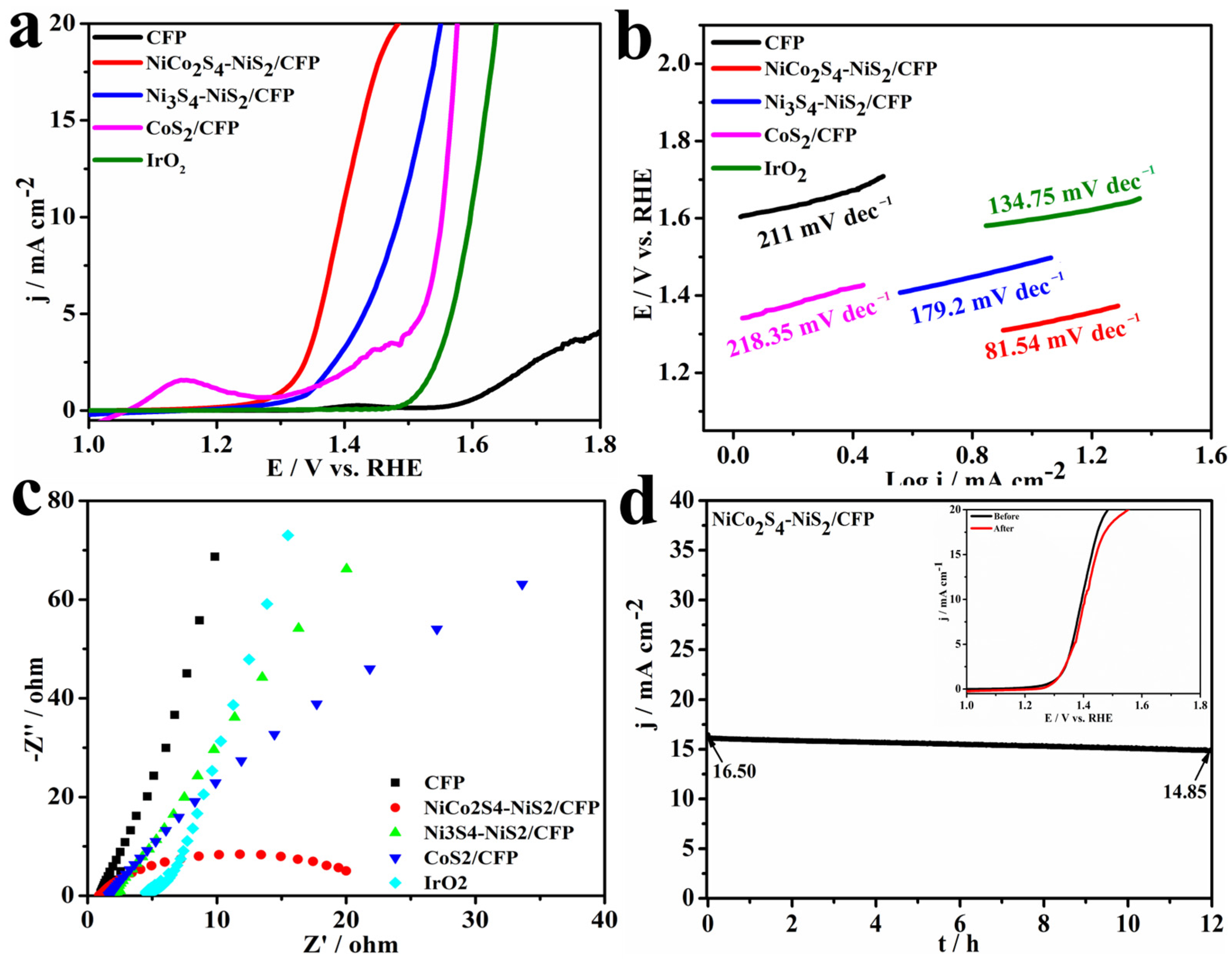
Figure 6.
The XPS spectra of NiCo2S4-NiS2/CFP before and after 12 h durability tests: (a,d) Ni 2p, (b,e) Co 2p and (c,f) S 2p.
Figure 6.
The XPS spectra of NiCo2S4-NiS2/CFP before and after 12 h durability tests: (a,d) Ni 2p, (b,e) Co 2p and (c,f) S 2p.

Figure 7.
Electrochemical double-layer capacitances. (a) Linear fitting of △j at 0.10 V vs. RHE as a function of the scan rate. (b) NiCo2S4-NiS2/CFP. (c) IrO2. (d) Ni3S4-NiS2/CFP. (e) CoS2/CFP.
Figure 7.
Electrochemical double-layer capacitances. (a) Linear fitting of △j at 0.10 V vs. RHE as a function of the scan rate. (b) NiCo2S4-NiS2/CFP. (c) IrO2. (d) Ni3S4-NiS2/CFP. (e) CoS2/CFP.

Table 1.
The synthesis of four kinds of sample.
| Sample | Thiourea (mol) | Co2+ (mmol) | Ni2+ (mmol) | SDS (mmol) | DI Water (mL) |
|---|---|---|---|---|---|
| NiCo2S4-NiS2/CFP | 0.1 | 1.42 | 2.84 | 0.6 | 60 |
| Ni3S4-NiS2/CFP | 0.1 | / | 4.26 | 0.6 | 60 |
| Co2S/CFP | 0.1 | 4.26 | / | 0.6 | 60 |
Disclaimer/Publisher’s Note: The statements, opinions and data contained in all publications are solely those of the individual author(s) and contributor(s) and not of MDPI and/or the editor(s). MDPI and/or the editor(s) disclaim responsibility for any injury to people or property resulting from any ideas, methods, instructions or products referred to in the content. |
© 2023 by the authors. Licensee MDPI, Basel, Switzerland. This article is an open access article distributed under the terms and conditions of the Creative Commons Attribution (CC BY) license (https://creativecommons.org/licenses/by/4.0/).
Share and Cite
MDPI and ACS Style
Li, J.; Xia, Y.; Luo, X.; Mao, T.; Wang, Z.; Hong, Z.; Yue, G. Bi-Phase NiCo2S4-NiS2/CFP Nanocomposites as a Highly Active Catalyst for Oxygen Evolution Reaction. Coatings 2023, 13, 313. https://doi.org/10.3390/coatings13020313
AMA Style
Li J, Xia Y, Luo X, Mao T, Wang Z, Hong Z, Yue G. Bi-Phase NiCo2S4-NiS2/CFP Nanocomposites as a Highly Active Catalyst for Oxygen Evolution Reaction. Coatings. 2023; 13(2):313. https://doi.org/10.3390/coatings13020313
Chicago/Turabian StyleLi, Jintang, Yongji Xia, Xianrui Luo, Tianle Mao, Zhenjia Wang, Zheyu Hong, and Guanghui Yue. 2023. "Bi-Phase NiCo2S4-NiS2/CFP Nanocomposites as a Highly Active Catalyst for Oxygen Evolution Reaction" Coatings 13, no. 2: 313. https://doi.org/10.3390/coatings13020313
Note that from the first issue of 2016, this journal uses article numbers instead of page numbers. See further details here.