Article

Oxidation Behavior of NiCoCrAlY Coatings Deposited by Vacuum Plasma Spraying and High-Velocity Oxygen Fuel Processes

1
Department of Materials Convergence and System Engineering, Changwon National University, Changwon 51140, Republic of Korea
2
School of Materials and Metallurgy Engineering, University of Science and Technology Liaoning, Anshan 114051, China
3
Department of Mechanical and Energy Engineering, Indiana University—Purdue University Indianapolis, Indianapolis, IN 46202-5132, USA
*
Authors to whom correspondence should be addressed.
Coatings 2023, 13(2), 319; https://doi.org/10.3390/coatings13020319
Submission received: 31 December 2022 / Revised: 24 January 2023 / Accepted: 28 January 2023 / Published: 1 February 2023
(This article belongs to the Special Issue Science and Technology of Thermal Barrier Coatings II)

Abstract

:
To reduce the formation of detrimental complex oxides, bond coatings in the thermal barrier coatings for gas turbines are typically fabricated using vacuum plasma spraying (VPS) or the high-velocity oxygen fuel (HVOF) process. Herein, VPS and HVOF processes were applied using NiCoCrAlY + HfSi-based powder to assess the oxidation behavior of the bond coatings for both coating processes. Each coated sample was subjected to 50 cyclic heat treatments at 950 °C for 23 h and cooling for 1 h at 20 °C with nitrogen gas, and the weight change during the heat treatment was measured to evaluate the oxidation behavior. After the oxidation test, the coating layer was analyzed with X-ray diffraction (XRD), scanning electron microscopy (SEM), and energy-dispersive spectroscopy (EDS). The VPS coating exhibited faster weight gain than the HVOF coating because the alumina particles generated during the initial formation of the HVOF coating inhibited oxidation and diffusion. The VPS coating formed a dense and thick thermal growth oxide (TGO) layer until the middle of the oxidation test and remained stable until the end of the evaluation. However, the HVOF coating demonstrated rapid weight loss during the final 20 cycles. Alumina within the bond coat suppressed the diffusion of internal elements and prevented the Al from being supplied to the surface. The isolation of the Al accelerated the growth of spinel TGO due to the oxidation of Ni, Co, and Cr near the surface. The as-coated VPS coating showed higher hardness and lower interfacial bonding strength than the HVOF did. Diffusion induced by heat treatment after the furnace cyclic test (FCT) led to a similar internal hardness and bonding strengths in both coating layers. To improve the quality of the HVOF process, the densification of the coating layer, suppression of internal oxide formation, and formation of a dense and uniform alumina layer on the surface must be additionally implemented.

1. Introduction

Thermal barrier coating systems (TBCs) are applied to high-temperature parts of gas turbines for protecting the base metal (superalloy) from high-temperature and high-pressure environments [1,2,3,4]. TBCs are typically composed of three layers on the substrate. The top layer is a ceramic top coat, which provides a thermal barrier with low thermal conductivity [5]. The bottom layer is a bond coat, which helps mitigate the difference in the coefficient of thermal expansion between the top coat and substrate. Moreover, the bond coat suppresses oxidation and corrosion caused by the air and salts that may penetrate the porous top coat. The middle layer is a thermal growth oxide (TGO) layer, which is grown at the interface between the top coat and the bond coat through the diffusion of metallic elements from the bond coat [6,7,8]. The bond coat is a crucial functional layer that increases the lifespan of a gas turbine by mitigating the difference in the thermal expansion coefficient between the base material and the top coat and by protecting against oxidation and corrosion [9].
The bond coat of a TBC is typically fabricated using one of the following three thermal spray processes: air plasma spraying (APS), VPS, or HVOF. The most suitable process depends on the specific coating application and the desired atmosphere, deposition speed, flame temperature, and coating parameters. VPS can produce a dense and high-quality microstructure with less oxidation [10,11], but it is also the most expensive and time-consuming process because it requires the use of a vacuum or controlled atmosphere. APS is a simpler and less expensive process, but it can result in excessive oxidation during coating, which limits its application to high-temperature parts that require a high-quality bond coat. An HVOF can produce a denser coating than APS due to its lower temperature and faster deposition rate [12,13,14]. An HVOF has been used as an alternative to VPS for bonding coat fabrication due to the presence of finely dispersed Al in the coating layer [15]. The Al is partly oxidized during the HVOF process due to the lower temperature and faster speed than VPS, which can promote oxide nuclei formation and suppress diffusion in the coating layer [15]. The bond coat feedstock can be chosen based on the desired composition and intended use, as the oxidation and corrosion resistance behaviors can vary depending on the composition of the feedstock. To eliminate other factors and concentrate on the oxidation behavior of the several processes utilized, the widely used and well researched NiCoCrAlY + HfSi [16,17,18] was chosen as the feedstock for this study.
The growth of the TGO at the interface between the bond coat and the top coat is significantly influenced by the composition [19], process of the bond coat [20], and oxygen content [21]. The oxide scale can cause delamination between the top coat and the TGO when it reaches a critical thickness (10 μm) [22,23,24]. However, the TGO layer, which is dense and thin at the early stage, can enhance the bonding strength of the top coat/bond interface and hinder further oxidation of the bond coat and substrate due to its low oxygen permeability. For bond coatings made of NiCoCrAlY + HfSi, the oxide scale is typically composed of Al2O3, but other phases and spinel TGO may also be observed depending on the process and oxidation stage [25,26]. There have been numerous studies on the oxidation behavior of bond coats and TGOs. Waltraut et al. [15,27] reported that the NiCoCrAlYRe bond coat produced by an HVOF oxidized more slowly than a VPS bond coat. Ali Raza et al. [28] reported on the porosity and its corrosion effects according to the oxygen flow rate and spray distance of the HVOF coating. Even for the same material, differences may occur depending on process parameters. This suggests that desired characteristics can be expressed to control process parameters.
The oxidation behavior and changes in physical properties of MCrAlY (M = Ni, Co, or both) coatings after annealing have been extensively studied. However, there has been relatively little research on the degradation behavior of bond coats under thermal cyclic testing and the resulting changes in mechanical properties. Therefore, NiCoCrAlY + HfSi powder was formed through the HVOF and VPS processes without annealing, and the durability was compared based on the bond coat formation process through thermal durability evaluation, microstructure analysis, and Vickers hardness testing. In this study, the effect of the bond coating formation process on the durability of the coating system was identified, and the applicability of the relatively inexpensive HVOF process as an alternative to VPS was evaluated.

2. Materials and Method

2.1. Preparation of the Coating Layer

The bond coat was produced with a target thickness of approximately 200 μm on Inconel 792 and Nimonic 263 substrates with a diameter of 25.4 mm × 3 mm using Amdry 386 (NiCoCrAlY + HfSi, Oerlikon Metco, San Diego, CA, USA) powder through the VPS and HVOF processes, respectively. The detailed coating parameters were presented in our previous study [29]. The chemical composition of the materials and feedstock used in this study is shown in Table 1. Since the weight change of the Ni-base superalloys at 950 °C does not decrease and converges to a constant value [30], the weight change of the superalloys was ignored and the substrate was not removed. This was done to eliminate the effect of the weight change of the substrate on the results of the study.

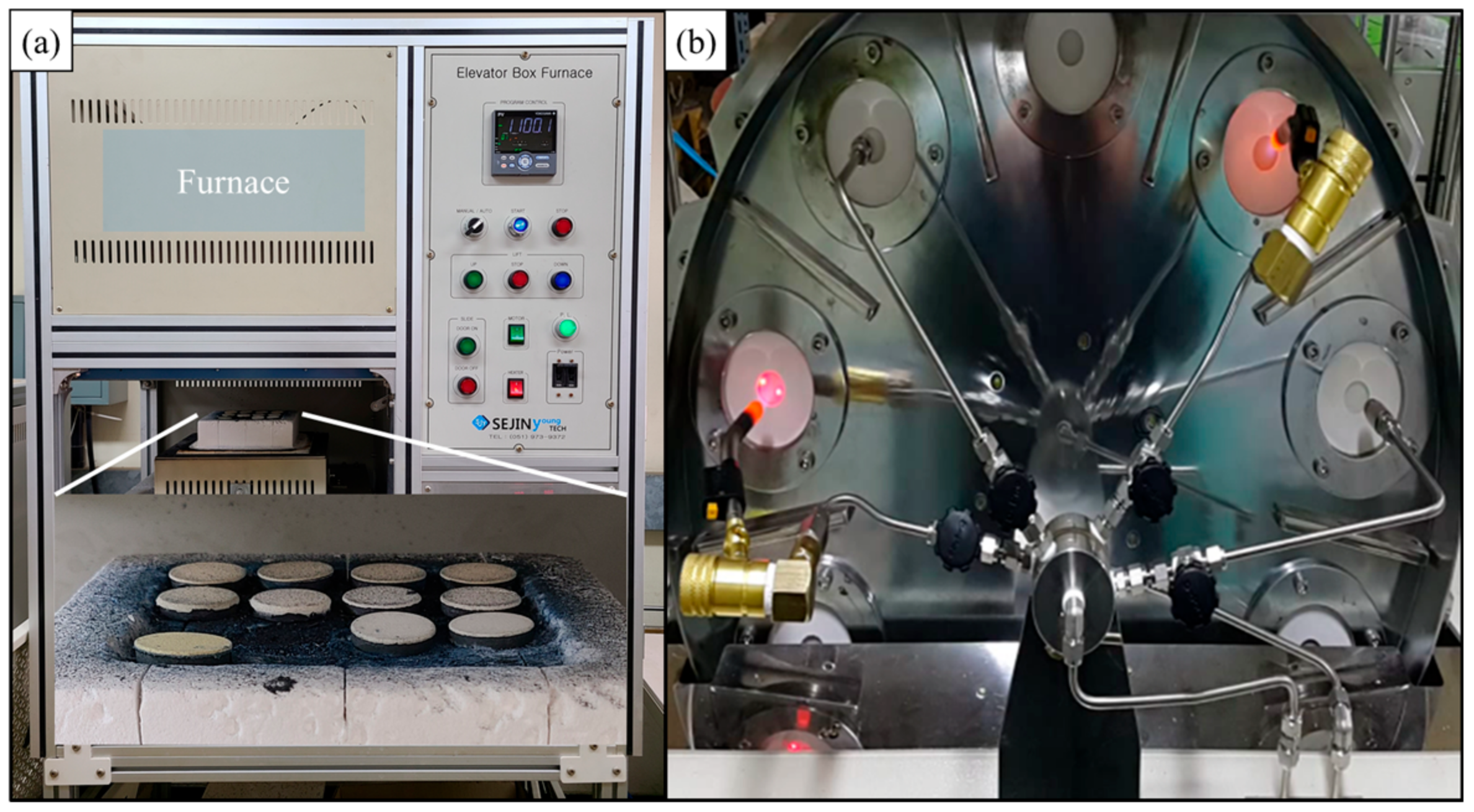
2.2. Thermal Durability Evaluation and Preparation of Analysis Specimens

After coating, the surface roughness (Ra) was measured using a surface roughness measuring instrument (SJ310; Mitutoyo, Japan) at a measuring speed of 0.25 mm/s. The FCT and jet engine thermal shock (JETS) test were conducted to evaluate the thermal durability of the coating layer. In the FCT, the samples were placed in the 950 °C atmosphere furnace and heated for 23 h. Then, the samples were cooled to 20 °C for 1 h, and their weight was measured. The weighed samples were placed in the 950 °C atmosphere furnace again, and this process was repeated 50 times. The weight change of each sample was measured to the fourth decimal place using an analytical balance. The JETS test involved heating the specimen surface with flames to 1400 °C for 20 s and cooling the surface with 20 °C nitrogen for 20 s. This cycle was repeated for up to 2000 cycles. The FCT and JETS equipment are shown in Figure 1.
After the thermal performance tests, all specimens, including the as-coated samples, were cold-mounted using epoxy resin and hardener for a microstructure analysis. The mounted specimens were sequentially polished using emery papers with mesh sizes ranging from 100 to 2000 and diamond paste with sizes 9.0, 3.0, and 1.0 μm. The polished surface was cleaned with ethanol using ultrasonic cleaning and then dried. To evaluate the mechanical properties and bonding strength, Vickers hardness was measured using a hardness testing machine (HV-100; Mitutoyo, kawasaki, Japan) at 10 points on the bond coat cross-section and interface of the coating layer. The average value was calculated after excluding the highest and lowest values.

2.3. Characterization

A phase analysis was performed using XRD (Mini Flex II, Rigaku, Tokyo, Japan) with Cu Kα radiation (λ = 1.5418 Å) before and after oxidation. The scan was conducted with a step size of 0.02° and a scan speed of 2°/min. The cross-sectional microstructures were examined using SEM (JSM-5610; JEOL, Akishima, Japan), and the chemical compositions were identified using EDS (Oxford Instruments, Oxford, UK) attached to the SEM.

3. Results

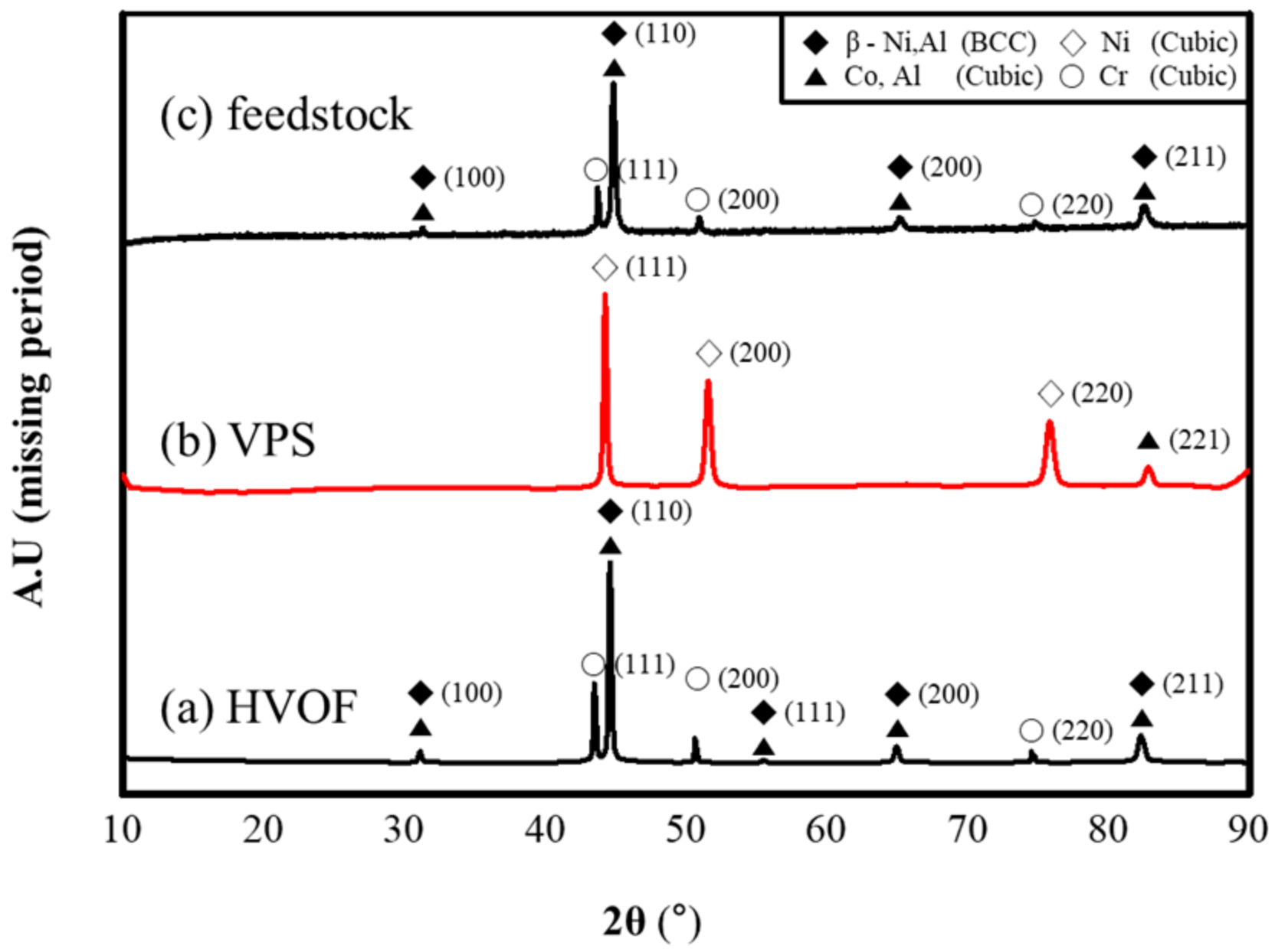
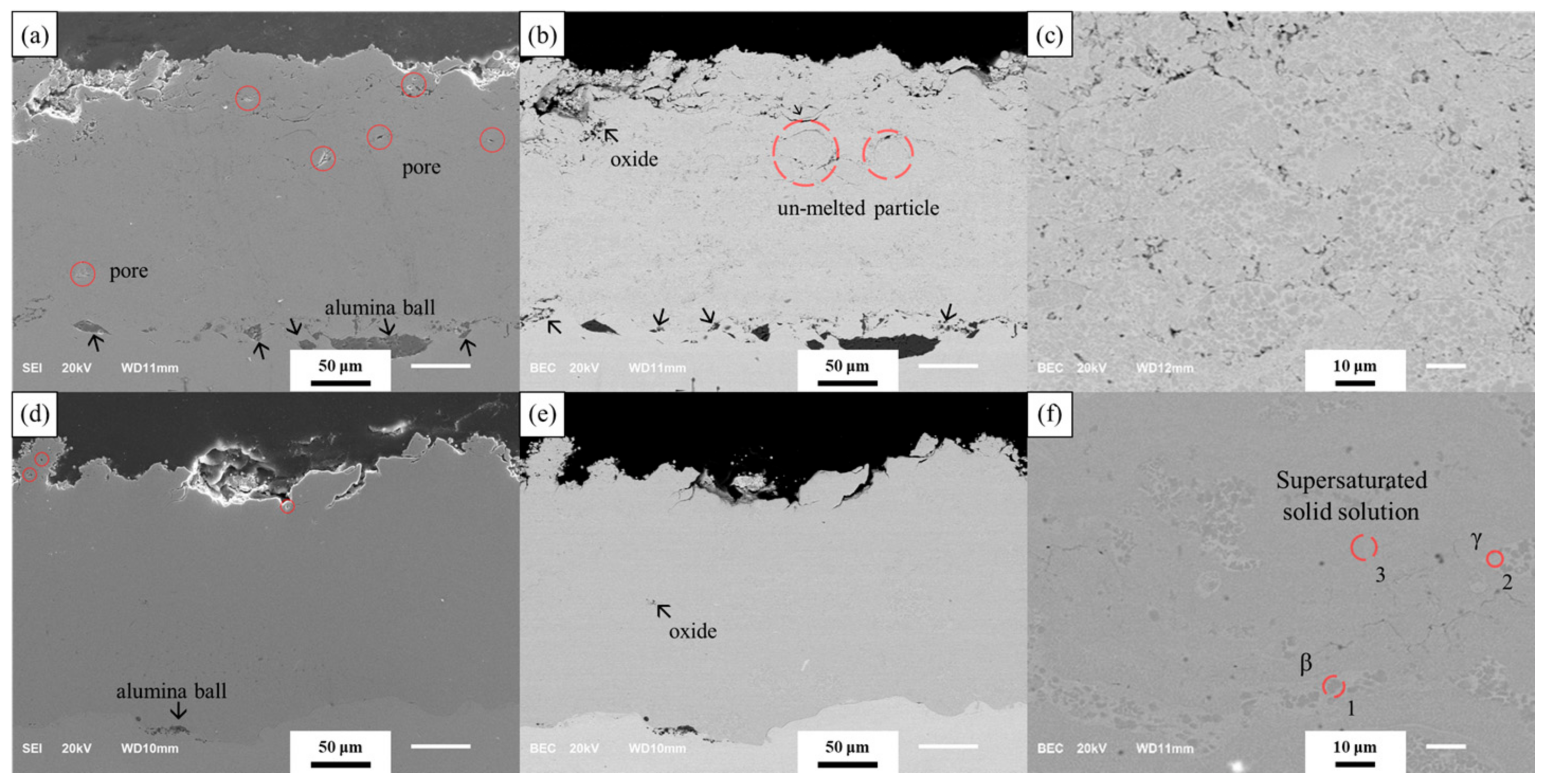
3.1. Analysis of As-Coated Samples

Figure 2 displays the XRD data for both the Amdry 386 feedstock and the coating layer formed by the VPS and HVOF procedures. The XRD analysis revealed that the HVOF coating and the feedstock showed identical peaks, indicating the presence of the basic compositions of Ni, Co, Cr, and Al. Additionally, while alumina was present in the bond coat microstructure, it was not detected by XRD due to its limited amount and location within the coating layer. The VPS bond coat was identified as having a cubic phase with Ni as the primary peak and Co and Al as sub peaks.
Figure 3 shows the microstructures of the bond coats formed by each process. The specimens were not subjected to any specific post-heat treatment after the bond coat was formed in order to focus on the differences between the processes. Although the HVOF bond coat was processed in air, no noticeable oxide layer was observed on the surface. When examining the inside of the bond coat, the porosity + oxidation rate was approximately 2%. The porosity or oxidation rate was analyzed using the ImageJ application based on the difference in contrast and brightness in the SEM image. However, this tool cannot distinguish the contrast and brightness of pores and oxides, so the value measured using imageJ is expressed as the sum of porosity and oxidation rate. However, a visual comparison of the secondary electron imaging (SEI) mode (Figure 3a) and backscattered electron (BSE) mode (Figure 3b) images confirmed that some pores are distributed in the bond coating, and most of the measured values were oxides. In addition to the porosity and oxidation observed within the bond coat, the growth of alumina was observed at the interface between the bond coat and the substrate. The 1000× magnified image in Figure 3c shows that the alumina is relatively uniformly distributed throughout the bond coat. Compared to the HVOF bond coat, the VPS bond coat has cleaner and denser microstructures, and the porosity + oxidation rate of the bond coat was measured to be only 0.05%. The surface roughness of the bond coats formed by each process was also measured. The HVOF bond coat, which has a high process speed, has a relatively low surface roughness of 4.17 ± 1.7 μm while the VPS bond coat has a higher surface roughness of 6.78 ± 0.5 μm.

3.2. Evaluation Result of JETS Test

The samples were heated to 1400 °C for the JETS test using a flame; however, due to the relatively short contact period of 20 s, the temperature reached only 850 °C. After heating for 20 s, the samples were cooled to 20 °C with cooling nitrogen. A JETS test was conducted to analyze the interfacial bonding forces. Figure 4 shows the microstructure of each coating after the JETS test. The JETS test evaluated changes in the coatings due to stress caused by thermal expansion coefficient differences during the rapid heating and cooling cycles. There were minimal changes to the microstructure of the coating as a result of oxidation and deterioration during the short oxidation heating cycle in the test. As a result, the coating retained a shape similar to that of the as-coated samples. In both specimens, the presence of un-melted particles inside the bond coat was observed in the 1000× magnification image (Figure 4c,f). However, there were significant differences in the interface between the specimens. The HVOF bond coat exhibited a sound microstructure while cracks were observed at the interface between the VPS bond coat and the substrate. These cracks were likely caused by the stress resulting from the difference in the thermal expansion coefficient during the JETS test due to the low physical bonding force induced by the low deposition rate of the VPS process. As a result, the HVOF bond coat, with a coating layer deposited at a higher coating speed than VPS, exhibited a sound interface between the bond coat and the substrate even after the JETS test.

3.3. Evaluation Result of FCT

Figure 5 shows the microstructure and EDS analysis results after the FCT of each bond coat. After the FCT, a TGO was observed in both coatings. The FCT involved heating the samples at 950 °C for a total of 1150 h, and it was thought that sintering from diffusion inside the bond coat had progressed. However, it was confirmed that some pores remained in the bond coat. During the porosity + oxidation rate measurement inside the bond coat, the porosity was expected to be partially reduced by sintering. However, the measured value increased to approximately 3% due to the growth of the oxide. An EDS analysis showed that Al2O3 TGO grew on both coating surfaces. In certain areas of the VPS bond coat, spinel TGO was also observed, but it was less prominent than that in the HVOF bond coat. Delamination mainly occurred around the spinel TGO because it is more brittle than Al2O3 TGO [16,34]. Figure 5a shows that the spinel TGO was peeled off in the HVOF bond coat. In contrast, although some cracks were observed in the VPS TGO, which is mainly composed of Al2O3 TGO, delamination did not occur. In both bond coats, the surface roughness increased due to the formation of TGO, with the values for HVOF and VPS measured at 6.78 ± 0.5 and 10.09 ± 0.4 μm, respectively. This represented an increase of approximately 2.5 and 3.31 μm, respectively, compared to the surface roughness value of the as-coated samples.
Figure 6 shows the weight change of the two specimens during the FCT. Generally, VPS bond coats exhibit better durability than HVOF bond coats [10,11], which was confirmed by measuring the weight behavior during the FCT. The weight change behavior was divided into four stages based on the number of cycles: up to 5 cycles were classified as the first stage, up to 15 cycles as the second stage, up to 30 cycles as the third stage, and the remaining cycles as the fourth stage. In the first stage, both coatings exhibited rapid weight gain. In the second stage, a steady increase in weight occurred, but with a decrease in the slope. In the third stage, weight loss was observed in the VPS bond coat while the HVOF bond coat showed no weight change. In the fourth stage, the VPS bond coat maintained a constant weight with little change while the HVOF bond coat showed rapid weight loss.

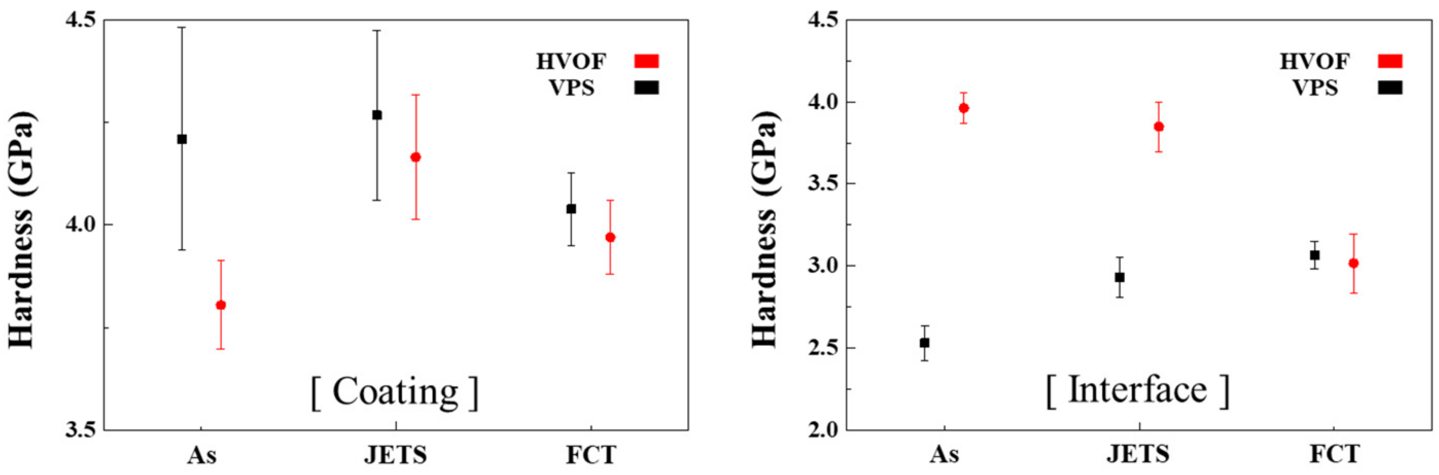
3.4. Vickers Hardness of Each Coating

Figure 7 shows the Vickers hardness measurements at the center of the coating and at the interface before and after the evaluations. The hardness of the VPS bond coat was higher than that of the as-coated HVOF bond coat after the JETS test and FCT. However, the hardness of the as-coated HVOF and the VPS bond coat converged to similar values after the FCT. The hardness of the interface was measured to compare the bonding strength. The HVOF bond coat showed a higher hardness in the as-coated sample and after the JETS tests, but the values converged to similar levels after the FCT.

4. Discussion

4.1. Analysis of As-Coated Samples

Although powders with the same composition were used for the HVOF and VPS coatings, the XRD results differed depending on the temperature and spray speed used during the process. In the case of the HVOF, all basic compositions of Ni, Co, Cr, and Al in the powder could be observed in Figure 2a. However, the VPS bond coat was deposited on the substrate in a sufficiently molten state due to the high temperature and low spray speed. As a result, phase separation did not occur due to quenching, and most of the Ni single phase was in the form of a supersaturated solid solution, in which the β phase was not precipitated.
VPS bond coats typically exhibit a microstructure with low porosity, low oxidation, and a surface roughness that is suitable for top coating compared to HVOF bond coats [35]. The VPS bond coat has significantly fewer un-melted particles, splat boundaries, and oxide inside the coating than the HVOF bond coat does, as observed in the 1000× magnification images. This is because VPS coatings are applied at higher temperatures and lower speeds, which allows most of the powder to be fully melted and stacked. Quenching at a high temperature allows the powder to remain in a single-phase supersaturated solid solution, preventing the β phase from being precipitated. As a result, VPS bond coats exhibit excellent corrosion resistance, hardness, and wear characteristics.
The results of the EDS analysis of the VPS bond coat (Table 2) demonstrated the single-phase region in the form of a supersaturated solid solution, in which the β-phase was not precipitated. When the supersaturated solid solution was compared with the β and γ phases, the Ni content was the same, but the Al, Co, and Cr content converged to a level between the β and γ phases. Because Y, Hf, and Si contribute to increase bonding strength [36,37,38,39], they were barely detected by EDS owing to their relatively low concentrations compared with those of the other elements.

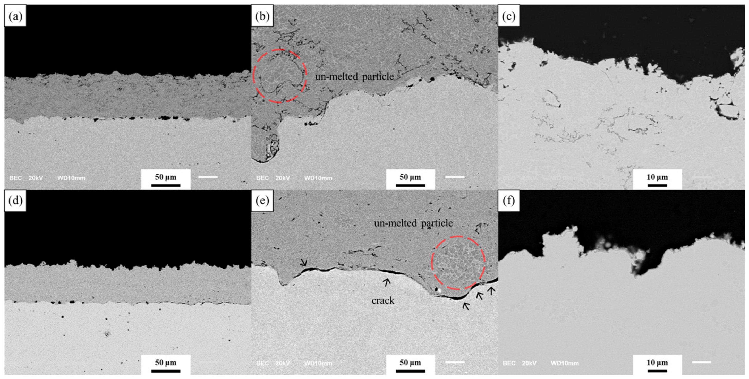
4.2. Microstructure Analysis after FCT

The β phase in both coatings is depleted at the bond coat surface and bond/substrate interface. The VPS bond coat exhibits more extensive depletion of the β phase compared to the HVOF bond coat. The β phase inside the bond coat acts as an Al reservoir, and the most reactive Al diffuses from the bond coat to the surface and reacts with oxygen to form an Al2O3 TGO [13,40]. The primary difference between the coatings after the FCT is the thickness of the TGO and the ratio of Al2O3 TGO and spinel TGO that forms. In the HVOF process, Al2O3 oxide that is formed through powder oxidation during the coating process exists inside the bond coat. During the FCT evaluation, the Al inside the bond coat diffuses to the surface and steadily grows an Al2O3 TGO layer. However, the Al2O3 oxide layer inside the coating layer also reacts with oxygen penetrating through surface cracks, hindering the formation of Al2O3 TGO on the surface by inhibiting the diffusion of Al, Ni, Co, and Cr that react with oxygen to form spinel TGO on surfaces that are not supplied with sufficient Al. Spinel TGO is porous and does not effectively prevent the penetration of oxygen into surface defects.
Additionally, spinel TGO is brittle, and cracks can form during the FCT evaluation, accelerating oxidation. In TGO that has grown above a certain thickness, cracks can propagate around the brittle spinel TGO, and delamination can occur due to the stress caused by the difference in the thermal expansion coefficient between the bond coat and TGO. This is thought to be the main cause of weight reduction in the fourth stage of oxidation. However, the VPS process produced a coating with a lower porosity + oxidation rate than the HVOF process due to the high temperature and vacuum conditions used during the coating process. As a result, the surface of the VPS bond coat was consistently supplied with Al from inside the bond coat and formed a dense, uniform Al2O3 TGO that was approximately twice as thick as the HVOF Al2O3 TGO. This is because the formation of Al2O3 oxide was not observed within the VPS bond coat. We confirmed that the densely and uniformly formed Al2O3 TGO at the 3rd stage of oxidation effectively suppressed further internal oxidation and maintained a constant weight.
The compositions of spectra 1–16 analyzed in Figure 5 are presented in Table 3. Spectra 1–8 and 9–16 were analyzed in the enlarged microstructure of the HVOF and VPS surfaces, respectively, and the γ, β, Al2O3, and spinel TGO areas in the microstructure were analyzed at two points. Upon comparison of the four areas analyzed at two points, they showed almost similar compositions. Spinel TGO exhibited the largest deviation. This is because the formation of spinel TGO involves the mixing of each element rather than the combination of specific elements influenced by the surrounding environment [15,41,42,43]. Both coatings were heat-treated at 950 °C for a total of 1150 h. The single phase present in the as-coated VPS, which was in the form of a supersaturated solid solution and did not contain the β phase due to quenching at high temperature, was separated into β and γ through annealing at 950 °C for 1150 h [44]. This was confirmed through EDS analysis.

4.3. Oxidation Behavior of Each Coating after FCT

During the first stage of oxidation (~5 cycles), a rapid weight increase was observed with almost the same slope in both coating layers, indicating that the oxidation of the base material surface and the bond coat occurred simultaneously. Superalloys typically experience rapid oxidation in the initial stage but maintain a constant value during later stages of oxidation [30]. Therefore, in this experiment, the analysis was conducted excluding the weight change of the parent material. During the second stage of oxidation (~15 cycles), the steady weight increase of both the HVOF and VPS was likely due to the growth of the oxide layer on the surface of the coatings. The weight increase of the HVOF bond coat was relatively reduced compared to the VPS bond coat due to the presence of Al2O3 that forms during the coating process and hinders diffusion. In contrast, the VPS bond coat experienced a faster weight increase compared to the HVOF bond coat due to relatively unrestricted oxidation, as there is less Al2O3 present in the bond to inhibit diffusion. During the third stage of oxidation (~30 cycles), a slight weight decrease was observed for the VPS bond coat while the weight of the HVOF bond coat remained constant. During the FCT process, Al2O3 grew on the surface as the HVOF bond coat underwent oxidation. However, the supply of Al for forming Al2O3 was not stable from the bond coat due to the presence of internal oxides.
As a result, the growth of spinel TGO was more prominent on the HVOF bond coat than on the VPS bond coat due to the diffusion of Ni, Co, and Cr near the surface. While the weight remained constant, the thinner Al2O3 TGO on the HVOF bond coat was unable to effectively control the diffusion of elements within the coat, leading to the repeated formation and removal of spinel oxide. As shown in Figure 5d, cracks were formed in the coating’s microstructure. In contrast, the VPS TGO was able to stably supply Al from the bond coat, which was located deeper in the coat and formed a bond coat approximately twice as dense as the HVOF bond coat due to the lower amount of internal oxide than in the VPS bond coat. As a result, the depletion zone of the VPS bond coat was deeper than that of the HVOF bond coat. However, the VPS TGO did not completely control the formation of spinel TGO, and the weight decreased slightly due to the delamination of brittle spinel TGO in certain areas, as shown in Figure 5f. During the fourth and final stage of oxidation, the HVOF and VPS bond coats exhibited considerably different oxidation behaviors, with rapid weight loss observed in the HVOF bond coat. The stress caused by the thermal shock during FCT heating and cooling was transmitted from the brittle spinel TGO interface along the Al2O3 TGO/base metal interface, causing the growth and delamination of cracks, as shown in Figure 5c. On the contrary, the VPS bond coat experienced minimal weight change due to the dense formation of Al2O3 TGO, which effectively inhibited oxidation. However, magnification of the microstructure revealed the presence of cracks in the Al2O3 TGO of the VPS bond coat, as shown in Figure 5f. The cracks are influenced by the thermal stress generated during FCT heating and cooling. If the evaluation process continues over a long period of time, the TGO will increase in thickness due to continuous oxidation within the formed cracks. Once the TGO grows to a sufficient thickness, the difference in the thermal expansion coefficient between the TGO and bond coat is expected to cause stress that will cause delamination [45]. In the future, FCT evaluation will be conducted starting at the point of conversion for each oxidation step to analyze the thickness of the TGO, the growth rate of the spinel TGO and Al2O3 TGO, and the time of crack occurrence for each oxidation step. Long-term FCT evaluation will also be conducted to further assess the durability and performance of the TGO layers over time.

4.4. Analysis of Vickers Hardness

The VPS coating exhibited a higher hardness than the HVOF coating both before and after the thermal durability evaluation. This is likely due to the higher density of the VPS coating, which has a high hardness of supersaturated solid solution [46] and fewer defects, including those that are internal, compared to the HVOF coating. After the JETS test, a slight increase in hardness was observed for both coatings, suggesting that the heat during the JETS test may have partially sintered and removed internal defects in the coatings. However, it was difficult to confirm any differences in the microstructure. After FCT, a slight decrease in hardness was observed for both coatings. The internal residual stress generated during the powder melting and depositing process of the coating was relieved and annealed from their exposure to a heat source for a sufficient amount of time. This resulted in a decrease in the internal stress of the coating and a corresponding decrease in hardness. In particular, in the case of VPS, a supersaturated solid solution with excellent hardness is phase-separated into β and γ during annealing.
Because of the thin bond coating, the ASTM C-633 technique could not be adopted to evaluate the adhesive strength between the bond coating and the substrate in this study. Therefore, the Vickers hardness of each coating interface was used as a relative comparison. The VPS coating had a higher hardness at the center of the bond coat cross-section while the HVOF coating had a higher hardness at the interface, as demonstrated upon analyzing the as-coated samples. This suggests that the HVOF coating, rather than the VPS coating, exhibited greater bonding strength with the substrate. Compared to VPS, the HVOF is deposited at a faster rate, which results in a higher bonding strength due to physically strong interlocking. After the FCT evaluation, the bonding strength of both coatings converged to a value of 3.0. This is because annealing relieved the residual stress within the material. The bonding strength of the VPS coating increased through the diffusion of the bond coat and substrate from their exposure to adequate heat for a sufficient amount of time. This suggests that the bonding strength of both coatings can be similarly controlled through heat treatment.

4.5. Applicability and Development Direction of HVOF

Gas turbines are composed of several stages of high-temperature components such as vanes and blades. Gas turbines are subject to various failure mechanisms that act in combination, which can be classified as thermal, thermomechanical, and chemical destruction mechanisms [47,48]. Since the front part of the high-temperature components is exposed to a relatively high heat source, a top coat with excellent insulation must be applied. However, the back part of high-temperature components is exposed to relatively low heat sources, so protection like oxidation and wear resistance is more important than heat resistance. Moreover, since there is no top coat, the back part is largely free from the stress generated during oxide growth and the brittle characteristics of spinel TGO. Therefore, an HVOF bond coat, which has superior initial bonding strength and hardness as compared to VPS, is a good substitute for high-temperature parts at the lower stage; moreover, this process is economical and highly productive.
The HVOF, however, carries a risk of failure because it requires the application of spinel TGO to the front area where excellent quality is required. Therefore, it is necessary to improve the quality of the HVOF and VPS, which are preferred in practical applications due to their simplicity and cost-effectiveness. To improve the quality of HVOF coatings, three methods have been proposed. The first is to densify the coating layer through process-variable control. By optimizing the process for each powder, the quality of the coating can be improved by sufficiently melting the powder to eliminate internal pores in the coating layer. The second method is to use a shielding gas during the process, which can inhibit the diffusion of the Al2O3 oxide within the bond coat. This can suppress the formation of internal Al2O3, which is necessary for the growth of spinel TGO. Spinel TGO grows when the diffusion of internal Al is difficult for it to migrate to the surface. The third method involves the growth of Al2O3 TGO of sufficient thickness through post-heat treatment in a vacuum. Under standard oxygen partial pressure conditions, Al2O3 and spinel TGO grow together. However, in a low-oxygen partial-pressure environment, thermally stable Al2O3 is preferentially formed [20,49,50,51]. The growth of dense and uniform Al2O3 TGO with a sufficient thickness effectively prevents the penetration of oxygen and protects the bond coat from oxidation [52,53].

5. Conclusions

In this study, bond coats were formed using both the HVOF and VPS processes with NiCoCrAlY + HfSi powder. The degradation behavior and mechanical properties of the resulting bond coats were analyzed through thermal durability evaluation. Microstructure analysis after the thermal durability evaluation revealed that the HVOF bond coat had a higher mechanical bonding strength with the substrate and better oxidation resistance than the VPS bond coat in the initial oxidation stage without post-heat treatment. However, the HVOF bond coat exhibited rapid weight loss in the later stages of oxidation due to the delamination of the spinel TGO formed by the inhibition of alumina diffusion within the bond coat. As-coated HVOF showed low hardness due to its lower porosity compared to the as-coated VPS specimen but showed excellent adhesion due to the high deposition rate. After the FCT, the porosity inside the HVOF coating was reduced through diffusion, and the supersaturated solid inside the VPS was separated to β and γ phases through sufficient heat treatment. Thus, the HVOF and VPS coatings showed similar hardness after FCT. The interface between the sample and the coating was sufficiently heat-treated so that the residual stress in the HVOF coating was eliminated, and the bonding strength decreased. The VPS coating had a similar bonding strength because the low bonding strength complemented the insufficient physical bonding through diffusion. Surface oxidation control is required to alternate the VPS process with the HVOF process, which has a higher bonding strength of the as-coated sample than VPS.
Therefore, we proposed three methods to improve the quality of the HVOF bond coat to be comparable to that of the VPS bond coat. The first method is to densify the coating layer through process optimization. The second method is to use shielding gas to inhibit the formation of internal alumina. Finally, the third method is to form a dense and uniform Al2O3 TGO through post-heat treatment. Implementing these three methods is expected to improve the quality of the HVOF bond coat to be similar to that of the VPS bond coat.

Author Contributions

Conceptualization, J.K., J.P. and B.-i.Y.; methodology, J.K., B.-G.K. and Y.-g.J.; software, J.K., T.K. and S.Y.; investigation, J.K. and H.C.; writing—original draft preparation, J.K.; writing—review and editing, L.Z., J.Z., B.-i.Y., Y.-g.J. and S.Y.; visualization, J.K. and T.D.; supervision, B.-i.Y. All authors have read and agreed to the published version of the manuscript.

Funding

This work was supported by Korea Institute of Energy Technology Evaluation and Planning (KETEP) grant funded by the Korea government (MOTIE) (20214000000480, Development of R&D engineers for combined cycle power plant technologies), and the Korea Institute for Advancement of Technology (KIAT) grant funded by the Korea Government (MOTIE) (P0017012, Human Resource Development Program for Industrial Innovation). It was financially supported by the National Research Foundation of Korea (NRF) grant funded by the Korea government (MSIT) (2021R1A4A1052059).

Institutional Review Board Statement

Not applicable.

Informed Consent Statement

Not applicable.

Data Availability Statement

Data sharing is not applicable to this article.

Conflicts of Interest

The authors declare no conflict of interest.

References

  1. Padture, N.P.; Gell, M.; Jordan, E.H. Thermal Barrier Coatings for Gas-Turbine Engine Applications. Science 2002, 296, 280–284. [Google Scholar] [CrossRef]
  2. Beele, W.; Marijnissen, G.; Van Lieshout, A. The Evolution of Thermal Barrier Coatings—Status and Upcoming Solutions for Today’s Key Issues. Surf. Coat. Technol. 1999, 120–121, 61–67. [Google Scholar] [CrossRef]
  3. Padture, N.P.; Gell, M.; Klemens, P.G. Ceramic Materials for Thermal Barrier Coatings 2000. J. Eur. Ceram. Soc. 2004, 24, 1–10. [Google Scholar]
  4. Padture, N.P. Advanced Structural Ceramics in Aerospace Propulsion. Nat. Mater. 2016, 15, 804–809. [Google Scholar] [CrossRef]
  5. Smialek, J.L.; Miller, R.A. Revisiting the Birth of 7YSZ Thermal Barrier Coatings: Stephan Stecura. Coatings 2018, 8, 255. [Google Scholar] [CrossRef]
  6. Haynes, J.A. Elevated Temperature Coatings. Sci. Technol. 1999, 185–196. [Google Scholar]
  7. Worch, H.P. Kofstad, High Temperature Corrosion; Elsevier Applied Science: London, UK, 1988; ISBN 1-85166-154-91989. [Google Scholar]
  8. Stiger, M.J.; Yanar, N.M.; Topping, M.G.; Pettit, F.S.; Meier, G.H. Thermal Barrier Coatings for the 21st Century. Z. Fur Met. 1999, 90, 1069–1078. [Google Scholar]
  9. Kawakita, J.; Kuroda, S.; Fukushima, T.; Kodama, T. Development of Dense Corrosion Resistant Coatings by an Improved HVOF Spraying Process. Sci. Technol. Adv. Mater. 2003, 4, 281–289. [Google Scholar] [CrossRef]
  10. Gudmundsson, B.; Jacobson, B.E.; Gruner, H. The Influence of Substrate Temperature on the Microstructure and Hardness of Vacuum-Plasma-Sprayed Co Ni Cr Al Si Zr Y and Co Ni Cr Al Y Alloys. Mater. Sci. Eng. A 1989, 108, 105–115. [Google Scholar] [CrossRef]
  11. Noguchi, K.; Nishida, M.; Chiba, A. Transmission Electron Microscopy of Low Pressure Plasma Sprayed CoNiCrAlY Coating. Scr. Mater. 1996, 35, 1359–1364. [Google Scholar] [CrossRef]
  12. Lugscheider, E.; Herbst, C.; Zhao, L. Parameter Studies on High-Velocity Oxy-Fuel Spraying of MCrAlY Coatings. Surf. Coat. Technol. 1998, 108, 16–23. [Google Scholar] [CrossRef]
  13. Toma, D.; Brandl, W.; Köster, U. Studies on the Transient Stage of Oxidation of VPS and HVOF Sprayed MCrAlY Coatings. Surf. Coat. Technol. 1999, 120, 8–15. [Google Scholar] [CrossRef]
  14. Ajdelsztajn, L.; Picas, J.A.; Kim, G.E.; Bastian, F.L.; Schoenung, J.; Provenzano, V. Oxidation Behavior of HVOF Sprayed Nanocrystalline NiCrAlY Powder. Mater. Sci. Eng. A 2002, 338, 33–43. [Google Scholar] [CrossRef]
  15. Brandl, W.; Toma, D.; Krüger, J.; Grabke, H.J.; Matthäus, G. The Oxidation Behaviour of HVOF Thermal-Sprayed MCrAlY Coatings. Surf. Coat. Technol. 1997, 94, 21–26. [Google Scholar] [CrossRef]
  16. DeMasi-Marcin, J.T.; Gupta, D.K. Protective Coatings in the Gas Turbine Engine. Surf. Coat. Technol. 1994, 68–69, 1–9. [Google Scholar] [CrossRef]
  17. Myoung, S.-W.; Kim, J.-H.; Lee, W.-R.; Jung, Y.-G.; Lee, K.-S.; Paik, U. Microstructure Design and Mechanical Properties of Thermal Barrier Coatings with Layered Top and Bond Coats. Surf. Coat. Technol. 2010, 205, 1229–1235. [Google Scholar] [CrossRef]
  18. Haynes, J.A.; Unocic, K.A.; Pint, B.A. Effect of Water Vapor on the 1100 C Oxidation Behavior of Plasma-Sprayed TBCs with HVOF NiCoCrAlX Bond Coatings. Surf. Coat. Technol. 2013, 215, 39–45. [Google Scholar] [CrossRef]
  19. Brindley, W.J.; Miller, R.A. Thermal Barrier Coating Life and Isothermal Oxidation of Low-Pressure Plasma-Sprayed Bond Coat Alloys. Surf. Coat. Technol. 1990, 43, 446–457. [Google Scholar] [CrossRef]
  20. Saeidi, S.; Voisey, K.T.; McCartney, D.G. The Effect of Heat Treatment on the Oxidation Behavior of HVOF and VPS CoNiCrAlY Coatings. J. Therm. Spray Technol. 2009, 18, 209–216. [Google Scholar] [CrossRef]
  21. Li, C.-J.; Li, W.-Y. Effect of Sprayed Powder Particle Size on the Oxidation Behavior of MCrAlY Materials during High Velocity Oxygen-Fuel Deposition. Surf. Coatings Technol. 2003, 162, 31–41. [Google Scholar] [CrossRef]
  22. Lipkin, D.M.; Clarke, D.R. Measurement of the Stress in Oxide Scales Formed by Oxidation of Alumina-Forming Alloys. Oxid. Met. 1996, 45, 267–280. [Google Scholar] [CrossRef]
  23. Schlichting, K.W.; Padture, N.P.; Jordan, E.H.; Gell, M. Failure Modes in Plasma-Sprayed Thermal Barrier Coatings. Mater. Sci. Eng. A 2003, 342, 120–130. [Google Scholar] [CrossRef]
  24. Wagner, C. Reaktionstypen Bei Der Oxydation von Legierungen. Z. Für Elektrochem. Ber. Der Bunsenges. Für Phys. Chem. 1959, 63, 772–782. [Google Scholar] [CrossRef]
  25. Tang, F.; Ajdelsztajn, L.; Schoenung, J.M. Characterization of Oxide Scales Formed on HVOF NiCrAlY Coatings with Various Oxygen Contents Introduced during Thermal Spraying. Scr. Mater. 2004, 51, 25–29. [Google Scholar] [CrossRef]
  26. Lee, C.H.; Kim, H.K.; Choi, H.S.; Ahn, H.S. Phase Transformation and Bond Coat Oxidation Behavior of Plasma-Sprayed Zirconia Thermal Barrier Coating. Surf. Coat. Technol. 2000, 124, 1–12. [Google Scholar] [CrossRef]
  27. Brandl, W.; Toma, D.; Grabke, H.J. The Characteristics of Alumina Scales Formed on HVOF-Sprayed MCrAlY Coatings. Surf. Coat. Technol. 1998, 108, 10–15. [Google Scholar] [CrossRef]
  28. Raza, A.; Ahmad, F.; Badri, T.M.; Raza, M.R.; Malik, K. An Influence of Oxygen Flow Rate and Spray Distance on the Porosity of HVOF Coating and Its Effects on Corrosion—A Review. Materials 2022, 15, 6329. [Google Scholar] [CrossRef]
  29. Lyu, G.; Song, D.; Kim, J.; Lu, Z.; Yang, B.; Yang, S.; Byeun, Y.; Jung, Y.-G. Multidisciplinary Approach for Investigating the Hot Corrosion Behavior of Thermal Barrier Coatings. J. Eur. Ceram. Soc. 2021, 41, 324–333. [Google Scholar] [CrossRef]
  30. Li, M.H.; Sun, X.F.; Li, J.G.; Zhang, Z.Y.; Jin, T.; Guan, H.R.; Hu, Z.Q. Oxidation Behavior of a Single-Crystal Ni-Base Superalloy in Air. I: At 800 and 900 C. Oxid. Met. 2003, 59, 591–605. [Google Scholar] [CrossRef]
  31. Giese, S.; Neumeier, S.; Bergholz, J.; Naumenko, D.; Quadakkers, W.J.; Vaßen, R.; Göken, M. Influence of Different Annealing Atmospheres on the Mechanical Properties of Freestanding MCrAlY Bond Coats Investigated by Micro-Tensile Creep Tests. Metals 2019, 9, 692. [Google Scholar] [CrossRef]
  32. Kanesund, J.; Moverare, J.; Johansson, S. The Deformation and Damage Mechanisms during Thermomechanical Fatigue (TMF) in IN792. Procedia Eng. 2011, 10, 189–194. [Google Scholar] [CrossRef]
  33. Murthy, G.V.S.; Sridhar, G.; Kumar, A.; Jayakumar, T. Characterization of Intermetallic Precipitates in a Nimonic Alloy by Ultrasonic Velocity Measurements. Mater. Charact. 2009, 60, 234–239. [Google Scholar] [CrossRef]
  34. Miller, R.A. Oxidation-based Model for Thermal Barrier Coating Life. J. Am. Ceram. Soc. 1984, 67, 517–521. [Google Scholar] [CrossRef]
  35. Michels, D.; Hadeler, J.; Lienhard, V.J.H. High-Heat-Flux Resistance Heaters from VPS and HVOF Thermal Spraying. Exp. HEAT Transf. Int. J. 1998, 11, 341–359. [Google Scholar] [CrossRef]
  36. Huntz, A.M. Influence of Active Elements on the Oxidation Mechanism of M Cr Al Alloys. Mater. Sci. Eng. 1987, 87, 251–260. [Google Scholar] [CrossRef]
  37. Stott, F.H.; Wood, G.C. Growth and Adhesion of Oxide Scales on Al2O3-Forming Alloys and Coatings. Mater. Sci. Eng. 1987, 87, 267–274. [Google Scholar] [CrossRef]
  38. Smeggil, J.G. Some Comments on the Role of Yttrium in Protective Oxide Scale Adherence. Mater. Sci. Eng. 1987, 87, 261–265. [Google Scholar] [CrossRef]
  39. Volenik, K.; Novak, V.; Dubský, J.; Chraska, P.; Neufuss, K. Properties of Alloy Steel Coatings Oxidized during Plasma Spraying. Mater. Sci. Eng. A 1997, 234, 493–496. [Google Scholar] [CrossRef]
  40. Wei, T.; Fan, Z.; Luo, G.; Zheng, C.; Xie, D. A Rapid and Efficient Method to Prepare Exfoliated Graphite by Microwave Irradiation. Carbon N. Y. 2009, 47, 337–339. [Google Scholar] [CrossRef]
  41. Mumm, D.R.; Evans, A.G. On the Role of Imperfections in the Failure of a Thermal Barrier Coating Made by Electron Beam Deposition. Acta Mater. 2000, 48, 1815–1827. [Google Scholar] [CrossRef]
  42. Hou, P.Y.; Stringer, J. Room Temperature Strains in Cr2O3 Scales Formed at Elevated Temperatures on Ni-25 wt% Cr and Y-and Al-Doped Ni-25 wt% Cr. Acta Metall. Mater. 1991, 39, 841–849. [Google Scholar] [CrossRef]
  43. Perez, P. Influence of the Alloy Grain Size on the Oxidation Behaviour of PM2000 Alloy. Corros. Sci. 2002, 44, 1793–1808. [Google Scholar] [CrossRef]
  44. Brandl, W.; Grabke, H.J.; Toma, D.; Krüger, J. The Oxidation Behaviour of Sprayed MCrAlY Coatings. Surf. Coat. Technol. 1996, 86, 41–47. [Google Scholar] [CrossRef]
  45. Clarke, D.R.; Pompe, W. Critical Radius for Interface Separation of a Compressively Stressed Film from a Rough Surface. Acta Mater. 1999, 47, 1749–1756. [Google Scholar] [CrossRef]
  46. Sampath, S. Microstructural Characteristics of Plasma Spray Consolidated Amorphous Powders. Mater. Sci. Eng. A 1993, 167, 1–10. [Google Scholar] [CrossRef]
  47. Levi, C.G.; Hutchinson, J.W.; Vidal-Sétif, M.-H.; Johnson, C.A. Environmental Degradation of Thermal-Barrier Coatings by Molten Deposits. MRS Bull. 2012, 37, 932–941. [Google Scholar] [CrossRef]
  48. Raza, A.; Ahmad, F.; Badri, T.M.; Raza, M.R.; Malik, K.; Ali, S. Selection of Materials Based on Thermo-Mechanical Properties of Thermal Barrier Coatings and Their Failures—A Review. Adv. Mater. Sci. Eng. 2023, 255–264. [Google Scholar]
  49. Messaoudi, K.; Huntz, A.M.; Lesage, B. Diffusion and Growth Mechanism of Al2O3 Scales on Ferritic Fe-Cr-Al Alloys. Mater. Sci. Eng. A 1998, 247, 248–262. [Google Scholar] [CrossRef]
  50. Evans, A.G.; Mumm, D.R.; Hutchinson, J.W.; Meier, G.H.; Pettit, F.S. Mechanisms Controlling the Durability of Thermal Barrier Coatings. Prog. Mater. Sci. 2001, 46, 505–553. [Google Scholar] [CrossRef]
  51. Brandes, E.A.; Brook, G.B. Smithells Metals Reference Book; Elsevier: Amsterdam, The Netherlands, 2013; ISBN 0080517307. [Google Scholar]
  52. Ambrico, J.M.; Begley, M.R.; Jordan, E.H. Stress and Shape Evolution of Irregularities in Oxide Films on Elastic–Plastic Substrates Due to Thermal Cycling and Film Growth. Acta Mater. 2001, 49, 1577–1588. [Google Scholar] [CrossRef]
  53. Karlsson, A.M.; Evans, A.G. A Numerical Model for the Cyclic Instability of Thermally Grown Oxides in Thermal Barrier Systems. Acta Mater. 2001, 49, 1793–1804. [Google Scholar]
Figure 1. Equipment used in this study: (a) FCT equipment; (b) JETS test equipment.
Coatings 13 00319 g001
Figure 2. XRD results of as-coated (a) HVOF (b) VPS and (c) feedstock.
Coatings 13 00319 g002
Figure 3. Microstructure analysis of as-coated HVOF (ac) and VPS (df).
Coatings 13 00319 g003
Figure 4. Microstructural analysis after JETS test for HVOF (ac) and VPS (df) coated specimens.
Coatings 13 00319 g004
Figure 5. Microstructure and EDS analysis after FCT for HVOF (ac) and VPS (df) coated.
Coatings 13 00319 g005
Figure 6. Weight change (wt. %) after FCT for HVOF and VPS coated specimens; 1st: 0~5 cycles, 2nd: 5~15 cycles, 3rd: 15~30 cycles, 4th: 30~50 cycles.
Coatings 13 00319 g006
Figure 7. Vickers hardness change after FCT and JETS test for HVOF and VPS coated specimens.
Coatings 13 00319 g007
Table 1. Composition of feedstock powder and substrates.
Composition
(wt. %)
NiCoCrAlYHfSiTaWMoTiFeC
Amdry
386 [31]
Bal.19.016.523.00.360.080.79------
Inconel
792 [32]
Bal.8.912.43.5---4.14.01.84.95-0.8
Nimonic
263 [33]
Bal.19.620.10.4--0.4--6.02.00.70.06
Table 2. Results of EDS analysis of the VPS bond coat shown in Figure 3f.
SpectraPhaseOAlNiCoCrYHfSiTotal
(at. %)
1β (BCC)2.5329.5439.2215.8012.09--0.82100
2γ (FCC)3.1615.3538.0020.7521.48--1.25
3supersaturated solid solution3.7523.1438.9117.7315.41-0.110.95
Table 3. Results of EDS analysis of the VPS bond coat shown in Figure 5.
SpectraPhaseOAlNiCoCrYHfSiTotal
(at. %)
1γ
(FCC)
-9.7839.4326.8922.640.250.040.98100
20.369.9938.8027.0222.410.470.010.94
90.197.9838.7725.0726.850.26-0.88
100.219.0139.9624.5225.310.17-0.81
3β
(BCC)
-34.1449.0211.205.200.05-0.38
40.2334.2948.6811.014.990.200.100.52
11-34.2050.029.605.720.03-0.43
120.7533.7250.249.515.250.10-0.44
5Al2O360.5237.320.730.510.560.340.02-
658.7138.191.170770.820.320.01-
1360.8738.230.220.090.110.320.15-
1460.9837.280.320.170.180.800.27-
7Spinel TGO62.1126.436.323.771.360.01--
864.4616.274.443.5010.600.110.010.6
1564.6517.884.634.707.380.230.070.45
1660.7918.511.251.3416.330.770.020.98
Disclaimer/Publisher’s Note: The statements, opinions and data contained in all publications are solely those of the individual author(s) and contributor(s) and not of MDPI and/or the editor(s). MDPI and/or the editor(s) disclaim responsibility for any injury to people or property resulting from any ideas, methods, instructions or products referred to in the content.

